
Performance and Feasibility Study of a Novel Automated Catch-Hauling Device Using a Flexible Hose Net Structure in Set-Net


Abstract
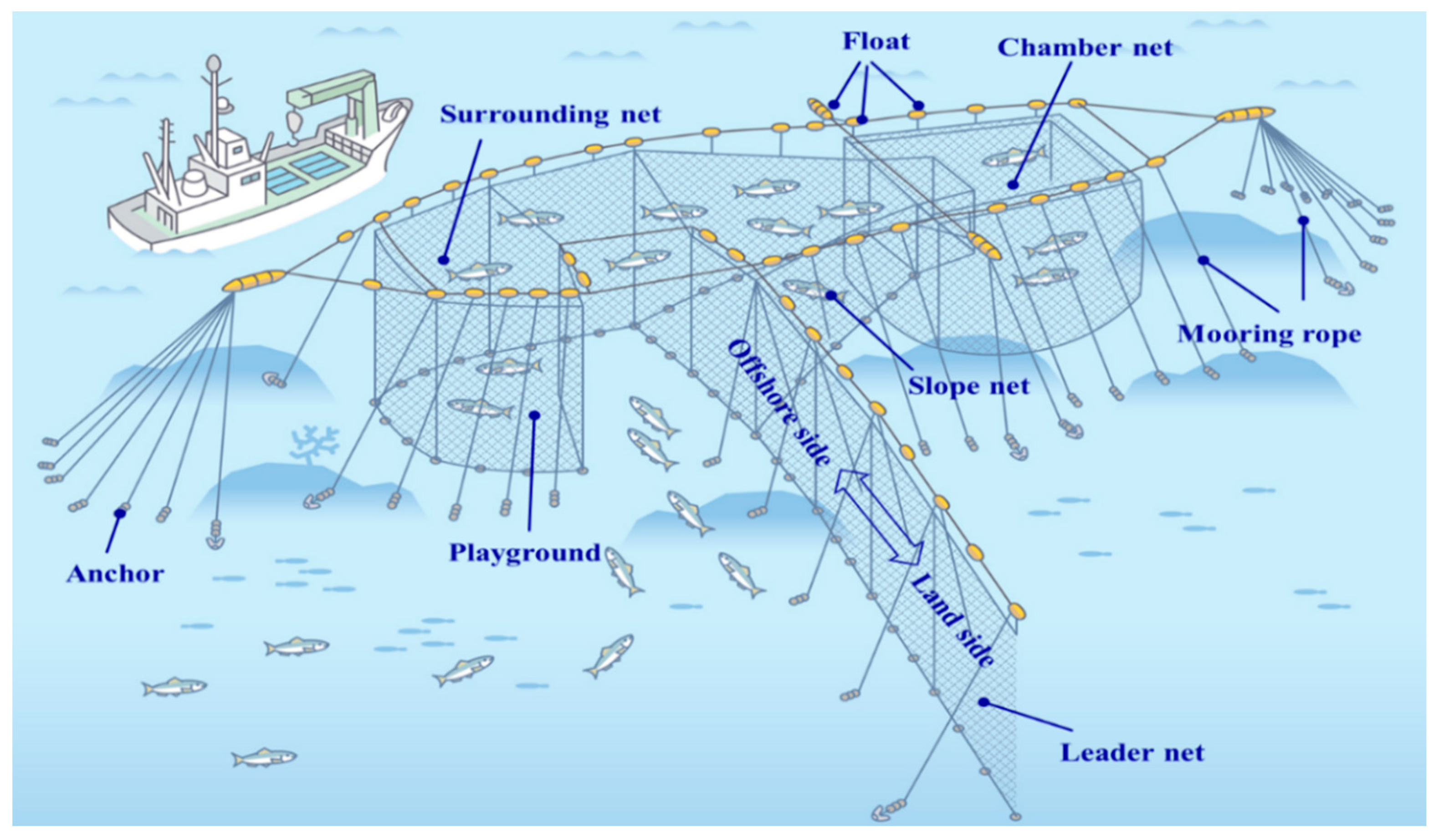
:1. Introduction
2. Material and Methods
2.1. Floating Up and Sinking Experiments of Hose Net
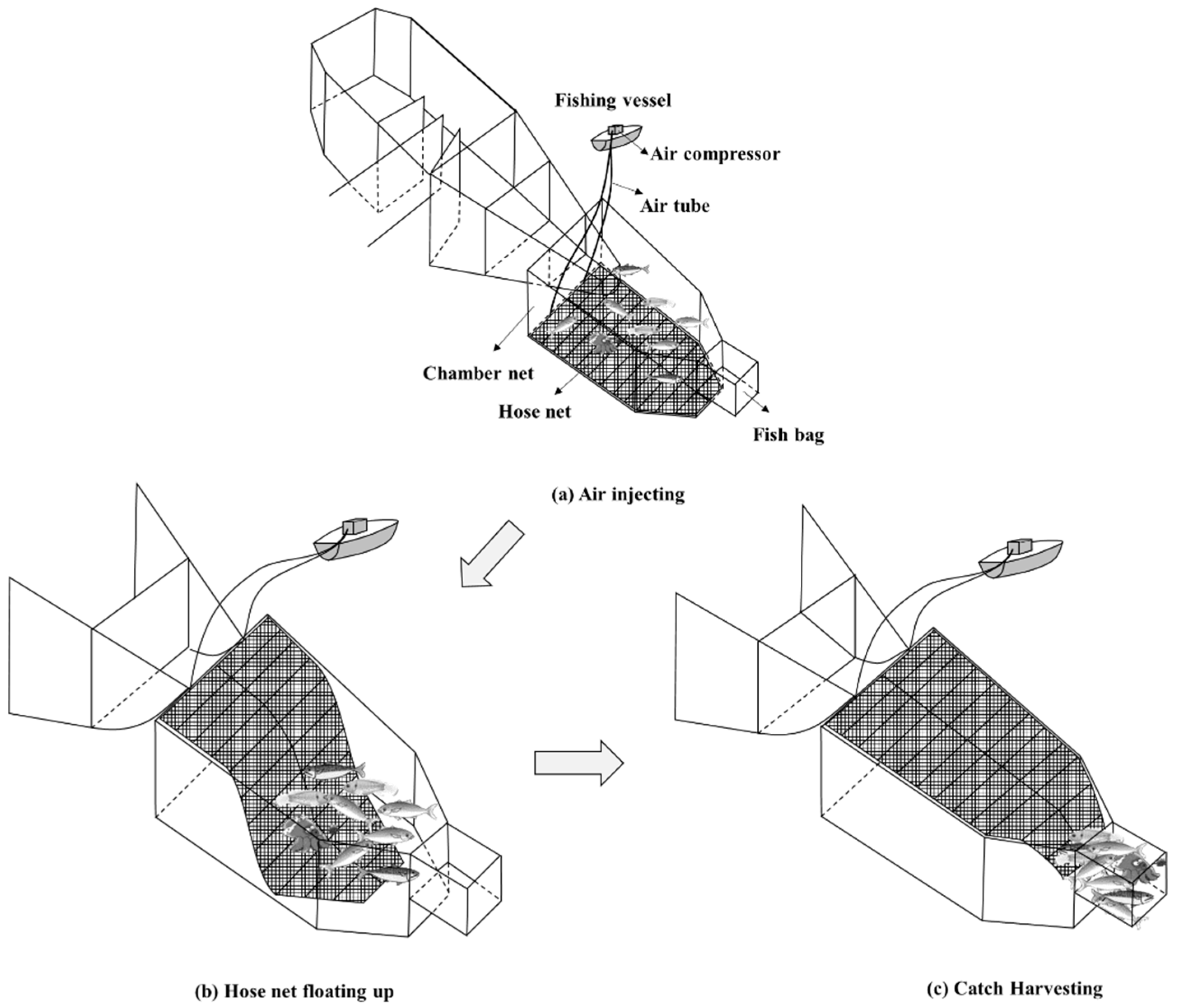
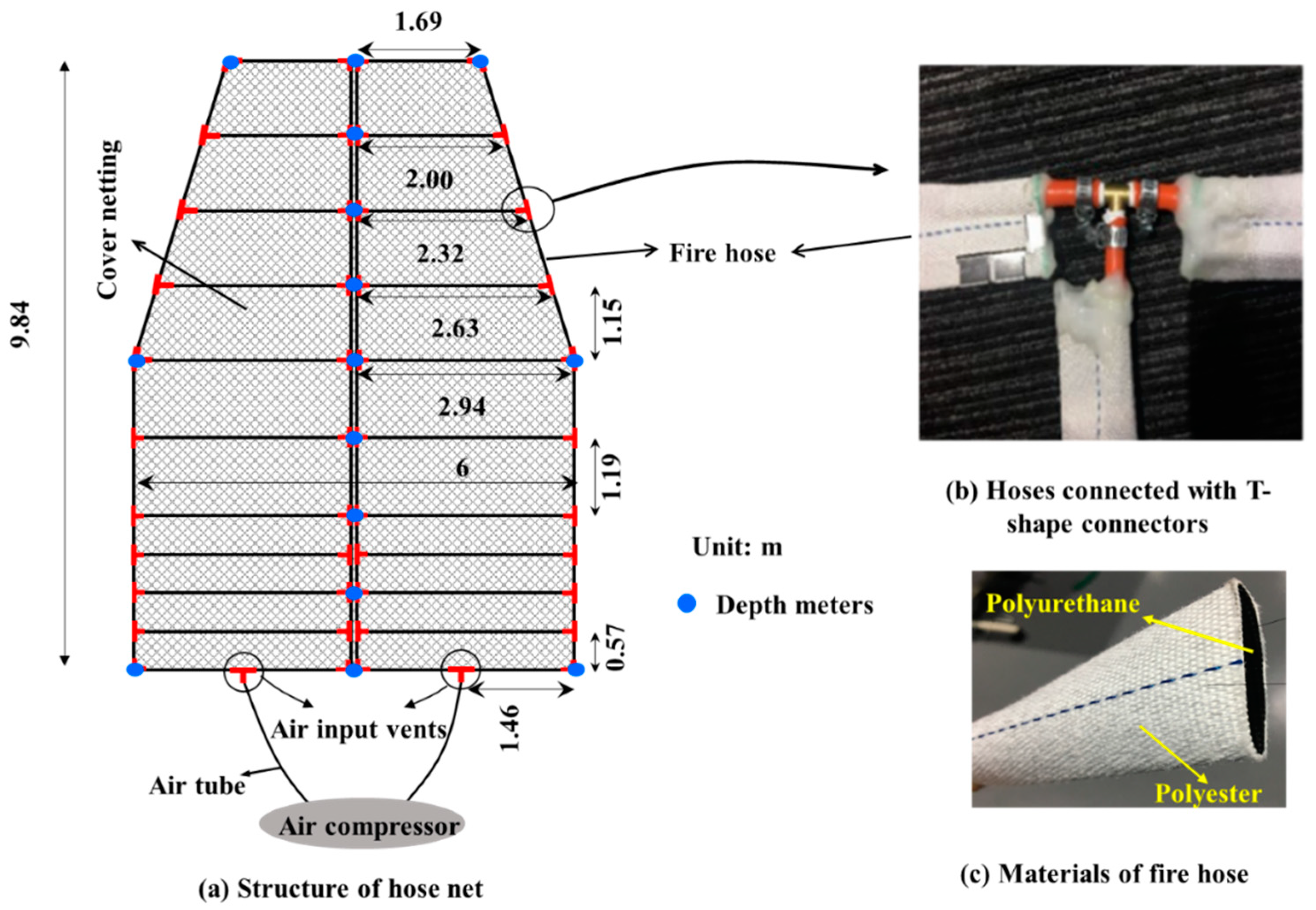
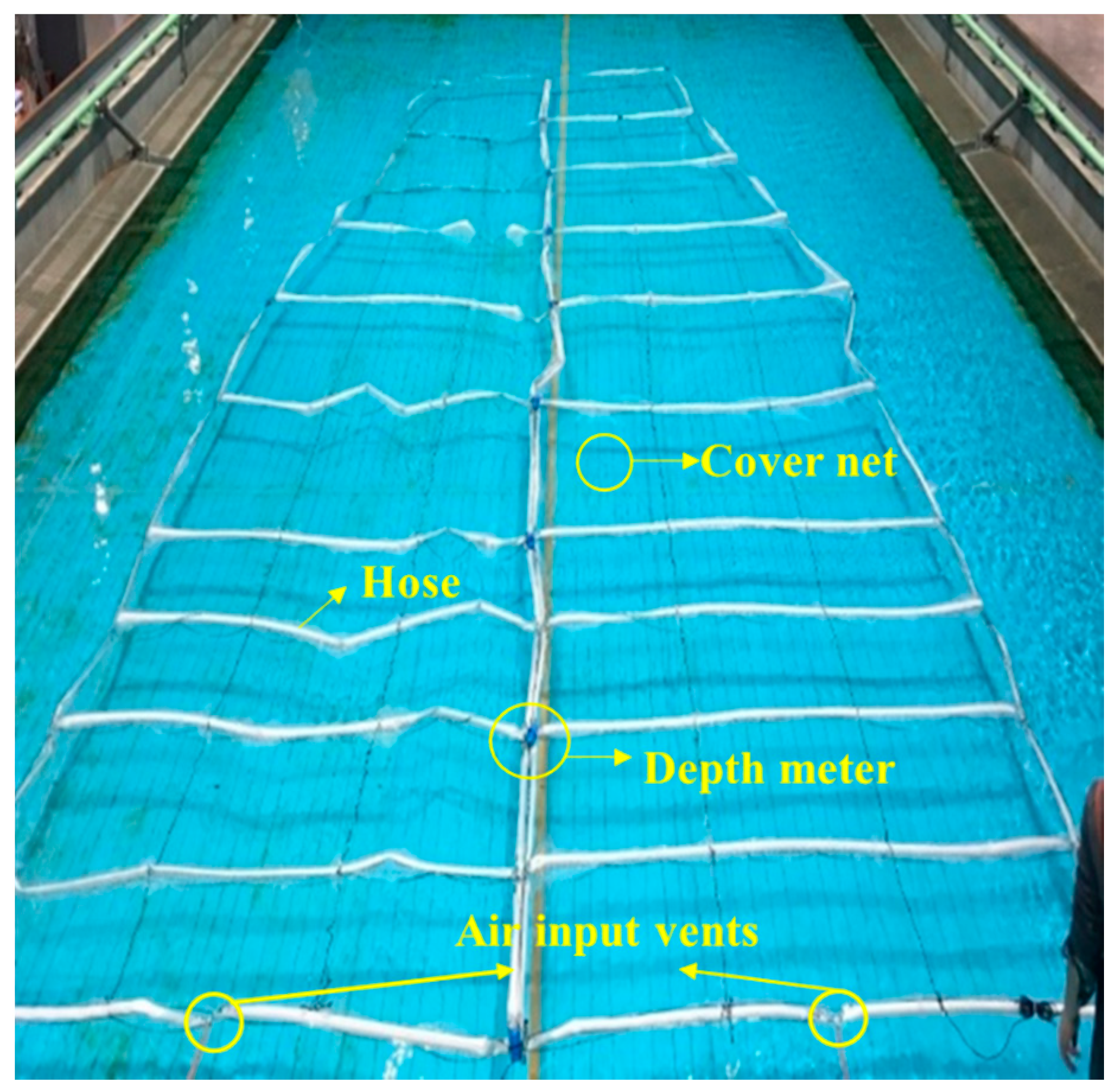
2.1.1. Novel Automated Catch-Hauling Device Model
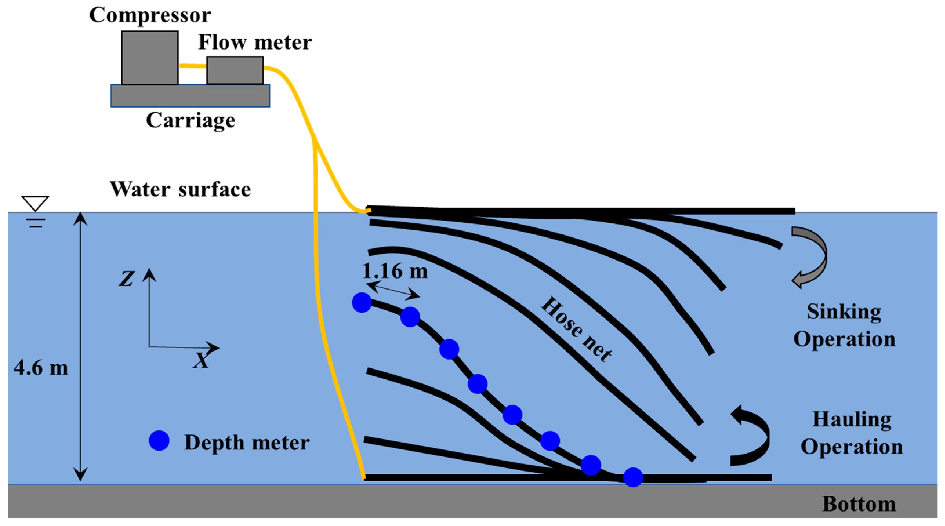
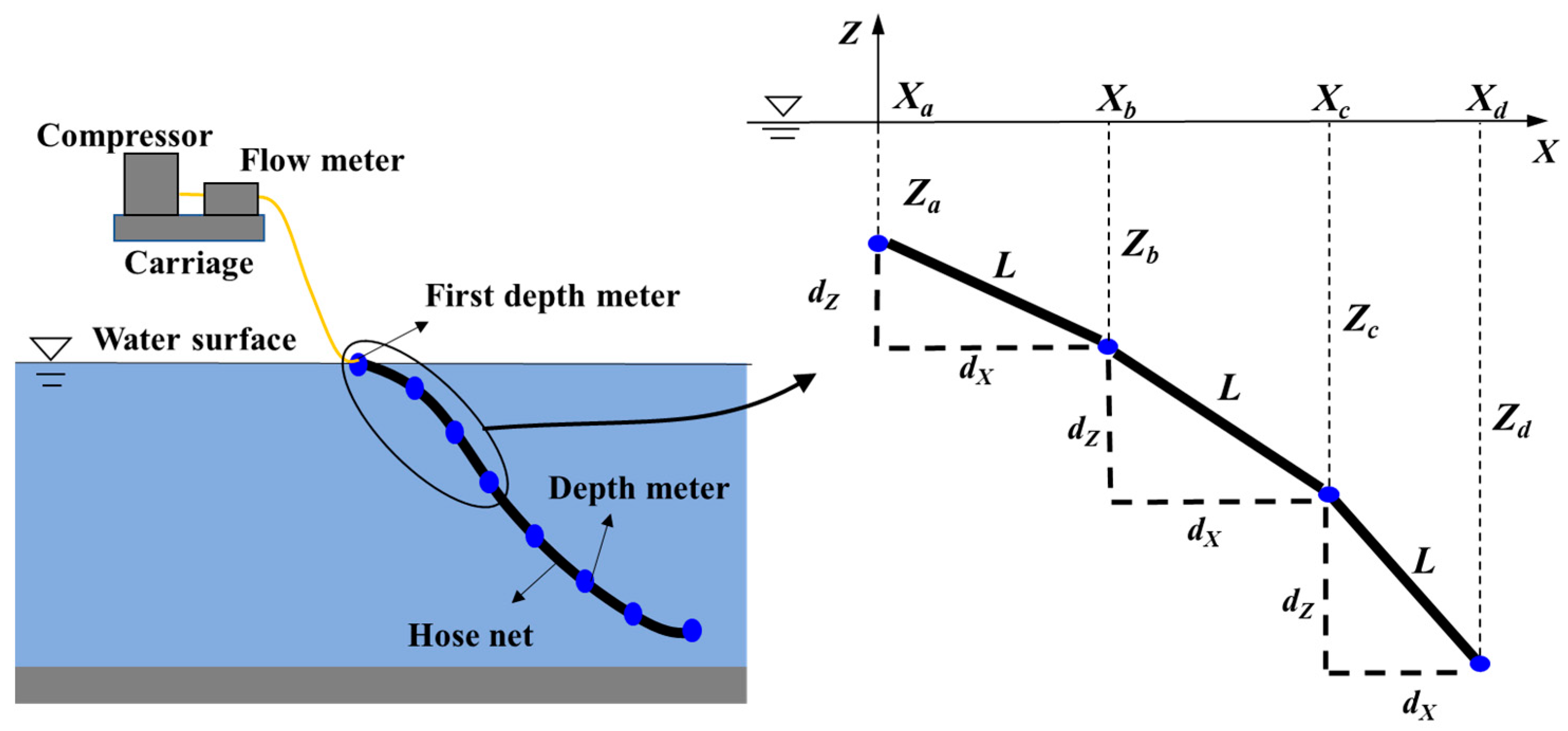
2.1.2. Experimental Measurements and Analysis
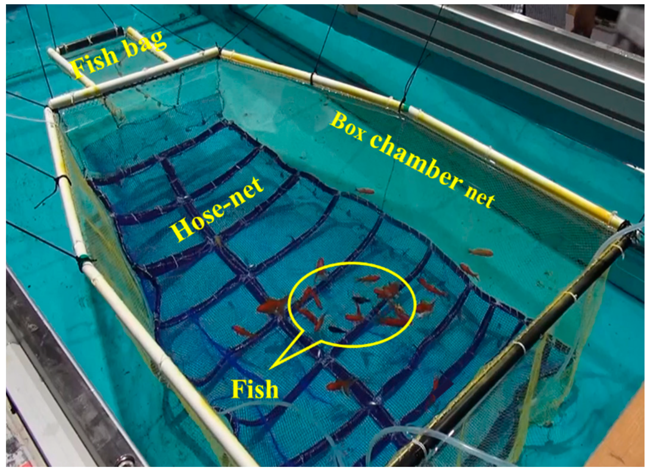
2.2. Catch-Hauling Tests Using Live Fish
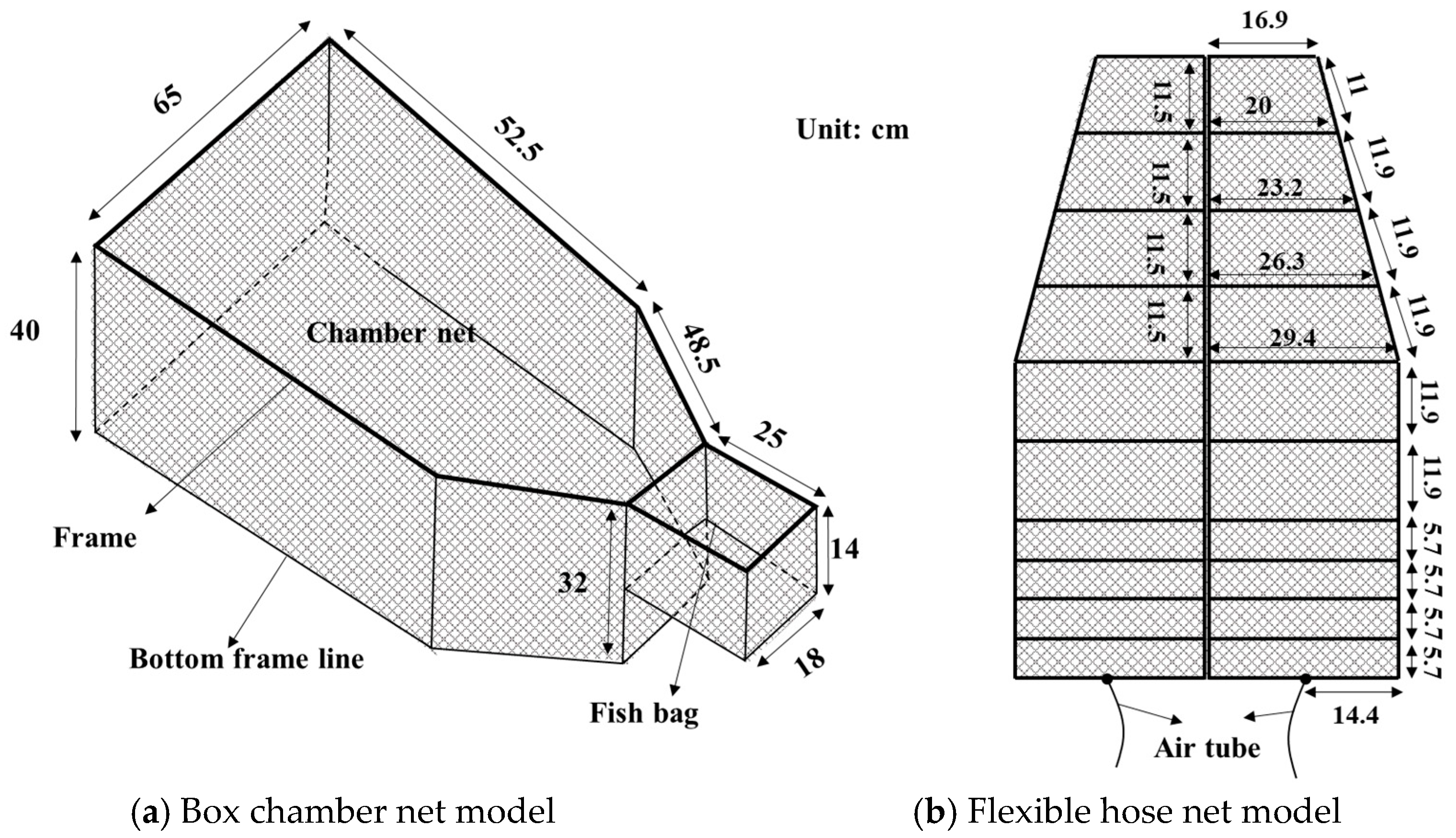
2.2.1. Box Chamber Net and Flexible Hose Net Models
2.2.2. Live Fish
2.2.3. Experimental Conditions
3. Results and Discussion
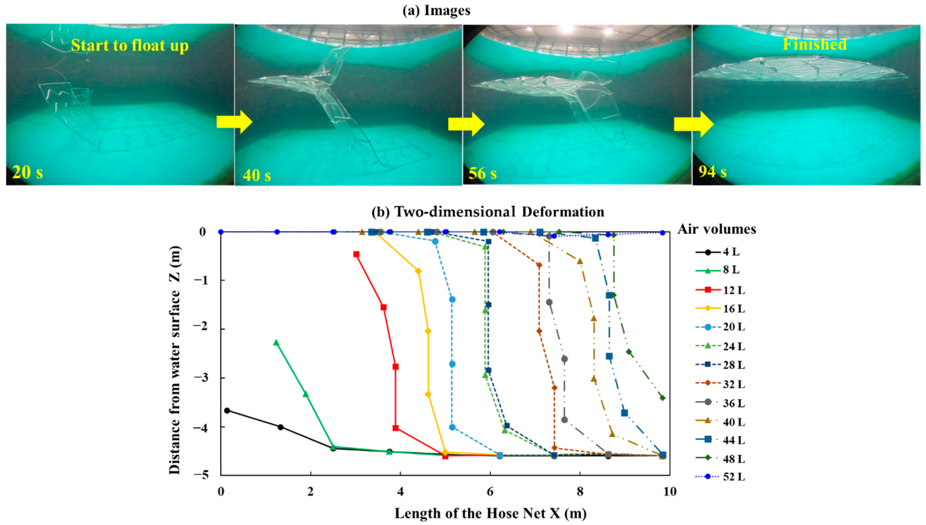
3.1. Effects of the Air Volumes on the Two-Dimensional Deformation of Hose Net
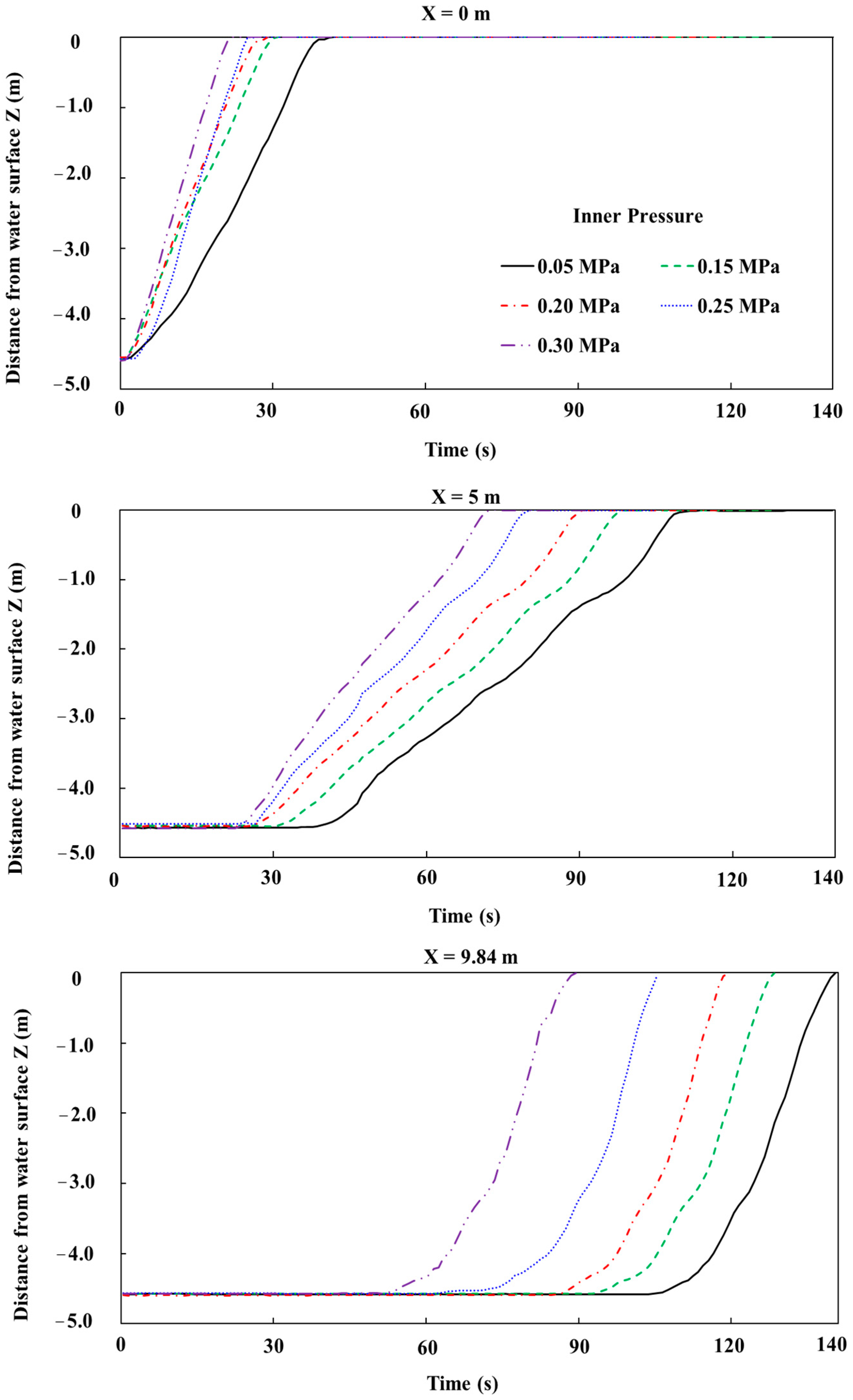
3.2. Effects of Initial Pressure of Air Compressor on the Floating Speed
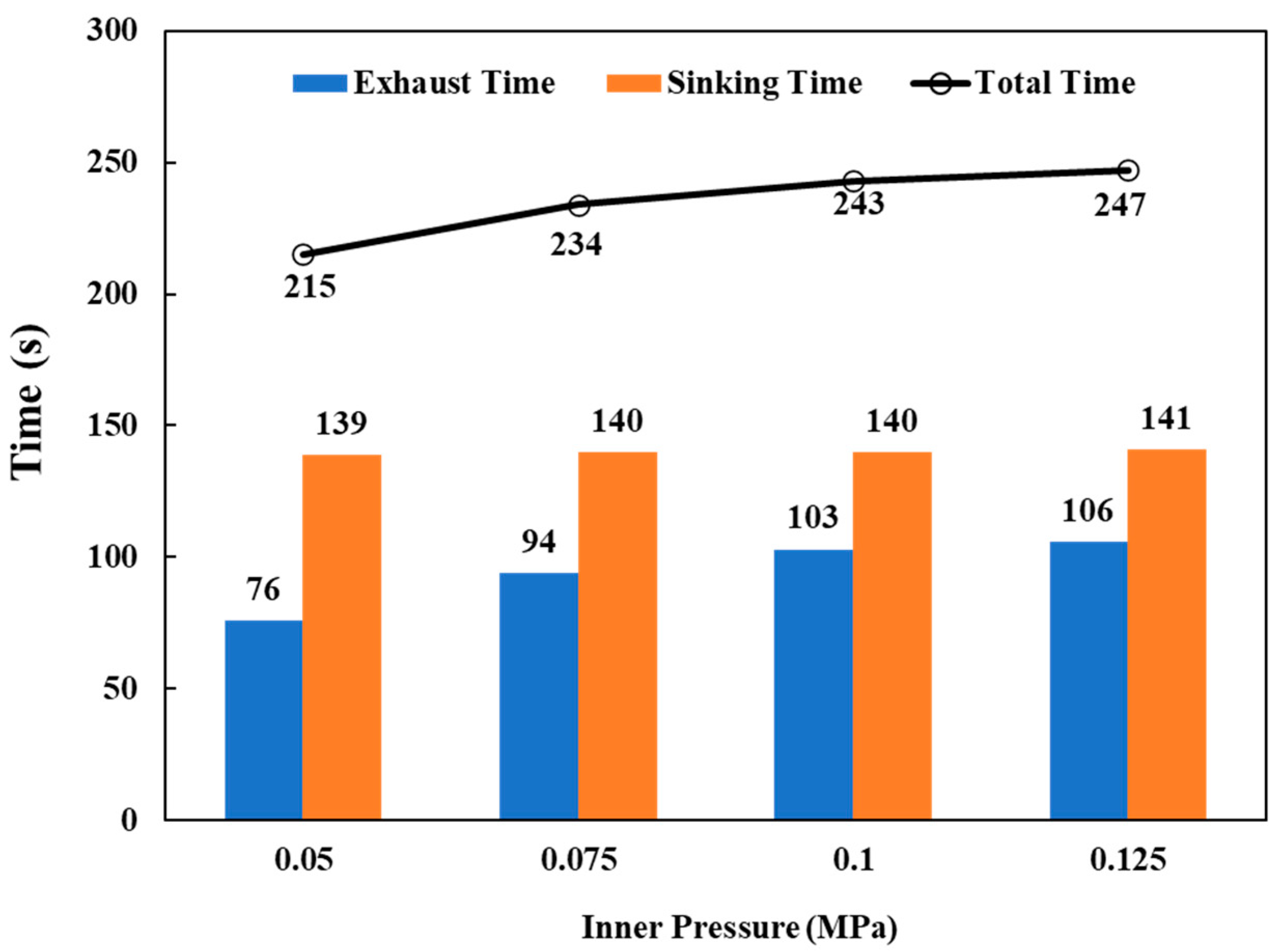
3.3. Effects of Initial Inner Pressure on the Time for Sinking Down
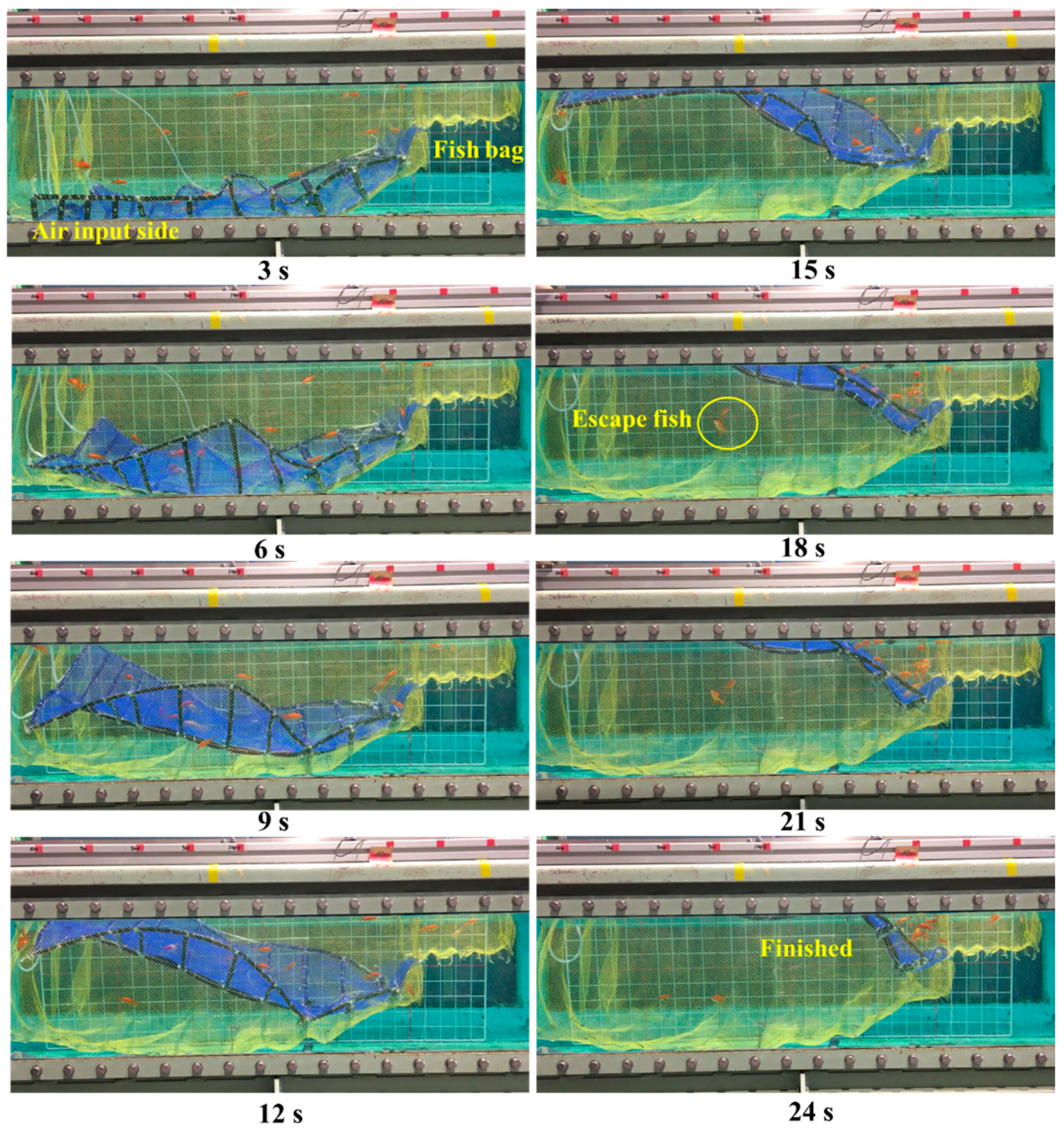
3.4. Catch-Hauling Performances
4. Conclusions
Author Contributions
Funding
Institutional Review Board Statement
Informed Consent Statement
Data Availability Statement
Acknowledgments
Conflicts of Interest
Ethics Statements
References
- He, P.G.; Chopin, F.; Suuronen, P.; Ferro, R.S.T.; Lansley, J. Classification and Illustrated Definition of Fishing Gears; FAO Fisheries and Aquaculture Technical Paper No. 672; FAO: Rome, Italy, 2021. [Google Scholar]
- He, P.G.; Inoue, Y. Large-scale fish traps: Gear design, fish behavior, and conservation challenges. In Behavior of Marine Fishes: Capture Processes and Conservation Challenges; He, P., Ed.; Wiley-Blackwell: Ames, IA, USA, 2010; pp. 159–181. [Google Scholar]
- Takahashi, Y.; Komeyama, K. Simulation of the capture process in set net fishing using a fish-schooling behavior model. Fish Sci. 2020, 86, 971–983. [Google Scholar] [CrossRef]
- Hiramoto, T. Historical changes of set net type in Sagami bay-2. Big set net type-(1). Bull. Kanagawa Prefect. Fish Exp. Stn. 1997, 2, 25–47. [Google Scholar]
- Wan, R.; Guan, Q.L.; Li, Z.G.; Hu, F.X.; Dong, S.C.; You, X.X. Study on hydrodynamic performance of a set-net in current based on numerical simulation and physical model test. Ocean Eng. 2020, 195, 106660. [Google Scholar] [CrossRef]
- Ministry of Agriculture, Forestry and Fisheries of Japan. Available online: https://www.maff.go.jp/j/tokei/census/gyocen_illust2.html (accessed on 2 June 2021).
- Ministry of Agriculture, Forestry and Fisheries of Japan. 2020 Fishery and Aquaculture Production Statistics. Available online: https://www.maff.go.jp/j/tokei/kouhyou/kaimen_gyosei/index.html (accessed on 1 July 2021).
- Suuronen, P.; Chopin, F.; Glass, C.; Løkkeborg, S.; Matsushita, Y.; Queirolo, D.; Rihan, D. Low impact and fuel efficient fishing—Looking beyond the horizon. Fish. Res. 2012, 119, 135–146. [Google Scholar] [CrossRef]
- Takagi, T.; Moritomi, Y.; Iwata, J.; Nakamine, H.; Sannomiya, N. Mathematical model of fish schooling behaviour in a set-net. ICES J. Mar. Sci. 2004, 61, 1214–1223. [Google Scholar] [CrossRef]
- Inoue, Y.; Watanabe, T. Fish behaviour in the capturing process of the one-trapped and the two-trapped set-net. Nippon Suisan Gakkaishi. 1986, 53, 1738–1744. [Google Scholar]
- Inoue, Y. Size and moving behaviour of fish schools around the set-net. Nippon Suisan Gakkaishi. 1987, 53, 1307–1312. [Google Scholar] [CrossRef]
- Uchida, K.; Ogawa, H.; Hasegawa, K.; Miyamoto, Y.; Noro, H.; Wada, Y.; Akiyama, S. Monitoring the behavior of young bluefin tuna Thunnus orientalis and yellowtail Seriola quinqueradiata in set nets using ultrasonic biotelemetry. Nippon Suisan Gakkaishi. 2018, 84, 14–22. [Google Scholar] [CrossRef]
- Fisheries Agency: The 1st Technology Workshop of Set Net Fishery. Available online: https://www.jfa.maff.go.jp/j/study/kenkyusidoka/teichi.html (accessed on 12 May 2021).
- Fukahori, K.; Kasutani, M.; Nishenokubi, H. On the development of an automatic setnet. Bull. Fac. Fish Nagasaki Univ. 1988, 64, 45–51. [Google Scholar]
- Zhang, J.B.; Dohi, M.; Yoshida, T.; Kitazawa, D. Investigating the utilization of polyethylene pipe for automated hauling system in set net fishery. Ocean Eng. 2021, 233, 109192. [Google Scholar] [CrossRef]
- Suuronen, P.; Siira, A.; Kauppinen, T.; Riikonen, R.; Lehtonen, E.; Harjunpää, H. Reduction of seal-induced catch and gear damage by modification of trap-net design: Design principles for a seal-safe trap-net. Fish. Res. 2006, 79, 129–138. [Google Scholar] [CrossRef]
- Hemmingsson, M.; Fjälling, A.; Lunneryd, S.G. The pontoon trap: Description and function of a seal-safe trap-net. Fish. Res. 2008, 93, 357–359. [Google Scholar] [CrossRef]
- Kitazawa, D.; Mizukami, Y.; Hirai, Y. Numerical analysis of the motion of a flexible hose net used for hauling a box chamber. In Proceedings of the ASME 2012 31st International Conference on Ocean, Offshore and Arctic Engineering, Rio de Janeiro, Brazil, 1–6 July 2012. OMAE2012-84151. [Google Scholar]
- Kitazawa, D.; Zhang, J.B.; Mizukami, Y.; Hirai, Y.; Hosokawa, T. Experimental study on the motion of a flexible hose net used for fish-harvesting in a set net fishery. J. Mar. Sci. Technol. 2018, 23, 620–632. [Google Scholar] [CrossRef]
- Zhou, X.; Mizukami, Y.; Yoshida, T.; Kitazawa, D. Motion analysis of flexible hose based on water tank experiment. In Proceedings of the ASME 2018 37th International Conference on Ocean, Offshore and Arctic Engineering, Madrid, Spain, 17–22 June 2018. OMAE2018-77597. [Google Scholar]
- Li, Y.; Mizukami, Y.; Yoshida, T.; Li, Q.; Han, J.L.; Kitazawa, D. Experimental Study on the Motion of a Flexible Hose Net Used in Automated Net-Hauling System. In Proceedings of the ASME 2019 38th International Conference on Ocean, Offshore and Arctic Engineering, Glasgow, Scotland, UK, 9–14 June 2019. OMAE2019-95670. [Google Scholar]
- Li, Q.; Li, Y.; Mizukami, Y.; Dong, S.C.; Yoshida, T.; Kitazawa, D. Experimental Study on Fish-Harvest Performance of the Flexible Hose Net. In Proceedings of the ASME 2020 39th International Conference on Ocean, Offshore and Arctic Engineering, Virtual, 3–7 August 2020. OMAE2020-18513. [Google Scholar]
- Zhang, J.B.; Kitazawa, D.; Taya, S.; Mizukami, Y. Impact assessment of marine current turbines on fish behavior using an experimental approach based on the similarity law. J. Mar. Sci. Technol. 2017, 22, 219–230. [Google Scholar] [CrossRef]


| Items | 1/6 Model | Actual Net |
|---|---|---|
| Length (m) | 9.840 | 59.000 |
| Width (m) | 6.000 | 36.000 |
| Inner diameter of the hose (m) | 0.025 | 0.150 |
| Outer diameter of the hose (m) | 0.028 | 0.168 |
| Volume (m3) | 0.044 | 9.504 |
| Maximum buoyancy (N) | 526.8 | 116,548.7 |
| Weight of the chains (N) | 224.0 | 48,384.0 |
| Weight of the hoses (N) | 93.7 | 20,239.2 |
| Weight of the cover net (N) | 12.6 | 3350.7 |
| 42.5% | 42.5% | |
| 17.8% | 17.8% | |
| 2.4% | 2.4% |
| Material | Density | Mesh Size | Twine Diameter | |
|---|---|---|---|---|
| Box chamber net | polyester | 1380 kg/m3 | 11.6 mm | 0.5 mm |
| Hose net | polyester | 1380 kg/m3 | 3.8 mm | 0.4 mm |
| Hose | rubber | 1522 kg/m3 | / | / |
| Chain | / | 21 g/m | / | / |
| Physical Parameters | Value |
|---|---|
| Diameter of the Hose (cm) | 0.8 |
| Maximum buoyancy (N) | 4.7 |
| Weight of the chains (in the air) (N) | 2.0 |
| Weight of chains/maximum buoyancy (%) | 42.5 |
| Weight of the hose net (in water) (N) | 0.8 |
| The remaining maximum buoyancy (N) | 1.9 |
| Species | Body Length (cm) | Weight (g) | Tail Beat Frequency (Hz) | Swimming Speed (m/s) |
|---|---|---|---|---|
| Japanese wakin goldfish (small) | 4 ± 0.5 | 4.2 ± 0.3 | 20 | 0.42–0.48 |
| Japanese wakin goldfish (big) | 7.2 ± 0.3 | 15 ± 0.5 | 15 | 0.62–0.68 |
| Fringetail goldfish | 5 ± 0.5 | 12 ± 0.5 | 8 | 0.22–0.26 |
| Pearl scale goldfish | 3 ± 0.5 | 3.5 ± 0.2 | 12 | 0.18–0.25 |
| Case | Case 1 (High) | Case 2 (Medium) | Case 3 (Low) | |
|---|---|---|---|---|
| Time | ||||
| Time for air input side floating up (s) | 5 | 10 | 20 | |
| Time for the rest part floating up (s) | 9 | 15 | 21 | |
| Total time for floating up (s) | 14 | 25 | 41 | |
| Average floating up speeds (m/s) | 0.03 | 0.02 | 0.01 | |
| Floating Speed | Air Input Side (X = 0) (m/s) | Middle Part (X = 5.0 m) (m/s) | Rear Side (X = 9.84 m) (m/s) | Average Floating Up Speed (m/s) | |
|---|---|---|---|---|---|
| Initial Pressure of Air Compressor (MPa) | |||||
| 0.05 | 0.11 | 0.06 | 0.12 | 0.03 | |
| 0.15 | 0.14 | 0.07 | 0.12 | 0.04 | |
| 0.20 | 0.16 | 0.07 | 0.12 | 0.04 | |
| 0.25 | 0.18 | 0.08 | 0.12 | 0.04 | |
| 0.30 | 0.21 | 0.09 | 0.12 | 0.05 | |
Publisher’s Note: MDPI stays neutral with regard to jurisdictional claims in published maps and institutional affiliations. |
© 2021 by the authors. Licensee MDPI, Basel, Switzerland. This article is an open access article distributed under the terms and conditions of the Creative Commons Attribution (CC BY) license (https://creativecommons.org/licenses/by/4.0/).
Share and Cite
Li, Q.; Li, Y.; Dong, S.; Mizukami, Y.; Han, J.; Yoshida, T.; Kitazawa, D. Performance and Feasibility Study of a Novel Automated Catch-Hauling Device Using a Flexible Hose Net Structure in Set-Net. J. Mar. Sci. Eng. 2021, 9, 1015. https://doi.org/10.3390/jmse9091015
Li Q, Li Y, Dong S, Mizukami Y, Han J, Yoshida T, Kitazawa D. Performance and Feasibility Study of a Novel Automated Catch-Hauling Device Using a Flexible Hose Net Structure in Set-Net. Journal of Marine Science and Engineering. 2021; 9(9):1015. https://doi.org/10.3390/jmse9091015
Chicago/Turabian StyleLi, Qiao, Yue Li, Shuchuang Dong, Yoichi Mizukami, Jialin Han, Takero Yoshida, and Daisuke Kitazawa. 2021. "Performance and Feasibility Study of a Novel Automated Catch-Hauling Device Using a Flexible Hose Net Structure in Set-Net" Journal of Marine Science and Engineering 9, no. 9: 1015. https://doi.org/10.3390/jmse9091015