Article

COLREGs: Compliant Dynamic Obstacle Avoidance of USVs Based on the Dynamic Navigation Ship Domain

College of Mechanical and Electrical Engineering, Qingdao University of Science and Technology, Qingdao 266061, China
*
Author to whom correspondence should be addressed.
J. Mar. Sci. Eng. 2021, 9(8), 837; https://doi.org/10.3390/jmse9080837
Submission received: 3 July 2021 / Revised: 27 July 2021 / Accepted: 28 July 2021 / Published: 1 August 2021
(This article belongs to the Special Issue Maritime Autonomous Vessels)

Abstract

:
Dynamic obstacle avoidance is essential for unmanned surface vehicles (USVs) to achieve autonomous sailing. This paper presents a dynamic navigation ship domain (DNSD)-based dynamic obstacle avoidance approach for USVs in compliance with COLREGs. Based on the detected obstacle information, the approach can not only infer the collision risk, but also plan the local avoidance path trajectory to make appropriate avoidance maneuvers. Firstly, the analytical DNSD model is established taking into account the ship parameters, maneuverability, sailing speed, and encounter situations regarding COLREGs. Thus, the DNSDs of the own and target ships are utilized to trigger the obstacle avoidance mode and determine whether and when the USV should make avoidance maneuvers. Then, the local avoidance path planner generates the new avoidance waypoints and plans the avoidance trajectory. Simulations were implemented for a single obstacle under different encounter situations and multiple dynamic obstacles. The results demonstrated the effectiveness and superiority of the proposed DNSD-based obstacle avoidance algorithm.

1. Introduction

Unmanned surface vehicles (USVs) can perform various applications in various science, civilian, and military fields, such as environmental monitoring [1,2,3] and military defense [4,5]. Furthermore, due to the advantages of low energy consumption and reduced labor costs [6], many countries are vigorously developing USVs [7,8]. According to the research of Baker and Seah [9], about 50% of marine accidents are caused by human errors, 30% of accidents should have been discovered and prevented by humans, and the other 20% are caused by uncontrollable factors such as damage to the vessel’s own equipment and hull and the harsh marine environment. USVs can avoid human errors and reduce losses by the use of intelligent obstacle avoidance systems. The process of obstacle avoidance can be divided into four steps: obstacle detection, decision making, avoidance path planning, and control [8]. Here, we focus on the decision making and avoidance path planning stages. The decision-making stage determines whether, when, and how the own ship (OS) should take avoidance actions [10]. If the decision is made to avoid some obstacles, the OS enters the avoidance path planning stage, where a local path planner is employed to determine the desired guidance command to attempt the avoidance action.
The approaches to infer the obstacle avoidance risk include the closest point of approach (CPA) method and the ship domain method. The CPA-based approach was proposed to estimate the collision risk based on the distance to the CPA (DCPA) and the time to the CPA (TCPA) [11,12]. However, the CPA-based methods are insufficient for collision risk estimation and evasive maneuver determination [13]. The concept of the ship domain was first proposed by Fujii and Tanaka [14] as a safe area that must be maintained around the USVs during navigation to avoid collisions with other ships or obstacles. Since then, various ship domains with different shapes and sizes have been developed using empirical, analytical, and knowledge-based approaches [13,15]. The International Regulations for Preventing Collisions at Sea (COLREGs) [16] released by the International Maritime Organization (IMO) defines universal guides for all types of vessels to execute avoidance maneuvers. All the vessels including USVs should obey COLREGs to sail at sea lawfully. Otherwise, nonstandard avoidance maneuvers may lead to confusion and potentially collision risk [4]. Thus, ship domains considering COLREGs have been proposed subsequently [17,18,19]. Referring to Szlapczynski and Szlapczynska [13], ship domains can be implemented in an encounter situation with four safety criteria (see Figure 1). Based on these criteria, ship domains are commonly used in obstacle avoidance alerting systems to assess the collision risk and answer whether and when to make evasive maneuvers [15,20,21]. However, studies about ship domains rarely answer the question of how to implement the local avoidance path planning to take appropriate avoidance actions.
The path planning for USV collision avoidance can be classified into two categories: global path planning and local path planning. The global path planning generates the guidance path concerning a map of the known environment and the target information, while the local avoidance path planning determines the local avoidance path according to the dynamic detected obstacle information [22]. At present, local path planning methods include deep learning [23], VO [24], and SBG [16]. A commonly used local path planning method is the velocity obstacles (VOs) method, which was first applied in the robot field [25] and has been extended to USV motion planning compliant with COLREGs [26]. The VO method defines a cone-shaped space on the obstacle and keeps the OS outside the space to avoid collisions with nearby obstacles [27]. However, for USVs moving in complex circumstances and against dynamic obstacles, the avoidance effect is hard to achieve [28]. Especially when the OS is located between multiple obstacles, the choice of speed and heading will be difficult [16].
Therefore, based on the set-based control algorithm proposed by Moe et al. [29,30], Myre [16] proposed set-based guidance (SBG) for the dynamic obstacle avoidance of USVs. SBG defines an inner safety area and an outer reaction area around the TS. Once the OS touches the reaction area, SBG will switch the OS to the obstacle avoidance mode and plan an avoidance path. The SBG algorithm overcomes the wiggling behavior caused by the VO when the velocity is between multiple obstacles and reduces the wear of the USVs. However, since the reaction and safety area are set as circles with constant radii, the radii cannot reflect the influences of the sailing speed and different encounter situations. This will result in a long avoidance trajectory and lead to a waste of energy.
Motivated by the aforementioned analysis, we propose to trigger the obstacle avoidance mode when the ship domains of the OS and TS overlap (Figure 1d) and execute an avoidance maneuver by ensuring that the OS does not violate the TS’s domain (Figure 1b). To overcome the drawback of the traditional SBG method, considering that the reaction distance of collision avoidance changes along with different COLREGs encounter situations (e.g., when the USV is under the head-on situation, the relative speed is greater, so it needs a larger reaction distance; while the relative speed of the overtaking situation is lesser, so it needs a smaller ship domain), the ship domain should be designed with a greater bow and lesser stern distance. Thus, this paper proposes a dynamic navigation ship domain-based (DNSD-based) dynamic obstacle avoidance algorithm for USVs. Firstly, the dynamic navigation ship domain (DNSD) is established, taking into account the ship parameters, maneuverability, sailing speed, and encounter situations. Secondly, in compliance with COLREGs, the DNSDs of the OS and TS are utilized instead of the constant circular reaction and safety area to conduct the obstacle avoidance process, including the mode switching between obstacle avoidance and path following, and the design of the local avoidance path planner. Simulations were implemented for a single obstacle under different encounter situations and multiple dynamic obstacles to verify the effectiveness and superiority of the proposed method.
The rest of the paper is arranged as follows: Section 2 briefly introduces the motion model of USVs and COLREGs. Section 3 introduces the modified dynamic navigation ship domain. Section 4 introduces the DNSD-based method and explains the implementation process. Section 5 implements the simulations and compares the results with the SBG method to verify the effectiveness and superiority of the proposed method. The conclusions are described in Section 6.

2. Preliminaries

2.1. Mathematical Model of USVs

For USVs, only the horizontal motion components of sway, surge, and yaw are considered. Two reference frames, the inertial Earth-fixed frame o x y z and the body-fixed frame o b x b y b z b attached to the moving vessel, are defined to build the motion model. Herein, the USV is rudderless with double thrusters; the thrust generated by the port and starboard thrusters is always in the same direction as the heading of the USV; there is no force generated by the rudder, so the sway force can be considered as zero [31]. The motion equation of USVs can be described as [32]:
η ˙ = J ( ψ ) v ,
M v ˙ = C ( v ) v D ( v ) v + τ ,
where η = [ x , y , ψ ] T is the position vector depicted in the Earth-fixed frame, including the north-east position ( x , y ) and the heading angle ψ . v = [ u , v , r ] T is the velocity vector depicted in the body-fixed frame, including the surge and sway velocities ( u , v ) and the yaw rate r. τ = [ τ u , τ r ] T is the surge and yaw control vector. M , C ( v ) , D ( v ) , and J ( ψ ) are the inertia matrix, Coriolis-centripetal matrix, damping matrix, and transfer matrix, respectively. The definitions are as follows:
J ( ψ ) = c o s ψ s i n ψ 0 s i n ψ c o s ψ 0 0 0 1 , M = m X u ˙ 0 0 0 m Y v ˙ Y r ˙ 0 Y r ˙ I z N r ˙ ,
C ( v ) = 0 0 c 13 0 0 c 23 c 13 c 23 0 , D ( v ) = d 11 0 0 0 d 22 d 23 0 d 32 d 33 ,
where m is the mass of the vessel, I z is the ship’s inertia about the z b -axis, c 13 = m v + Y v ˙ v + Y r ˙ r , c 23 = m u + X u ˙ u , d 11 = X u X u u | u | X u u u u 2 , d 22 = Y v Y v v | v | Y v v v v 2 , d 23 = Y r , d 32 = N v , d 33 = N r N r r | r | N r r r r 2 , and X ( · ) , Y ( · ) , and Y ( · ) are referred to as hydrodynamic derivatives.

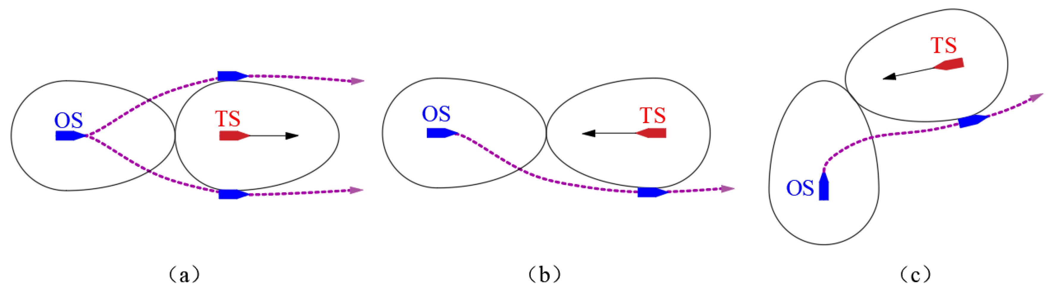
2.2. COLREGs in Collision Avoidance

COLREGs are mandatory for the operation of marine vessels. It is significant to develop evasion maneuvers based on COLREGs for USVs to ensure safety at sea. Since this paper is focused on whether the OS can achieve collision avoidance operation as a given vessel, the following rules for a variety of COLREGs encounter situations are used for USV collision avoidance:
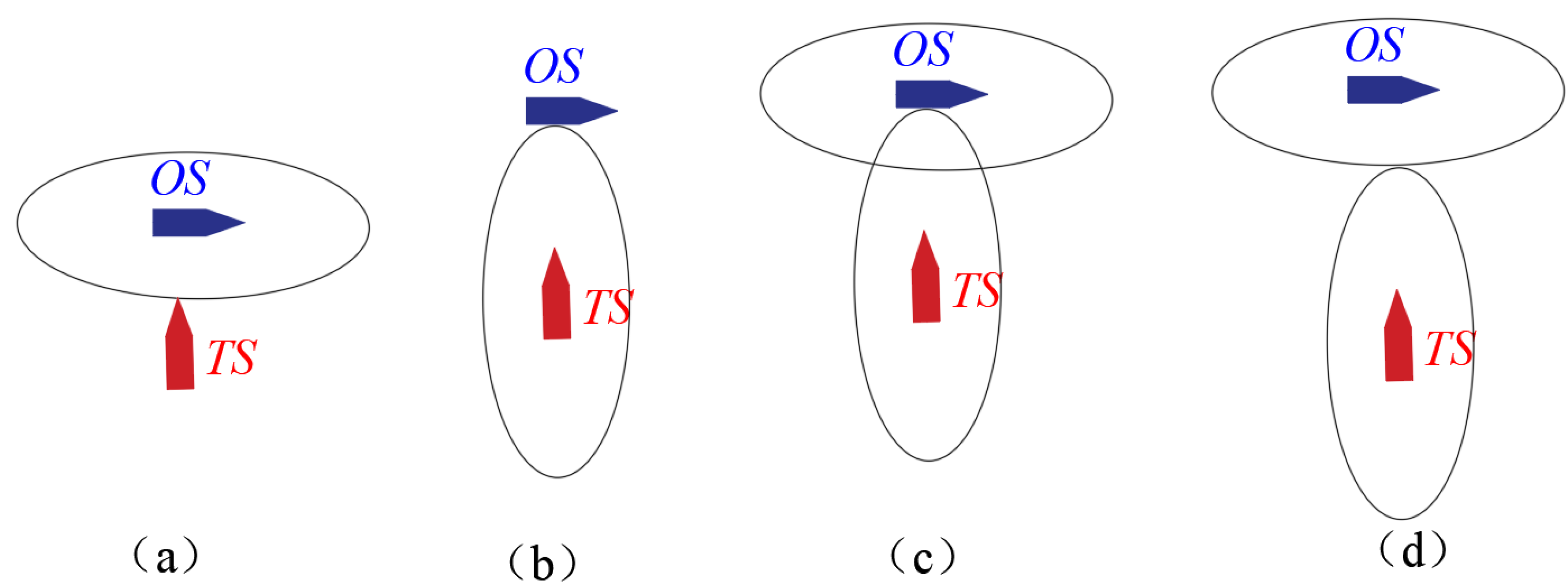
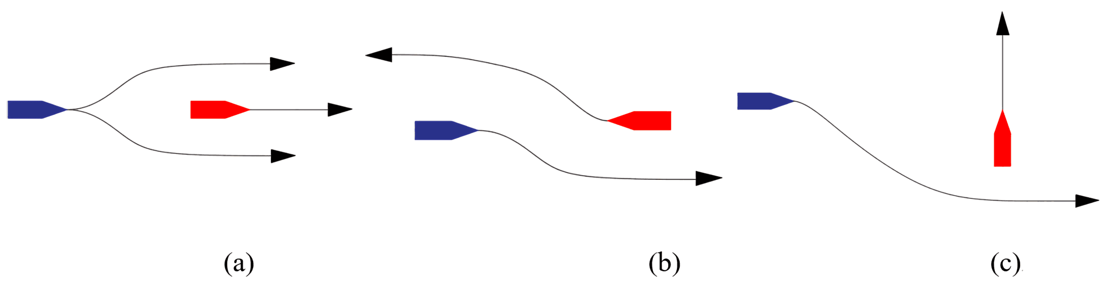
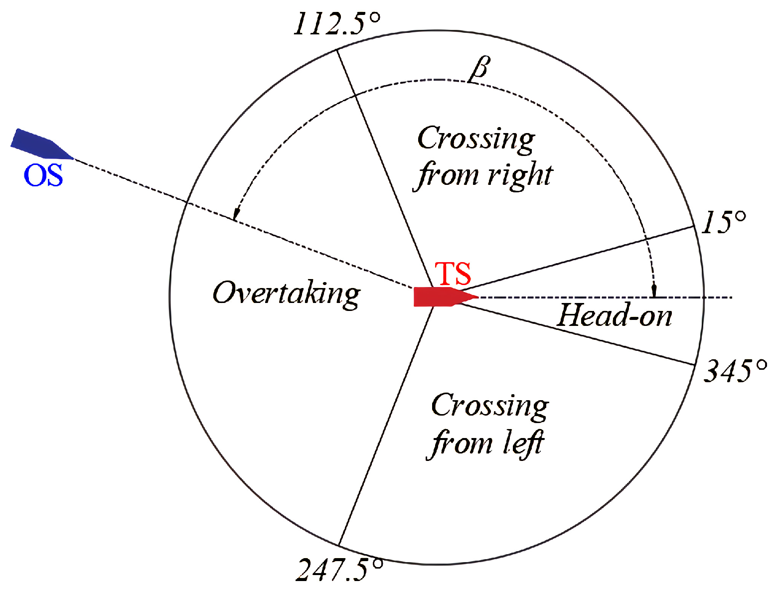
  • Rule 13 (overtaking): The OS shall be deemed to be overtaking when coming up to the target ship (TS) from a direction of more than 22.5 degrees abaft its beam. In this situation, the OS shall overtake the TS from either the port or the starboard side of the TS (see Figure 2a);
  • Rule 14 (head-on): When the OS and TS meet on reciprocal or nearly reciprocal courses, each shall alter its course to starboard (see Figure 2b);
  • Rule 15 (crossing): Crossing refers to two vessels encountering each other between the direction of 15 and 112 . 5 (port and starboard). The vessel that has the other on its starboard side shall keep out of the way (see Figure 2c).
In order to determine the encounter situation, the relative bearing angle β between the OS and TS is defined as shown in Figure 3. The head-on angle was chosen to be a total of 30 degrees wide around the heading of the TS; the crossing angle was selected as 97.5 degrees on each side; the remaining angle was regarded as overtaking. The relative bearing angle β is calculated as:
β = arctan y O S y T S x O S x T S ψ T S ,
where ψ T S is the heading of the TS and ( x O S , y O S ) and ( x T S , y T S ) are the position of the OS and TS, respectively.

3. Modified Dynamic Navigation Ship Domain

As mentioned above, the ship domain is a safe area that must be maintained around USVs. Motivated by the four safety criteria [13] and the SBG obstacle avoidance method [16], we propose to trigger an avoidance action when the ship domains of the OS and TS overlap (Figure 1d) and determine an avoidance maneuver by ensuring that the OS does not violate the TS’s domain (Figure 1b). The basic idea is that once the ship domain of the OS and TS intersects, this indicates that there is a risk of collision, and it is time for the OS to take evasive actions. Then, based on COLREGs, the local avoidance path planner will redefine the local avoidance waypoints and replan the navigation path to guarantee the OS keeps away from the TS’s domain. The ship domain should be taken as the general model contributing to navigation risk assessment and path planning. Thus, the generation of ship domains should take into account different ship-related factors, including the ship dimensions, sailing speed, maneuverability, encounter situations, and COLREGs.
The ship domains in the literature are usually represented as elliptical, circular, hexagonal, polygonal, and other irregular shapes [13]. As for the application to collision avoidance, the ship domain model is required to have a smooth curve; thus, we focus on the elliptical- and circular-type domains. Fujii and Tanaka [14] first proposed an elliptical-type model depending primarily on the ship length, regardless of other factors such as the encounter situation and the sailing speed. Coldwell et al. [17] further defined an elliptical model with different borders regarding COLREGs for overtaking and meeting (head-on and crossing), taking into account different safety distances for the bow and stern. However, this domain type was criticized by Szlapczynski and Szlapczynska [13] since a shorter port side dimension may cause a problem in the crossing situation. Considering the relative bearing with the TS, Goodwin [33] introduced a circular-type domain represented by three disparate segments. To improve the discontinuity of Goodwin’s domain, Davis et al. [18] further put forward a smoothed version of the original.
The above geometrical models lack analytical presentations and are essentially static models, so they cannot be reasonably used for collision risk assessment and decision making. Thus, Wang [20,34] proposed a dynamic quaternion ship domain (DQSD) for feasible application to navigational decision support systems. The DQSD is identified by the quaternion or combined ellipse containing four radii, e.g., fore, aft, starboard, and port. Factors such as maneuverability, speed, and course were taken into consideration. On this basis, Zhou et al. [19] proposed the basic navigation safety domain (BNSD) by putting the encounter situation coefficients carried out by Kijima and Furukawa [35] into the DQSD formula. However, since there are four radii that need to be determined, this type of ship domain is somewhat complicated when applied to path planning.
Based on the aforementioned analysis, taking into account factors such as the ship dimensions, sailing speed, maneuverability, encounter situations, and COLREGs, the modified dynamic navigation ship domain (DNSD) for USVs was created for application to dynamic obstacle avoidance and path planning. The DNSD is composed of a semi-ellipse and a semicircle, which are determined by only two radii, R f and R s , as shown in Figure 4. This model is easy in practice for local avoidance path planning. In order to create the ship body-fixed ship domain when implementing obstacle avoidance, the proposed ship domain was established in the x ¯ o ¯ y ¯ coordinates, which is located at the origin of the Earth frame. The x ¯ and y ¯ axes point toward the same direction as the x and y axes, respectively. The specific DNSD formula can be written as follows:
D N S D = ( x ¯ , y ¯ ) | f ( x ¯ , y ¯ ; Q ) 1 , Q = { R f , R s } ,
f ( x ¯ , y ¯ ; Q ) = 2 x ¯ ( 1 + s g n ( x ¯ ) ) R f + ( 1 s g n ( x ¯ ) ) R s 2 + 2 y ¯ ( 1 + s g n ( x ¯ ) ) R s + ( 1 s g n ( x ¯ ) ) R s 2 ,
where sgn ( · ) is the sign function defined as:
s g n ( x ¯ ) = 1 , x ¯ 0 ; 1 , x ¯ < 0 .
The elliptical and circular radii are determined taking into consideration the ship dimensions, the relative speed, the maneuverability, and the encounter situation regarding the relative bearing and COLREGs. The dynamic radii are described as:
R f = L + 0.67 ( 1 + s ( i ) ) A D 2 + ( D T 2 ) 2 , R s = B + D T ( 1 + t ( i ) ) ,
with:
s ( i ) = | 2 U U 0 | , t ( i ) = 0.2, i = h e a d o n ; 2 β π , t ( i ) = β π , i = c r o s s i n g ; 1 , t ( i ) = 0.2, i = o v e r t a k i n g .
where L and B are the ship’s length and width, respectively. A D is the advance distance, which represents the longitudinal forward distance of the center of gravity in the case of the vessel turning 90 from the start of steering. D T is the tactical diameter, which represents the transverse distance of the center of gravity in the case of the vessel turning 180 from the start of steering. U is the relative speed represented by U O S U T S , and U O S and U T S are the speeds of the OS and TS, respectively. s ( i ) and t ( i ) are the coefficients reflecting encounter situations regarding COLREGs, including head-on, crossing, and overtaking.

4. COLREGs-Compliant Dynamic Navigation Ship Domain-Based Dynamic Obstacle Avoidance

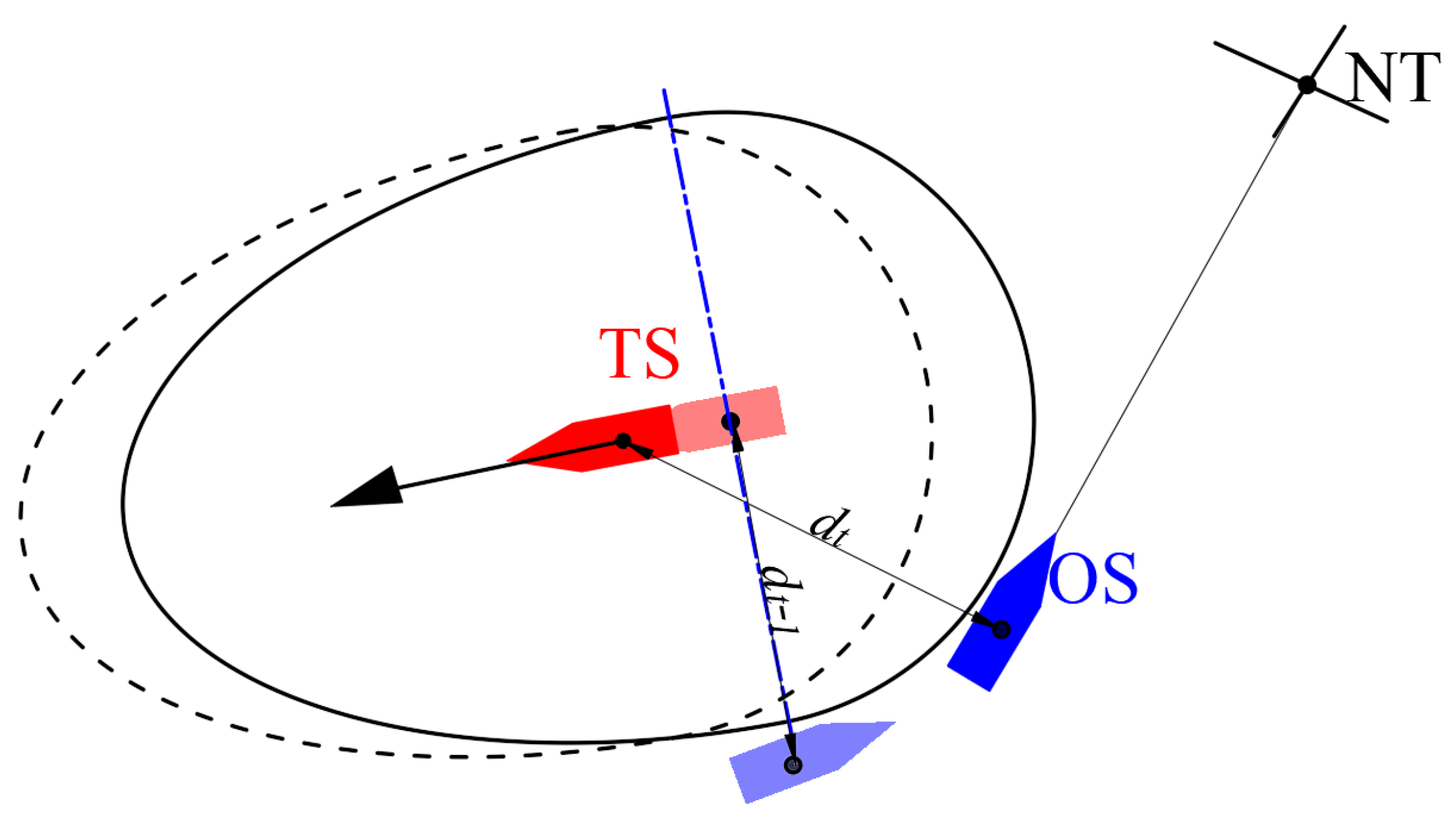
4.1. Obstacle Avoidance Time Inference

To execute the proposed dynamic navigation ship domain-based (DNSD-based) dynamic obstacle avoidance method, an assumption is made that the dimensions of the TSs and the navigation states including the sailing speed and heading should be acquired by the AIS or sensor system. Then, the DNSD of the TS can be accurately defined by the OS. Thus, when the ship domains of the OS and TS intersect, the obstacle avoidance algorithm infers that it is time to take evasive maneuvers, and the decision-making system will switch the OS to the obstacle avoidance mode. Then, the local avoidance path planning algorithm will determine the new waypoints in compliance with COLREGs. The schematic diagram of the proposed obstacle avoidance method is illustrated in Figure 5, from which we can see that the avoidance response distance dynamic changes regarding the different collision risks under different encounter situations and sailing speeds. For example, the response distance for overtaking is shorter than that for the head-on situation, since the relative speed in the overtaking situation is smaller. As for the crossing situation, the response distance will be different for different relative bearing angles. Furthermore, a higher sailing speed will result in a larger response distance as well.
To judge whether the ship domains intersect, the body-fixed ship domain of the OS and TS should be created. Firstly, the ship domain defined in the x ¯ o ¯ y ¯ coordinates should be rotated around the origin, making the x ¯ axis point to the heading of the ship. Then, the ship domain should be translated to the origin of the body-fixed frame o b x b y b z b . By defining the coordinate rotation matrix:
Z ( ψ ) = cos ψ sin ψ sin ψ cos ψ .
the ship domain curve can be obtained as:
x y D N S D , i = x ¯ y ¯ D N S D , i × Z ( ψ i ) + x i y i , i = { O S , T S }
where ( x D N S D , y D N S D ) are the coordinates of the ship domain in the Earth frame.
In addition, for multiple obstacles, the distance to the closest point of approach (DCPA) was adopted to determine the most dangerous obstacle. The TS with the minimum DCPA will be selected as the most dangerous obstacle, toward which the OS will first take avoidance actions. By using the “Solve” function, the intersection point can be found. The collision risk assessment process can be described as:
R S K = 1 , D N S D s i n t e r s e c t ; 0 , D N S D s n o t i n t e r s e c t .
Thus, when R S K = 1 , the system trigger switches to obstacle avoidance mode; otherwise, it remains in the original path following mode.

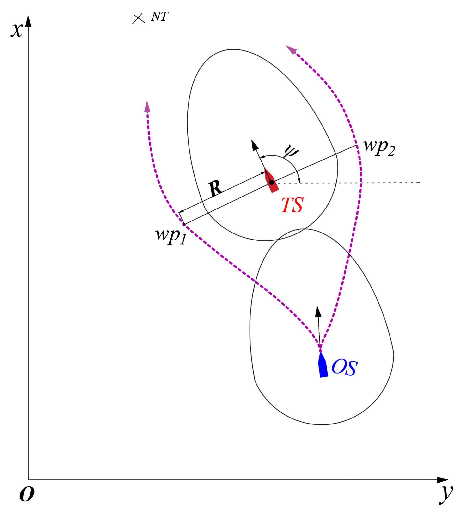
4.2. Local Avoidance Path Planning

When the OS switches to obstacle avoidance mode, a local avoidance path planning process will run to replan the avoidance trajectory. The process is as follows:
(1)
Determine the encounter situation regarding COLREGs
The COLREGs encounter situation between the OS the TS can be determined by calculating the relative bearing angle β . According to Figure 3, for different β , the OS can make the corresponding avoidance maneuvers of head-on, overtaking, cross from right, or cross from left;
(2)
Decide which side to pass on
Regarding COLREGs, for the head-on or crossing situation, the OS shall choose to pass from the port side of the TS. For the overtaking situation, the OS can pass from either the starboard side or the port side of the TS. The overtaking direction is determined regarding the position of the next target point relative to the TS. If the next target is located at the starboard side of the TS, then the OS should pass from the starboard side; otherwise, it passes from the port side;
(3)
Generate the avoidance waypoints and trajectory
To replan the avoidance trajectory, the OS needs to find new obstacle avoidance waypoints for evasive maneuvers. The method to find the new waypoints is illustrated in Figure 6, where NT represents the next target point. The new waypoint is related to the heading ψ T S of the TS; when the OS chooses to pass from the port side, then the waypoint w p 1 shall be selected; otherwise, if it passes from the starboard side, the waypoint w p 2 shall be selected. The positions of w p 1 and w p 2 can be calculated as:
x w p 1 = x T S + R cos ψ T S y w p 1 = y T S R sin ψ T S
and:
x w p 2 = x T S R cos ψ T S y w p 2 = y T S + R sin ψ T S
respectively, where:
R = r 1 × R s ( O S ) + r 2 × R s ( T S ) ,
is a parameter adjusting the position of the new waypoints; it is adjusted by r 1 and r 2 , which are constants between ( 0 1 ) . Once the USV has switched to obstacle avoidance mode, the new waypoints shall be inserted into the original global waypoints. Then, the new waypoints will be used to generate the avoidance trajectory.

4.3. Mode Switching to Path Following

Under obstacle avoidance mode, the OS will make avoidance maneuvers in accordance with COLREGs and the replanned path trajectory, then the collision risk will gradually reduce. Thus, it is necessary to judge when to finish obstacle avoidance mode and switch back to path following mode. The obstacle avoidance model is executed when the ship domains of the OS and TS intersect; if we switch out of this mode when the ship domains do not overlap, it will result in a long and unnecessary avoidance path trajectory. Hence, we used a more reasonable method to determine when to finish obstacle avoidance mode. As shown in Figure 7, when the OS has passed the juncture of the semi-ellipse and semicircle of the TS domain and the current distance between the OS and TS is greater than that of the previous moment ( d t > d t 1 ) , obstacle avoidance mode should switched to path following mode, such that the OS will trace the next target point.

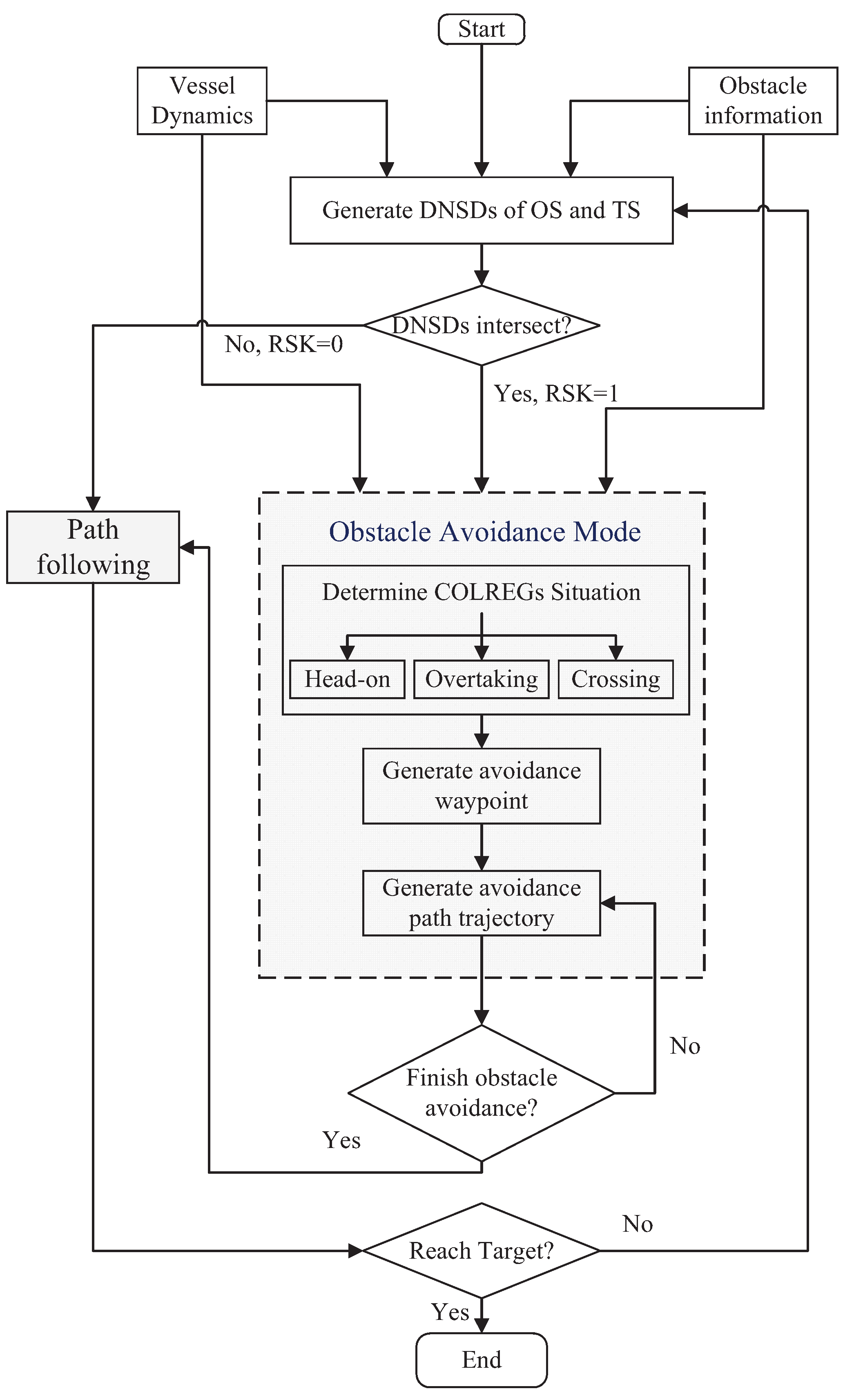
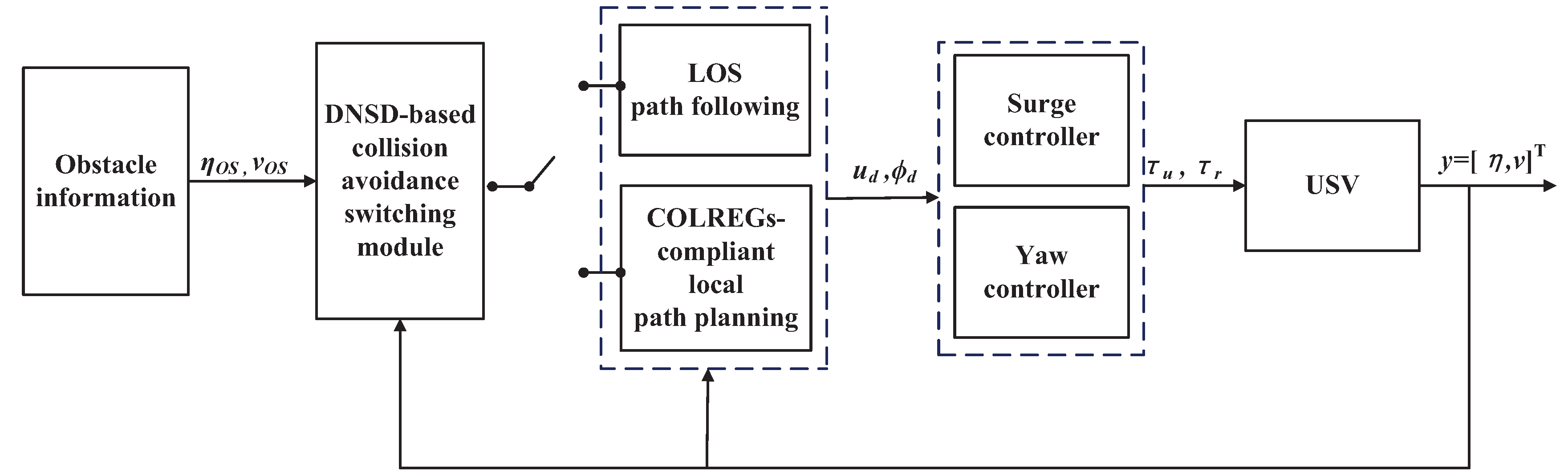
4.4. Implementation of the DNSD-Based Method

The programming process of the proposed DNSD-based obstacle avoidance method is shown as follows:
  • Calculating the DCPA between the OS and TSs and choosing the TS with the smallest DCPA as the most dangerous TS;
  • Determining the COLREGs encounter situation by calculating the relative bearing angle according to (5);
  • Determining the shape of the DNSDs of the OS and TSs in the x ¯ o ¯ y ¯ coordinates according to Equations (6)–(10);
  • Transforming the DNSDs along with the position and heading of the ships according to Equations (11)–(12);
  • Assessing the collision risk by (13) and determining the navigation mode: obstacle avoidance or path following;
  • Determining the new obstacle avoidance waypoint according to COLREGs using (14) or (15);
  • Determining whether to finish obstacle avoidance; if not, return to Step 6; otherwise, switch to path following mode;
  • Repeat the above steps until the target point is reached.
The flowchart of the DNSD-based obstacle avoidance algorithm is illustrated in Figure 8.

5. Simulation and Discussion

Aiming to verify the effectiveness of the proposed DNSD-based obstacle avoidance algorithm for USVs, simulations were implemented with MATLAB Simulink. The ship chosen for simulation was based on the Viknes830 [16]. The priority dynamic parameters for Viknes830 are shown in Table 1. To perform the obstacle avoidance simulations for USVs, the path planning and control stages must be considered as well. As such, we adopted the line-of-sight (LOS) guidance algorithm for path following and the surge and yaw controller to track the guidance command [16]. The LOS calculates the command heading according to the target point or obstacle avoidance point, then the surge and yaw controller will control the USV to sail along the direction of the command heading [36,37]. Thus, the control performance will affect the efficiency of collision avoidance. The block diagram of the obstacle avoidance and control system is illustrated in Figure 9.

5.1. Simulation Scenarios and Parameter Setting

In compliance with COLREGs, the obstacle avoidance behavior with a single TS and multiple TSs was validated. For the single TS situations, three different scenarios, including head-on, crossing, and overtaking, were considered in accordance with COLREGs. For the multiple TS situation, three TSs were taken into account, each of them representing the head-on, crossing, or overtaking situation, respectively.
The TSs were supposed to have identical parameters to the OS and constant velocities and heading throughout the simulations and would not give way under normal circumstances. The motion parameter setting for the OS and TSs is shown in Table 2. When conducting the local avoidance path planning process, the avoidance waypoints need to be calculated by Equations (14)–(16), where the values of r 1 and r 2 were determined by trial and error. Herein, we demonstrate that the collision avoidance performance was the best when r 1 = 0.8 and r 2 = 0.9 in the crossing and head-on situations and r 1 = 0.5 and r 2 = 0.6 in the overtaking situation.

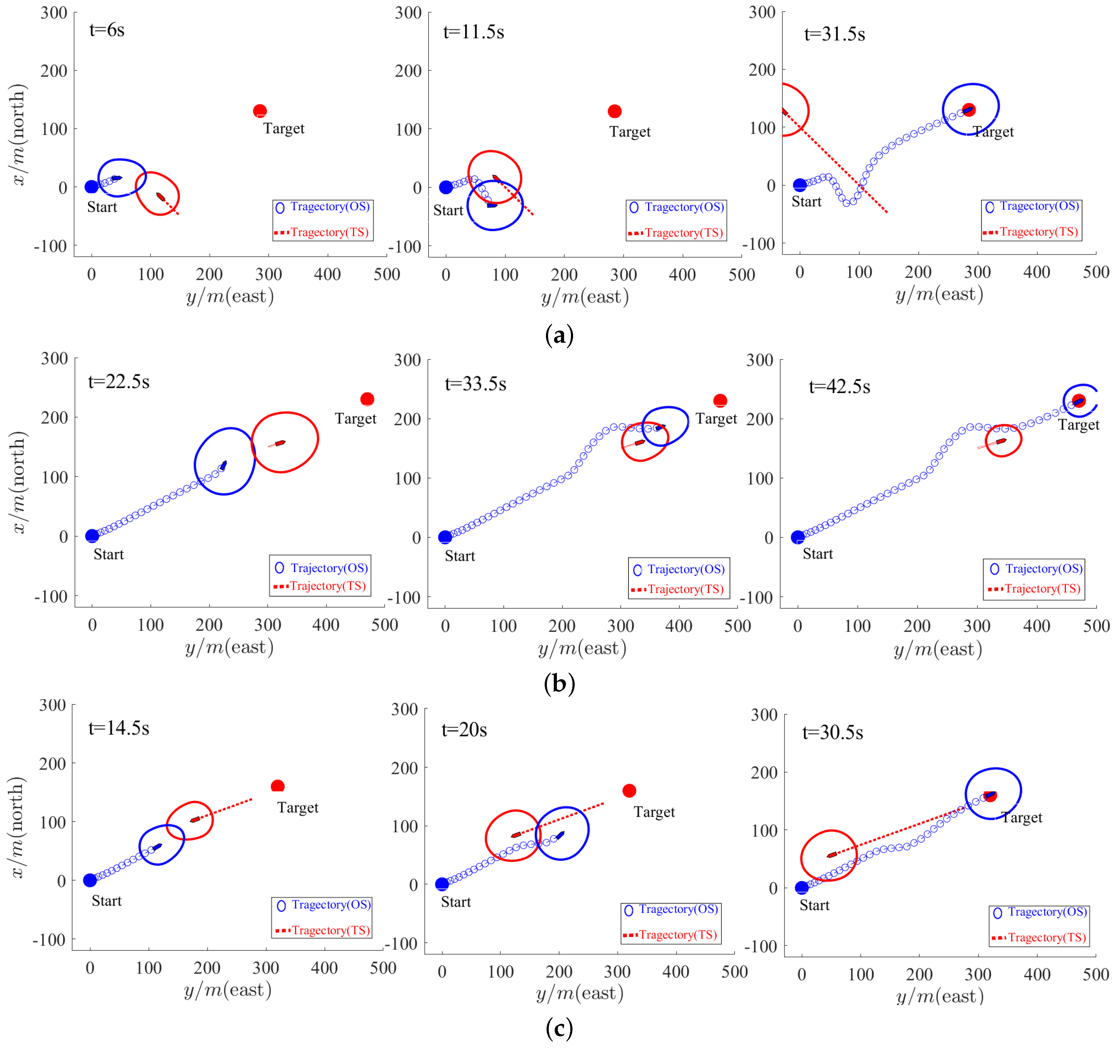
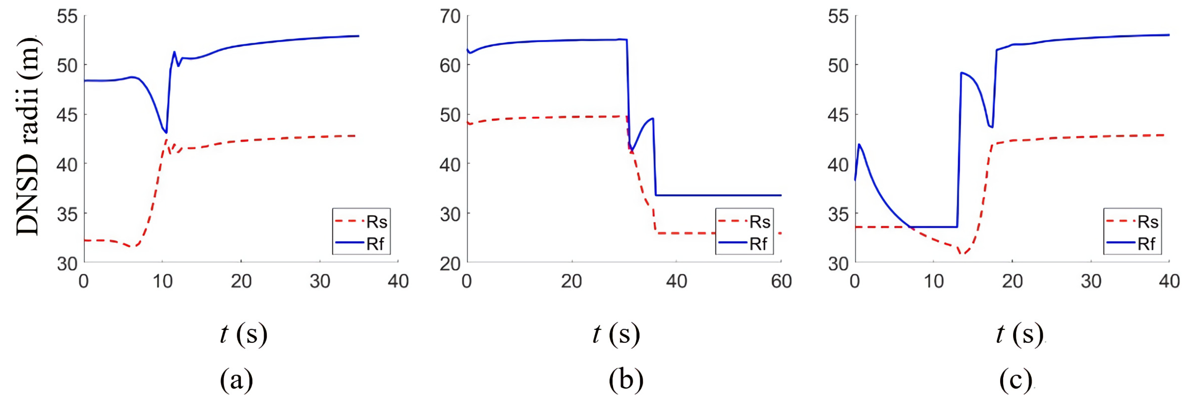
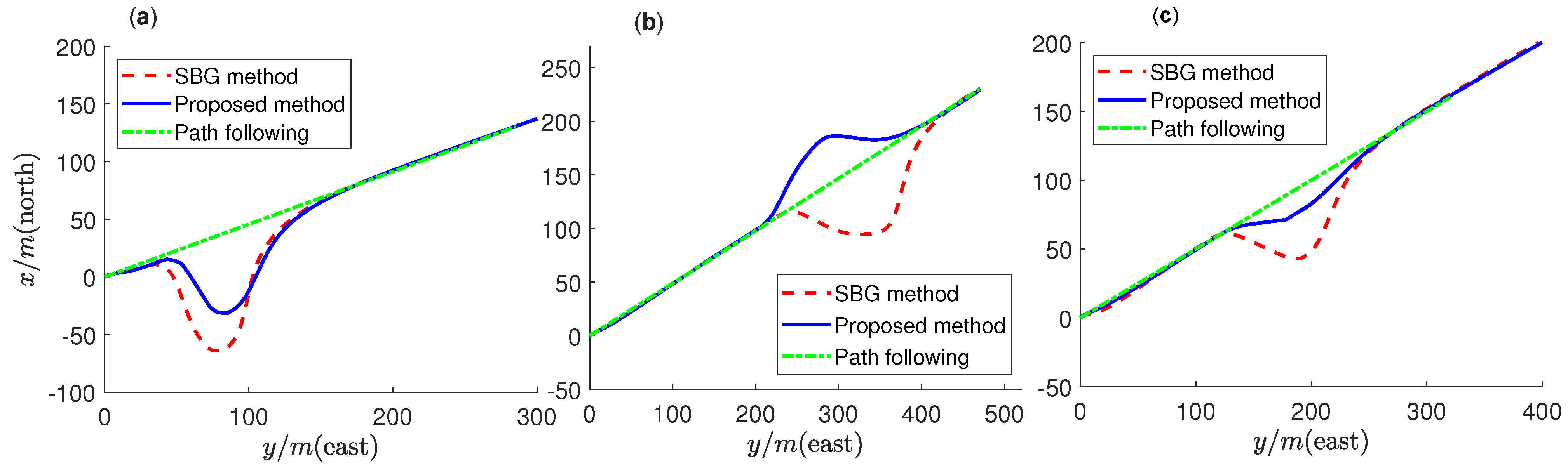
5.2. Single Obstacle Avoidance Performance Verification

Simulations were implemented for single obstacle avoidance using the proposed DNSD-based collision avoidance algorithm. The simulation results are illustrated in Figure 10. In the figure, the blue boat and solid circle represent the OS and the ship domain of the OS, respectively; the red boat and solid circle represent the TS and the ship domain of the TS, respectively. The blue dot represents the starting point of the OS, and the red dot represents the target point of the OS.
The simulation results of the crossing situation are shown in Figure 10a. It can be seen that at t = 6 s, the ship domains of the OS and TS intersected, then the OS switched to obstacle avoidance mode. The local avoidance path planner determined the new way points, and the OS made the avoidance maneuver according to COLREGs’ crossing rule. The avoidance path ensured that the OS did not violate the TS’s ship domain. Furthermore, we can see that at t = 11.5 s, when the OS went away from the TS ship domain, the OS was assessed to be safe with respect to the TS and then switched back to the original path following mode. This greatly accelerated the avoidance efficiency. Finally, when t = 31.5 s, the OS reached the target point. Similarly, the simulation results of the overtaking and head-on situations are shown in Figure 10b,c, respectively. The simulation results demonstrated the effectiveness of the DNSD-based collision avoidance for a single dynamic obstacle.
In addition, we note that both ship domains of the OS and TS were dynamically changing along with the speed and the encounter situation. The radii change curves of the OS ship domain for the crossing, overtaking, and head-on situations are shown in Figure 11a–c, respectively. It can be seen that when the OS and TS were at a high risk of collision, in order to reduce the collision risk and execute a more reliable avoidance maneuver, the ship domain dimensions R f and R s enlarged in accordance with the corresponding encounter situations. Otherwise, when the vessels were at a relative low risk of collision, the ship domain dimensions shrank to improve the avoidance efficiency.
To verify the superiority of the proposed DNSD-based obstacle avoidance method, we compared the avoidance path trajectory with the SBG method proposed in [16]. As shown in Figure 12a–c, the length of the avoidance path for the crossing, overtaking, and head-on situations under the DNSD-based method was shorter than that under the SBG method. This indicates that the proposed DNSD-based method can perform a more accurate and efficient avoidance maneuver and can quickly switch back to path following mode. This can reduce the energy consumption and the wear and tear of the thrust system.

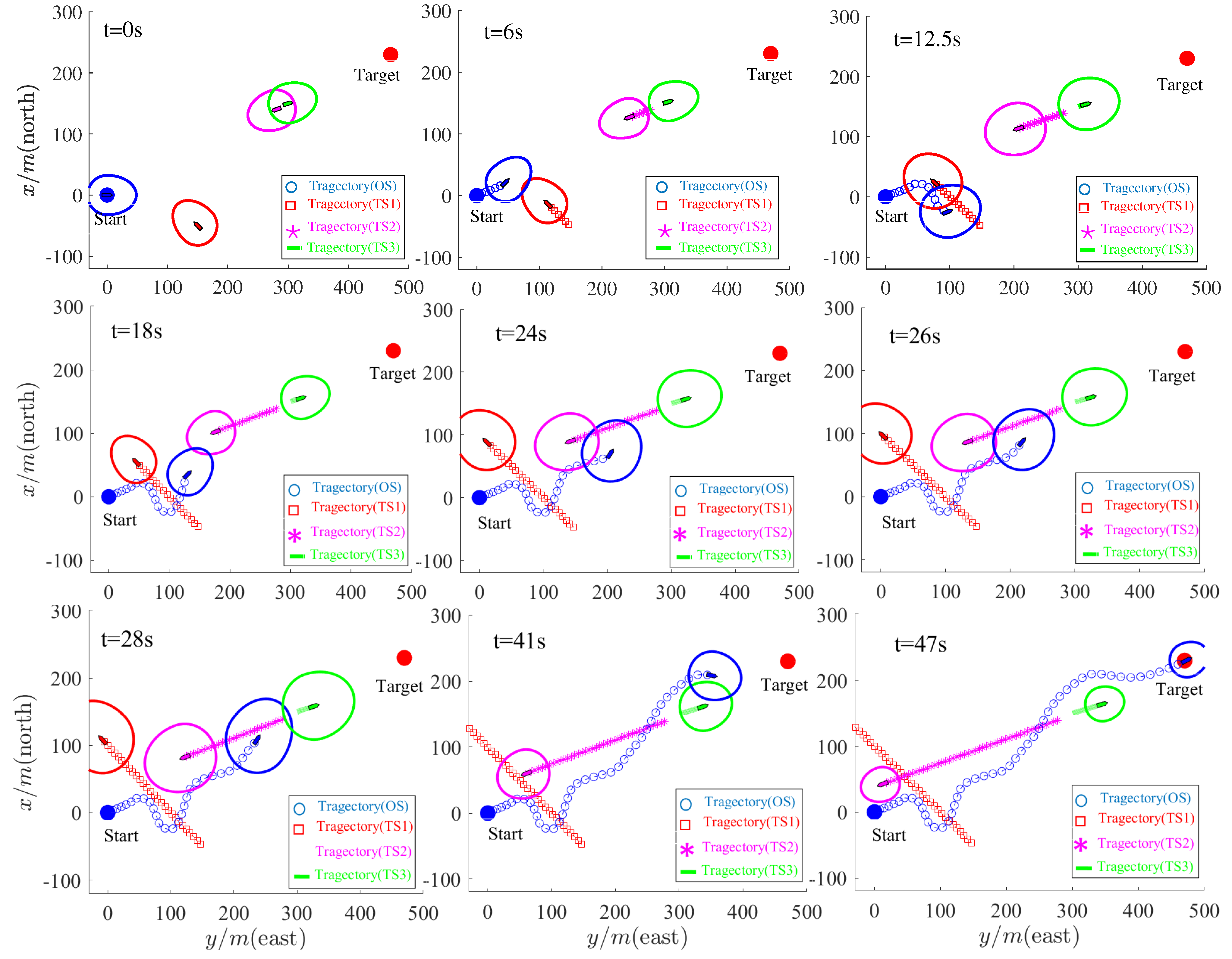
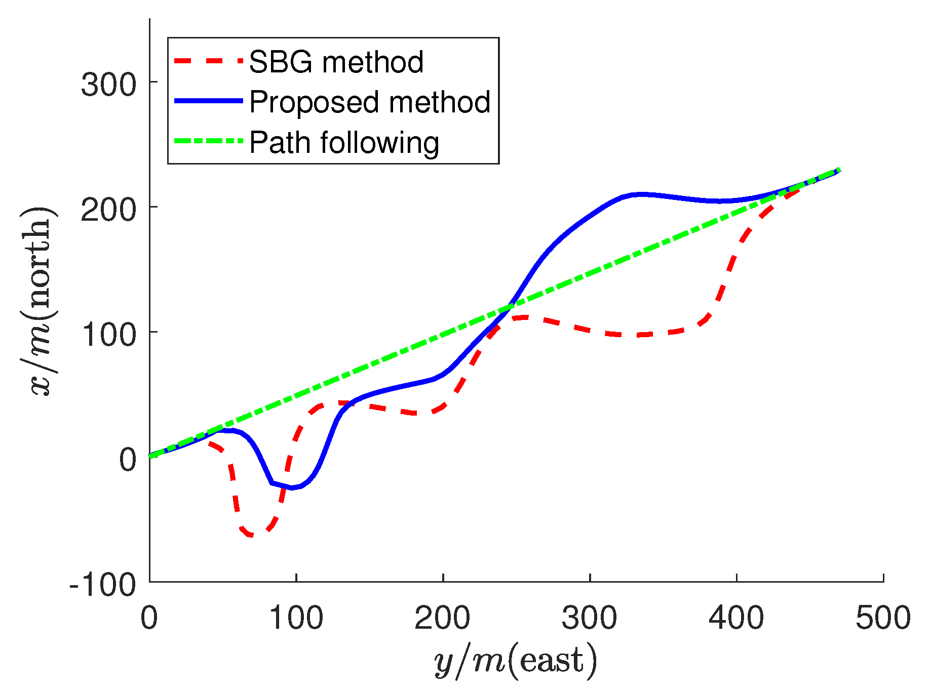
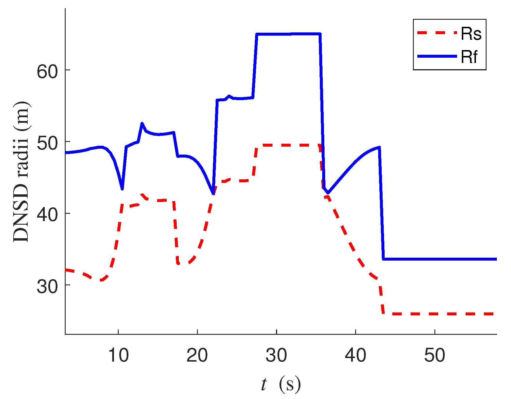
5.3. Multiple Obstacle Avoidance Performance Verification

Simulations were also implemented to verify the effectiveness and superiority for multiple obstacle avoidance. The simulation results are shown in Figure 13, where the blue boat and solid circle represent the OS and the ship domain of the OS, respectively; the red, purple, and green boat and solid circle represent the ship and the ship domain of TS1, TS2, and TS3, respectively. The blue dotted circle represents the starting point of the OS; the red dotted circle represents the end of the OS.
It can be seen that the OS firstly crossed from the port side of TS1. The OS began to make an avoidance maneuver at t = 7 s and passed through the port side of TS1. At t = 12.5 s, it successfully avoided TS1 and switched to path following mode. After that, the OS met on a reciprocal course with TS2 and began to make a head-on avoidance maneuver by altering its course to starboard at t = 18 s. At t = 24 s, it successfully avoided TS2. Finally, the OS came up to TS3 and began to make an overtaking avoidance maneuver at t = 28 s. The OS altered its course to port side and overtook TS3. At t = 41 s, it successfully avoided TS3 and reached the destination by path following at t = 47 s. The simulation result demonstrated the effectiveness of the DNSD-based algorithm for multiple obstacle avoidance. The changing curve of the OS ship domain is illustrated in Figure 14. We can see that the radii of the ship domain changed dramatically in accordance with the different encounter situations.
The comparison of the avoidance path trajectory using the SBG method and the proposed DNSD-based method is shown in Figure 15. The result indicates again that the length of the avoidance path under the proposed method was shorter than that under the SBG method, which validates the superiority of the proposed obstacle avoidance method for multiple dynamic obstacles.

6. Conclusions

This paper proposed a dynamic navigation ship domain-based (DNSD-based) dynamic obstacle avoidance algorithm for USVs in compliance with COLREGs. The DNSD-based method mainly consists of two steps: the obstacle avoidance risk inference and the local avoidance path planning. Firstly, the analytical DNSD model composed of a semi-ellipse and a semicircle was established. When the DNSDs of the own ship (OS) and the target ship (TS) intersect, the obstacle avoidance algorithm infers that there is a risk of collision and it is time to make avoidance maneuvers. Then, the local avoidance path planning algorithm redefines the local avoidance waypoints and replans the avoidance trajectory by ensuring that the OS does not violate the TS’s domain. The highlights here are that the DNSD was parameterized according to the ship parameters, maneuverability, sailing speed, and encounter situations regarding the relative bearing and COLREGs; thus, the avoidance response distance dynamic changes regarding different collision risks under different encounter situations and sailing speeds. Furthermore, in the proposed method, the DNSDs were taken as the general model contributing to navigation risk assessment and local avoidance path planning. Based on the DNSD, the algorithm can answer whether and when to make avoidance maneuvers and determine the avoidance path trajectory to take appropriate avoidance actions. Simulations were implemented for a single obstacle under different encounter situations (head-on, overtaking, and crossing) and multiple dynamic obstacles. The results demonstrated the effectiveness and superiority of the proposed DNSD-based obstacle avoidance algorithm.
In actual practice, a USV is always affected by external interference such as wind, waves, and current, which will cause the USV to deviate from its desired heading. Therefore, in the future research, it will be of great importance to develop the collision avoidance approach for a USV under external interference and suppress the influence of external interference.

Author Contributions

Conceptualization, F.D.; methodology, F.D.; software, L.J.; validation, F.D., L.J. and B.L.; investigation, X.H.; data curation, L.J.; writing—original draft preparation, L.J.; writing—review and editing, F.D.; visualization, L.J.; supervision, F.D. and L.W.; project administration, F.D.; funding acquisition, F.D. and H.Y. All authors have read and agreed to the published version of the manuscript.

Funding

This research is funded by the Natural Science Foundation of Shandong Province (Grant No. ZR2019MEE102) and the Collaborative Innovation Center of Intelligent Green Manufacturing Technology and Equipment, Shandong (Grant No. IGSD-2020-011)

Institutional Review Board Statement

Not applicable.

Informed Consent Statement

Not applicable.

Data Availability Statement

Not applicable.

Acknowledgments

The authors are thankful for the funding from the Natural Science Foundation of Shandong Province (Grant No. ZR2019MEE102) and the Collaborative Innovation Center of Intelligent Green Manufacturing Technology and Equipment, Shandong (Grant No. IGSD-2020-011).

Conflicts of Interest

The authors declare no conflict of interest.

References

  1. Kurowski, M.; Thal, J.; Damerius, R.; Korte, H.; Jeinsch, T. Automated Survey in Very Shallow Water Using an Unmanned Surface Vehicle. IFAC PapersOnLine 2019, 52, 146–151. [Google Scholar] [CrossRef]
  2. Specht, M.; Specht, C.; Mindykowski, J.; Dąbrowski, P.; Maśnicki, R.; Makar, A. Geospatial Modeling of the Tombolo Phenomenon in Sopot using Integrated Geodetic and Hydrographic Measurement Methods. Remote Sens. 2020, 12, 737. [Google Scholar] [CrossRef]
  3. Stateczny, A.; Burdziakowski, P.; Najdecka, K.; Domagalska-Stateczna, B. Accuracy of Trajectory Tracking Based on Nonlinear Guidance Logic for Hydrographic Unmanned Surface Vessels. Sensors 2020, 20, 832. [Google Scholar] [CrossRef] [PubMed]
  4. Campbell, S.; Naeem, W.; Irwin, G.W. A review on improving the autonomy of unmanned surface vehicles through intelligent collision avoidance manoeuvres. Annu. Rev. Control. 2012, 36, 267–283. [Google Scholar] [CrossRef]
  5. Fu, M.Y.; Wang, S.S.; Wang, Y.H. Multi-Behavior Fusion Based Potential Field Method for Path Planning of Unmanned Surface Vessel. China Ocean. Eng. 2019, 33, 583–592. [Google Scholar] [CrossRef]
  6. Mousazadeh, H.; Kiapey, A. Experimental Evaluation of A New Developed Algorithm for An Autonomous Surface Vehicle and Comparison with Simulink Results. China Ocean. Eng. 2019, 33, 268–278. [Google Scholar] [CrossRef]
  7. Gao, Z.J.; Zhang, Y.J.; Sun, P.T. Overview of research on unmanned ships. J. Dalian Marit. Univ. 2017, 43, 1–7. [Google Scholar]
  8. Woo, J.; Kim, N. Collision avoidance for an unmanned surface vehicle using deep reinforcement learning. Ocean. Eng. 2020, 199, 107001. [Google Scholar] [CrossRef]
  9. Baker, C.C.; Seah, A.K. Maritime accidents and human performance: The statistical trail. In Proceedings of the MARTECH 2004, Singapore, 22–24 September 2004. [Google Scholar]
  10. Huang, Y.M.; van Gelder, P.H.A.J.M. Collision risk measure for triggering evasive actions of maritime autonomous surface ships. Saf. Sci. 2020, 127, 104708. [Google Scholar] [CrossRef]
  11. Almeida, C.; Franco, T.; Ferreira, H.; Martins, A.; Santos, R.; Almeida, J.M.; Carvalho, J.; Silva, E. Radar based collision detection developments on usv ROAZ II. In Proceedings of the Oceans 2009-Europe, Bremen, Germany, 11–14 May 2009. [Google Scholar]
  12. Kuwata, Y.; Wolf, M.; Zarzhitsky, D.; Huntsberger, T. Safe maritime autonomous navigation with COLREGS, using velocity obstacles. IEEE J. Ocean. Eng. 2014, 39, 110–419. [Google Scholar] [CrossRef]
  13. Szlapczynski, R.; Szlapczynska, J. Review of ship safety domains: Models and applications. Ocean. Eng. 2017, 145, 277–289. [Google Scholar] [CrossRef]
  14. Fujii, Y.; Tanaka, K. Traffic Capacity. J. Navig. 1971, 24, 543–552. [Google Scholar] [CrossRef]
  15. Fiskin, R.; Nasiboglu, E.; Yardimci, M.O. A knowledge-based framework for two-dimensional (2D) asymmetrical polygonal ship domain. Ocean. Eng. 2020, 202, 107187. [Google Scholar] [CrossRef]
  16. Myre, H. Collision Avoidance for Autonomous Surface Vehicles Using Velocity Obstacle and Set-Based Guidance. Master’s Thesis, Norwegian University of Science and Technology, Norwegian, Trondheim, Norway, 2015. [Google Scholar]
  17. Coldwell, T. Marine traffic behavior in restricted waters. J. Navig. 1983, 36, 430–444. [Google Scholar] [CrossRef]
  18. Davis, P.; Dove, M.; Stockel, C. A computer simulation of marine traffic using domains and arenas. J. Navig. 1980, 33, 215–222. [Google Scholar] [CrossRef]
  19. Zhou, J.; Wang, C.; Zhang, A.A. COLREGs-based dynamic navigation safety domain for unmanned surface vehicles: A case study of Dolphin-I. J. Mar. Sci. Eng. 2020, 8, 264. [Google Scholar] [CrossRef]
  20. Wang, N. An intelligent spatial collision risk based on the quaternion ship domain. J. Navig. 2010, 63, 733–749. [Google Scholar] [CrossRef]
  21. Zheng, K.; Chen, Y.; Jiang, Y.; Qiao, S. A SVM based ship collision risk assessment algorithm. Ocean Eng. 2020, 202, 107062. [Google Scholar] [CrossRef]
  22. Patle, B.K.; Ganesh, B.L.; Pandey, A.; Parhi, D.R.K.; Jagadeesh, A. A review: On path planning strategies for navigation of mobile robot. Def. Technol. 2019, 15, 582–606. [Google Scholar] [CrossRef]
  23. Shi, J.H.; Liu, Z.J. Deep Learning in Unmanned Surface Vehicles Collision-Avoidance Pattern Based on AIS Big Data with Double GRU-RNN. J. Mar. Sci. Eng. 2020, 8, 682. [Google Scholar] [CrossRef]
  24. Zhang, Y.Y.; Qu, D.; Ke, J.; Li, X.M. Dynamic obstacle avoidance of unmanned surface vehicle based on speed obstacle method and dynamic window method. J. Shanghai Univ. 2017, 23, 1–16. [Google Scholar]
  25. Fiorini, P.; Shiller, Z. Motion Planning in Dynamic Environments Using Velocity Obstacles. Int. J. Robot. Res. 1998, 17, 760–772. [Google Scholar] [CrossRef]
  26. Kuwata, Y.; Wolf, M.T.; Zarzhitsky, D.; Huntsberger, T.L. Safe maritime navigation with COLREGs using velocity obstacles. In Proceedings of the IEEE/RSJ International Conference on Intelligent Robots and Systems, San Francisco, CA, USA, 3–8 November 2011. [Google Scholar]
  27. Larson, J.; Bruch, M.; Ebken, J. Autonomous navigation and obstacle avoidance for unmanned surface vehicles. In Proceedings of the SPIE 6230, Unmanned Systems Technology VIII, Orlando, FL, USA, 18–20 April 2006. [Google Scholar]
  28. Song, L.; Su, Y.; Dong, Z.; Shen, W.; Xiang, Z.; Mao, P. A two-level dynamic obstacle avoidance algorithm for unmanned surface vehicles. Ocean. Eng. 2018, 170, 351–360. [Google Scholar] [CrossRef]
  29. Moe, S.; Teel, A.R.; Antonelli, G.; Pettersen, K.Y. Experimental results for set-based control within the singularity-robust multiple task-priority invers kinematics. In Proceedings of the 2015 IEEE Conference on Robotics and Biomimetics, Zhuhai, China, 6–9 December 2015. [Google Scholar]
  30. Moe, S.; Teel, A.R.; Antonelli, G.; Pettersen, K.Y. Stability analysis for set-based control within the singularity-robust multiple task-priority inverse kinematics framework. In Proceedings of the 2015 IEEE 54th Annual Conference on Decision and Control (CDC), Osaka, Japan, 15–18 December 2015. [Google Scholar]
  31. Li, C.; Jiang, J.; Duan, F.; Liu, W.; Wang, X.; Bu, L.; Sun, Z.; Yang, G. Modeling and Experimental Testing of an Unmanned Surface Vehicle with Rudderless Double Thrusters. Sensors 2019, 19, 2051. [Google Scholar] [CrossRef]
  32. Fossen, T.I. Handbook of Marine Craft Hydrodynamics and Motion Control; John Wiley & Sons: Chichester, UK, 2011; pp. 52–59. [Google Scholar]
  33. Goodwin, E.M. A statistical study of ship domains. J. Navig. 1975, 28, 328–344. [Google Scholar] [CrossRef]
  34. Wang, N. A novel analytical framework for dynamic quaternion ship domains. J. Navig. 2013, 66, 265–281. [Google Scholar] [CrossRef]
  35. Kijima, K.; Furukawa, Y. Automatic collision avoidance system using the concept of blocking area. In Proceedings of the IFAC Manoeuvring and Control of Marine Craft, Girona, Spain, 17–19 September 2003. [Google Scholar]
  36. Mu, D.; Wang, G.; Fan, Y.; Qiu, B.; Sun, X. Adaptive Trajectory Tracking Control for Underactuated Unmanned Surface Vehicle Subject to Unknown Dynamics and Time-varing Disturbances. Appl. Sci. 2018, 8, 547. [Google Scholar] [CrossRef]
  37. Do, K.D.; Jiang, Z.P.; Pan, J. Universal controllers for stabilization and tracking of underactuated ships. Syst. Control. Lett. 2002, 47, 299–317. [Google Scholar] [CrossRef]
Figure 1. Different domain-based safety criteria [13]: (a) OS domain is not violated; (b) target ship (TS) domain is not violated; (c) neither of the ship domains should be violated; (d) ship domains should not overlap.
Jmse 09 00837 g001
Figure 2. Encounter situations and the avoidance direction for collision avoidance according to COLREGs (blue boat: OS, red boat: TS). (a) is overtaking situations; (b) is head-on situations; (c) is crossing situations.
Jmse 09 00837 g002
Figure 3. The boundaries between different COLREGs encounter situations (red boat: TS, blue boat: OS).
Jmse 09 00837 g003
Figure 4. The proposed dynamic navigation ship domain (DNSD).
Jmse 09 00837 g004
Figure 5. DNSD-based collision avoidance regarding COLREGs for different encounter situations: (a) overtaking; (b) head—on; (c) crossing.
Jmse 09 00837 g005
Figure 6. Determination of new way points and the local avoidance path planning process.
Jmse 09 00837 g006
Figure 7. Finish obstacle avoidance.
Jmse 09 00837 g007
Figure 8. Flowchart of DNSD-based dynamic obstacle avoidance.
Jmse 09 00837 g008
Figure 9. Block diagram of the dynamic obstacle avoidance system.
Jmse 09 00837 g009
Figure 10. Simulation results of a single TS representing different encounter situations in COLREGs: (a) crossing; (b) overtaking; (c) head−on.
Jmse 09 00837 g010
Figure 11. The changes of the ship domain dimensions for different encounter situations: (a) crossing; (b) overtaking; (c) head−on.
Jmse 09 00837 g011
Figure 12. Comparison of the avoidance path trajectory for different encounter situations (a) crossing; (b) overtaking; (c) head−on.
Jmse 09 00837 g012
Figure 13. Simulation results of multiple obstacle avoidance.
Jmse 09 00837 g013
Figure 14. The changes of the ship domain dimensions for multiple obstacle avoidance.
Jmse 09 00837 g014
Figure 15. Comparison of the avoidance path trajectory for multiple dynamic obstacle avoidance.
Jmse 09 00837 g015
Table 1. Viknes830 vessel parameters [16].
ParameterValueUnitParameterValueUnit
X u ˙ 0kg N r −3224kg·m 2 /s
Y v ˙ 0kg X u u −315kg/m 2
Y r ˙ 0kg·m Y v v −2000kg/s 2
N v ˙ 0kg·m N r r 0kg·m 2
N r ˙ 0kg·m 2 X u u u 0kg/(m·s)2
X u −50kg/s Y v v v 0kg/(m·s)2
Y v −200kg/s N r r r −3224kg/(m·s)2
Y r 0kg·m/sm3980kg
N v 0kg·m/s I z 19,703kg·m 2
Table 2. Motion parameters for the OS and TSs.
Simulation SceneVesselStarting PointDestinationVelocity (m/s)Heading (deg)
Signal TSOvertakingOS ( 0 , 0 ) ( 230 , 470 ) 150
TS ( 150 , 300 ) 273
Head-onOS ( 0 , 0 ) ( 160 , 320 ) 150
TS ( 140 , 280 ) 8250
CrossingOS ( 0 , 0 ) ( 130 , 285 ) 150
TS ( 50 , 150 ) 8315
Multiple TSsOS ( 0 , 0 ) ( 230 , 470 ) 150
TS1 ( 50 , 150 ) 8315
TS2 ( 130 , 280 ) 6250
TS3 ( 150 , 300 ) 273
Publisher’s Note: MDPI stays neutral with regard to jurisdictional claims in published maps and institutional affiliations.

