Article

Investigation on Hydrodynamic Performance of Flapping Foil Interacting with Oncoming Von Kármán Wake of a D-Section Cylinder

1
School of Marine Science and Technology, Northwestern Polytechnical University, Xi’an 710072, China
2
School of Aerospace Engineering, Tsinghua University, Beijing 100084, China
*
Authors to whom correspondence should be addressed.
J. Mar. Sci. Eng. 2021, 9(6), 658; https://doi.org/10.3390/jmse9060658
Submission received: 7 April 2021 / Revised: 9 June 2021 / Accepted: 11 June 2021 / Published: 14 June 2021
(This article belongs to the Section Ocean Engineering)

Abstract

:
Flapping foils are studied to achieve an efficient propeller. The performance of the flapping foil is influenced by many factors such as oncoming vortices, heaving amplitude, and geometrical parameters. In this paper, investigations are performed on flapping foils to assess its performance in the wake of a D-section cylinder located half a diameter in front of the foil. The effects of heaving amplitude and foil thickness are examined. The results indicate that oncoming vortices facilitate the flapping motion. Although the thrust increases with the increasing heaving amplitude, the propelling efficiency decreases with it. Moreover, increasing thickness results in higher efficiency. The highest propelling efficiency is achieved when the heaving amplitude equals ten percent of the chord length with a symmetric foil type of NACA0050 foil. When the heaving amplitude is small, the influence of the thickness tends to be more remarkable. The propelling efficiency exceeds 100% and the heaving amplitude is 10% of the chord length when the commonly used equation is adopted. This result demonstrates that the flapping motion extracts some energy from the oncoming vortices. Based on the numerical results, a new parameter, the energy transforming ratio (RET), is applied to explicate the energy transforming procedure. The RET represents that the flapping foil is driven by the engine or both the engines and the oncoming vortices with the range of RET being (0, Infini) and (−1, 0), respectively. With what has been discussed in this paper, the oncoming wake of the D-section cylinder benefits the flapping motion which indicates that the macro underwater vehicle performs better following a bluff body.

1. Introduction

By mimicking ocean creatures, researchers promote a myriad of new outstanding underwater vehicles. The flapping motion is believed to be an efficient self-propelling or energy extracting method. The fluid dynamics of flapping foils have been concentrated on for several decades, especially on its propulsion performance, with a focus on trying to find a pitching strategy for maximizing the thrust [1] and to explain the relationship between the geometry and the spanwise components of the locally shed vortices [2] or to find a semi-active flapping motion to improve the performance [3]. Factors that may produce effects on the hydrodynamic performance have been studied since early periods. It has been proven that a combined oscillating foil performs better than a pure heaving or a pure pitching foil in most conditions [4,5]. Moreover, the phase difference and pivot points do have a perfect value, which we applied here, for more efficient propulsion described in the work of Lin and Wu [6]. The Reynolds number, foil thickness, and camber were found to play a certain part by working on changing the leading-edge vortex [7]. These studies indicate that the formation and evolution of the leading-edge vortex(LEV) and trailing edge vortex(TEV) play a significant role in improving the performance. Thus, the performance of the flapping foil is connected with the factors that may affect the LEV and TEV [8,9,10].
It is known that the environment of the flowing water is always complex, which includes various vortices and fluctuations, and the shedding of LEV and TEV are consequently affected. Thus, hydrodynamic performance could be different. The interaction of the coming wake and the fixed foil was studied, with a focus concerning the vortex structure and force characteristics [11]. A series of numerical works for dual-foil turbines [12,13,14] or propulsion wing [15,16,17] are carried out. However, the relation between the oncoming vortices and the improvement of their performance is not clear. A two-dimensional inviscid analysis was carried out, which indicates that the phase between foil motion and the arrival of oncoming vortices is a critical parameter, and the highest efficiency is observed when the phase is such that the foil moves in close proximity with respect to the oncoming vortices [18]. The encounter between oncoming inverted von Kármán vortices and the free-pitching foil was studied by Bao [19], which indicated that the interaction is positive for thrust efficiency. An excellent investigation was performed to reveal the passive propulsion in vortex wake (a von Kármán wake) via an experiment method [20] and it was shown that there was a suction area in a cylinder wake that could drive the dead fish moving forward. Recently, the drag of a NACA0012 is found negative at two and three diameters downstream of the cylinder due to large regions of flow recirculation and the formation of an LEV, respectively [21]. It can be inferred that the oncoming wake can be positive for the flapping foil. However, most of the works mentioned above are about the foil flapping in the inverted von Kármán wake or a fixed foil in the von Kármán wake. The present work focuses mainly on the questions: Whether the oncoming vortices are positive with respect to the thrust generation for a foil oscillating near the D-section cylinder (a gap of half diameter of the cylinder); how does the motion parameters and foil geometry affect the hydrodynamic performance? How does the confluent wake change?
The present paper details a series of numerical simulations performed with various foil sections flapping in the wake of a D-section cylinder. The performance of the foil flapping in the open flow and the characteristic of the wake of the D-section cylinder are studied first. Then, the effects of the heaving amplitude and foil thickness are discussed. Finally, the energy transformation ratio is elaborated to explicate the energy transforming procedure, while, according to the results, the commonly used formula of propelling efficiency could not describe this interaction well when considering the oncoming wake.

2. Computational Approach

2.1. Problem Formulation

In this study, the two-dimensional flow fields of a flapping foil in the wake of a fixed D-section cylinder arranged tandemly are numerically studied. The flapping foil oscillates in the wake of the D-section cylinder and the leading edge vortex interacts with the oncoming wake. The shedding vortices of the D-section cylinder are disturbed by the foil and its LEV.
Based on previous research, the foil and the cylinder are the same scales, as shown in Figure 1a, where U0 is the velocity of the incoming flow and it is adopted as the characteristic velocity. D is the diameter of the cylinder and L is the distance between the D-section cylinder and the flapping foil. One of the main influences of the oncoming vortices on the flapping foil is when the vortices encounter the foil, which is believed that the different heaving amplitudes are quite outstanding when flapping in the wake. Thus, the parameter L is not discussed. Further work will be conducted on the length scale. Here, the length scale L is set as L = D/2 and the foil chord length is C where C = D. Amax is the amplitude of the heaving motion. The foil chord length is selected as the reference length. The Reynolds number can be defined as Re = U0C/υ. Here, υ represents the kinematic viscosity of the fluid. In this article, the Reynolds number is fixed as Re = 2 × 10⁴, which is identical to the number adopted in Young et al. simulation [7]. As for the coordinate system, the origin point is set behind the center of the cylinder for a length of L. The positive directions of the abscissa and ordinate axis are shown in Figure 1a.
Based on the reference length, the non-dimensional frequency can be defined with the following equation.
S r = f C U 0
The oscillating motion of the foil has been simplified by researchers from the behavior of marine organisms. One of the flapping modes discussed by DU [22], which is confirmed that it is a propeller motion when Re = 1100 as shown in Figure 1b, is applied here with a higher Re which may turn the motion into a drag one. The formula can be described as the following:
H e a v i n g : y ( t ) = A max sin ( 2 π f t ) P i t c h i n g : θ ( t ) = θ max sin ( 2 π f t + ϕ )
where f is the frequency and T = 1/f. ϕ is the phase difference between the heaving motion and pitching motion, which is fixed as ϕ = π/2 according to previous studies. Meanwhile, the amplitude of pitching motion θ max equals to π/12. The pitch center is fixed at the position of Or, as shown Figure 1b, which is C/3 from the leading edge on the chord.
With the known motion of flapping foils shown in Equation (2), the velocity and the angular velocity can be expressed as follows:
v ( t ) = 2 π f A max cos ( 2 π f t ) ω ( t ) = 2 π f θ max cos ( 2 π f t + ϕ )
where v ( t ) and ω ( t ) represent velocity and angular velocity, respectively. Symbols C T , C L and C M [23] are adapted to donate the instantaneous thrust coefficient, lift coefficient, and moment coefficient, respectively. The coefficients are as follows: C T = F x 0.5 ρ U 0 2 C S , C L = F y 0.5 ρ U 0 2 C S , C M = M 0.5 ρ U 0 2 C 2 S and Fx, Fy, M, and S stands for the thrust, lift, torque, and foil span, respectively.
In order to study the performance of flapping foils, the consuming power or the power of energy collecting is studied with the non-dimensional coefficients. Therefore, the time-mean thrust coefficient and the time-mean power coefficient are described as follows:
C T m e a n = 1 n T t 0 t 0 + n T C T d t C P m e a n = 1 n T t 0 t 0 + n T ( C L ( t ) v ( t ) + C M ω ( t ) S ) d t / U 0
where n = 3 represents the cycles used to calculate the time-mean coefficient.
The propulsive efficiency of the flapping foil is described as follows.
η T = C T m e a n C P m e a n

2.2. Numerical Method

The unsteady flow field around the cylinder and flapping foil, which is considered viscosity and incompressible, is simulated with an unsteady incompressible solver using the commercially available CFD code (ANSYS Fluent). Therefore, the continuity and momentum equations are described as follows:
ρ t + x i ( ρ u i ) = 0
( ρ u i ) t + x j ( ρ u i u j ) = p r x i + x j ( μ u i x j ρ u i u j ¯ ) + S i
where i, j = 1,2, ρ = constant, and ui uj are the transient velocity components, while u i and u j are the fluctuating velocity components. The component pr is the transient pressure and u i u j ¯ is the mean value of u i u j . The sum of all other force components that do not belong to the transient term is S i . Moreover, the subscripts i, j = 1,2 in Equations (6) and (7) identify the components along the X-axis and the Y-axis.
The finite-volume method is applied to achieve the spatial discretization of the Navier–Stokes equations (Equations (6) and (7)) and temporal discretization is performed using the second-order accuracy backward-implicit scheme. The k-ω SST turbulence model includes the transverse dissipative derivative term, which has been commonly tested and believed to be suitable for the turbulence and shear flow, used with wall restriction, which is employed here to solve the unsteady flow. The method is validated by Ashraf et al. [7] and the results agree very well with the published results shown in Figure 2, where k = Srπ/C.

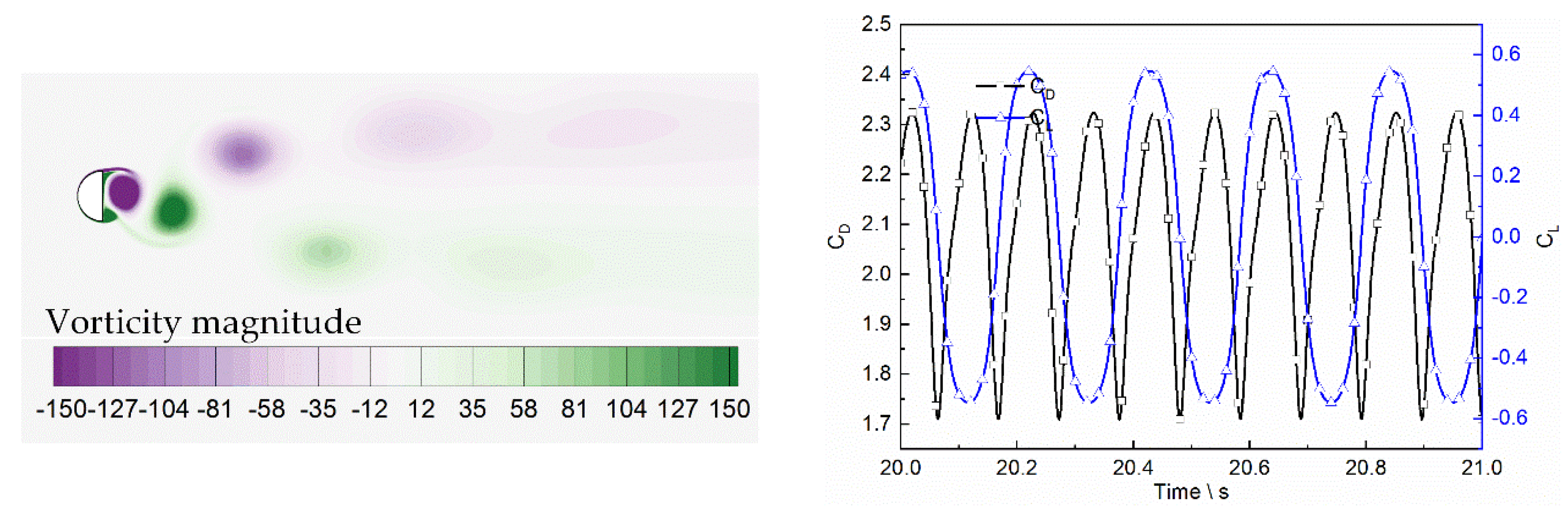
3. Validation of the Numerical Method

As described in the numerical study of Ashraf et al. [7], the turbulence model has been validated with quite an accuracy shown in Figure 2.
Six different mesh sizes (with different heights of the first cell layer [24] are tested. The inlet velocity is 0.292 m/s, the movement formula is the same with Equation (2), and the amplitude of the pitching motion is π/6. The results are listed in Table 1, where Δ = | C T m e a n ( i + 1 ) C T m e a n ( i ) C T m e a n ( i ) | × 100 % . The result converges and the result of case 5 is close enough to case 6, which suggests that the method and size of case 6 satisfies the calculation of the present numerical simulation.
In order to confirm the accuracy of this mesh method with the k-ω SST turbulence model, it is tested again to compare with the experiment and linear and nonlinear theory results [25]. Figure 3 provides the thrust coefficient and power coefficient as a function of Sr for the angle of attack at 15°, the amplitude of heaving motion Amax/C = 0.75, and with ϕ = π/2. The agreement between theory, experiment, and present simulation is fair overall.
The computational domain is considered as a square area in this study. The inlet velocity boundary is at a distance of 20C from the pitching center of the foil, as u = (U,0) and p x = 0 . As for the no-stress outflow boundary condition, u = (0,0) and p = 0 are used and the downstream pressure outlet is at a distance of 40C from the pitching center of the foil. The slip wall condition is used for the upper and lower flow boundaries located at a distance of 30C from the central line of the cylinder. With the chosen meshing strategy case 6, where y+ = 0.8, the first mesh layer could be estimated. The flow field is divided into three zones. The pitching foil is surrounded by structured grids (the orange color) and the up-down zone (gray color) and the fixed zone (blue and green color) are both constructed using a structured mesh, which is shown in Figure 4. Moreover, the DEFINE_CG_MOTION function and User Defined Function(UDF) [26] are used to handle the prescribed motion equations (Equation (2)) and regenerate the interface boundaries between the pitching zone and up-down zones. The formula presented by Kinsey and Dumas [27] is adopted to determine the time steps of the simulation and the formula is expressed as Δ t = min { T 2000 , C / v 100 } , where T is the oscillation period and ||v|| is the maximum instantaneous convective flux velocity in the computational domain.

4. Results and Discussion

In this section, numerical results are presented and discussed concerning the performance of hydrofoils with oscillatory motion in the wake of a D-section cylinder. The results of different foil thickness investigations are obtained as well as the tendencies of consuming power and thrust. Simulations are carried out with the fixed frequency and different heaving amplitudes. Hydrodynamic performance parameters and flow structures are studied.

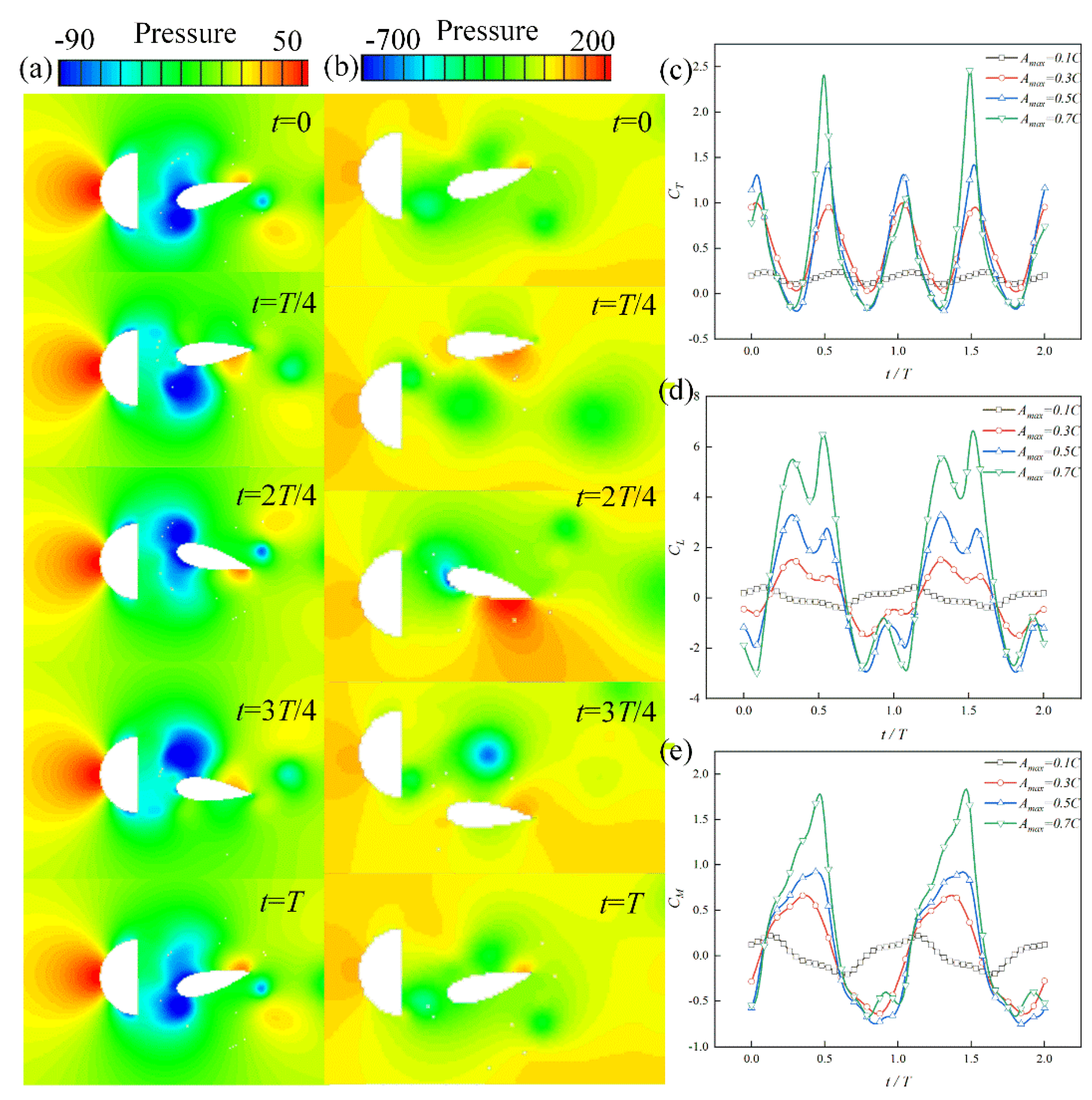
4.1. The Original Flapping Foil Motion and Flow Field of the D-Section Cylinder

The flapping foil is described as a propulsion device by DU at the condition that Re = 1100. However, we are concerned with the situation declared by M.A. Ashraf et al., where the Re = 2 × 10⁴. The non-dimensional frequency of the flapping foil is fixed at Sr = 0.3. The total flapping cycle and the vorticity magnitude are shown in Figure 5.
The vortices shedding from the leading edge pair up and the vortices shedding from the trailing edge form an inverted von Kármán wake (IVKW). According to Zhang’s conclusion, the thrust wake is most likely an IVKW, but an IVKW is not necessarily a thrust wake. This motion adapted by DU et al. is confirmed as a propelling motion with Re = 1100. However, when Re = 2 × 10⁴ is applied here, this motion provides no thrust. The instant thrust coefficient and time-mean thrust coefficient in two flapping periodic processes are shown in Figure 6.
According to Figure 5 and Figure 6, the thrust generated by the foil lasts a short period time and drag dominates the horizontal force. The process of the flapping foil for the second half of the flapping cycle is symmetric with the first four positions. It indicates the same horizontal force peak in the second half of the flapping cycle. This phenomenon supports the view that the growth and dissipation of the LEV and TEV play an important role in affecting the performance of the flapping foil. The time-mean thrust is negative, which means that this kind of motion does not provide thrust under the given Reynolds number.
The oncoming wake is typically a von Kármán wake (VKW) as shown in Figure 7a and the vortices shedding from D-section cylinder decay while proceeding downstream.
The instant drag coefficient and lift coefficient of the D-section cylinder are shown in Figure 7b. Both the curves exhibit very good periodicity and the period of the lift variation is twice of that with respect to the drag variation.
The Fast Fourier Transformation (FFT) is applied for the vortex shedding frequency as shown in Figure 8. The main frequency of the forces represents the vortices shedding frequency. The variation frequency of the lift coefficient equals exactly the frequency of vortices shedding due to the vortices of the D-section cylinder shedding at the top or bottom of the cylinder, which results in a pressure drop with respect to it. The frequency of the lift coefficient (marked as fL) is fL = 4.96 Hz, which indicates that the non-dimensional vortex shedding frequency of the D-section cylinder is Sr = f L D U 0 = 0.17.

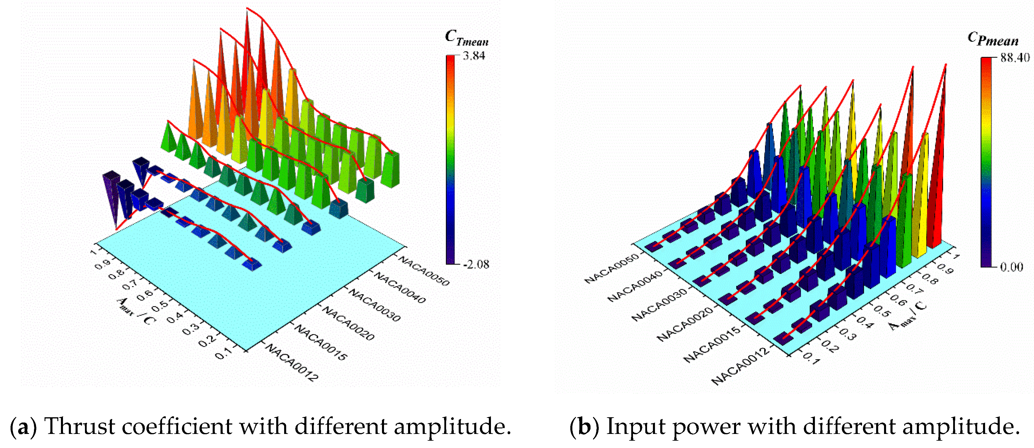
4.2. Effect of Heaving Amplitude and Thickness

The flapping foil is placed in the wake generated by the D-section cylinder, with a gap of 0.5D. The vortices shedding from the flapping foil will interfere with the on-coming VKW, which keeps growing. The interaction is mainly dependent on the heaving amplitude. Here, the flapping motion is limited with a flapping frequency of Sr = 0.3. The hydrodynamic performance of the flapping foil is described by the time-mean thrust coefficient and the energy-consuming power coefficient. The two parameters changing with respect to the heaving amplitude and foil thickness are shown in Figure 9 with 3D bar graphs.
The time-mean thrust increases significantly with the heaving amplitude for cases of NACA0030, NACA0040, and NACA0050 when Amax > 0.5C, while the NACA0020 cases remain stable. As for cases of NACA0012 and NACA0015, the thrust decreases and becomes negative, which means that the flapping foil produces drag and the drag increases with the heaving amplitude when Amax > 0.5C. The thrust coefficient remains steady when the amplitude is less than 0.5C. As for the effects of the foil thickness on the parameters, time-mean thrust increases with the thickness for all tested flapping frequencies, while the input power decreases. This indicates that the thicker foil performs better than the thinner foil, as shown in Figure 9.
With the definition of the propelling efficiency in Equation (5), the thrust time’s velocity is higher than the energy-consuming power, which results in the propelling efficiency exceeding 1, as shown in Figure 10. This ‘bizarre’ phenomenon is caused by the suction area behind the D-section cylinder. The results indicate that the moving forward motion requires less energy to maintain the moving velocity when the flapping propulsion device is involved in the suction area of a von Kármán wake with a small heaving amplitude. Moreover, it seems that the original equation used to calculate the propelling efficiency is not proper for the flapping motion when tracking a close target.
As shown in Figure 11, the vortex wake is a regular structure when the foil flaps in the wake with Amax < 0.5C. A pair of vortices are formed behind the foil during a flapping process. When the Amax > 0.5C, the vortex shedding from the foil will merge with the oncoming wake and will be disturbed by the foil. Consequently, a pair and one single vortex are formed, shown in Figure 11d. LEV is inhibited, which results in a low-pressure area in front of the foil and the thrust is enlarged when the amplitude increases.
The vortices shedding performance changes with the heaving amplitude, which results in the fluctuation of hydrodynamic parameters. The instantaneous CT, CL, and CM in two flapping cycles for NACA0030 with different heaving amplitudes are demonstrated in Figure 12. The fluctuation amplitudes of the three parameters increase with flapping amplitude, the highest peak of the thrust appears when the foil moves around the symmetric line at t = 0.5T during one cycle, while Amax > 0.5C.
As discussed above, when the foil flapping in the vortex street with heaving amplitude Amax < 0.5C, the vortex shedding is regular. The pressure distribution is symmetrical for the upwards and downwards processes, shown in Figure 12a, and so the peaks of the thrust coefficient are the same. While the heaving amplitude is larger than 0.5C, the confluent vortex wake could not remain as a pair. The pressure distribution is shown in Figure 12b, the highest pressure difference is observed when t = 0.5T, and the thrust coefficient reaches its peak as shown in Figure 12c. The pressure difference of the upper and lower surface reaches its peak when t is around 0.5T, which results in the peak of the lift coefficient. The center of the vortex becomes the center position of low pressure. Thus, the hydrodynamic performance of the flapping foil is closely related to the vortex shedding.
The thickness of the flapping foil plays an important role in improving the propelling force. The thrust of the thicker foil is higher than the thinner foil, as shown in Figure 9a. The vortex streets of different foils are shown in Figure 13.
The results indicate that the thickness of the foil affects the shedding of LEV. The shedding of LEV is delayed when the foil thickness grows. The oncoming clockwise vortex is pushed down and inhibits the anticlockwise vortex for the thinner foil as shown in Figure 13. When the foil is thicker than NACA0020, the distance between the anticlockwise vortex and the clockwise vortex is magnified. Moreover, it can be seen that the leading edge separation is evident and the diffusion of the resultant vortex decreases with the increasing thickness. Pressure around the vortices is lower than the flow field, thus the pressure at the leading edge remains low with a longer period time for the thicker foil, which results in a bigger time-mean thrust. The differential pressure resulting from delayed vortices benefits the pitching motion.

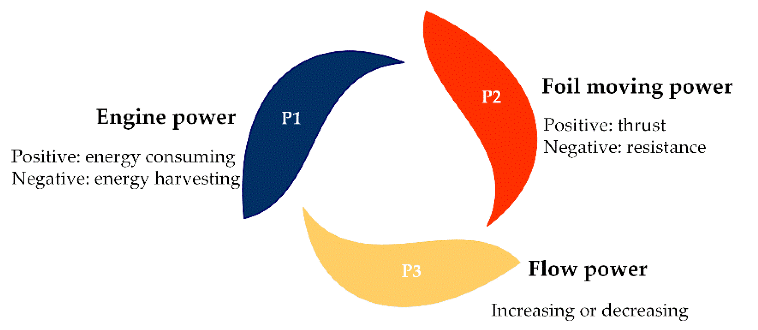
4.3. Definition of the Energy Transforming Ratio

The commonly used equation for the propelling efficiency is established by assuming that the flapping foil is driven by the engine to move forward in still water. However, the oncoming wake may enhance or depress the flapping motion. Thus, the propelling efficiency calculated by Equation (5) represents the ratio of the foil moving power and the engine power. In the present flapping system, there are three parts that should considered: (a) the engine power (P1), which donates energy consumption or harvesting by the flapping system; (b) the foil moving power(P2), which represents the propelling power of the flapping foil; (c) the flow energy(P3), which stands for the energy of the oncoming flow. The diagram of the energy system is shown in Figure 14.
According to the results discussed in the former parts, there are three types of energy transformations, as shown in Figure 15.
The modes are given as follows:
Mode 1: the flapping foil consumes energy from the oncoming wake and the engine, which works as a propulsion device.
Mode 2: the flapping foil extracts energy from the oncoming wake and the engine acts as a dynamo.
Mode 3: the engine provides power for the flapping foil to overcome resistance or to generate thrust and the upstream flow is accelerated.
Since we always focus on whether the foil could work as a propulsion device or as an energy harvester, the engine power (P1) and foil moving power (P2) are applied to calculate the newly defined energy transforming ratio as follows.
R E T = sign ( P 1 ) P 1 P 2 P 1 = P 1 P 2 | P 1 |
A negative value stands for the energy extraction from the oncoming wake by the foil and a positive value reflects that the engine’s power is driving the flapping foil.
If 1 > RET > 0, it means that part of the engine’s energy is applied for the foil working as a propulsion device and part of it is applied to accelerate the oncoming flow as shown in mode 3.
If RET ≥ 1, the flapping foil provides no thrust and it is considered that the flapping foil is working as a pump, as shown in mode 3.
If −1 < RET ≤ 0, the flapping foil extracts energy from the oncoming wake and the engine and is working as a propulsion device, as shown in mode 1.
If RET ≤ −1, this system could work as an energy harvester, as shown in mode 2.
When applied to Equation (8), the tendency of the energy transformation that varies with thickness is shown in Figure 16. The four conditions of the results described above are padded with different colors. The bright green color reflects that the flapping foil in the oncoming wake works as an energy harvester. Dark green means that the flapping propulsion device extracts energy from the oncoming wake and the energy provided by the engine. The orange stands for a common propeller driven by the engine. The red color indicates that the flapping foil performs negatively under these conditions.

5. Conclusions

The effects of heaving amplitude and foil thickness on the thrust and energy-consuming are numerically studied. The motion can be energized in the wake. The original drag-generating flapping motion provides thrust.
The heaving amplitude study is carried out at a range of 0.1C~1.0C on 2D NACA symmetric foils with a fixed frequency. The results indicate that the increasing amplitude results in a higher energy-consuming power and horizontal force. Moreover, when oscillation is enclosed in the wake (Amax < 0.5C), the horizontal force is quite steady and the confluent wake remained a von Kármán type. When the oscillation oversteps, the horizontal force and energy-consuming power witnesses significant growth. The confluent wake would change from VKW to IVKW and 1P+1S wake.
The thickness investigation was performed on the NACA symmetric foils with 12%, 15%, 20%, 30%, 40%, and 50% thick sections. The thrust increases with the thickness. The horizontal force tends to be a drag with a relatively thin foil. However, when the foil is thicker than NACA0020, it turns out to be thrust. The energy-consuming power decreases with growing thickness, which results in a higher propelling efficiency. The growing thickness delays the shedding of the LEV.
A newly defined parameter, energy transforming ratio (RET), is elaborated to solve the problem of the improper use of common propelling efficiency, according to the results discussed. This new parameter can describe the propelling efficiency and energy harvesting efficiency with its value located in different ranges.
Finally, when the micro underwater vehicles propelled by the flapping foil chases a bluff body, a small heaving amplitude and a thick section foil are preferred to construct the flapping propulsion device.

Author Contributions

Conceptualization, J.L. and P.W.; Methodology, D.L. and J.L.; Software: P.W.; Validation, X.A. and R.H.; Formal Analysis, J.L., D.L. and B.Z.; Investigation, J.L. and D.L.; Resources, P.W.; Data curation, J.L.; Writing—original draft preparation, J.L. and X.A.; Writing—review and editing, J.L., X.A., R.H., D.L. and B.Z.; Visualization, J.L. and B.Z.; Supervision, P.W.; Project administration, J.L.; Funding acquisition, P.W. All authors have read and agreed to the published version of the manuscript.

Funding

This work is supported by grants from the National Natural Science Foundation of China (Grant NO.51875466), (Grant NO.51805436), the Tsinghua University Shuimu Scholar Program (2020SM027), and the China Postdoctoral Science Foundation (BX20200187).

Conflicts of Interest

The authors declare no conflict of interest.

References

  1. Bockmann, E.; Steen, S. Experiments with actively pitch-controlled and spring-loaded oscillating foils. Appl. Ocean. Res. 2014, 48, 227–235. [Google Scholar] [CrossRef]
  2. Cheng, H.K.; Murillo, L.E. Lunate-tail swimming propulsion as a problem of curved lifting line in unsteady flow. 1: Asymptotic theory. J. Fluid Mech. 1984, 143, 327–350. [Google Scholar] [CrossRef]
  3. Thaweewat, N.; Phoemsapthawee, S.; Juntasaro, V. Semi-active flapping foil for marine propulsion. Ocean. Eng. 2018, 147, 556–564. [Google Scholar] [CrossRef]
  4. Liu, P.; Liu, Y.; Huang, S.; Zhao, J.; Su, Y. Effects of regular waves on propulsion performance of flexible flapping foil. Appl. Sci. 2018, 8, 934. [Google Scholar] [CrossRef] [Green Version]
  5. Politis, G.K.; Tsarsitalidis, V.T. Flapping wing propulsor design: An approach based on systematic 3D-BEM simulations. Ocean. Eng. 2014, 84, 98–123. [Google Scholar] [CrossRef]
  6. Lin, X.; Wu, J.; Zhang, T.; Yang, L. Phase difference effect on collective locomotion of two tandem autopropelled flapping foils. Phys. Rev. 2019, 4, 54–101. [Google Scholar] [CrossRef]
  7. Ashraf, M.A.; Young, J.; Lai, J.C.S. Reynolds number, thickness and camber effects on flapping airfoil propulsion. J. Fluids Struct. 2011, 27, 145–160. [Google Scholar] [CrossRef]
  8. Andersen, A.; Bohr, T.; Schnipper, T.; Walther, J.H. Wake structure and thrust generation of a flapping foil in two-dimensional flow. J. Fluid Mech. 2017, 812, R4. [Google Scholar] [CrossRef] [Green Version]
  9. Das, A.; Shukla, R.K.; Govardhan, R.N. Existence of a sharp transition in the peak propulsive efficiency of a low-Re pitching foil. J. Fluid Mech. 2016, 800, 307–326. [Google Scholar] [CrossRef]
  10. Zhang, J. Footprints of a flapping wing. J. Fluid Mech. 2017, 818, 1–4. [Google Scholar] [CrossRef] [Green Version]
  11. Liao, Q.; Dong, G.J.; Lu, X.Y. Vortex formation and force characteristics of a foil in the wake of a circular cylinder. J. Fluids Struct. 2004, 19, 491–510. [Google Scholar] [CrossRef]
  12. Chen, Y.; Nan, J.; Wu, J. Wake effect on a semi-active flapping foil based energy harvester by a rotating foil. Comput. Fluids 2018, 160, 51–63. [Google Scholar] [CrossRef]
  13. Liu, W. A case study on tandem configured oscillating foils in shallow water. Ocean. Eng. 2017, 144, 351–361. [Google Scholar] [CrossRef] [Green Version]
  14. Ma, P.; Wang, Y.; Xie, Y.; Huo, Z. Numerical analysis of a tidal current generator with dual flapping wings. Energy 2018, 155, 1077–1089. [Google Scholar] [CrossRef]
  15. Alaminos-Quesada, J.; Fernandez-Feria, R. Aerodynamics of heaving and pitching foils in tandem from linear potential theory. AIAA J. 2020, 58, 27–42. [Google Scholar] [CrossRef]
  16. Arranz, G.; Flores, O.; Garcia-Villalba, M. Three-dimensional effects on the aerodynamic performance of flapping wings in tandem configuration. J. Fluids Struct. 2020, 94, 102893. [Google Scholar] [CrossRef]
  17. Muscutt, L.E.; Weymouth, G.D.; Ganapathisubramani, B. Performance augmentation mechanism of in-line tandem flapping foils. J. Fluid Mech. 2017, 827, 484–505. [Google Scholar] [CrossRef] [Green Version]
  18. Streitlien, K.; Triantafyllou, G.S.; Triantafyllou, M.S. Efficient foil propulsion through vortex control. AIAA J. 1996, 34, 2315–2319. [Google Scholar] [CrossRef]
  19. Bao, Y.; Tao, J. Dynamic reactions of a free-pitching foil to the reverse Karman vortices. Phys. Fluids 2014, 26, 031704. [Google Scholar] [CrossRef]
  20. Beal, D.N.; Hover, F.S.; Triantafyllou, M.S.; Liao, J.C.; Lauder, G.V. Passive propulsion in vortex wakes. J. Fluid Mech. 2006, 549, 385–402. [Google Scholar] [CrossRef] [Green Version]
  21. Lefebvre, J.N.; Jones, A.R. Experimental investigation of airfoil performance in the wake of a circular cylinder. AIAA J. 2019, 57, 2808–2818. [Google Scholar] [CrossRef]
  22. Du, X.X.; Zhang, Z.D. Numerical analysis of influence of four flapping modes on propulsion performance of underwater flapping foils. Eng. Mech. 2018, 35, 249–256. [Google Scholar]
  23. Lu, K.; Xie, Y.H.; Zhang, D. Numerical study of large amplitude, nonsinusoidal motion and camber effects on pitching airfoil propulsion. J. Fluids Struct. 2013, 36, 184–194. [Google Scholar] [CrossRef]
  24. Wang, J.; Liu, P.; Chin, C.; He, G. Numerical investigation of auto-pitch wing-in-ground effect oscillating foil propulsor. Appl. Ocean. Res. 2019, 89, 71–84. [Google Scholar] [CrossRef]
  25. Anderson, J.M.; Streitlien, K.; Barrett, D.S.; Triantafyllou, M.S. Oscillating foils of high propulsive efficiency. J. Fluid Mech. 1998, 360, 41–72. [Google Scholar] [CrossRef] [Green Version]
  26. Chao, L.-M.; Pan, G.; Zhang, D.; Yan, G.-X. Numerical investigations on the force generation and wake structures of a nonsinusoidal pitching foil. J. Fluids Struct. 2019, 85, 27–39. [Google Scholar] [CrossRef]
  27. Kinsey, T.; Dumas, G. Parametric study of an oscillating airfoil in a power-extraction regime. AIAA J. 2008, 46, 1318–1330. [Google Scholar] [CrossRef]
Figure 1. Diagrammatic sketch for the flapping foil.
Jmse 09 00658 g001
Figure 2. Variation of C Tmean against k for a plunging NACA0012 airfoil h = 0.4C, Re = 3 × 10⁶, adapted from (Ashraf, et al. 2011), Copyright © 2010 Elsevier Ltd.
Jmse 09 00658 g002
Figure 3. Validation of grid strategy, compared with linear, nonlinear, and experiment results.
Jmse 09 00658 g003
Figure 4. Computational domain and mesh details.
Jmse 09 00658 g004
Figure 5. Vorticity magnitude for a total flapping cycle of NACA0012 when Sr = 0.3 and Re = 2 × 10⁴.
Jmse 09 00658 g005
Figure 6. Instant thrust coefficient and time-mean thrust coefficient in two flapping cycles.
Jmse 09 00658 g006
Figure 7. Wake of the D-section cylinder and the drag and lift coefficients.
Jmse 09 00658 g007
Figure 8. Frequency spectrum of the drag coefficient and lift coefficient.
Jmse 09 00658 g008
Figure 9. Time-mean thrust coefficient and energy-consuming power coefficient with various heaving amplitude and thickness with Sr = 0.3, Re = 2 × 10⁴.
Jmse 09 00658 g009
Figure 10. Propelling efficiency changing with Amax with Sr = 0.3 and Re = 2 × 10⁴.
Jmse 09 00658 g010
Figure 11. Vorticity magnitude contours and vortex interactions at various Amax, with Sr = 0.3 and Re = 2 × 10⁴.
Jmse 09 00658 g011
Figure 12. Pressure distribution during one flapping cycle for (a) Amax = 0.2C and (b) Amax = 0.7C; (c) CT, (d) CL, and (e) CM in two flapping cycles stands for NACA0030 with different heaving amplitudes under the condition that Sr = 0.3 and Re = 2 × 10⁴.
Jmse 09 00658 g012
Figure 13. Vorticity magnitude contours and vortex interaction at various thicknesses with Sr = 0.3, Amax = 0.2C, and Re = 2 × 10⁴ at t/T = 1.
Jmse 09 00658 g013
Figure 14. Diagram of the energy system.
Jmse 09 00658 g014
Figure 15. Diagram of three types of energy transformations.
Jmse 09 00658 g015
Figure 16. Energy transforming ratio varying with thickness.
Jmse 09 00658 g016
Table 1. Mesh validation for different sizes.
Number123456
Y+5210.90.850.8
Size150,000230,000270,000360,000380,000410,000
C Tmean 52.020752.588552.989853.022953.016553.0163
Δ 1.09%0.76%0.06%0.01%0.00004%
Publisher’s Note: MDPI stays neutral with regard to jurisdictional claims in published maps and institutional affiliations.

