
Effects of Second-Order Hydrodynamics on the Dynamic Responses and Fatigue Damage of a 15 MW Floating Offshore Wind Turbine

Abstract
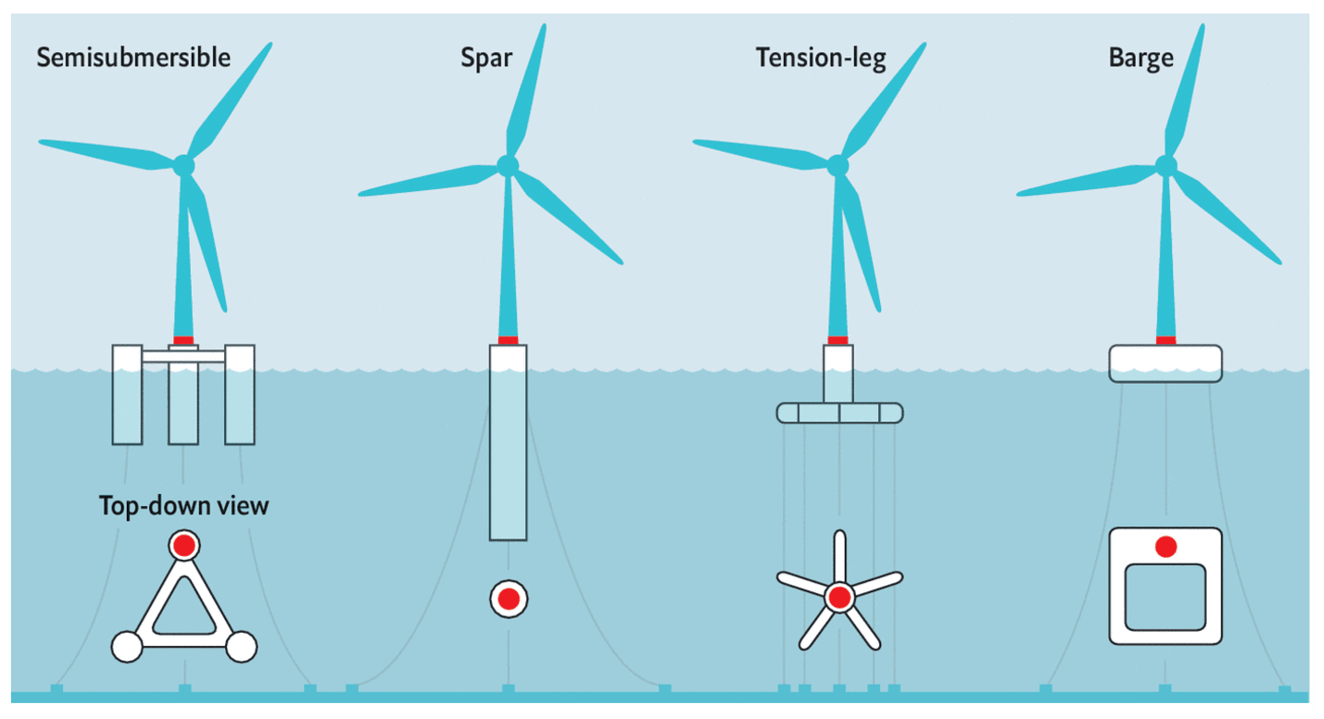
:1. Introduction
2. Model Description
2.1. The IEA 15 MW Wind Turbine
2.2. The ActiveFloat Platform
3. Fully Coupled Analysis Methodology
3.1. Description of the Aero-Servo-Elastic Modeling in F2A
3.2. Hydrodynamics in AQWA
4. Fatigue Evaluation Method Based on S-N Curves
5. Design Load Cases
6. Results and Discussions
6.1. Wave Excitations of the Platform
6.2. Dynamic Responses of the FOWT
6.2.1. Platform Motions
6.2.2. Tower-Base Loads
6.3. Fatigue Damage of the Tower
7. Conclusions
- (1)
- The sum- and difference-frequency QTFs of the 15 MW floating wind platform are calculated for a wide-range of wave frequency. The maximum surge QTF item is around 1% of the first-order wave excitation force. The sum-frequency QTF items with large magnitude are distributed in large frequency ranges.
- (2)
- The second-order hydrodynamics increase the maximum surge motions, since the surge mode is activated. The heave and pitch motions that are dominated by aerodynamic loads are slightly affected by the second-order excitations under power production cases. However, the extreme pitch and heave responses are enhanced due to the presence of second-order hydrodynamics. The maximum yaw motion is increased by 39% as well.
- (3)
- The tower-base bending moments are considerably affected by the second-order hydrodynamics. Both of the in-plane and out-of-plane bending moments are decreased if neglecting the contribution of second-order hydrodynamic loads. Nonetheless, the first-order wave excitation is the major contributor to the tower-base bending moments.
- (4)
- The fatigue damage rate at the 90 degree assessment point under the extreme condition is around 100 times larger than that in other load cases. The fatigue damage of the tower-base under the extreme condition is underestimated by 57.1% if the effect of second-order hydrodynamics is ignored.
- (5)
- The accumulative damage of each assessment point at the tower-base is lower than 1.0, implying that the structural design has satisfied the basic requirement of fatigue. In addition, the fatigue damage is overestimated by around 16.92% without the contribution of second-order wave excitations. Therefore, the second-order hydrodynamics must be considered in the design of tower of a FOWT to reduce the cost.
Author Contributions
Funding
Institutional Review Board Statement
Informed Consent Statement
Data Availability Statement
Acknowledgments
Conflicts of Interest
References
- Global Wind Energy Council. Global Wind Report 2020; GWEC: Brussel, Belgium, 2021. [Google Scholar]
- Det Norske Veritas and Germanischer Lloyd. The Energy Transition Outlook 2050; DNV-GL: Oslo, Norway, 2020. [Google Scholar]
- Jiang, Z. Installation of offshore wind turbines: A technical review. Renew. Sust. Energ. Rev. 2021, 139, 110576. [Google Scholar] [CrossRef]
- Robertson, A.; Jonkman, J.; Masciola, M.; Song, H.; Goupee, A.; Coulling, A.; Luan, C. Definition of the Semisubmersible Floating System for Phase II of OC4; National Renewable Energy Laboratory: Golden, CO, USA, 2014. [Google Scholar]
- Robertson, A.N.; Jonkman, J.M.; Goupee, A.J.; Coulling, A.J.; Prowell, I.; Browning, J.; Masciola, M.D.; Molta, P. Summary of conclusions and recommendations drawn from the DeepCwind scaled floating offshore wind system test campaign. In Proceedings of the International Conference on Offshore Mechanics and Arctic Engineering, Nantes, France, 9–14 June 2013. [Google Scholar]
- Masciola, M.; Robertson, A.; Jonkman, J.; Coulling, A.; Goupee, A. Assessment of the importance of mooring dynamics on the global response of the DeepCwind floating semisubmersible offshore wind turbine. In Proceedings of the International Offshore and Polar Engineering Conference, Anchorage, AK, USA, 30 June–5 July 2013. [Google Scholar]
- Hall, M.; Goupee, A. Validation of a lumped-mass mooring line model with DeepCwind semisubmersible model test data. Ocean Eng. 2015, 104, 590–603. [Google Scholar] [CrossRef] [Green Version]
- Coulling, A.J.; Goupee, A.J.; Robertson, A.N.; Jonkman, J.M.; Dagher, H.J. Validation of a FAST semi-submersible floating wind turbine numerical model with DeepCwind test data. J. Renew. Sustain. Energy 2013, 5, 023116. [Google Scholar] [CrossRef]
- Tran, T.T.; Kim, D.H. The coupled dynamic response computation for a semi-submersible platform of floating offshore wind turbine. J. Wind Eng. Ind. Aerodyn. 2015, 147, 104–119. [Google Scholar] [CrossRef]
- Kim, H.C.; Kim, M.H. Comparison of simulated platform dynamics in steady/dynamic winds and irregular waves for OC4 semi-submersible 5MW wind-turbine against DeepCwind model-test results. Ocean Syst. Eng. 2016, 6, 1–21. [Google Scholar] [CrossRef]
- Huang, Y.; Zhuang, Y.; Wan, D. Hydrodynamic Study and Performance Analysis of the OC4-DeepCWind Platform by CFD Method. Int. J. Comput. Methods 2021, 18, 2050020. [Google Scholar] [CrossRef]
- Liu, Z.; Fan, Y.; Wang, W.; Qian, G. Numerical study of a proposed semi-submersible floating platform with different numbers of offset columns based on the DeepCwind prototype for improving the wave-resistance ability. Appl. Sci. 2019, 9, 1255. [Google Scholar] [CrossRef] [Green Version]
- Lee, D.C.; Na, S.K.; Kim, S.; Kim, C.W. Deterministic fatigue damage evaluation of semi-submersible platform for wind turbines using hydrodynamic-structure interaction analysis. Int. J. Precis. Eng. 2021, 16, 1–12. [Google Scholar]
- Netzband, S.; Schulz, C.W.; Göttsche, U.; Ferreira, G.D.; Abdel, M.M. A panel method for floating offshore wind turbine simulations with fully integrated aero-and hydrodynamic modelling in time domain. Ship Technol. Res. 2018, 65, 123–136. [Google Scholar] [CrossRef]
- Ishihara, T.; Zhang, S. Prediction of dynamic response of semi-submersible floating offshore wind turbine using augmented Morison’s equation with frequency dependent hydrodynamic coefficients. Renew. Energy 2019, 131, 1186–1207. [Google Scholar] [CrossRef]
- Bayati, I.; Jonkman, J.; Robertson, A.; Platt, A. The effects of second-order hydrodynamics on a semisubmersible floating offshore wind turbine. J. Phys. Conf. Ser. 2014, 524, 012094. [Google Scholar] [CrossRef] [Green Version]
- Roald, L.; Jonkman, J.; Robertson, A.; Chokani, N. The effect of second-order hydrodynamics on floating offshore wind turbines. Energy Procedia 2013, 35, 253–264. [Google Scholar] [CrossRef] [Green Version]
- Zhou, S.; Müller, K.; Li, C.; Xiao, Y.; Cheng, P.W. Global sensitivity study on the semisubmersible substructure of a floating wind turbine: Manufacturing cost, structural properties and hydrodynamics. Ocean Eng. 2021, 221, 108585. [Google Scholar] [CrossRef]
- Pegalajar, J.A.; Bredmose, H. Reproduction of slow-drift motions of a floating wind turbine using second-order hydrodynamics and Operational Modal Analysis. Mar. Struct. 2019, 66, 178–196. [Google Scholar] [CrossRef]
- Zhang, L.; Shi, W.; Karimirad, M.; Michailides, C.; Jiang, Z. Second-order hydrodynamic effects on the response of three semisubmersible floating offshore wind turbines. Ocean Eng. 2020, 207, 107371. [Google Scholar] [CrossRef]
- Xu, K.; Gao, Z.; Moan, T. Effect of hydrodynamic load modelling on the response of floating wind turbines and its mooring system in small water depths. J. Phys. Conf. Ser. 2018, 1104, 012006. [Google Scholar] [CrossRef] [Green Version]
- Zhao, Z.; Wang, W.; Shi, W.; Li, X. Effects of second-order hydrodynamics on an ultra-large semi-submersible floating offshore wind turbine. Structures 2020, 28, 2260–2275. [Google Scholar] [CrossRef]
- Chuang, Z.; Liu, S.; Lu, Y. Influence of second order wave excitation loads on coupled response of an offshore floating wind turbine. Int. J. Nav. Archit. Ocean Eng. 2020, 12, 367–375. [Google Scholar] [CrossRef]
- Simos, A.N.; Ruggeri, F.; Watai, R.A.; Souto-Iglesias, A.; Lopez, P.C. Slow-drift of a floating wind turbine: An assessment of frequency-domain methods based on model tests. Renew. Energy 2018, 116, 133–154. [Google Scholar] [CrossRef]
- Cao, Q.; Xiao, L.; Guo, X.; Liu, M. Second-order responses of a conceptual semi-submersible 10 MW wind turbine using full quadratic transfer functions. Renew. Energy 2020, 153, 653–668. [Google Scholar] [CrossRef]
- Li, J.; Jiang, Y.; Tang, Y.; Qu, X.; Zhai, J. Effects of second-order difference-frequency wave forces on floating wind turbine under survival condition. Trans. Tianjin Univ. 2017, 23, 130–137. [Google Scholar] [CrossRef]
- Yang, Y.; Bashir, M.; Michailides, C.; Li, C.; Wang, J. Development and application of an aero-hydro-servo-elastic coupling framework for analysis of floating offshore wind turbines. Renew. Energy 2020, 161, 606–625. [Google Scholar] [CrossRef]
- Yang, Y.; Bashir, M.; Wang, J.; Michailides, C.; Loughney, S.; Armin, M.; Li, C. Wind-wave coupling effects on the fatigue damage of tendons for a 10 MW multi-body floating wind turbine. Ocean Eng. 2020, 217, 107909. [Google Scholar] [CrossRef]
- Yang, Y.; Bashir, M.; Wang, J.; Yu, J.; Li, C. Performance evaluation of an integrated floating energy system based on coupled analysis. Energy Convers. Manage. 2020, 223, 113308. [Google Scholar] [CrossRef]
- Li, D.; Lu, W.; Li, X.; Guo, X.X.; Li, J.; Duan, W.Y. Second-order resonant motions of a deep-draft semi-submersible under extreme irregular wave excitation. Ocean. Eng. 2020, 209, 107496. [Google Scholar] [CrossRef]
- Pham, T.D.; Shin, H. The Effect of the second-order wave loads on drift motion of a semi-submersible floating offshore wind turbine. J. Mar. Sci. Eng. 2020, 8, 859. [Google Scholar] [CrossRef]
- Pinkster, J.A. Mean and low frequency wave drifting forces on floating structures. Ocean. Eng. 1979, 6, 593–615. [Google Scholar] [CrossRef]
- Newman, J.N.; Lee, C.H. Boundary-element methods in offshore structure analysis. J. Offshore Mech. Arct. Eng. 2002, 124, 81–89. [Google Scholar] [CrossRef]
- Det Norske Veritas. DNV-RP-C203: Fatigue Design of Offshore Steel Structures; DNV: Oslo, Norway, 2013. [Google Scholar]
- Stewart, G.M.; Robertson, A.; Jonkman, J.; Lackner, M.A. The creation of a comprehensive metocean data set for offshore wind turbine simulations. Wind. Energy 2016, 19, 1151–1159. [Google Scholar] [CrossRef]


| Parameters/Unit | Value | Parameters/Unit | Value |
|---|---|---|---|
| Rated power/(MW) | 15 | Rotor diameter (m) | 240 |
| Turbine class/(-) | IEC Class 1B | Hub diameter (m) | 7.94 |
| Cut-in wind speed (m/s) | 3 | Hub overhang (m) | 11.35 |
| Cut-out wind speed (m/s) | 25 | Shaft tilt angle (deg) | 6 |
| Rated wind speed (m/s) | 10.59 | Rotor precone (deg) | −4 |
| Minimum rotor speed (rpm) | 5.0 | Blade prebend (m) | 4 |
| Maximum rotor speed (rpm) | 7.56 | Blade mass (kg) | 65,000 |
| Maximum tip speed (m/s) | 95 | Rotor-nacelle mass (kg) | 1,017,000 |
| Parameters/Unit | Value | Parameters/Unit | Value |
|---|---|---|---|
| Operation draught/(m) | 15 | Displacement (m3) | 36,431.22 |
| Transportation draught/(m) | IEC Class 1B | Platform mass (kg) | 34,387,200 |
| KG (m) | 15.41 | Ixx (kg·m2) | 1.57 × 10¹⁰ |
| KB (m) | 10.67 | Iyy (kg·m2) | 1.57 × 10¹⁰ |
| GM (m) | 6.41 | Izz (kg·m2) | 2.58 × 10¹⁰ |
| Line # | Fairleads | Anchors | ||||
|---|---|---|---|---|---|---|
| x | y | z | X | y | z | |
| 1 | −42.50 | 0.00 | −15.00 | −600.00 | 0.00 | −200.00 |
| 2 | 21.25 | −36.81 | −15.00 | 300.00 | −519.62 | −200.00 |
| 3 | 21.25 | 36.81 | −15.00 | 300.00 | 519.62 | −200.00 |
| Fatigue Limit at 107 Cycles | k | tref | ||||
|---|---|---|---|---|---|---|
| m | m | MPa | [-] | [m] | ||
| 3.0 | 12.164 | 5.0 | 15.606 | 52.63 | 0.2 | 0.025 |
| Case # | Wind Speed/(m/s) | Wind Type | Significant Wave Height (m) | Spectral Peak Period (s) | Probability |
|---|---|---|---|---|---|
| 1 | 4 | NTM | 1.102 | 8.515 | 4.24% |
| 2 | 6 | NTM | 1.179 | 8.310 | 8.91% |
| 3 | 8 | NTM | 1.316 | 8.006 | 13.84% |
| 4 | 10 | NTM | 1.537 | 7.651 | 17.32% |
| 5 | 12 | NTM | 1.836 | 7.441 | 17.91% |
| 6 | 14 | NTM | 2.188 | 7.461 | 15.35% |
| 7 | 16 | NTM | 2.598 | 7.643 | 10.84% |
| 8 | 18 | NTM | 3.061 | 8.047 | 6.22% |
| 9 | 20 | NTM | 3.617 | 8.521 | 2.86% |
| 10 | 22 | NTM | 4.027 | 8.987 | 1.99% |
| 11 | 24 | NTM | 4.516 | 9.452 | 0.29% |
| 12 | 40 | EWM1 | 9.686 | 11.307 | 0.16% |
| 13 | 50 | EWM50 | 16.654 | 18.505 | 0.05% |
| 0° | 45° | 90° | 135° | 180° | 225° | 270° | 315° | |
|---|---|---|---|---|---|---|---|---|
| Without second-order | 0.5880 | 0.5075 | 0.4484 | 0.5149 | 0.5836 | 0.5273 | 0.4753 | 0.5398 |
| With second-order | 0.5029 | 0.4682 | 0.4613 | 0.4794 | 0.4999 | 0.4863 | 0.4920 | 0.5053 |
Publisher’s Note: MDPI stays neutral with regard to jurisdictional claims in published maps and institutional affiliations. |
© 2021 by the authors. Licensee MDPI, Basel, Switzerland. This article is an open access article distributed under the terms and conditions of the Creative Commons Attribution (CC BY) license (https://creativecommons.org/licenses/by/4.0/).
Share and Cite
Mei, X.; Xiong, M. Effects of Second-Order Hydrodynamics on the Dynamic Responses and Fatigue Damage of a 15 MW Floating Offshore Wind Turbine. J. Mar. Sci. Eng. 2021, 9, 1232. https://doi.org/10.3390/jmse9111232
Mei X, Xiong M. Effects of Second-Order Hydrodynamics on the Dynamic Responses and Fatigue Damage of a 15 MW Floating Offshore Wind Turbine. Journal of Marine Science and Engineering. 2021; 9(11):1232. https://doi.org/10.3390/jmse9111232
Chicago/Turabian StyleMei, Xuan, and Min Xiong. 2021. "Effects of Second-Order Hydrodynamics on the Dynamic Responses and Fatigue Damage of a 15 MW Floating Offshore Wind Turbine" Journal of Marine Science and Engineering 9, no. 11: 1232. https://doi.org/10.3390/jmse9111232