1. Introduction
Heave plates play an important role in the hydrodynamic behavior of floating offshore wind turbine (FOWT) structures. The concept of heave plates arose from their application in offshore spar production platforms, where their characteristics of increasing heave added mass and damping are exploited in order to maintain heave motion within acceptable limits. In the case of a FOWT, heave plates provide increased added mass in the vertical plane that shifts the platform resonance period away from the wave and wind-induced excitation periods and increase the total damping of the platform by enhancing the vortex shedding process [
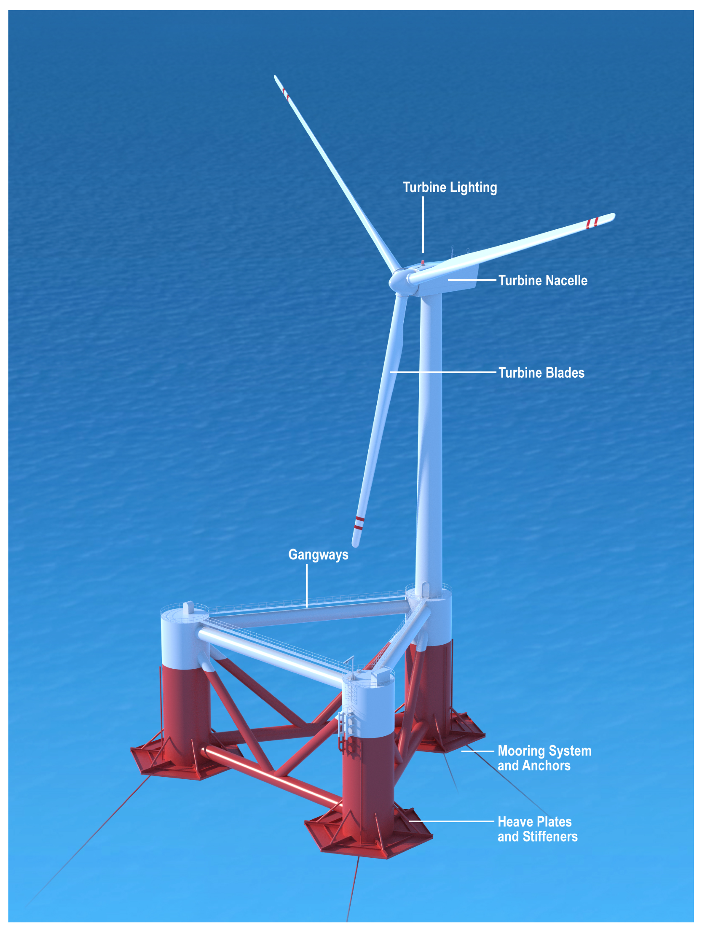
1]. Some prototype designs, e.g., Windfloat [
2] (
Figure 1) or a spar [
3] use heave plates to stabilize the platform in pitch, thus improving the power output of the wind turbine.
Experimental research is the main means to study the hydrodynamic characteristics of heave plates, although some computational fluid dynamics solutions have also been reported (see e.g., [
4,
5]). Scaled model tests can provide a good understanding on the behavior of floating platforms at various stages of design and development. This reduces risks and helps to optimize the design of the prototype platform. Hydrodynamic data on heave plates are usually reported using two non-dimensional characteristic parameters (Keulegan–Carpenter number
and frequency parameter
) that represent the amplitude and frequency of oscillation of any heave plate configuration [
6,
7,
8,
9,
10]. These dimensionless parameters of relevance are defined as [
11]:
Here, is the disk diameter, and f are, respectively. the heave amplitude and frequency of oscillation, and is the kinematic viscosity of the fluid.
Studies on the hydrodynamic coefficients of structures with heave plates have focused on obtaining values of these coefficients at parametric ranges of importance, as well as on behavioral trends with respect to
and
. Thiagarajan and Troesch in [
7] conducted model tests on circular columns of a TLP platform. It was found that, while the added mass coefficient was invariant at low
numbers at a fixed oscillation frequency, the heave damping coefficient was found to be linear when plotted versus
, and was made up of two components:
Friction drag: damping obtained by integrating the shear stress over the wet surface of the body. This damping is dependent on viscosity, hence on Reynolds number or . It is negligible except at very small numbers.
Form drag: term due to flow separation and vortex shedding at the edges. It is obtained by integrating the normal stresses over the wet surface of the body. It is highly influenced by the geometry of the body. They found this term to be linear with the amplitude of oscillation.
The same linear tendency of damping when plotted against
was also found in [
12]. In this study, experimental tests at low
were performed on a circular heave plate of 0.609 m diameter attached to a column of 0.457 m diameter. The experiments were performed at 1:75 scale by [
8] on a spar platform with two circular heave plates of 0.68 m and 0.60 m diameter. They also found that the heave damping was primarily form drag for low
numbers. The effect of
was found to be small for small
.
On the matter of vortex shedding flows, Tao and Thiagarajan [
5] studied the viscous flow around an oscillating cylinder with a heave plate by direct numerical simulations. Flows at
numbers ranging from
to 0.75 and at
were studied. Three different shedding modes were found, i.e. independent, interactive, and uni-directional vortex shedding. The occurrence of these modes was shown to be dependent on
and the aspect ratio represented by the ratio between the disk thickness
and the disk diameter
. The vortex shedding was found to be uni-directional for thinner disks at low
. A quantitative method of identifying the vortex shedding flow regimes based on
and aspect ratio was presented in [
6]). A distinct increase in damping, depending on the vortex shedding regime, was also observed.
The added mass effect was examined in detail in a number of publications. The added mass coefficient was found to have a weakly linear trend as the range of
was increased. The added mass of a circular plate attached to and separated from a column was studied by [
13]. The added mass coefficient was found to double when the plate was separated from the disk, but still largely invariant with
. A similar observation was also found by [
14], whose experiments covered a range of separation distances between the column and the plate. The authors also provided theoretical formulations for the added mass coefficient as a function of the separation distance.
The above observations largely apply to solid heave plates submerged in water and oscillating in isolation. On the other hand, proximity to a boundary, thickness to width ratio, the shape of the edge, and porosity of the heave plates can alter the behavior of the hydrodynamic coefficients. In [
9], experiments with 0.4 m rectangular heave plates were performed with different submergence from the free surface ranging from 0.4 to 1.2 m. The results showed that the added mass increased linearly with
but showed indifferent trend over the range of submergence tested (whose minimum value was one diameter). The drag coefficient—which is related to damping coefficient over
—was found to vary inversely with
, but showed similar invariant behavior with submergence. In all these cases, the effect of changing
was negligible over the ranges tested. Furthermore, the effect of ambient currents on the hydrodynamic coefficients of a plate attached to a column has also been studied (see e.g., [
12]).
When a heave plate is brought closer to a surface either by increasing the
value or by reducing the draft of the attached column, then some changes become apparent. Numerical studies by [
10] have shown that vortices shed by heave plates when executing large amplitude oscillations can disturb an otherwise quiescent free surface. They also showed that both coefficients exhibited dramatic variations with increasing
, which depended on the distance from the free surface. A similar behavior was also observed when a plate was moved close to a solid surface like a seabed. Energy dissipation arguments were used to explain damping variations that were observed when amplitude of oscillation was changed or when the free surface was proximal.
This paper arose out of an interest to know how waves on the free surface will alter the hydrodynamic coefficients of heave plates. To study this problem, we consider the forced heave motion of a column with a heave plate in the presence of waves. The problem is of relevance to floating offshore wind turbine design, where heave plates are attached to the columns of a semi-submersible. Because of the shallow draft of these structures, the heave plates are proximal to the water surface and, hence, wave induced water motions could affect the hydrodynamic behavior. In the next section, we present some theoretical background, followed by details of an experimental study that was conducted for this research.
2. Theoretical Model
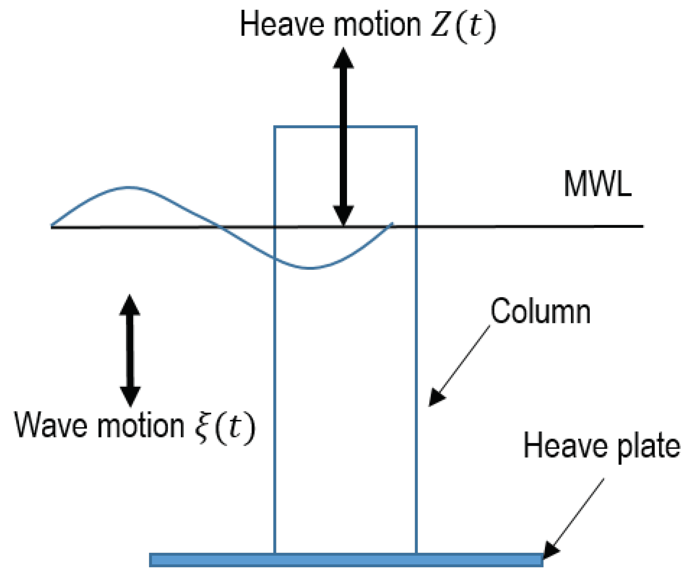
We initially consider a structure that is forced to harmonically oscillate in the vertical direction,
Z (heave) in still water,
Figure 2. Using Newton’s second law, the force
that is required to move the structure is shown as Equation (
3):
Subscript 3 denotes the heave direction,
M and
are the mass and heave added mass of the body, respectively, and
is the linearized heave damping coefficient.
is the heave hydrostatic restoring coefficient that depends on the water plane area
. The non-dimensional hydrodynamic coefficients are defined as:
where
is the theoretical added mass for a column with a disk attached at the bottom [
15].
and
are the column and disk diameters, respectively, and
.
The damping forces typically have a linear and a quadratic component [
12]. By using a linearized damping coefficient, the nonlinear effects are translated into a varying dependence on the coefficients
and
. A typical forced oscillation experiment in still water can be conducted in order to evaluate this dependence. A least squares method [
11] can be used to find the optimum hydrodynamic coefficients,
and
, which minimizes the error between the measured force during experiments (
) and the heave force (
) over
n samples (Equation (
3)):
The only unknowns in Equation (
5) are
and
. The displacement and the force are measured during the experiments. The velocity and acceleration can be obtained by numerically differentiating the displacement. By solving Equations (
6) and (
7), we obtain a system of two equations and two unknowns (
and
), which can be solved numerically.
A windowing method was used during the least squares process. In this method, the added mass and damping are evaluated in different cycles. First, the acceleration signal is divided into different windows with each one containing an acceleration peak. For each window, the added mass and damping are evaluated using the least squares method. The obtained damping coefficient is rejected at this stage, since it is poorly evaluated at acceleration peaks. This process is repeated over 32 cycles yielding the mean and the standard deviation of each coefficient through statistical analysis. The same procedure is done with the damping coefficient while using the velocity signal. This time the added mass is rejected, keeping the damping coefficient. This method was also used in [
16].
The relative kinematics between the platform and the water particles need not be considered when the platform is oscillating in still water. When the platform is oscillating in waves, the presence of the wave field alters the water particle kinematics near the edge of a heave plate. The resulting effect is complicated by the fact that the wave field itself is altered by the presence of the oscillating object. Furthermore, it is apparent that the motion of the object is caused by the forcing due to waves. In a linear sense, one can distinguish between radiation and incident/diffraction problems. In order to obtain suitable hydrodynamic coefficients for solving the radiation problem, one can use a linearized version of the relative velocity model described in [
17],
where
and
, respectively, represent the wave dynamic pressure acting on the top and bottom of the heave plate, and
and
are the water particle vertical velocity and acceleration respectively at the mean position of the plate. It can be verified that accounting for dynamic pressures on both surfaces of a disk is equivalent to using a relative motion in the restoring force term, i.e.,
.
If the wave kinematics at the mean position of the plate can be measured or estimated satisfactorily using a wave theory, then one can replace the Equation (
3) with Equation (
8) in the least squares analysis described above. One can then imagine two different approaches to evaluate the added mass and damping coefficients in the presence of waves:
Absolute model: this model is the same as the one used to evaluate the coefficients in still water. In this model the waves are not taken into account explicitly. Therefore, a variation is expected when comparing the obtained coefficients in waves with the ones obtained in still water. This model is akin to the default approach, and consistent with the linear superposition of radiation and incident wave problems.
Relative model: this model takes into account the presence of waves interacting with the heave plate. It includes the Froude–Krylov forces as well as the relative kinematics between the heave plate and the water particles. Here, the coefficients are explicitly made dependent on wave kinematics. This approach may be considered to be more appropriate for evaluating suitable coefficients.
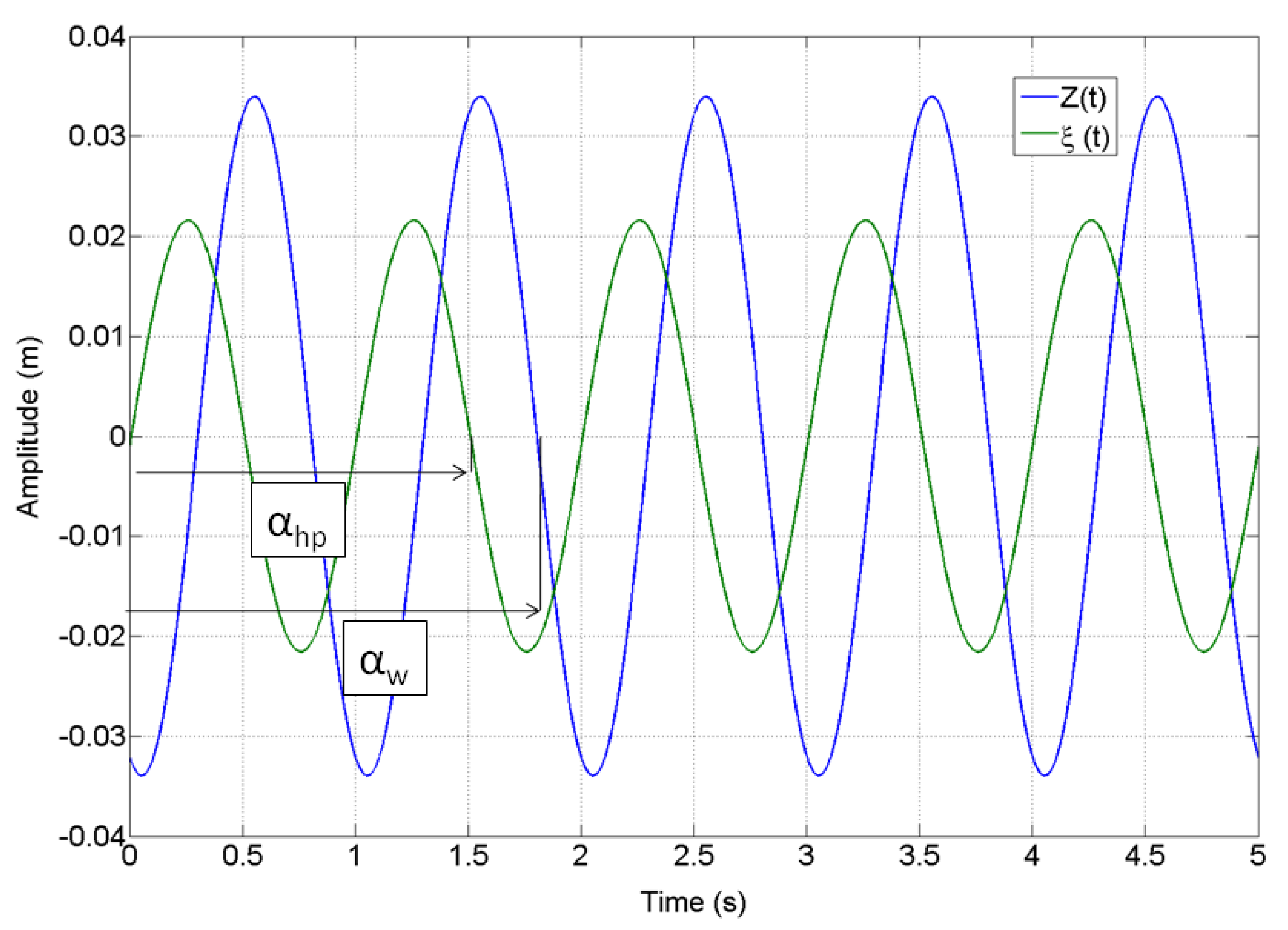
In the vicinity of a heave plate, the phase difference between the plate motion and the wave-induced water particle motion becomes a key parameter in the relative model. Let us, for example, consider the relative motion as:
where
By simple rearrangement, we can obtain
where,
and
. Thus, one could define a “relative”
number
This is similar to the relative velocity based
number mentioned in [
17].
3. Experimental Setup
A circular heave plate of diameter 0.25 m and thickness 4.3 mm attached to a column of diameter 0.088 m and draft 0.19 m is considered. This model is a 1:80 scaled version of a demonstration prototype off the coast of Spain reported in [
18,
19]. The experiments were performed at the Marine Ocean and Offshore Research (MOOR) wave tank facility at the University of Maine, which is 8 m long and 1 m wide. The water depth for the experiments was kept at 0.7 m. A wedge-shaped plunger type wave maker was installed at one end, and a passive energy absorbing beach at the other end. The wave maker is capable of producing regular waves from 0.5–2 s periods and amplitudes ranging from 0.002–0.132 m. The beach design was optimized to produce reflection of 5–10% over most of the range of testing.
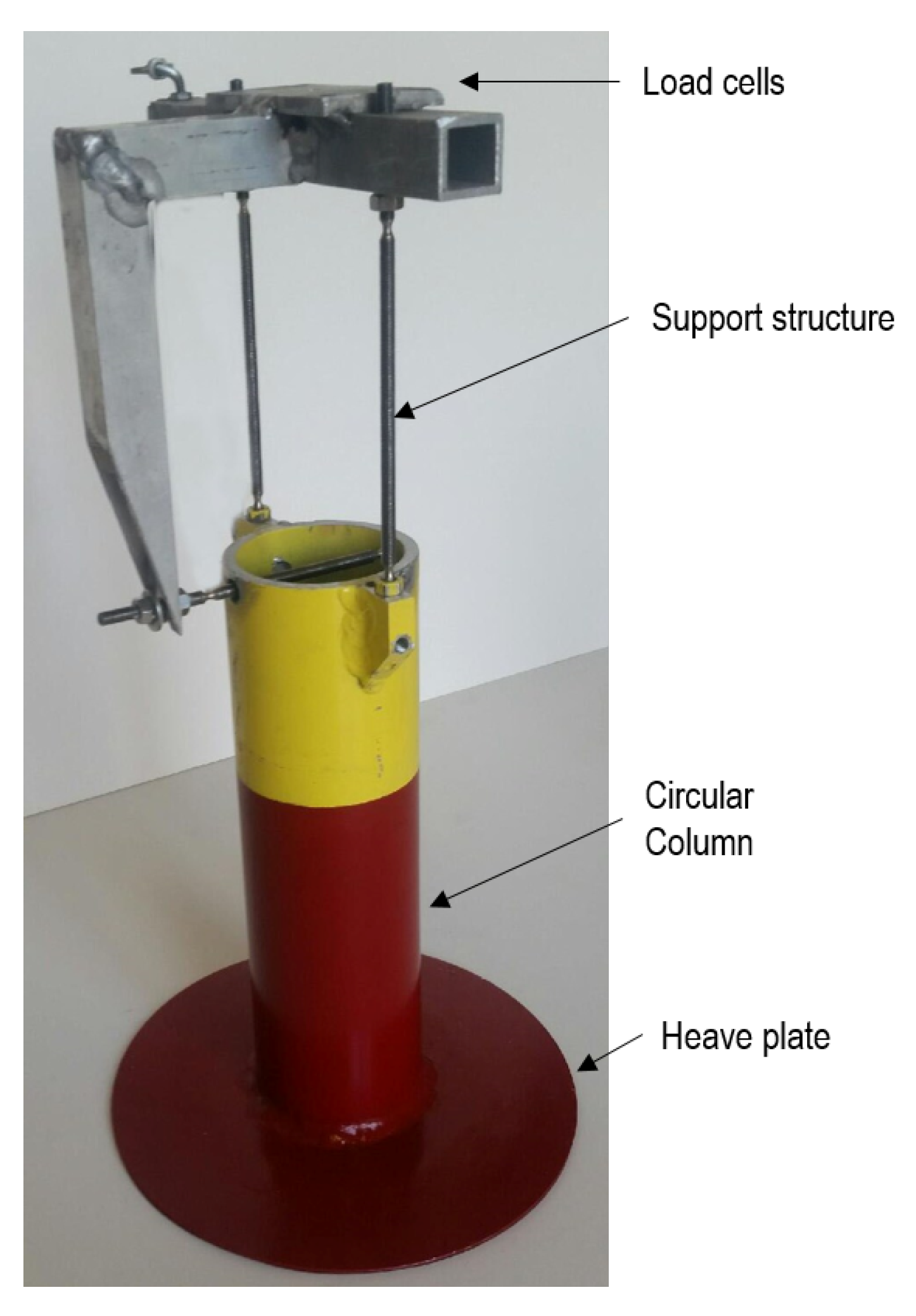
Forced harmonic oscillation of the models in the vertical direction was achieved while using a Parker ETH032 linear actuator driven by a 750 W Parker servo motor. Two Omega force sensors were attached by two slender rods to measure the vertical forces (
Figure 3). The heave displacement was measured by a string potentiometer. Output signals were amplified, sampled, and acquired at 1kHz. Using the least squares approach, the optimum hydrodynamic coefficients,
and
, which minimize the error between the measured force during experiments (
) and heave force (
) are found. A 32-cycle windowing method described in the previous section was used in the added mass and damping evaluation.
The first set of experiments was conducted in still water. The model was forced to oscillate over a range of
values from 0.05–1.2 at a frequency of 1 Hz (
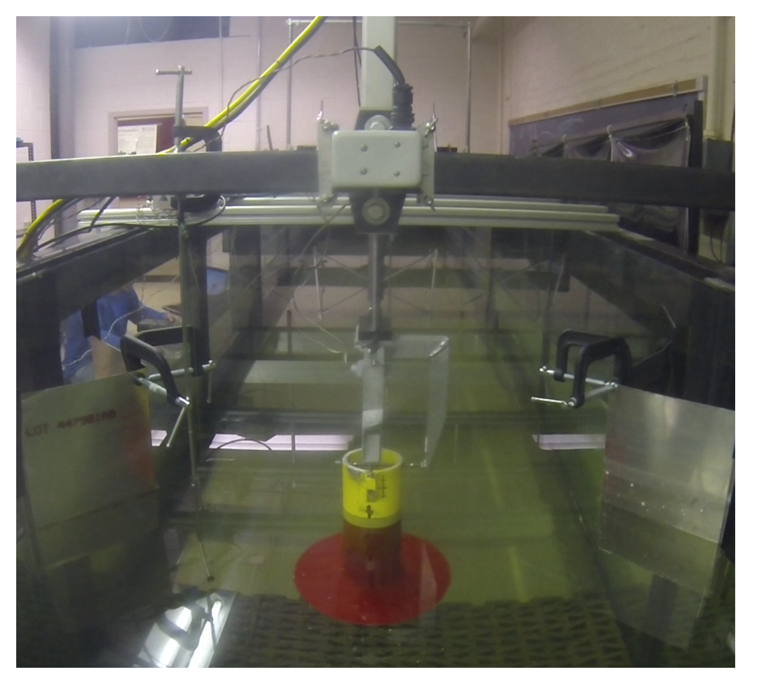
). At larger oscillation amplitudes, disturbance caused by the motion on the free surface radiated outwards. Two triangular wave deflectors were located on each of the tank walls at the heave plate location to reduce reflection from the side walls arising from the disturbance (
Figure 4). This simple device performed satisfactorily, as evidenced by Fourier analysis of the force time histories. This showed that several spurious peaks were present in the time histories recorded without the deflectors.
The second set of experiments were conducted in waves. The model was forced to oscillate at a frequency of 1 Hz and two
values of 0.5 and 0.84. The wave frequency was set at 1 Hz to match the heave plate oscillation frequency. The wave steepness varied from
.
Table 1 presents the experimental test matrix. The phase difference between the wave and the platform motion was introduced manually by visual observation of the first three waves measured by a probe located adjacent to the model. The heave plate motion was triggered when the third wave crest reached a desired distance from a zero phase mark. This approach resulted in several runs at different phases ranging from
to
. Each experiment was repeated for different phases in between this range in order to study the effects of the phase between the platform and the wave. In order to calculate the phase between the wave and the heave plate signal, a frequency analysis was performed using the platform displacement and the wave elevation signals, such as shown in
Figure 5.
The quality of the generated wave was tested with a repeatability test. The platform was replaced with a third wave probe to measure the wave field at the exact location of the platform. Each wave case was repeated three times. For each case, a statistical analysis was performed that yielded the mean and standard deviation of the wave amplitude and frequency.
4. Results
The added mass and damping coefficients for the wave experiments were obtained by two different approaches. In the "Absolute model" approach, Equation (
3) is used in the least squares evaluation. This model is identical to the still water case, and all wave-induced variations were visible in the trends of the coefficients with the phase angle. In the "Relative model" approach, Equation (
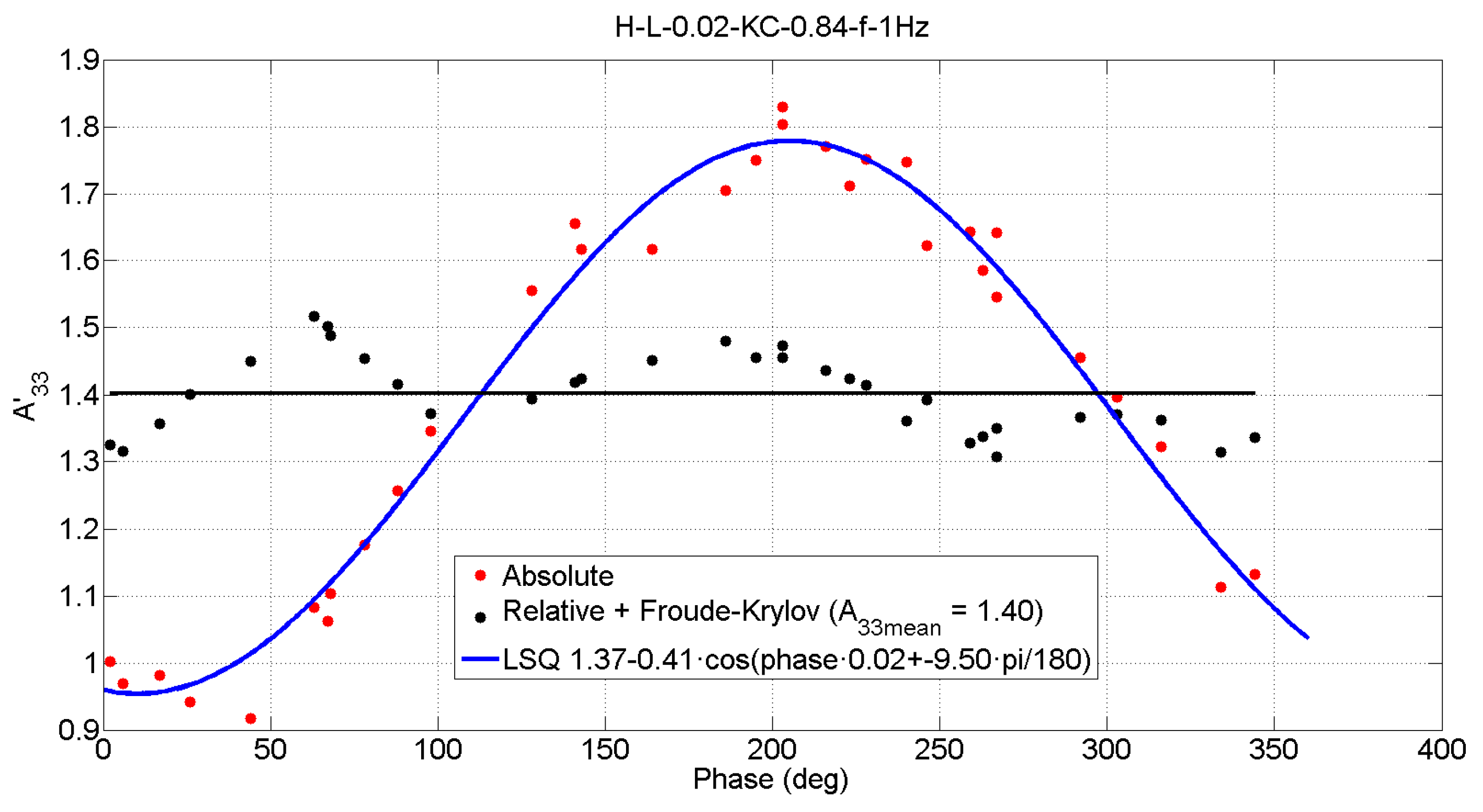
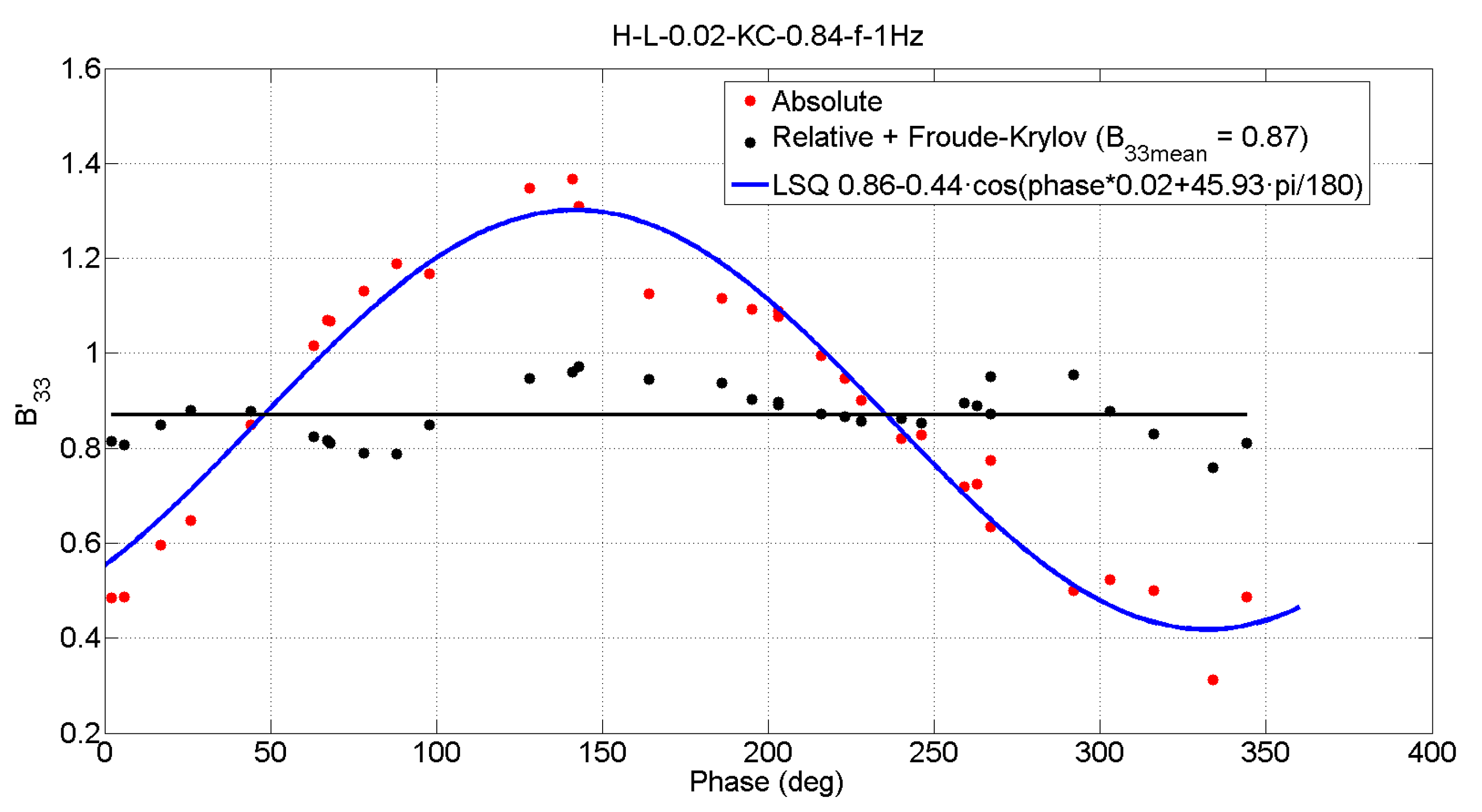
8) which incorporates relative kinematics is used. Sample added mass and damping results using the two equation models are shown in
Figure 6 and
Figure 7 for different phase angles at
and
. At this
value, still water added mass and damping values are 1.42 and 0.85, respectively.
When using the absolute model approach, a clear sinusoidal trend is observed with respect to the phase angle. Interestingly, the mean value of this sinusoidal variation matches with the corresponding still water added mass and damping values to within 3%. When the relative flow approach is used, the trend of both coefficients with the phase is much flatter, tending towards a constant value that matches the still water value to within 4%.
The relative phase between the plate and the wave gives rise to a relative change in the
, although the amplitude of oscillation is kept constant.
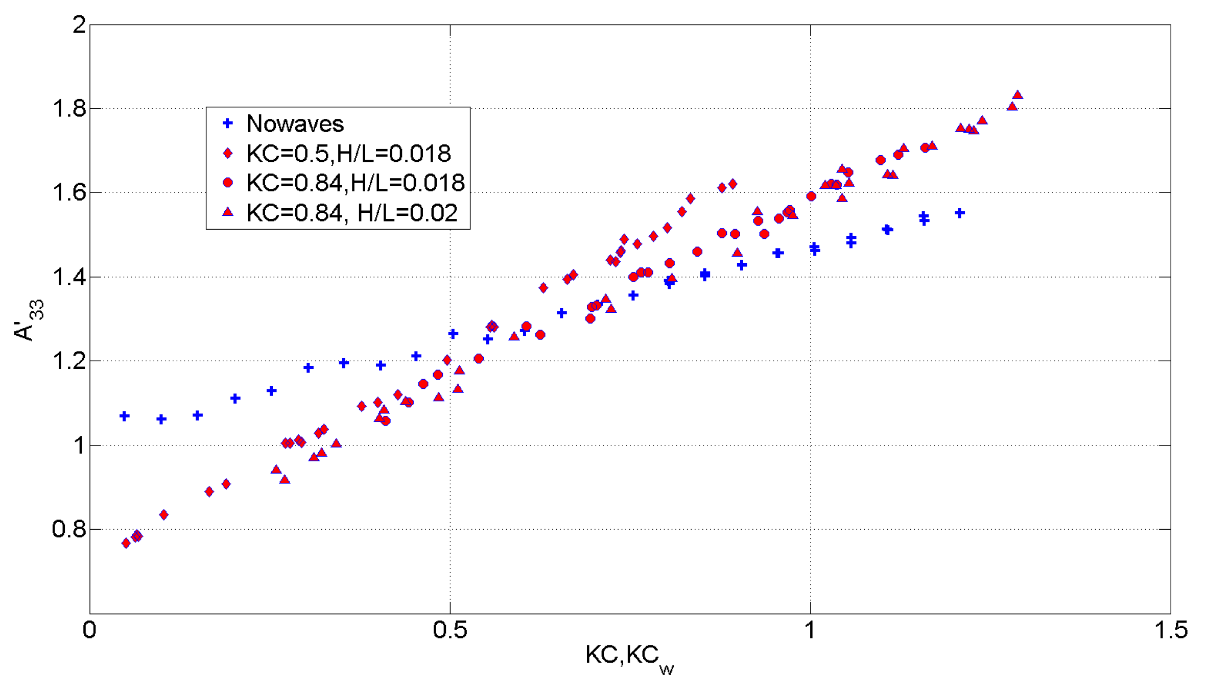
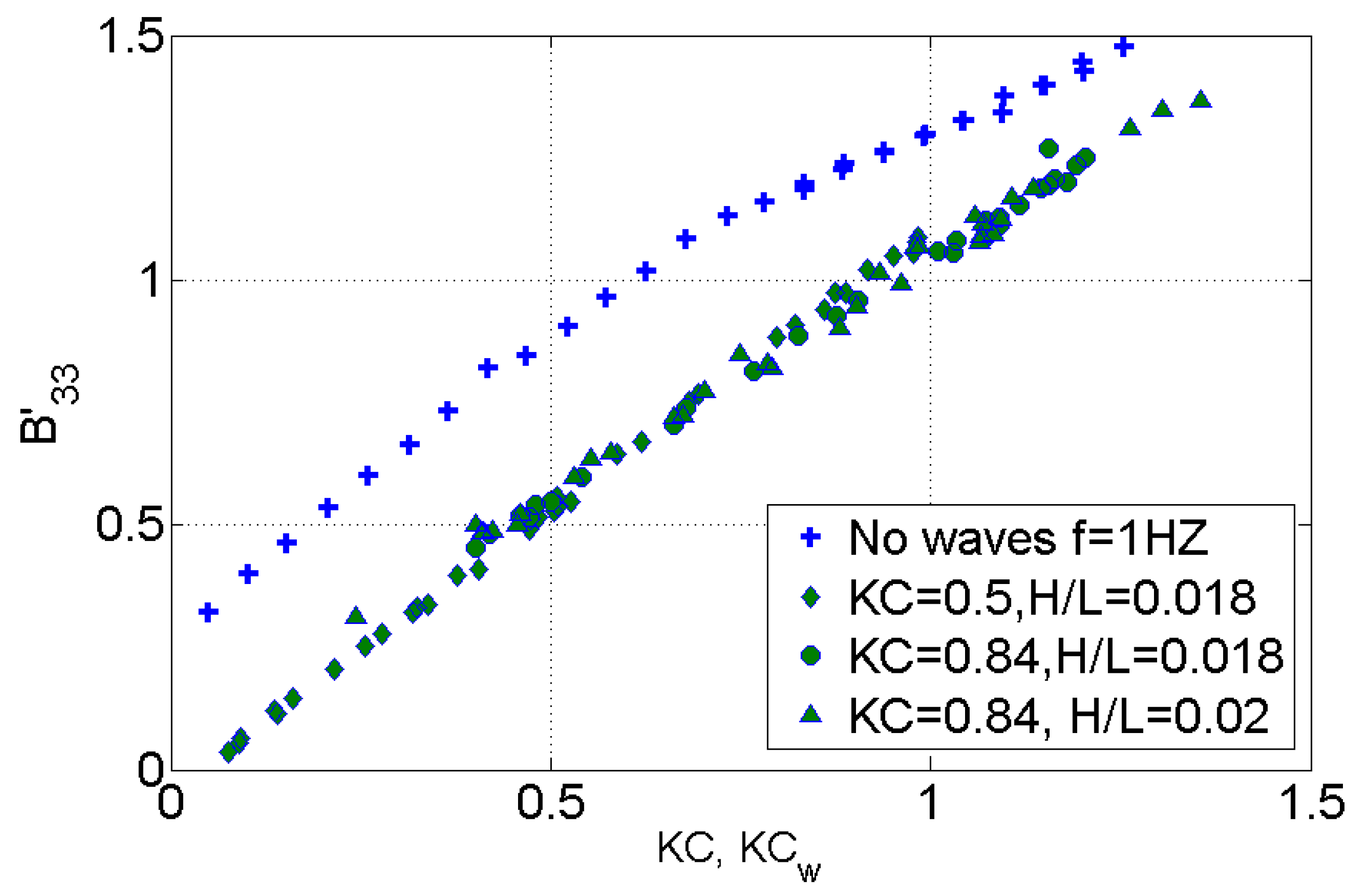
Figure 8 and
Figure 9 present the added mass and damping coefficients obtained using the relative model against
. Additionally shown are the results obtained in still water for the added mass and damping coefficients vs.
. The results are presented for the cases
and
for a frequency of oscillation of 1Hz and for
and
. The observed linear trend in the coefficients is remarkable. It can be seen that the added mass and damping coefficients increase as the relative displacement between the plate and the wave particles increases. The added mass coefficients in waves show a steeper linear trend when compared with the still water coefficients. For small
, the added mass coefficients in still water are higher. As
increases, the coefficients in waves become slightly higher than the ones in still water. The damping coefficients in still water and in waves are very similar in slope, with the zero offset showing a difference.
5. Discussion and Conclusions
This paper has focused on the effect of ambient wave motion on the hydrodynamic forces acting on an oscillating heave plate. When compared to the plate oscillating in still water, large differences in the values of the added mass and damping coefficients are observed. These differences are quite pronounced when the relative motion between the water and the plate are not taken into account. The results from
Figure 6 and
Figure 7 tend to indicate that applying the added mass and damping coefficients obtained from still water experiments for simulating the motion of a structure in waves may lead to inconsistent results. However, due to scarcity of data on oscillating plates in waves, one method of getting reliable added mass and damping values would be by using the newly defined
, which depends on the relative amplitude of motion with respect to the wave. As seen in
Figure 8 and
Figure 9, the trends between the results in waves are somewhat closer to those that were obtained in still water.
Because damping values are more critical in estimating the maximum motions around resonance, a relative phase angle of
may be used for
. This could be used iteratively along with motion magnitude to find the optimum damping coefficient. On the other hand, it is seen in
Figure 6 that, at around a phase angle of
, the added mass coefficients in waves and in still water are similar in magnitude. However, added mass coefficients are of relevance in all motion ranges. From
Figure 8, it is seen that, at lower
values, the added mass coefficients could differ by 30%, which can affect inertial load calculations. Thus, caution needs to be exerted in selection of hydrodynamic coefficients for heave plates oscillating in proximity to the free surface. More data would support better estimates of hydrodynamic coefficients for use in simulation of offshore wind turbine platform motions. Future work by the researchers would include a broader range of wave parameters and oscillation ranges. It is also envisaged that currents could be added to the environment in order to understand the combined effect of waves and currents.


