1. Introduction
With the development of offshore systems (wind farm, oil, gas, etc.), subsea cables and pipelines have become important communication channels through the maritime domain. The demands for such channels keep increasing, and hence the needs for trenching operations have grown rapidly in recent years [
1,
2,
3]. The practice of subsea trenching was initiated in the early 1950s [
4] with the aim to reduce the risk of hazards to subsea installations [
5,
6,
7]. The concept of subsea trenching has been developed over the years through the improvement of design and implementation techniques. Nevertheless, given the nature of the channeled area (marine environment), it is still challenging to capture some mechanisms associated with trenching process.
It is acknowledged that when subsea cables are not properly protected, they can be damaged, due to the seabed relief [
8], ship anchors [
9,
10,
11], icebergs [
12], industrial fishing activity [
13], and even shipping containers that sporadically fall from vessels [
10]. A statistical analysis conducted by the United States Department of Energy on 1061 submarine cable faults and accidents in numerous sea areas revealed that 82% of cables were harmed due to external activities, while the remaining damaged portion (i.e., 18%) was induced internally [
14].
Figure 1 presents the results of a recent survey on submarine cable faults, which confirm the hazards due to the external aggressions [
15].
Although different burial techniques have been devoted to risk reduction for seabed installations [
2,
5,
16], the selection of the appropriate trencher equipment depends on a number of factors. Among them, the properties of the soil from which the trench is to be excavated is the most critical for all the trenching tools [
17]. The mechanical systems generally represent the best option for stiff to hard clays and coarse-grained materials. They still have some difficulties to be implemented under certain conditions [
11,
18]. Jet trenching tools represent the "go-to" tools, which have advantages for sands and very soft clays [
17]. For instance, the remotely operated vehicle equipped with jets can operate in deep water, steep topography, and soft sediments, which are unfavorable for the other methods. Understanding the complex interaction between soft sediments and jet trenchers is vital for trenching operations. Nozzle distribution and water-jet properties have a direct influence on the construction performance, particularly, the trench geometry and excavation speed. This leads to the demand for construction optimization (efficiency of jetting devices) and robust soil-waterjet interaction analysis methods. These aspects have remained unclear to some extent. An inclusive overview of jet trenching technology and modeling is urgently needed to emphasize current research gaps and set the strategy for future development [
19].
Another non-negligible aspect of trenching technology is the trenching efficiency in deep water. Indeed, as the water depth of the working area increases (deep sea), the performance of these trenchers tends to be hampered by the low vehicle maneuverability [
20]. In such circumstances, an approach that guarantees the stability of the trenching operations is required, namely the jet trenching technique. Furthermore, due to its efficiency and cost-effectiveness, this method is increasingly adopted to meet the requirements of offshore operations (in soft soils) in both shallow and deep water. Hence, the different facets relating to this technology should be systematically understood.
This study presents the state-of-the-art review on jet trenching technology, with the objectives of: (i) providing a theoretical foundation for the application of the subsea jet trenching method; (ii) reviewing the essence of the accumulated experience as well as later engineering prototype development; and (iii) revealing the current gaps and discussing the future tendencies in terms of technological developments and waterjet–seabed interaction analysis.
2. General Overview
In general, on the basis of the operation mode, the trenching machines can be grouped into four major categories, including: (i) burial sleds, (ii) burial remotely operated vehicles (ROVs), (iii) tracked burial machines, and (iv) burial ploughs [
21] (see
Table 1).
2.1. Background
The origin of the aforementioned trenching machines can be traced back to several decades ago [
22]. Specifically, their developments were initiated in the 1970s with the construction of the first jet sled prototype, which was successfully applied to numerous trenching operations in the Gulf of Mexico [
17]. In spite of its large popularity (it was the only system operated in deep water until the early 1980s) [
4,
23], the practice of the jetting technique became infrequent in favor of ploughs and mechanical systems in the late 1990s. This change occurred in response to dissatisfactions arising from its limited protection and high operation cost. Indeed, between the late 1980s and early 1990s, extensive research resulted in the development of ploughs which were found to be quite cost-effective in hard ground. Importantly, in recent years, there has been a resurgence of interest for both jet trenching and mechanical systems. The resurgence of jet trenchers is mainly due to the development of remotely operated vehicle (ROV) technology; while the interest for mechanical systems arises from the construction of inter-array cables in hard ground conditions, where jet trenching is not practicable and where cable ploughs are less suited for a variety of reasons. Moreover, this regaining of interest is symbolized by the gradual competitiveness of jet and mechanical trenching machines on the trenching market.
2.2. Technical Challenges
Subsea burial projects are rarely achieved using a single trenching approach, since the seabed conditions vary greatly with depth and along the project route. In such circumstances, different burial technologies are adopted according to their different ranges of applications.
Figure 2 gives a synoptic of the capabilities of different trenching methods [
17]
2.2.1. Suitability for Soft Soils
Soft soil behavior can be very complex [
24,
25,
26,
27]. Empirical evidence suggests that in very soft soils, the rotating mechanism of mechanical cutting tools can be damaged when they get stuck in sand or clays soils, inducing a relatively high maintenance cost [
11]. Generally, the lack of mobility of certain trenching machines requires repositioning and recovery operations which affect the quality of trenches and leads to time loss. Moreover, in very soft sediments, the seabed surface can be too much disturbed, which may disable the normal progress of the trencher right after the first pass. The authors of reference [
18] have carried out a terra-mechanics-orientated investigation that substantiates these field experiences.
2.2.2. Efficiency in Deep Water
The ROV-based jet trenchers are often preferred to the other trenching methods in deep-sea soft soils regions, due to their excellent versatility and operability. In reality, except for some trenching tools such as cable ploughs and pipeline ploughs [
28,
29], conventional trenching devices are heavy and complex machines (with several moving units), which makes them difficult to be controlled in deep-water conditions [
30].
2.2.3. Risk to Cable
The risk of cable damage is another critical challenge usually faced during cable or pipeline burial processes [
31,
32,
33,
34,
35]. This risk is more significant for mechanical trenchers, but damages can also occur while operating other approaches like ploughing. For instance, the authors of reference [
36] reported an issue of this type during the implementation of a pipeline plough in soft soil. It was observed that the plough being placed on the pipeline caused a buckle as a result of its self-gravity loading the pipeline. The relevant repairs were carried out by hyperbaric welding, the operation of which is not only expensive but also risky. Jetting systems are more effective alternatives for the various reasons that will be discussed in the following context.
2.3. Environmental Impact
Although essential for the protection of subsea cables and pipelines, the trenching processes tend to cause significant (but recoverable) disturbances to the subsea soil. To some extent, these disturbances also tend to induce the reconsolidation of soil as observed in tunneling [
37,
38,
39,
40,
41,
42,
43,
44,
45,
46] and deep excavation dewatering [
47,
48]. Subject to water depth, sediment mobility, and soil type, the recovery from the waterjet trenching method can take place in several days to almost never. Compared to mechanical burial systems like ploughing, this recovery rate is slower and can be ascribed to the relatively high degree of disturbance caused by the jetting method. The recovery rate is largely reliant on the sediment supply as well as the capacity of currents and waves to erode transport and deposit seabed sediments. Then again, the availability of the sediments is dependent on the location of the trenching zone (nearshore, continental shelf, continental slope, etc.). An inclusive discussion on seabed recovery following trenching operations can be found in recent literature [
49,
50,
51].
3. The Jet Trenching Method
3.1. Principle
The jetting approach modifies the initial seabed matrix with high-speed water jets so that the heavier pre-laid ‘products’, cables, or pipelines sink to a pre-determined depth, dragged by their own weight [
52,
53,
54,
55]. As shown in
Figure 3, this modification is usually achieved through erosion/fluidization or cutting and relies on specific methodologies.
3.2. Jetting Approaches
A synopsis of jet trenching approaches is given in
Table 1. This section intends to provide complementary information on implementation processes. In reality, depending on the soil properties, the planned trench depth, the operating depth, and the operating distance, a variety of trenching procedures can be adopted, including sled and ROV jetting as well as mass flow excavation.
Figure 4 illustrates some of these techniques.
(i) The ROV jetting approach is usually conducted on shorter operation distances, limited to clays and sands, and can be executed in a water depth of 10 to 2500 m. The trenching vehicle (usually equipped with jetting arms) is first positioned on the soil in such a way as to straddle the pre-laid cables or pipes. Then, the jetting arms are deployed in a quasi-vertical position, where the water jetting is initiated. With the advance of the trencher, the erosion or fluidization mechanisms of the soil takes place along the leading edge of jetting arms, due to the high pressurized water (3~15 bars). The trenching machine is generally piloted (via using sonars, cameras, and sensors) by an operator installed on the vessel, which is also responsible for controlling and optimizing the construction efficiency according to the prevailing conditions [
59,
60,
61,
62]. Moreover, the trench clearance is controlled by low pressure waterjets injected from the back lower side of the jetting arms, as illustrated in
Figure 4a. The cutting ability of waterjets is mainly generated by powerful pumps installed on the trencher. With a total power fluctuating between 750 kW (Trencher T1000, Deep Ocean) to 2100 kW (Trencher UT-1, Deep Ocean), some ROV trenching machines can ensure the burial operations in one or more passes.
(ii) The burial by jetting sleds (
Figure 4a) is often carried out in shallow waters and on seabed conditions ranging from clays, sands, gravels, and sandstones. This approach works on two main principles. The first involves breaking up the soil via high speed water from jet nozzles; while the second involves the pumping of air into the pipe to enable the lifting of suspended materials away from the trenched location [
52].
(iii) The mass flow excavation process involves no physical contact between the seabed and the trenching tool (
Figure 4b), allowing pipelines to be exposed without risk of damage. This technique was initially introduced for non-contact dredging operations. Indeed, apart from trenching operations, this approach is also popular for backfilling as well as freespan and sandwave rectification. Generally limited to sand and very soft clays, the breaking mechanism in this case mainly relies on a large hydraulic flow that scours the seabed [
58]. Moreover, due to the requirement of a very high flow rate water jetting, the mass flow excavators are, as a rule, powered from the surface. In other words, this system is not fitted for deeper operations, due to the loss of hydraulic power.
This paper puts a particular focus on the ROV jetting devices, as they are increasingly adopted for trenching operations. Their major advantage is that they (some models) can perform both pre- and post-lay trenching, as well as direct cable lay and burial.
3.3. Jet Trenching Devices
Jet trenchers are large machines of variable dimensions, depending on the manufacturers and the requirements of operators. For example, a typical ROV equipped-jet machine (T1200, operated by Helix offshore) has a width over tracks of 5.60 m, a length of 9.15 m and a height of 5.16 m. Their weight in air (when they are equipped with tracks) can vary from 21,772 kg (Trencher T1000, Deep Ocean) to 57,153 kg (Trencher UT-1, Deep Ocean). However, once in the water, their weights are more significant and govern the buoyancy needed on the base trencher.
Figure 5 shows some recently developed jet trencher prototypes. In fact, the hydrodynamic, shape, and submerged weight of these jetting systems are continuously enhanced to provide optimal performances in difficult terrains. Using UT-1 Ultra trencher (Deep Ocean) as an example here. It is considered as one of the world’s most powerful jetting ROV, due to its 2.1 MW of total power, as well as its effective water pumps (up to 4 × 375 kW). Moreover, the UT-1 oscillating sword design allows a satisfactory performance in sand and clay.
Table 2 summarizes the main specifications and performance indicators of some commonly used waterjet burial machines. It should be noted that this inventory is not exhaustive, the principal objective of this section being to show some machines’ specifications and their range of application.
4. Properties of Subsea Sediments
The jet trenching vehicles are often deployed in shallow and or deep waters, where their efficiency applies to a wide variety of seabed materials [
66,
67,
68,
69,
70,
71,
72]. Nevertheless, soil conditions vary substantially according to the geographic regions (Asia Pacific, Europe, Middle East and Africa, Latin America, and North America). The soil index properties often fit into two main categories including the soil grain properties (grain size, mineralogy, geometry, and crystal structure) and soil aggregate properties (microstructure). This section discusses the properties of subsea sediments by stressing their influence on the jet trenching mechanism.
4.1. Classification and Behavior Characterization
Numerous offshore soils are formed in an analogous fashion as onshore soils, i.e., as an integral part of the rock cycle [
73]. To understand their behavior and basic properties [
74,
75,
76,
77], engineers routinely adopt the unified soil classification system (USCS) described either in the standards BS 5930 [
78], ASTM D 2487, or ASTM D 2488 [
79]. However, Thusyanthan has shown that some quantitative and qualitative differences may exist between these standards and result in cumbersome inconsistencies for very similar soils [
80]. These discrepancies are fundamental, as they may influence the reliability of design, per se, and should be given proper attention.
In theory, the behavior of the seabed sediment can be defined using a number of geotechnical parameters that include the particle size distribution, drainage conditions, soil state (normally consolidated/over-consolidated), stress history, and water content [
81,
82,
83,
84].
Figure 6 presents the offshore soils’ particle size distribution based on the BS 5930 classification system. This spectrum distribution is a representative of soil types prevailing in different subsea regions. However, merely relying on these parameters for setting up the trenching operation or performing related analysis can be sometimes misleading, due to the presence in these soils of some constituents that may affect their properties.
4.2. Geochemical Composition
The carbonate content is a critical index property for the performances of burial operations. Investigating the properties of the West Africa carbonate rich seabed sediments, the authors of reference [
86] have stressed an urgent need to integrate the determination of the carbonate content into the traditional seabed characterization routine. Similarly, Brunning and Machinremarked that carbonate materials are quite prevalent in the Asia Pacific [
17], but due to the lack of relevant expertise, associated trenching operations are still challenging. Indeed, in some cases, these materials can be very stiff and require the intervention of mechanical trenchers [
87,
88]. As a matter of illustration,
Figure 7 depicts a micrograph of a high carbonate clay specimen extracted in the West Africa region [
89]. The composition analysis infers that the soil structure is a random to dispersed, densely packed arrangement of silt-, clay-, and sand-sized minerals. It is suggested that the calcium carbonate acts as a cementitious agent among these elements and contributes to the enhancement of the material properties.
Empirical evidences have demonstrated that the carbonate content index can affect the properties of offshore soils in several ways. For example, Demars et al. state that the strength parameters of clay increase along with carbonate content [
86]. Their conclusion was substantiated by the work of [
90] that found some meaningful correlation between the effective cohesion of Marly clay and the carbonate content. From a general point, the soil behavior varies with increasing carbonate content from cohesive soils to granular soils.
4.3. Soil Breaking Profiles
As illustrated in
Figure 6, the effect of a high-pressure waterjet on the seabed can result in different trench profiles, depending on whether the trenching takes place in cohesive or non-cohesive soils. In cohesive soils, for example, the excavation slopes tend to be stable for high injection pressures, and U-shaped trench profiles are commonly obtained. With reference to the advance rate of the trenching machine, this excavation speed is, however, susceptible to be hindered by the soil resistance. On the contrary, V-shaped profiles are typical of non-cohesive soils. The slope collapse potential of the excavated trench is significant, even when a low waterjet pressure is applied. In this case, the construction efficiency can be usually enhanced and a wider trench geometry can be obtained, as illustrated in
Figure 8 [
91]. The effect of the waterjet on different subsea soil conditions by analyzing trench profiles in stiff clays, loose sands, dense sands, layered sediments can be found in [
51].
In reality, non-cohesive soils are relatively more susceptible to erosion than cohesive soils, due to the weak bonding between the soil grains. Owing to the high cementation force between the soil particles [
73,
93], high plasticity clays tend to be more difficult to be eroded than gravel soils. These clays generally break into lumps and pieces, in lieu of individual small particles, as is the case for granular soils [
94,
95,
96,
97]. This also explains the observation of the suspended soils being dispersed or deposited at various distances (100 to 2000 m) from the trench during the jetting [
51]. It also somehow implies the mechanism that affects the seabed recovery [
50].
5. Mechanisms of Jet Induced Trenching Operations
This section presents the water jetting, soil breaking process, and product sinkage mechanisms, which underpin the jetting-induced burial procedures.
5.1. Typical Design of Jet Arms
A typical design of ROV jetting devices fundamentally adopts two jetting arms, three jetting directions, and three cavities, as illustrated in
Figure 9 [
64,
92]. The twin jetting arms are considered for straddling cables or pipelines and breaking the soil along with the advance of the trenching vehicle. The inner width between the arms should thus be larger than the diameter of the cable to be buried. It is also observed that the jetting nozzles arranged on the ‘arms’ typically conform to three-directional configurations. High-pressure cutting nozzles are regularly placed on the principal face of the jet arms, while their inner side is equipped with a large flow-breaking nozzles and the bottom side with large flow-conveying nozzles. The corresponding nozzles in each direction are denoted as (1), (2), (3), respectively, in the section view A-A’ (see
Figure 9). Furthermore, the three-cavity design of the jet arms is to fulfill the function of soil breaking at different levels by supplying (independently) each type of nozzle with water. It should, however, be emphasized that the cross-sectional area of the water supply chamber is normally designed to match the pressure, flow rate, and number of nozzles required by the jet arm. In the sectional view B-B’ (see
Figure 9) that shows the water supply chamber, the cavities of interest are respectively labelled as I, II, and III.
In addition to the functional design features discussed above, the balance of reaction forces is another critical performance-reliant feature of the jetting tools. In this vein, Adamson and Kolle proposed a rearward-firing jets system to consider the reaction forces resulting from the cutting jets [
98]. In their system, oscillating nozzles were adopted to enhance the trenching performance in cohesive soils. Subsequently, Jones and Hirai developed a malleable thrust system and moving buoyancy structure to tackle the same issue [
99].
5.2. Soil Breaking Process
Generally, the burial depth is defined according to the severity of hazard risks to subsea installations [
101,
102]. On the other hand, the trench depth is largely dependent on the efficiency of jetting devices like the twin jetting arms.
Figure 10 shows an illustration of a mechanism involved during the jet trenching. Along with the erosion process, the mass of soil affected by the action of waterjets can be divided into three areas, namely (i) the cutting, (ii) crushing, and (iii) sediment transport areas [
103,
104]. (i) In the cutting area (zone I in
Figure 10), the action of waterjets is carried by the soil body directly in front of the jetting arms, whereby, the soil is initially undisturbed with a relatively high strength. To reduce friction resistance between the jet arms and the cutting wall, the design of the nozzles generally adopts a systematic inclination towards the inside and the outside of the cutting arm [
98]. (ii) The crushing area (zone II in
Figure 10) corresponds to the soil mass formed between the two arms, as a result of the cutting process. To be more specific, the original structure of the soil is destroyed by the cutting process, occasioning a rather large amount of suspended sediment and the reduction of soil strength. Furthermore, compared with the first stage, the breaking pressure is lower and the jet flow rate is higher. (iii) In the sediment transport area (zone III in
Figure 10), the soil volume stripped by the actions of cutting and crushing tends to drift behind the jet arms and settle under the gravity effect. Because this may adversely affect the installation of submarine products into the trench, large-flow jets are thus used to clear the trenched area. At this stage, the soil is completely disturbed.
5.3. Sinkage of Products in the Trench
The sinkage of a cable or pipeline in the trench is the key to using jet trenchers successfully. This mechanism depends on the bending stiffness and submerged weight of the products. As an example,
Figure 11 shows an illustration of the current generation of subsea cables [
21,
105].
Empirical evidence from manufacturers suggests that lighter cables rarely sink exactly to the required depth after the first passage of the trenching machine. The solution is to choose a conductor material (Element #1 in
Figure 11) with enough weight. In this case, the substantially higher specific weight of copper material (8900 kg/m
3) compared to aluminum (2760 kg/m
3) gives it a prominent advantage: sinking appropriately and more quickly into the location in the fluidized seabed.
It is clear that the behavior of the soil undergoing the action of the high-speed waterjet is, as well, greatly accountable for the success of the jet-induced burial process. In non-cohesive sediments, the injection of water into the soil matrix tends to increase the pore water pressure and diminish the effective stress. This explains that when the density of the pre-laid product is greater than that of the fluidized sediment, the cable or pipeline will sink into the trench. This principle also applies to the cohesive soils which, however, are characterized by a completely different breaking mechanism. It should be recalled that in this case, the trench construction involves a combination of three sediment matrix failures, including: (i) The shear failure of the seabed surface caused by the action of water jet, (ii) the bearing pressure failure induced by stagnant water from the injection process, and (iii) the hydro fracturing caused by the cavitation of sediment material and concomitant increase in water pressure [
51]. Complementary details will be provided in
Section 7 that discusses the waterjet-seabed interaction modeling.
6. Case Histories of Jet-Induced Burying Operations
6.1. Trenching Operation in Sand
6.1.1. Offshore Gas Project, Vietnam
The objective of this project was to install 107 km gas transport facilities in the South China Sea [
36]. The pipeline had a total diameter of 406 mm, including the walls and coating thickness. The operating depths ranged from 9 m to 46 m, while the burial depth was assumed to be the pipeline diameter added to one half. Geotechnical investigations revealed the presence of coarse sand overlying a stiff clay layer. This clay layer was very dense in place, with an undrained shear strength of approximately 70 kPa. Originally planned to be entirely trenched by the ploughing technique, the project finally incorporated the jetting approach for more challenging sections, mainly characterized by sand-wave spans. Yet, prior to the implementation of these methods, a pre-sweeping jetting sled (supported by a 1200 HP pump) was undertaken for reducing the sand wave size and allowing the smooth pipeline installation. Indeed, sand wave spans are disadvantageous for this process, as they can cause excessive bending which may result in the pipeline buckling. Regarding the jet-induced post-lay burying operation, the jetting sled mentioned above was found satisfactory through the project, with a trenching rate of about 1.5 km/day. Though, as the trenching sled sporadically encountered limestone and compacted coral layers, it was considerably slowed down, as this technique is not well suited for this type of sediment.
6.1.2. Control Cables Burial Operation, Australia
The reported case involves the burying of a control umbilical to a target depth of 1 m along the Australian shelf [
17]. The cable had a specific gravity of 1.9 and an outer diameter of 115 mm. Due to the variability of soil properties along the project route, it was divided into different zones corresponding to different trenching approaches. The jetting approach was implemented via the T1 trenching machine [
64] in zones that were found to have more favorable conditions for such operations. Nevertheless, these zones were dominated by carbonate sandy silt or silty sand layers with a relative thickness of 10 m. These sediments were found at water depths of approximately 80 m to 100 m, corresponding to the operation depth. The combination of all of these conditions allow achieving a successful trenching operation, with an average trenching speed of 200 m. Although satisfactory along the trenching route, the burial performance was found rather poorer in areas presenting carbonate sediments.
6.2. Trenching Operation in Clay: Sheringham Offshore Wind Farm, United Kingdom
The Sheringham Shoal offshore wind farm is a green energy project that was implemented in the United Kingdom during 2009–2011 [
106]. The jet trenching approach was undertaken by different contractors to bury the inter array network of cables connecting the wind farm turbines. The water depth at the wind farm ranged approximately between 15 m and 22 m, while the maximum burial depth was set to 3 m. The geological profile of the site was mainly composed of medium sand and clays, which share some common characteristics such as high stiffness and high shear strength [
106]. Moreover, the densely compacted state of the sand and the heavily over-consolidated state of clays dictate the behavior of these soils [
107]. One section of the project was carried out by the “Contractor #1” that adopts the tracked T1200 waterjet trenching system (see
Figure 5b) for the cable burial operations. This jetting system has the advantage of maximizing the water pressure and flow distribution at the nozzles (
Figure 12). This prototype successfully achieved the trenching of a distance of 49.97 km in 62 days, i.e., an average speed of 805 m per day.
However, as previously mentioned, more than one contractor worked on the Sheringham Shoal project rather than just Contractor #1. The other contractor (“Contractor #2”) encountered issues whilst trying to jet in the stiff clays (London clay has a strength of about 100 kPa and very plastic). The surface fed jet trencher which was used in turn scoured large holes in the seabed when sandier conditions were encountered, resulting in issues associated with the creation of freespans [
108].
6.3. Discussion
Depending on the prevailing subsea conditions, i.e., the presence of sand waves, stiff carbonate sediments, hard soils, or very soft sediments, pipelines and/or cable burial projects are routinely divided into different sections to be trenched using the appropriate technique. In this vein, the engineers involved in the above discussed case histories remarked that the accurate soil characterization is essential to define the most suitable equipment [
17,
36,
92]. With values of undrained shear strength that can reach, for example, ~100 kPa in clay, subsea soils can be considered as very stiff. In particular, the second case study stresses the need to enhance the understanding of carbonate sediments given their determinant role in the success of jet trenching operations. Besides, there is no doubt that such operations require adequate tools.
Regardless of the operating depth, the jetting sled (shallow water) and ROV equipped jet (deep water) could achieve the successful trenching of pipelines (case 1) and cables (cases 2 and 3). Specifically, the hydrodynamic-based design of the shape of T1200 jet trencher gives it an enhanced stability in high currents. Additionally, the high-pressure jets produced by this prototype can enable a satisfactory performance in soils with strength up to 150 kPa. It should be noted that the implied burial speed of 805 m/day or 33 m/hr (in the last case study) is not representative of a typical trenching vehicle, which would normally trench at around 200–400 m/hr in sands. In fact, this was the first project for T1200, so it can be inferred that some initial issues associated with the machine operation have been addressed. Regarding the sinkage of the products in the trench, the choice of a pipeline with a specific gravity of 1.9 (case 2) was found fairly judicious given the conclusions of recent experiments [
109,
110,
111,
112]. Experimental studies had speculated that the specific gravity of the disturbed soil behind the trenching machine varies approximately between 1.6 and 1.8, with the minimum safe requirement being the lower values [
17].
Overall, the jet trenching operations should be carefully tailored in a manner to satisfy not only the project requirements but also the industry standards. Indeed, these codes are quintessential, as they provide acceptance criteria and technical provisions for general use by the industry, enabling an efficient risk management. The widely adopted industry standards for subsea trenching include the Det Norske Veritas—Germanischer Lloyd (DNVGL) [
113], American Petroleum Institute (API) [
114], and International Organization for Standardization (ISO) [
115] standards. By bridging cutting-edge theory with hands-on experience, these standards allow practitioners to benefit from an all-inclusive understanding of the subsea systems. Concomitantly, it is urgently required to lift the curtain on the modeling of the relevant mechanisms involved during the jetting process, with the goal of providing robust optimization alternatives to jet trenching procedures.
7. Jet Trenching Modeling
Although the relevant information pertaining to the trenching mechanism can be gathered via monitoring the trencher operations, the visualization and analysis of the sediment motion have remained challenging in real conditions. A number of studies have attempted to fill this gap by performing physical experiments and establishing some performance models. It should be noted that the existing modeling approaches pertaining to the jet trenching mechanism are essentially analytical. This section presents some of these methods without detailing the adopted experimental settings which can be found in the original papers [
116,
117,
118,
119,
120,
121].
7.1. Sand Models
The existing experimental studies on the trenching process in sand have shown a consistency regarding the mechanisms involved [
116,
117,
118]. In fact, the erosion/fluidization of sand was found to be related to its relative density, while the transport of sand and resedimentation processes were associated to the grain size. In particular, the authors of reference [
117] found that the travelling jet creates a dynamic (as it evolves with time
t) cavity with a diameter
d and a depth
hd at its opening. They estimated the diameter
d and depth
hd as follows:
where
represents the specific gravity of the seabed material,
is the acceleration gravity,
stands for the jet velocity,
is the jet diameter, and
is the representative size of the sediment.
7.2. Clay Models
Similarly, laboratory and field investigations on stiff clay [
16,
71,
119,
120,
121] have exhibited convergent conclusions regarding the jet trenching mechanism. The jet cutting process was found to be governed by the undrained shear strength. Besides, the breaking and transport of clay lumps were related to the soil plasticity, while their (clay lumps) deposition was found to be influenced by the soil unit weight. Acknowledging the following empirical assumptions: (i) Stagnation pressure causes bearing failure), (ii) exposure time governs the depth of cut for the static jet and (iii) traverse velocity governs the depth of cut for the moving jet, the authors of reference [
119] proposed a simple jet impingement model. Basically, they combined the equations of the bearing capacity
and the stagnation pressure
. This model attempts to predict the penetration at which the traveling jet will induce the material failure. These equations are given as follows (see Equations (3) and (4)), where
is a function of the impinging jet diameter and penetration.
where
represents the undrained shear strength of the sediment,
is the bearing capacity factor,
stands for the overburden pressure,
is the water density,
represents the velocity at the nozzle,
is the penetration, and
is the radius of the nozzle.
Unlike the previous approaches, which were mainly based on the bearing capacity theory, the authors of references [
16,
110] proposed a solution founded on the erosion failure mechanism. To predict the ultimate trench depth in clay, they proposed first computing the jet-soil interface trajectory, and then, evaluating its associated distribution of boundary shear stress. The ultimate depth is subsequently taken as the point where the critical shear strength is equal to the wall shear stress. This yields the following equation (Equation (5)), where
is the unknown to be found:
In this equation, is the nozzle diameter, is a coefficient obtained through experiments, represents the jet velocity, correspond to the nozzle translational speed, is the density of water and are coefficients. More details can be found in the original paper.
In general, although being relatively complex and non-straightforward, the aforementioned models can still provide satisfactory guidelines to the engineering practices. However, engineers should keep in mind that a concern often associated with empirical models is that they do not perform well out of their calibration spectrum [
122,
123,
124,
125,
126]. In addition, it is believed that numerical simulations [
83,
127,
128,
129,
130] can be engrafted to these procedures for providing substantiation to the relevant theories [
131,
132], offering insights to experimental results [
109,
110,
133], and being helpful in the clarification of new phenomena.
7.3. Perpectives: Paricles-Based Numerical Methods
Jet trenching modeling lies in the realistic description and quantification of the waterjet-seabed interaction. While it is true that the analytical methods can provide acceptable approximations of the trench characteristics, it is also true that under certain circumstances, they may deliver suboptimal solutions owing to some intrinsic limitations. Indeed, the analytical models cannot simulate the incremental construction process of trenches, i.e., they are not able to fulfill the non-uniform strain state of the soil undergoing the action of high-pressure waterjet. Moreover, the analytical models treat the soil as a continuum, and consequently, they cannot simulate some fundamental behaviors of the soil that arise from its particulate nature. Accordingly, numerical simulations are usually adopted for supplementing the analytical models [
134,
135,
136,
137,
138].
At present, very few studies have focused on the numerical simulation of waterjet-seabed interaction for optimizing trenching operation (efficiency of jetting devices) and understanding hidden physics (e.g., hydro-fracturing or fluidization) associated with this mechanism. The existing methods [
91] are mainly based on computational fluid dynamics (CFD). However, for real cases like subsea trenching, the reliability and suitability of CFD-based models can be questioned, due to several shortcomings. These limitations include the non-convergence of the model, strong discontinuities of the domain, and the non-consideration of real variabilities (the pore water pressure fluctuation, soil particulate nature, multiphase soils, etc.). For instance, it is critical to model the soil as a two-phase material given the conditions within which the trenching operations are conducted (fully saturated). This modeling scheme enables the water and the soil skeleton to move according to the constitutive behavior and the interactions between them. Therefore, promising numerical computation paradigms such as the smoothing particle hydrodynamics (SPH) [
139,
140] and material point method (MPM) [
141,
142] could be ideal alternatives.
7.3.1. Smoothed Particle Hydrodynamics (SPH)
The smoothed particle hydrodynamics [
143,
144,
145,
146,
147,
148,
149] is a particle-based numerical method increasingly utilized in fluid and soils mechanics to predict highly strained motions. One of the main attractive features of the SPH is its consistency with Lagrangian mechanics in terms of conservativity. The method relies on the use of a smoothing ‘kernel’ function that is particularly suited for discretizing the derivatives of continuous fields. The fundamental idea behind the SPH formulation is that numerical results rely on an interpolation process to describe both the space and time evolution of a given system. Basically, the domain of interest is discretized into a collection of macroscopic particles, each of which independently carries the system properties (density, velocity, mass, stress tensor, etc.). The behavior of a particle
i is determined through an interpolation process with respect to its neighboring particles
j within a given influence domain (
Figure 13). The particles have a spatial distance
h (usually termed smoothing length), over which their properties are approximated by using the aforementioned ‘kernel’ function
W. The intrinsic Lagrangian attributes of the SPH allows the simulation of complex hydrodynamic problems that involve large deformations and discontinuities, such as the soil erosion by high pressure waterjet. The SPH-based analysis of water-soil interaction was pioneered by [
139], but an enhanced modeling approach was later proposed by [
140]. This paradigm particularly suits for the jetting-induced trenching operation because it enables the modeling of saturated soils at a particulate level, as well as the interaction among particles. Besides, this realistic modeling approach has the prominent aptitude to allow the qualitative and quantitative motoring of the phenomenon variabilities [
150,
151,
152,
153,
154,
155,
156,
157,
158,
159,
160].
7.3.2. Material Point Method (MPM)
The material point method (MPM) [
141] is another particle-based method that discretizes the material domain into a group of particles, and enables them to deform according to Newton’s laws of motion. As illustrated in
Figure 14, the MPM uses moving material points (or particles) and computational nodes on a background mesh. The hybrid nature of the MPM (Eulerian–Lagrangian) allows the Cartesian grid to mechanize the treatment of fracture and self-collision. The MPM procedure can generally be decomposed into four main steps [
161]: (i) The problem domain is first represented by a finite number of particles characterized by state vectors (velocity, volume, mass, etc.), which are projected to the nodes of the computational grid (
Figure 14a). (ii) Then the governing equations are solved onto the nodes, providing updated nodal positions and velocities (
Figure 14b). (iii) Subsequently, the updated nodal kinematics are interpolated back to the particles (
Figure 14c). (iv) Afterwards, the particles state is updated, and the computational grid reset (
Figure 14d). Characteristic of both the Lagrangian description and the Eulerian description, the MPM represents the go-to modeling approach for hypervelocity impact problems which involve extreme large deformation. Besides, recent studies have demonstrated its prominent aptitude to model two phase materials, i.e., water-soil mixtures [
161,
162,
163].
Comparatively speaking, due to the lack of explicit connectivity between the particles, the topology change of MPM is as easy as that of SPH. Yet, in terms of computing performances, these two methods are comparable and believed to be suited for the analysis made upstream of the jet trencher performance enhancement effort. For a thorough comparison of these two approaches, the reader can refer to [
164]. Besides, the combination of these two powerful methods has been recently explored by Ma et al. [
165].
8. Concluding Remarks
This review presents the state-of-the-art jet trenching technology for the construction of seabed facilities. A comprehensive overview of the subsea jet trenching technology is presented, followed by a systematic discussion on the modeling and future development perspectives. The main conclusions are as follows:
(1) The jet trenching operations are usually undertaken to achieve the protection of subsea facilities. The latter depends mainly on the trenching procedures (jetting-ROV, jetting-sled, and mass excavator flow) that involve different mechanisms, depending on whether the operation takes place in sands (erosion/fluidization) or in clays (cutting).
(2) The performance of the jet trenchers on product burial is greatly dependent on the operation depth, soil conditions, the machine, and products specificities. When operating at a very large depth (1500–3000 m), most available models can achieve a maximum burial of 3 m within soils ranging from sand to stiff clays.
(3) The success of jet trenching operations also depends on the ability to accurately characterize the seabed sediments. More importance should be given to the microstructural/geochemical characterization of the seabed materials, especially to define their carbonate content. The case histories, as well as some studies, have shown that carbonate materials are susceptible to hampered trenching operations, due to a lack of expertise.
(4) The jetting arms represent the prominent unit of the jet trenching machine, given its importance in controlling the general characteristics of the trench. Their optimization has a determinant impact on the construction efficiency and has been a focus of recent technological efforts (waterjet–seabed interaction modeling).
(5) The modeling of the jet-induced trenching mechanism is still challenging and needs to be explored. Although performing satisfactorily, the available models are indirect and empirical. The SPH-based and MPM-based analyses of the waterjet–seabed interaction are bound to provide meaningful insights into the investigation of subsea soil erosion and cutting processes.
Author Contributions
The individual contributions of the authors are as follows: P.G.A.N.: Conceptualization, investigation, and methodology, writing—original draft; Q.Z.: Validation, editing; N.Z.: Data curation, editing; Y.-S.X.: Visualization, supervision, project administration. All authors have read and agreed to the published version of the manuscript.
Funding
The research work described herein was funded by the Research Funding of Shantou University for New Faculty Member, grant No. NTF19024–2019 and the National Natural Science Foundation of China (NSFC) (Grant No. 41672259). This financial support is gratefully acknowledged.
Acknowledgments
The aforementioned sources of financial support are gratefully acknowledged.
Conflicts of Interest
The authors declare no conflict of interest.
Abbreviations
| API | American Petroleum Institute |
| ASTM | American Society For Testing And Materials |
| BS | British Standard |
| CFD | Computational Fluid Dynamics |
| DNVGL | Det Norske Veritas Germanischer Lloyd |
| DSV | Dive Support Vessel |
| EPR | Ethylene Propylene Rubber |
| HP | Horsepower |
| ISO | International Organization For Standardization |
| MPM | Material Point Method |
| ROV | Remotely Operated Vehicle |
| SEM | Scanning Electron Microscopy |
| SPH | Smoothed Particle Hydrodynamics |
| USCS | Unified Soil Classification System |
Nomenclature
| diameter of dynamic cavity |
| nozzle diameter |
| representative size of the sediment |
| experimental coefficient |
| acceleration gravity |
| depth of the cavity |
| bearing capacity factor |
| overburden pressure |
| bearing capacity |
| radius of the nozzle |
| specific gravity of the seabed material |
| undrained shear strength of the sediment |
| injection time |
| jet velocity |
| nozzle translational speed |
| penetration depth |
| stagnation pressure |
| water density |
References
- Vu, M.T.; Choi, H.S.; Kim, J.Y.; Tran, N.H. A study on an underwater tracked vehicle with a ladder trencher. Ocean Eng. 2016, 127, 90–102. [Google Scholar] [CrossRef]
- Vu, M.T.; Jeong, S.K.; Choi, H.S.; Oh, J.Y.; Ji, D.H. Study on down-cutting ladder trencher of an underwater construction robot for seabed application. Appl. Ocean Res. 2018, 71, 90–104. [Google Scholar] [CrossRef]
- Drumond, G.P.; Pasqualino, I.P.; Pinheiro, B.C.; Estefen, S.F. Pipelines, risers and umbilicals failures: A literature review. Ocean Eng. 2018, 148, 412–425. [Google Scholar] [CrossRef]
- Palmer, A.C.; King, R.A. Subsea Pipeline Engineering, 2nd ed.; PennWell Corporation: Tulsa, OK, USA, 2008. [Google Scholar]
- Noad, J. Successful Cable Burial—Its Dependence on the Correct Use of Plough Assessment and Geophysical Surveys. In Offshore Site Investigation and Foundation Behaviour, Conference Organized by the Society for Underwater Technology, London, UK, 22–24 September 1992; Ardus, D.A., Clare, D., Hill, A., Hobbs, R., Jardine, R.J., Squire, J.M., Eds.; Springer: Dordrecht, The Netherlands, 1993; pp. 39–56. [Google Scholar]
- Johnson, L.G.; Heezen, B.C. Natural hazards to submarine cables. Ocean Eng. 1969, 1, 535–553. [Google Scholar] [CrossRef]
- Carter, L.; Gavey, R.; Talling, P.J.; Liu, J.T. Insights into submarine geohazards from breaks in subsea telecommunication cables. Oceanography 2014, 27, 58–67. [Google Scholar] [CrossRef] [Green Version]
- Liu, Y.; Bergdahl, L. Influence of Current and Seabed Friction on Mooring Cable Response: Comparison between Time-Domain and Frequency-Domain Analysis. Eng. Struct. 1998, 19, 945–953. [Google Scholar] [CrossRef]
- Gao, Q.; Duan, M.; Liu, X.; Wang, Y.; Jia, X.; An, C.; Zhang, T. Damage assessment for submarine photoelectric composite cable under anchor impact. Appl. Ocean Res. 2018. [Google Scholar] [CrossRef]
- Yoon, H.S.; Na, W.-B. Safety assessment of submarine power cable protectors by anchor dragging field tests. Ocean Eng. 2013, 65, 1–9. [Google Scholar] [CrossRef]
- Allan, P.G.; Comrie, R. The Selection of Appropriate Burial Tools and Burial Depths; SubOptic: Kyoto, Japan, May 2001; p. 8. [Google Scholar]
- Clark, J.I.; Chari, T.R.; Landva, J.; Woodworth-Lynas, C.M.T. Pipeline route selection in an iceberg-scoured seabed. Mar. Geotechnol. 1989. [CrossRef]
- Ellinas, P.; King, B.; Davies, R. Evaluation of Fishing Gear Induced Pipeline Damage. In Proceedings of the Fifth International Offshore and Polar Engineering Conference, San Francisco, CA, USA, 11–16 June 1995; Chung, J.S., Sayed, M., Gresnigt, A.M., Eds.; pp. 134–141. [Google Scholar]
- Tate, K.W.; Tudor, W.; Eaton, R. Protecting Submarine Cables from Accidental Damage. In Proceedings of the Offshore Technology Conference, Houston, TX, USA, 3 May 1982. [Google Scholar]
- Kordahi, M.E.; Stix, R.K.; Rapp, R.J.; Sheridan, S.; Lucas, G.; Wilson, S.; Perratt, B. Global Trends in Submarine Cable Systems Faults; SubOptic: Kyoto, Japan, 2016; pp. 1–7. [Google Scholar]
- Zhang, S.; Ge, T.; Zhao, M.; Wang, C. The prediction of traveling jet trenching in stiff clay based on the erosion failure mechanism. Mar. Georesources Geotechnol. 2017, 35, 939–945. [Google Scholar] [CrossRef]
- Brunning, P.; Machin, J. Applications and performance of trenching technologies in Asia-Pacific. In Proceedings of the Annual Offshore Technology Conference-ASIA, Kuala Lumpur, Malaysia, 25–28 March 2014; pp. 1447–1462. [Google Scholar]
- Morgan, N.; Cathie, D.; Pyrah, J.; Steward, J. Tracked subsea trencher mobility and operation in soft clays. In Proceedings of the International Offshore and Polar Engineering Conference, Lisbon, Portugal, 1–6 July 2007; pp. 1366–1373. [Google Scholar]
- Wang, Z.F.; Shen, S.L.; Modoni, G. Enhancing discharge of spoil to mitigate disturbance induced by horizontal jet grouting in clayey soil: Theoretical model and application. Comput Geotech. 2019, 111, 222–228. [Google Scholar] [CrossRef]
- Wang, M.; Wu, C.; Ge, T.; Gu, Z.M.; Sun, Y.H. Modeling, calibration and validation of tractive performance for seafloor tracked trencher. J. Terramechanics 2016, 66, 13–25. [Google Scholar] [CrossRef]
- BERR. Review of Cabling Techniques and Environmental Effects Applicable to the Offshore Wind Farm Industry: Technical Report; Department for Business Enterprise & Regulatory Reform: London, UK, 2008; p. 159. [Google Scholar]
- Biberg, O.; Åril, B. A new trenching system for deep water pipelines. In Proceedings of the Annual Offshore Technology Conference, Houston, TX, USA, 30 April–3 May 1979; pp. 1939–1952. [Google Scholar]
- Shen, S.L.; Wang, J.P.; Wu, H.N.; Xu, Y.S.; Ye, G.L.; Yin, Z.Y. Evaluation of hydraulic conductivity for both marine and deltaic deposits based on piezocone testing. Ocean Eng. 2015, 110, 174–182. [Google Scholar] [CrossRef]
- Yin, Z.Y.; Jin, Y.F.; Shen, S.L.; Hicher, P.Y. Optimization techniques for identifying soil parameters in geotechnical engineering: Comparative study and enhancement. Int. J. Numer. Anal. Methods Geomech. 2018, 42, 70–94. [Google Scholar] [CrossRef]
- Yao, Y.P.; Hou, W.; Zhou, A.N. UH model: Three-dimensional unified hardening model for overconsolidated clays. Geotechnique 2009, 59, 451–469. [Google Scholar] [CrossRef] [Green Version]
- Yao, Y.P.; Zhou, A.N. Non-isothermal unified hardening model: A thermo-elasto-plastic model for clays. Geotechnique 2013, 63, 1328–1345. [Google Scholar] [CrossRef]
- Yin, Z.Y.; Jin, Y.F.; Shen, S.L.; Huang, H.W. An efficient optimization method for identifying parameters of soft structured clay by an enhanced genetic algorithm and elastic–viscoplastic model. Acta Geotech. 2017, 12, 849–867. [Google Scholar] [CrossRef]
- Reece, A.R.; Grinsted, T.W. Soil mechanics of submarine ploughs. In Proceedings of the Annual Offshore Technology Conference, Houston, TX, USA, 5–8 May 1986. [Google Scholar]
- Deng, H.; Song, C.; Dai, W.; Miao, C. The first use of pipeline plough on subsea pipeline trenching in South China Sea. In Proceedings of the International Offshore and Polar Engineering Conference, Beijing, China, 20–25 June 2010; pp. 131–134. [Google Scholar]
- Finch, M.; Machin, J.B. Meeting the Challenges of Deepwater Cable and Pipeline Burial. In Proceedings of the Annual Offshore Technology Conference, Houston, TX, USA, 30 April–3 May 2001. [Google Scholar]
- Lyu, H.M.; Shen, S.L.; Yang, J.; Yin, Z.Y. Inundation analysis of metro systems with the storm water management model incorporated into a geographical information system: A case study in Shanghai. Hydrol. Earth Syst Sci. 2019, 23, 4293–4307. [Google Scholar] [CrossRef] [Green Version]
- Lyu, H.M.; Shen, S.L.; Zhou, A.; Zhou, W.H. Flood risk assessment of metro systems in a subsiding environment using the interval FAHP-FCA approach. Sustain. Cities Soc. 2019, 50, 101682. [Google Scholar] [CrossRef]
- Lyu, H.M.; Shen, S.L.; Zhou, A.; Yang, J. Risk assessment of mega-city infrastructures related to land subsidence using improved trapezoidal FAHP. Sci. Total Environ. 2020, 717, 135310. [Google Scholar] [CrossRef]
- Lyu, H.M.; Sun, W.J.; Shen, S.L.; Zhou, A. Risk assessment using a new consulting process in fuzzy AHP. J. Constr. Eng. Manag. 2020, 146, 04019112. [Google Scholar] [CrossRef]
- Lyu, H.M.; Shen, S.L.; Yang, J.; Zhou, A. Risk assessment of earthquake-triggered geohazards surrounding Wenchuan, China. Nat. Hazards Rev. 2020, 21, 05020007. [Google Scholar] [CrossRef]
- Jo, C.H. First offshore gas pipeline project in Vietnam. In Proceedings of the International Offshore and Polar Engineering Conference, Los Angeles, CA, USA, 26–31 May 1996; pp. 1–10. [Google Scholar]
- Wu, Y.X.; Lyu, H.M.; Han, J.; Shen, S.L. Dewatering-induced building settlement around a deep excavation in soft deposit in Tianjin, China. J. Geotech. Geoenviron. Eng. 2019, 145, 05019003. [Google Scholar] [CrossRef]
- Wang, Y.K.; Wan, Y.S.; Liu, M.C.; Guo, C.C.; Zeng, C.; Wu, D. Undrained multi-dimensional deformation behavior and degradation of natural soft marine clay from HCA experiments. Soils Found 2020, in press. [Google Scholar] [CrossRef]
- Lyu, H.M.; Shen, S.L.; Zhou, A.; Yang, J. Perspectives for flood risk assessment and management for mega-city metro system. Tunn. Undergr. Sp. Technol. 2019, 84, 31–44. [Google Scholar] [CrossRef]
- Wu, H.N.; Shen, S.L.; Liao, S.M.; Yin, Z.Y. Longitudinal structural modelling of shield tunnels considering shearing dislocation between segmental rings. Tunn. Undergr. Sp. Technol. 2015, 50, 317–323. [Google Scholar] [CrossRef]
- Wu, H.N.; Shen, S.L.; Yang, J. Identification of tunnel settlement caused by land subsidence in soft deposit of Shanghai. J. Perform. Constr. Facil. 2017, 31, 04017092. [Google Scholar] [CrossRef] [Green Version]
- Ren, D.J.; Shen, S.L.; Arulrajah, A.; Wu, H.N. Evaluation of ground loss ratio with moving trajectories induced in double-O-tube (DOT) tunnelling. Can. Geotech. J. 2018, 55, 894–902. [Google Scholar] [CrossRef]
- Gao, M.Y.; Zhang, N.; Shen, S.L.; Zhou, A. Real-time dynamic earth-pressure regulation model for shield tunneling by integrating GRU deep learning method with GA optimization. IEEE Access. 2020, 8, 64310–64323. [Google Scholar] [CrossRef]
- Wang, Z.F.; Shen, S.L.; Modoni, G.; Zhou, A. Excess pore water pressure caused by the installation of jet grouting columns in clay. Comput. Geotech. 2020, 125, 103667. [Google Scholar] [CrossRef]
- Elbaz, K.; Shen, S.L.; Sun, W.J.; Yin, Z.Y.; Zhou, A. Prediction model of shield performance during tunneling via incorporating improved particle swarm optimization into ANFIS. IEEE Access. 2020, 8, 39659–39671. [Google Scholar] [CrossRef]
- Wu, H.N.; Shen, S.L.; Chen, R.P.; Zhou, A. Three-dimensional numerical modelling on localised leakage in segmental lining of shield tunnels. Comput. Geotech. 2020, 122, 103549. [Google Scholar] [CrossRef]
- Wu, Y.X.; Shen, S.L.; Lyu, H.M.; Zhou, A.N. Analyses of leakage effect of waterproof curtain during excavation dewatering. J. Hydrol. 2020, 583, 124582. [Google Scholar] [CrossRef]
- Wu, Y.X.; Lyu, H.M.; Shen, S.L.; Zhou, A.N. A three-dimensional fluid-solid coupled numerical modeling of the barrier leakage below the excavation surface due to dewatering. Hydrogeol. J. 2020, 28, 1449–1463. [Google Scholar] [CrossRef]
- Burnett, D.R.; Beckman, R.; Davenport, T.M. Submarine Cables: The Handbook of Law and Policy; Martinus Nijhoff Publishers: Leiden, The Netherlands, 2013; p. 437. [Google Scholar]
- Kraus, C.; Carter, L. Seabed recovery following protective burial of subsea cables–Observations from the continental margin. Ocean Eng. 2018, 157, 251–261. [Google Scholar] [CrossRef]
- Gooding, S.; Black, K. Environmental Impact of Subsea Trenching Operations. In Proceedings of the Offshore Site Investigation and Geotechnics: Integrated Technologies—Present and Future, London, UK, 12–14 September 2012. [Google Scholar]
- Bai, Q.; Bai, Y. Route Optimization, Shore Approach, Tie-In, and Protection. In Subsea Pipeline Design, Analysis and Installation; Elsevier: Amsterdam, The Netherlands, 2014; pp. 511–535. [Google Scholar]
- Bai, Q.; Bai, Y. Arctic Pipelines. In Subsea Pipeline Design, Analysis and Installation; Elsevier: Amsterdam, The Netherlands, 2014; pp. 465–485. [Google Scholar]
- Boom, J. Fluidization in Pipeline Burial. SPE European Spring Meeting April 1976; Society of Petroleum Engineers: Amsterdam, The Netherlands, 1976; p. 9. [Google Scholar]
- Steveninck, J.V. Pipeline Burial by Fluidisation. In Proceedings of the Offshore Technology Conference, Houston, TX, USA, 5 May 1975. OTC 2276. [Google Scholar]
- Warringa, S.; Rhee, V.C.; Miedema, S.A.; Lupea, C.; Visser, C. Modellling the waterjet cable trenching process on sand dunes. In Proceedings of the 22nd World Dredging Conference, Shanghai, China, 22–26 April 2019; pp. 1135–1152. [Google Scholar]
- Machin, J.B.; Allan, P.A. State-of-the-art jet trenching analysis in stiff clays. In Frontiers in Offshore Geotechnics II, Proceedings of the 2nd International Symposium on Frontiers in Offshore Geotechnics; Gourvenec, S., White, D., Eds.; Taylor and Francis: London, UK, 2010; pp. 871–876. [Google Scholar]
- Zhang, S.; Wang, C.; Ge, T. Experimental prediction of the noncontact jet Trencher’s excavation depth in clay. Mar. Georesources Geotechnol. 2017, 35, 300–304. [Google Scholar] [CrossRef]
- Khadhraoui, A.; Beji, L.; Otmane, S.; Abichou, A. Stabilizing control and human scale simulation of a submarine ROV navigation. Ocean Eng. 2016, 114, 66–78. [Google Scholar] [CrossRef]
- Soylu, S.; Proctor, A.A.; Podhorodeski, R.P.; Bradley, C.; Buckham, B.J. Precise trajectory control for an inspection class ROV. Ocean Eng. 2016, 111, 508–523. [Google Scholar] [CrossRef]
- Bruno, F.; Lagudi, A.; Barbieri, L.; Rizzo, D.; Muzzupappa, M.; De Napoli, L. Augmented reality visualization of scene depth for aiding ROV pilots in underwater manipulation. Ocean Eng. 2018, 168, 140–154. [Google Scholar] [CrossRef]
- Simetti, E.; Casalino, G.; Wanderlingh, F.; Aicardi, M. Task priority control of underwater intervention systems: Theory and applications. Ocean Eng. 2018, 164, 40–54. [Google Scholar] [CrossRef]
- ETA. Available online: www.eta-ltd.com (accessed on 10 January 2019).
- Deep Ocean. Available online: www.deepoceangroup.com (accessed on 10 January 2019).
- SMD. Available online: www.smd.co.uk (accessed on 10 January 2019).
- Poh, T.Y.; Wong, I.H. A field trial of jet-grouting in marine clay. Can. Geotech. J. 2001, 38, 338–348. [Google Scholar] [CrossRef]
- Byrne, B.W.; Cassidy, M.J. Investigating the Response of Offshore Foundations in Soft Clay Soils. In Proceedings of the 21st International Conference on Offshore Mechanics and Arctic Engineering, Oslo, Norway, 23–28 June 2002; Volume 4, pp. 263–275. [Google Scholar]
- Krost, K.; Gourvenec, S.M.; White, D.J. Consolidation around partially embedded seabed pipelines. Géotechnique 2011, 61, 167–173. [Google Scholar] [CrossRef]
- Thian, S.Y.; Lee, C.Y. Cyclic stress-controlled tests on offshore clay. J. Rock Mech. Geotech. Eng. 2017, 9, 376–381. [Google Scholar] [CrossRef]
- Mao, X.; Fahey, M. Behaviour of calcareous soils in undrained cyclic simple shear. Géotechnique 2003, 53, 715–727. [Google Scholar] [CrossRef]
- Le, T.M.H.; Eiksund, G.R.; Strøm, P.J. Characterisation of residual shear strength at the sheringham shoal offshore wind farm. In Proceedings of the International Conference on Offshore Mechanics and Arctic Engineering–OMAE, San Francisco, CA, USA, 8–13 June 2014. V003T10A003. [Google Scholar]
- Aanerud, L. CAPJET-A simple and safe burial method for pipelines and cables. In 2nd Generation Subsea Production Systems. Soc. Underw. Technol. 1989, 20, 165–173. [Google Scholar]
- Dean, E.T.R. Offshore Geotechnical Engineering; Thomas Telford Ltd.: London, UK, 2010. [Google Scholar]
- Wu, Y.X.; Shen, S.L.; Yuan, D.J. Characteristics of dewatering induced drawdown curve under blocking effect of retaining wall in aquifer. J. Hydrol. 2016, 539, 554–566. [Google Scholar] [CrossRef]
- Yin, Z.Y.; Jin, Y.F.; Huang, H.W.; Shen, S.L. Evolutionary polynomial regression based modelling of clay compressibility using an enhanced hybrid real-coded genetic algorithm. Eng. Geol. 2016, 210, 58–167. [Google Scholar] [CrossRef]
- Lyu, H.M.; Zhou, W.H.; Shen, S.L.; Zhou, A. Inundation risk assessment of metro system using AHP and TFN-AHP in Shenzhen. Sustain. Cities Soc. 2020, 56, 102103. [Google Scholar] [CrossRef]
- Shen, S.L.; Atangana Njock, P.G.; Zhou, A.; Lyu, H.M. Dynamic prediction of jet grout column diameter in soft soil by using Bi-LSTM deep learning. Acta Geotchnica 2020, in press. [Google Scholar]
- BSI. BS 5930:1999 Code of practice for site investigations. Br. Stand. 1999. [Google Scholar] [CrossRef]
- ASTM. ASTMD 2488-09a Standard Practice for Description and Identification of Soils (Visual-Manual Procedure). Annu. B ASTM Stand. 2009. [Google Scholar]
- Thusyanthan, I. Seabed Soil Classification, Soil Behaviour, and Pipeline Design. In Proceedings of the Offshore Technology Conference, Houston, TX, USA, 30 April–3 May 2012; 2012. [Google Scholar]
- Croce, P.; Flora, A. Analysis of single-fluid jet grouting. Géotechnique 2000, 50, 739–748. [Google Scholar] [CrossRef]
- Wu, Y.X.; Shen, J.S.; Cheng, W.C.; Hino, T. Semi-analytical solution to pumping test data with barrier, wellbore storage, and partial penetration effects. Eng. Geol. 2017, 226, 44–51. [Google Scholar] [CrossRef]
- Shen, S.L.; Wang, Z.F.; Cheng, W.C. Estimation of lateral displacement induced by jet grouting in clayey soils. Géotechnique 2017, 67, 621–630. [Google Scholar] [CrossRef]
- Shen, S.L.; Wu, Y.X.; Misra, A. Calculation of head difference at two sides of a cut-off barrier during excavation dewatering. Comput. Geotech. 2017, 91, 192–202. [Google Scholar] [CrossRef]
- Burke, G.K. Advantages and Disadvantages. In GeoSupport 2004: Drilled Shafts, Micropiling, Deep Mixing, Remedial Methods, and Specialty Foundation Systems; American Society of Civil Engineers: Reston, VA, USA, December 2004; pp. 875–886. [Google Scholar]
- Demars, K.R.; Nacci, V.A.; Kelly, W.E. Carbonate Content: An Index Property for Ocean Sediments. In Proceedings of the Offshore Technology Conference, Houston, TX, USA, 3–6 May 1976. OTC 2627. [Google Scholar]
- Boukpeti, N.; White, D.J.; Randolph, M.F. Strength of a carbonate silt at the solid-fluid transition and submarine landslide run-out. In Frontiers in Offshore Geotechnics III, Proceedings of the 2nd International Symposium on Frontiers in Offshore Geotechnics, Oslo, Norway, 10–12 June 2015; Meyer, V., Ed.; Taylor & Francis Group: London, UK, 2015; pp. 1043–1048. [Google Scholar]
- Tyldesley, M.; Newson, T.; Boone, S.; Carriveau, R. Characterization of the geotechnical properties of a carbonate clayey silt till for a shallow wind turbine foundation. In Proceedings of the 18th International Conference on Soil Mechanics and Geotechnical Engineering: Challenges and Innovations in Geotechnics, ICSMGE, Paris, France, 6 September 2013; Volume 3, pp. 2407–2410. [Google Scholar]
- Brant, L.; Sancio, R.; Jen, L.; Summer, N. Results of geotechnical characterization in the laboratory of clays from offshore Mozambique. In Frontiers in Offshore Geotechnics III, Proceedings of the 2nd International Symposium on Frontiers in Offshore Geotechnics, Oslo, Norway, 10–12 June 2015; Meyer, V., Ed.; Taylor & Francis Group: London, UK, 2015; pp. 1049–1054. [Google Scholar]
- Lamas, F.; Irigaray, C.; Chacón, J. Geotechnical characterization of carbonate marls for the construction of impermeable dam cores. Eng. Geol. 2002, 66, 283–294. [Google Scholar] [CrossRef]
- Na, K.W.; Beak, D.I.; Hwang, J.H.; Han, S.H.; Jang, M.S.; Kim, J.H.; Jo, H.J. A Fundamental Study to Estimate Construction Performance of Subsea Waterjet Trenching Machine. J. Navig. Port Res. 2015, 39, 539–544. [Google Scholar] [CrossRef] [Green Version]
- Offshore Helix Canyon. T1200 Sheringham Shoal Offshore Cable Trenching. Available online: www.helixesg.com (accessed on 10 January 2019).
- Qiu, G.; Henke, S. Controlled installation of spudcan foundations on loose sand overlying weak clay. Mar. Struct. 2011, 24, 528–550. [Google Scholar] [CrossRef]
- Atangana Njock, P.G.; Shen, J.S.; Modoni, G.; Arulrajah, A. Recent Advances in Horizontal Jet Grouting (HJG): An Overview. Arab. J. Sci. Eng. 2018, 43, 1543–1560. [Google Scholar] [CrossRef]
- Atangana Njock, P.G.; Chen, J.; Modoni, G.; Arulrajah, A.; Kim, Y.H. A review of jet grouting practice and development. Arab. J. Geosci. 2018, 11, 459. [Google Scholar] [CrossRef]
- Tan, J.S.; Shen, S.L.; Zhou, A.; Wang, Z.N.; Lyu, H.M. Laboratory evaluation of long-term sealing behaviors of two water-swelling materials for shield tunnel gasket. Constr. Build. Mater. 2020, 249, 118711. [Google Scholar] [CrossRef]
- Atangana Njock, P.G.; Shen, S.L.; Zhou, A.; Lyu, H.M. Evaluation of soil liquefaction using AI technology incorporating a coupled ENN/t-SNE model. Soil Dyn. Earthq. Eng. 2020, 130, 105988. [Google Scholar] [CrossRef]
- Adamson, J.E.; Kolle, J.J. Development of water jetting cable burial system for a broad range of soils in up to 2500 m of seawater. Proceedings of Underwater Intervention. 1995. Available online: http://ttinc10.qwestoffice.net/papers/trench.pdf (accessed on 10 May 2020).
- Jones, M.; Hirai, M. A novel ROV developed for the future requirements of cable installation and maintenance. In Proceedings of the SubOptic 2001 International Convention, Kyoto, Japan, 20–24 May 2001. T6.3.4. [Google Scholar]
- Wang, M. Key Technology Research of Submarine Self-Propelled Tracked Trencher. Ph.D. Thesis, Shanghai Jiao Tong University, Shanghai, China, 2016. [Google Scholar]
- Pyrah, J. Cable installation and burial: Practical considerations. Mar. Technol. Soc. J. 2010, 44, 52–56. [Google Scholar] [CrossRef]
- Mole, P.; Featherstone, I.; Winter, S. Cable Protection Solutions through New Installation and Burial Approaches; SubOptic: San Francisco, CA, USA, 1997; Volume 103, pp. 750–757. [Google Scholar]
- Wang, Z.F.; Shen, S.L.; Ho, C.E.; Kim, Y.H. Investigation of field-installation effects of horizontal twin-jet grouting in Shanghai soft soil deposits. Can. Geotech. J. 2013, 50, 288–297. [Google Scholar] [CrossRef]
- Wang, Z.F.; Shen, S.L.; Ho, C.E.; Xu, Y.S. Jet grouting for mitigation of installation disturbance. Proc. Inst. Civ. Eng.-Geotech. Eng. 2014, 167, 526–536. [Google Scholar] [CrossRef]
- Colla, L.; Esther, A.; Pérez, R.; Zaccone, E.; Group, P. EPR insulated cables for modern offshore systems. In Proceedings of the 9th International Conference on Insulated Power Cables, Versailles, France, 21–25 June 2015. [Google Scholar]
- Scira Offshore Energy Ltd. The Environmental Statement of the Sheringham Shoal Wind Farm; Scira Offshore Energy Ltd.: Lowestoft, UK, 2006. [Google Scholar]
- Le, T.M.H.; Eiksund, G.R.; Strøm, P.J.; Saue, M. Geological and geotechnical characterisation for offshore wind turbine foundations: A case study of the Sheringham Shoal wind farm. Eng. Geol. 2014, 177, 40–53. [Google Scholar] [CrossRef]
- Morrow, D.R.; Larkin, P.D. The challenges of pipeline burial. In Proceedings of the International Offshore and Polar Engineering Conference, Lisbon, Portugal, 1–6 July 2007; pp. 900–907. [Google Scholar]
- Nobel, A.J.; Talmon, A.M.; Vlasblom, W.J. Cavitating jets for dredging clay. In Proceedings of the 17th International Conference on the Hydraulic Transport of Solids, Cape Town, South Africa, 7–10 May 2007. [Google Scholar]
- Nobel, A.J.; Talmon, A.M. Measurements of the stagnation pressure in the center of a cavitating jet. Exp. Fluids 2012, 52, 403–415. [Google Scholar] [CrossRef] [Green Version]
- Dingle, H.R.C.; White, D.J.; Gaudin, C. Mechanisms of pipe embedment and lateral breakout on soft clay. Can. Geotech. J. 2008, 45, 636–652. [Google Scholar] [CrossRef]
- Randolph, M.F.; White, D. Pipeline Embedment in Deep Water: Processes and Quantitative Assessment. In Proceedings of the Offshore Technology Conference, Houston, TX, USA, 5–8 May 2008. [Google Scholar]
- Available online: www.dnvgl.com (accessed on 4 May 2020).
- Available online: www.api.org/standards (accessed on 4 May 2020).
- Available online: www.iso.org (accessed on 4 May 2020).
- Vanden Berghe, J.; Sa, F.E.; Capart, H.; Su, J.C.C. OTC 19441 Jet Induced Trenching Operations: Mechanisms Involved. In Proceedings of the Offshore Technology Conference, Houston, TX, USA, 5–8 May 2008. [Google Scholar]
- O’Donoghue, T.; Trajkovic, B.; Piggins, J. Sand bed response to submerged water jet. In Proceedings of the International Offshore and Polar Engineering Conference, Stavanger, Norway, 17–22 June 2001; pp. 66–72. [Google Scholar]
- Aderibigbe, O.O.; Rajaratnam, N. Erosion of loose beds by submerged circular impinging vertical turbulent jets. J. Hydraul Res. 1996, 34, 19–33. [Google Scholar] [CrossRef]
- Machin, J.B.; Messina, F.D.; Mangal, J.K.; Girard, J.; Finch, M. Recent Research on Stiff Clay Jetting. In Proceedings of the Offshore Technology Conference, Houston, TX, USA, 30 April–3 May 2001. [Google Scholar]
- Zhang, S.; Zhao, M.; Ge, T.; Wang, C. Experimental Research on Trenching in Stiff Clay by Submerged Vertical Traveling Jets. J. Coast. Res. 2016, 32, 365–373. [Google Scholar] [CrossRef]
- Le, T.M.H.; Eiksund, G.R. Cyclic Behavior of an Overconsolidated Marine Clay at Sheringham Shoal Offshore Wind Farm. J. Ocean Wind Energy 2014, 1, 59–64. [Google Scholar]
- Flora, A.; Modoni, G.; Lirer, S.; Croce, P. The diameter of single, double and triple fluid jet grouting columns: Prediction method and field trial results. Géotechnique 2013, 63, 934–945. [Google Scholar] [CrossRef]
- Liang, D.F.; Zhao, X.Y.; Martinelli, M. MPM Simulations of the Interaction Between Water Jet and Soil Bed. Procedia Eng. 2017, 175, 242–249. [Google Scholar] [CrossRef]
- Modoni, G.; Croce, P.; Mongiovì, L. Theoretical modelling of jet grouting. Géotechnique 2006, 56, 335–347. [Google Scholar] [CrossRef]
- Shen, S.L.; Wang, Z.F.; Yang, J.; Ho, C.E. Generalized Approach for Prediction of Jet Grout Column Diameter. J. Geotech. Geoenviron. Eng. 2013, 139, 2060–2069. [Google Scholar] [CrossRef]
- Ho, C.E. Fluid-Soil Interaction Model for Jet Grouting. In Proceedings of the Grouting for Ground Improvement, Denver, CO, USA, 18–21 February 2007. [Google Scholar]
- Yoshida, K.; Kataoka, I.; Yoshida, H.; Yokoo, M.; Horii, K. Analyses of Hydrodynamic Structure of Water Jet and Its Application to Jet Grouting. In Proceedings of the Fluids Engineering Division Summer Meeting, ASME/JSME 2003 4th Joint Fluids Summer Engineering Conference, Honolulu, HI, USA, 6–10 July 2003; pp. 741–746. [Google Scholar]
- Lyu, H.M.; Shen, S.L.; Arulrajah, A. Assessment of geohazards and preventive countermeasures using AHP incorporated with GIS in Lanzhou, China. Sustainability 2018, 10, 304. [Google Scholar] [CrossRef] [Green Version]
- Peng, K.; Tian, S.; Li, G.S.; Huang, Z.w.; Zhang, Z.X. Cavitation in water jet under high ambient pressure conditions. Exp. Therm. Fluid Sci. 2017, 89, 9–18. [Google Scholar] [CrossRef]
- Lyu, H.M.; Sun, W.J.; Shen, S.L.; Arulrajah, A. Flood risk assessment in metro systems of mega-cities using a GIS-based modeling approach. Sci. Total Environ. 2018, 626, 1012–1025. [Google Scholar] [CrossRef]
- Abramovich, G. The Theory of Turbulent Jets; M.I.T Press: Cambridge, MA, USA, 1984. [Google Scholar]
- Albertson, M.L.; Dai, Y.B.; Jensen, R.A. Diffusion of submerged jets. Trans. Am. Soc. Civ. Eng. 1950, 115, 639–664. [Google Scholar]
- Nobel, A.J. On the excavation process of a moving vertical jet in cohesive soil. Ph.D. Thesis, Delft University of Technology, Delft, The Netherlands, 2013. [Google Scholar]
- Zan, Y.F.; Guo, R.N.; Yuan, L.H.; Wu, Z.H. Experimental and Numerical Model Investigations of the Underwater Towing of a Subsea Module. J. Mar. Sci. Eng. 2019, 7, 384. [Google Scholar] [CrossRef] [Green Version]
- Han, X.S.; Wang, J.; Zhou, B.; Zhang, G.Y.; Tan, S.K. Numerical Simulation of Flow Control around a Circular Cylinder by Installing a Wedge-Shaped Device Upstream. J. Mar. Sci. Eng. 2019, 7, 422. [Google Scholar] [CrossRef] [Green Version]
- Lee, W.D.; Jo, H.J.; Kim, H.S.; Kang, M.J.; Jung, K.H.; Hur, D.S. Experimental and Numerical Investigation of Self-Burial Mechanism of Pipeline with Spoiler under Steady Flow Conditions. J. Mar. Sci. Eng. 2019, 7, 456. [Google Scholar] [CrossRef] [Green Version]
- Yang, F.; Lyu, F. A Novel Fault Location Approach for Scientific Cabled Seafloor Observatories. J. Mar. Sci. Eng. 2020, 8, 190. [Google Scholar] [CrossRef] [Green Version]
- Capocci, R.; Dooly, G.; Omerdić, E.; Coleman, J.; Newe, T.; Toal, D. Inspection-Class Remotely Operated Vehicles—A Review. J. Mar. Sci. Eng. 2017, 5, 13. [Google Scholar] [CrossRef]
- Bui, H.H.; Sako, K.; Fukagawa, R. Numerical simulation of soil-water interaction using smoothed particle hydrodynamics (SPH) method. J. Terramechanics 2007, 44, 339–346. [Google Scholar] [CrossRef]
- Wang, C.; Wang, Y.; Peng, C.; Meng, X. Smoothed Particle Hydrodynamics Simulation of Water-Soil Mixture Flows. J. Hydraul. Eng. 2016, 142, 04016032. [Google Scholar] [CrossRef] [Green Version]
- Sulsky, D.; Chen, Z.; Schreyer, H.L. A particle method for history-dependent materials. Comput. Methods Appl. Mech. Eng. 1994, 118, 179–196. [Google Scholar] [CrossRef]
- Zhang, K.; Shen, S.L.; Zhou, A. Dynamic brittle fracture with eigenerosion enhanced material point method. Int. J. Numer. Methods Eng. 2020, in press. [Google Scholar] [CrossRef]
- Gingold, R.A.; Monaghan, J.J. Smoothed particle hydrodynamics: Theory and application to non-spherical stars. Mon. Not. R. Astron. Soc. 1977, 181, 375–389. [Google Scholar] [CrossRef]
- Lucy, L.B. A numerical approach to the testing of the fission hypothesis. Astron. J. 1977, 82, 1013. [Google Scholar] [CrossRef]
- Bui, H.H.; Fukagawa, R. An improved SPH method for saturated soils and its application to investigate the mechanisms of embankment failure: Case of hydrostatic pore-water pressure. Int. J. Numer. Anal. Methods Geomech. 2013, 37, 31–50. [Google Scholar] [CrossRef]
- Liu, G.R.; Liu, M.B. Smoothed Particle Hydrodynamics: A Meshfree Particle Method; World Scientific: Singapore, 2003; p. 472. [Google Scholar]
- Liu, M.B.; Liu, G.R. Smoothed Particle Hydrodynamics (SPH): An Overview and Recent Developments. Arch. Comput. Methods Eng. 2010, 17, 25–76. [Google Scholar] [CrossRef] [Green Version]
- Monaghan, J.J. SPH without a Tensile Instability. J. Comput. Phys. 2000, 159, 290–311. [Google Scholar] [CrossRef]
- Wu, H.; Wang, J.; Wang, C.; Wang, J.H. Soil–Water-Structure Interaction Algorithm in Smoothed Particle Hydrodynamics (SPH) with Application to Deep-Penetrating Problems. Int. J. Comput. Methods 2020, 17, 1850135. [Google Scholar] [CrossRef]
- Maeda, K.; Sakai, H.; Sakai, M. Development of Seepage Failure Analysis Method of Ground with Smoothed Particle Hydrodynamics. Struct. Eng./Earthq. Eng. 2006, 23, 307–319. [Google Scholar] [CrossRef] [Green Version]
- Wu, H.; Wang, J.; Wang, J.H.; Liao, C.C. Asymmetric Adaptive Particle Refinement in SPH and Its Application in Soil Cutting Problems. Int. J. Comput. Methods 2017, 15, 1850052. [Google Scholar] [CrossRef]
- Lee, E.S.; Violeau, D.; Issa, R.; Ploix, S. Application of weakly compressible and truly incompressible SPH to 3-D water collapse in waterworks. J. Hydraul. Res. 2010, 48, 50–60. [Google Scholar] [CrossRef]
- Morris, J.P.; Zhu, Y.; Fox, P.J. Parallel simulations of pore-scale flow through porous media. Comput. Geotech. 1999, 25, 227–246. [Google Scholar] [CrossRef]
- Huang, Y.; Zhang, W.; Dai, Z.; Xu, Q. Numerical simulation of flow processes in liquefied soils using a soil-water-coupled smoothed particle hydrodynamics method. Nat. Hazards. 2013, 69, 809–827. [Google Scholar] [CrossRef]
- Peng, C.; Xu, G.; Wu, W.; Yu, H.-S.; Wang, C. Multiphase SPH modeling of free surface flow in porous media with variable porosity. Comput. Geotech. 2017, 81, 239–248. [Google Scholar] [CrossRef]
- Vacondio, R.; Rogers, B.D.; Stansby, P.K. Accurate particle splitting for smoothed particle hydrodynamics in shallow water with shock capturing. Int. J. Numer. Methods Fluids. 2012, 69, 1377–1410. [Google Scholar] [CrossRef]
- Chen, J.K.; Beraun, J.E.; Carney, T.C. A corrective smoothed particle method for boundary value problems in heat conduction. Int. J. Numer. Methods Eng. 1999, 46, 231–252. [Google Scholar] [CrossRef]
- Monaghan, J.J.; Kocharyan, A. SPH Simulation of Multi-Phase Flow. Comput. Phys. Commun. 1995, 87, 225–235. [Google Scholar] [CrossRef]
- Wu, H.; Atangana Njock, P.G.; Chen, J.; Shen, S.L. Numerical simulation of spudcan-soil interaction using an improved smoothed particle hydrodynamics (SPH) method. Mar. Struct. 2019, 66, 213–226. [Google Scholar] [CrossRef]
- Atangana Njock, P.G.; Shen, S. Investigation of Ground Displacement Induced by Hydraulic Jetting Using Smoothed Particle Hydrodynamics. In Proceedings of the GeoShanghai 2018 International Conference, Shanghai, China, 4 May 2018; pp. 68–75. [Google Scholar]
- CB-Geo. Available online: www.cb-geo.com/research/mpm/ (accessed on 4 May 2020).
- Zhang, H.W.; Wang, K.P.; Chen, Z. Material point method for dynamic analysis of saturated porous media under external contact/impact of solid bodies. Comput. Methods Appl. Mech. Eng. 2009, 198, 1456–1472. [Google Scholar] [CrossRef]
- Galavi, V.; Beuth, L.; Coelho, B.Z.; Tehrani, F.S.; Hölscher, P.; Van Tol, F. Numerical Simulation of Pile Installation in Saturated Sand Using Material Point Method. Procedia Eng. 2017, 175, 72–79. [Google Scholar] [CrossRef]
- Ma, S.; Zhang, X.; Qiu, X.M. Comparison study of MPM and SPH in modeling hypervelocity impact problems. Int. J. Impact Eng. 2009, 36, 272–282. [Google Scholar] [CrossRef]
- Raymond, S.J.; Jones, B.; Williams, J.R. A strategy to couple the Material Point Method (MPM) and Smoothed Particle Hydrodynamics (SPH) computational techniques. Comput. Part. Mech. 2016, 5, 49–58. [Google Scholar] [CrossRef]
© 2020 by the authors. Licensee MDPI, Basel, Switzerland. This article is an open access article distributed under the terms and conditions of the Creative Commons Attribution (CC BY) license (http://creativecommons.org/licenses/by/4.0/).


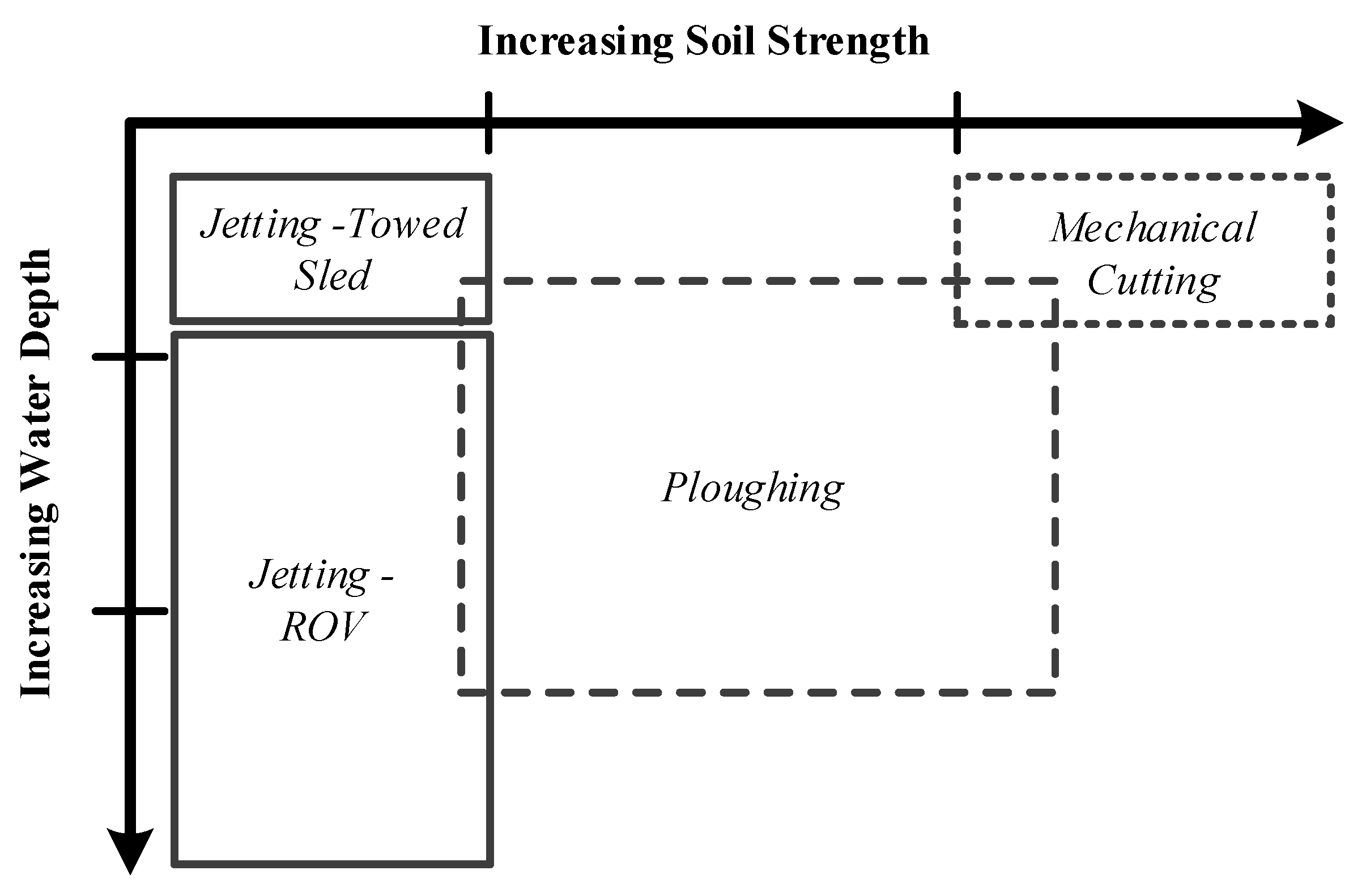
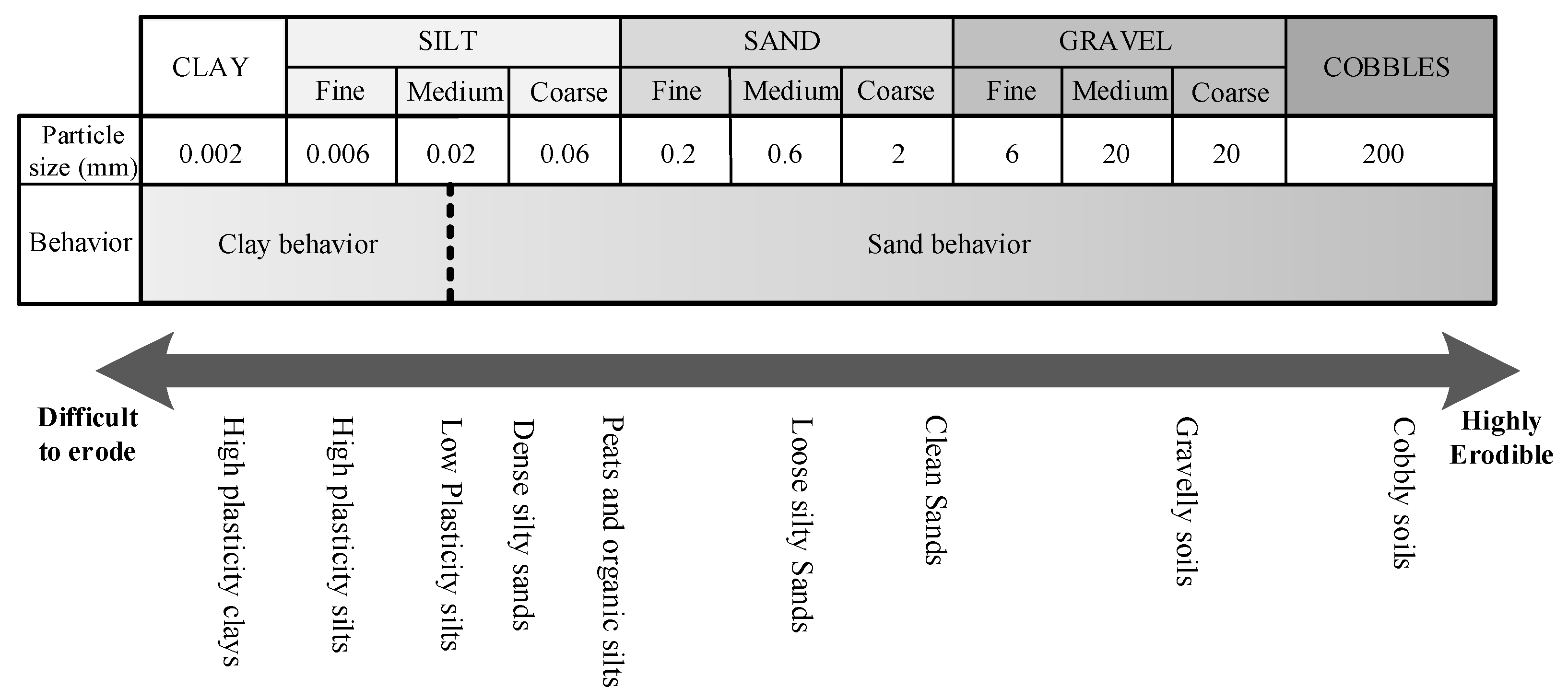
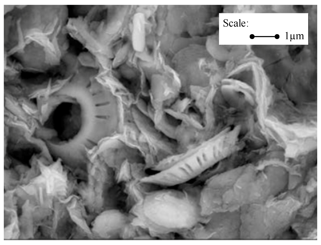
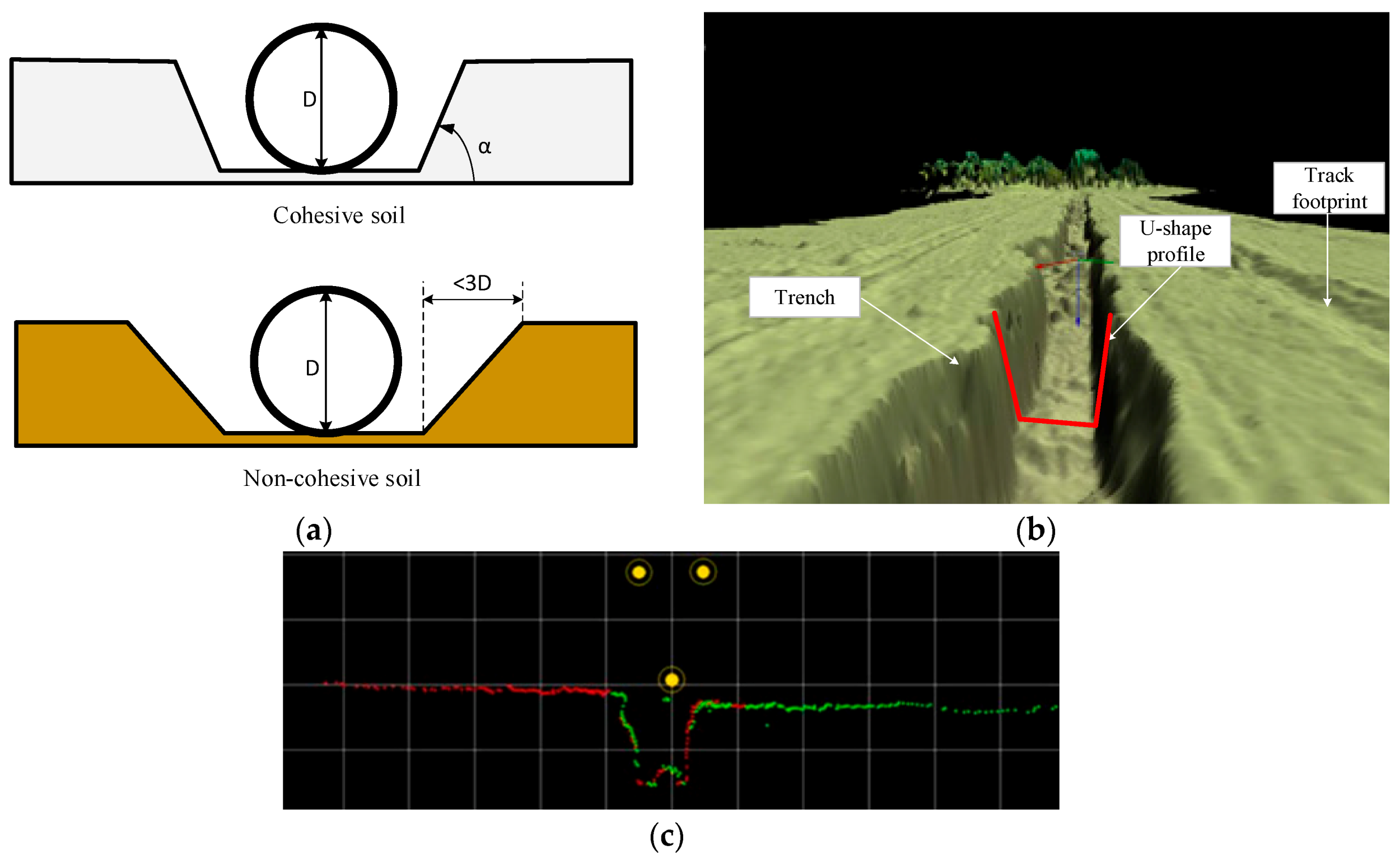
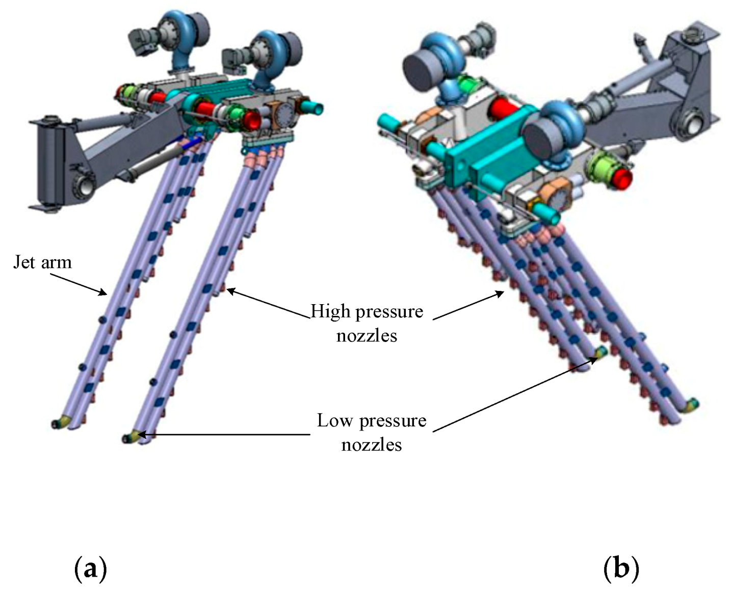