1. Introduction
The principle of operation of the exhaust gas turbocharger is to use the unused kinetic and thermal energy of the ejected engine exhaust. The mostly single-stage turbine is set in rotation by the exhaust gas flowing out and thus drives the compressor. This increases the fluid pressure of the outflowing air which is then pressed into the engine. The increased cylinder filling of the driven engine enables better thermal efficiency during combustion. Turbochargers are also an important part of various systems for reducing emissions from internal combustion engines [
1,
2,
3,
4,
5,
6,
7,
8,
9,
10]. Due to the increased boost pressure of the working medium, either more powerful engines with similar dimensions or similarly powerful engines with significantly smaller dimensions are possible.
In general, particularly high pressure ratios of the compressor blades are required to achieve the required performance increases. The high aerodynamic demands require a very detailed design of blade geometries. Ever thinner blades combined with the low mechanical damping due to the integral construction make the vibration-proof design of turbomachines more difficult. Regardless of the widespread usage of turbomachines, documented damage cases indicate that structural dynamic issues have not been conclusively resolved. Imperfections that already occur during production have a significant influence on the dynamic behaviour of real components. The deviation from the original design is referred to as a “mistuned bladed disc effect” and has been discussed by many researchers in the field of internal combustion engines and aircraft turbine engines [
11,
12,
13,
14]. Researchers [
11,
12] have described a method that allows mistuning distributions to be determined indirectly from vibration measurements without asking about the actual cause of the mistuning.
The largely random mistuning reduces the life of the components that are permanently loaded by centrifugal forces, flow deflection, unsteady pressure fluctuations in the flow and temperature gradients. The purely numerical prediction of the resonance strength is almost impossible for the entire operating range due to the numerous operating points. The vibration safety of a new development is therefore detected in regard to the qualification tests. As a rule, these consist of driving through the operating area of the exhaust gas turbocharger on a combustion chamber or an engine test benches. The measured vibrations of the system are included in the fatigue strength analysis. Considerable safety factors are taken into account. If detailed statements on the real structural behaviour of a design were available at an early stage, the safety factors of some resonance points could be reduced. As a result, designs would be feasible that are closer to the permissible mechanical load limit. Only sound assessments guarantee a solid and resonance-proof turbocharger design.
Knowledge of the real deviation between adjacent blades is necessary for the robust consideration of random mistuning. The parameters can be determined for a single, actually existing rotor using a suitable experimental method. A variety of approaches have now been documented. Some authors [
15,
16] measured the surface of the manufactured blades using white light stripe projection. In doing so, they directly countered the geometric manufacturing tolerance as a presumed cause of the mistuning. Another publication [
17] continued this development and demonstrated good agreement between the properties of optically recorded blades and experimental vibration measurements. Some research studies have also appeared in the field of aircraft and automotive turbochargers [
18,
19], but their results are not very applicable, particularly with regard to the point of identification of the mistuning and the cause of the mistuning of marine engine turbocharger bladed discs.
Further research to identify mistuning has been done mainly in the field of aircraft engines [
20]. This reflects the current trend of applying the integrated structures of blade and disc. Contemporary technology enables this type of structure, which has the advantage of effectively reducing both the weight and the number of engine parts. Contrariwise, there are difficulties with mistuning identification. The reason is that with such a structure, separation of each blade from the disc is not possible, as with the dovetail type blade of conventional compressors. Therefore, it is not possible to know the natural frequency of each blade without disc coupling effect. Some authors dealt with the mistuning problems of small rotors of automotive turbochargers [
21,
22]. One paper [
23] presented the experimental and numerical studies of last-stage low-pressure mistuned steam turbine bladed discs during run-down. The tip-timing method was used to find the mistuned bladed disc modes and frequencies.
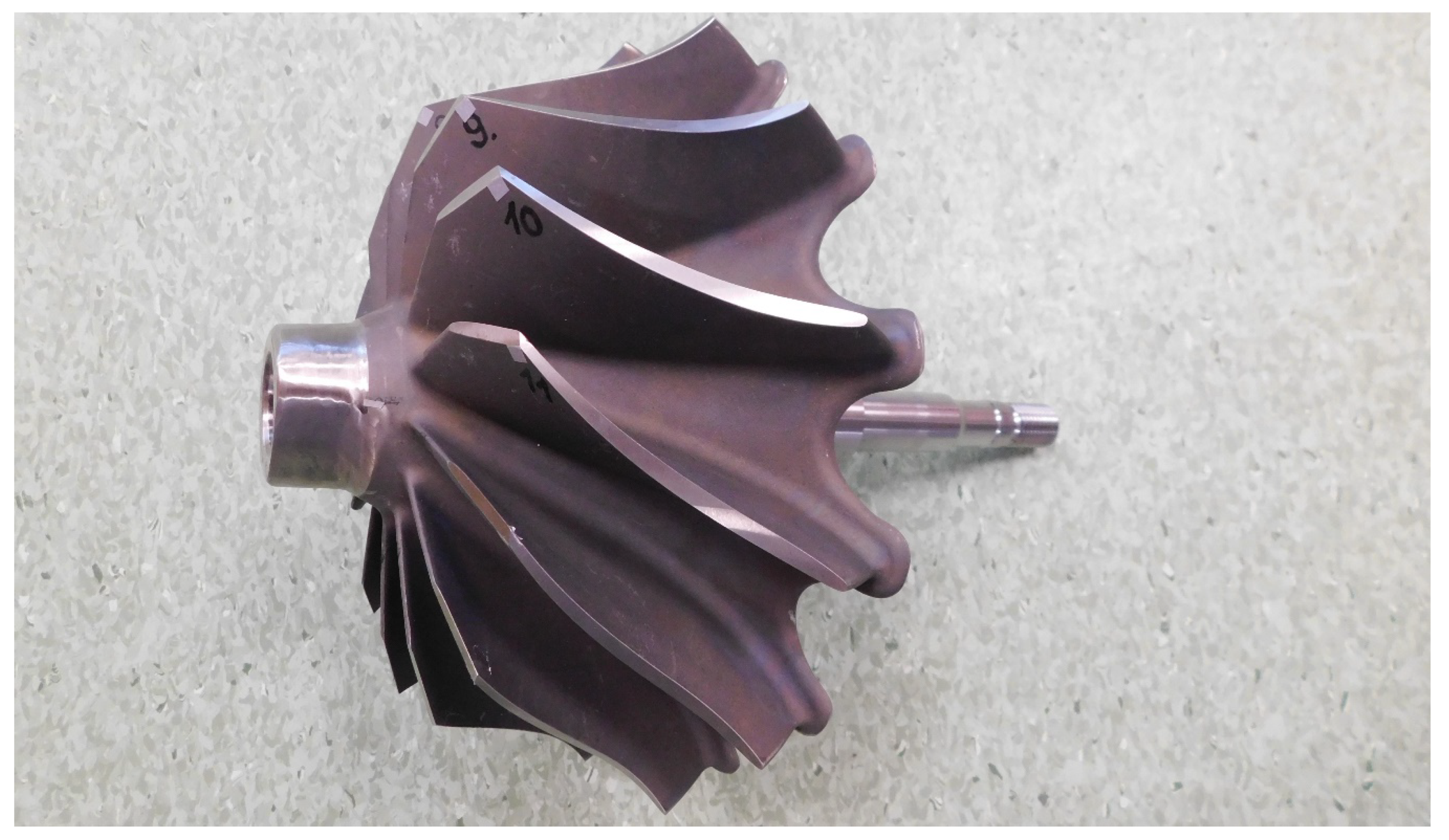
Based on this situation, a marine engine turbocharger rotor was selected as the subject of the research (see
Figure 1). The aim of the solution was to identify mistuning of actually produced turbine rotor of a marine engine turbocharger and to design an effective experimental method for this purpose. Some authors used a laser scanning system to obtain the modal information for different types of mechanical structures [
24,
25,
26,
27]. In this system, a vibration response against the excitation input is obtained at each reference point using a laser Doppler vibrometer. This process is repeated for the same excitation input, the reference point being changed by scanning the laser Doppler vibrometer. After completion of the scan, the frequency response functions obtained for all reference points are correlated and the modal displacement contour of the entire measured surface is created. This procedure requires the application of a very expensive laser scanning technique; moreover, the processing of the measured results is time consuming. Therefore, a procedure was proposed that uses only a simple laser vibrometer and an FE computational model of the turbine rotor.
2. Modelling of Tuned Blade Disc Systems
Modelling using finite elements makes dynamic analysis of complex components considerably easier. The vibration behaviour of turbocharger blade discs can be described by the differential motion equation:
where
M is mass matrix,
R—damping matrix,
K—stiffness matrix,
F—vector of force,
q—vector of generalised coordinates and
t—time in the continuous structure being discretised by a finite number of degrees of freedom. The characteristic values of the natural vibration behaviour are the eigenvalues, i.e., natural frequencies and eigenvectors, i.e., mode shapes. These can be determined by solving the homogeneous and undamped system according to Equation (1). If the vibration behaviour of the bladed disc is to be described as precisely as possible, a very fine discretization may be required. When using FEM, models with several million degrees of freedom are quickly created. Such model sizes are seamlessly manageable currently, but the question of reducing the degrees of freedom of the model arises without losing accuracy in the system description. In addition to classic reduction methods, the exploitation of symmetry properties is essential. With an ideal bladed disc, all sectors are identical, i.e., they have the same mechanical properties, so that no distinction among the stiffness matrices of the individual sectors is required.
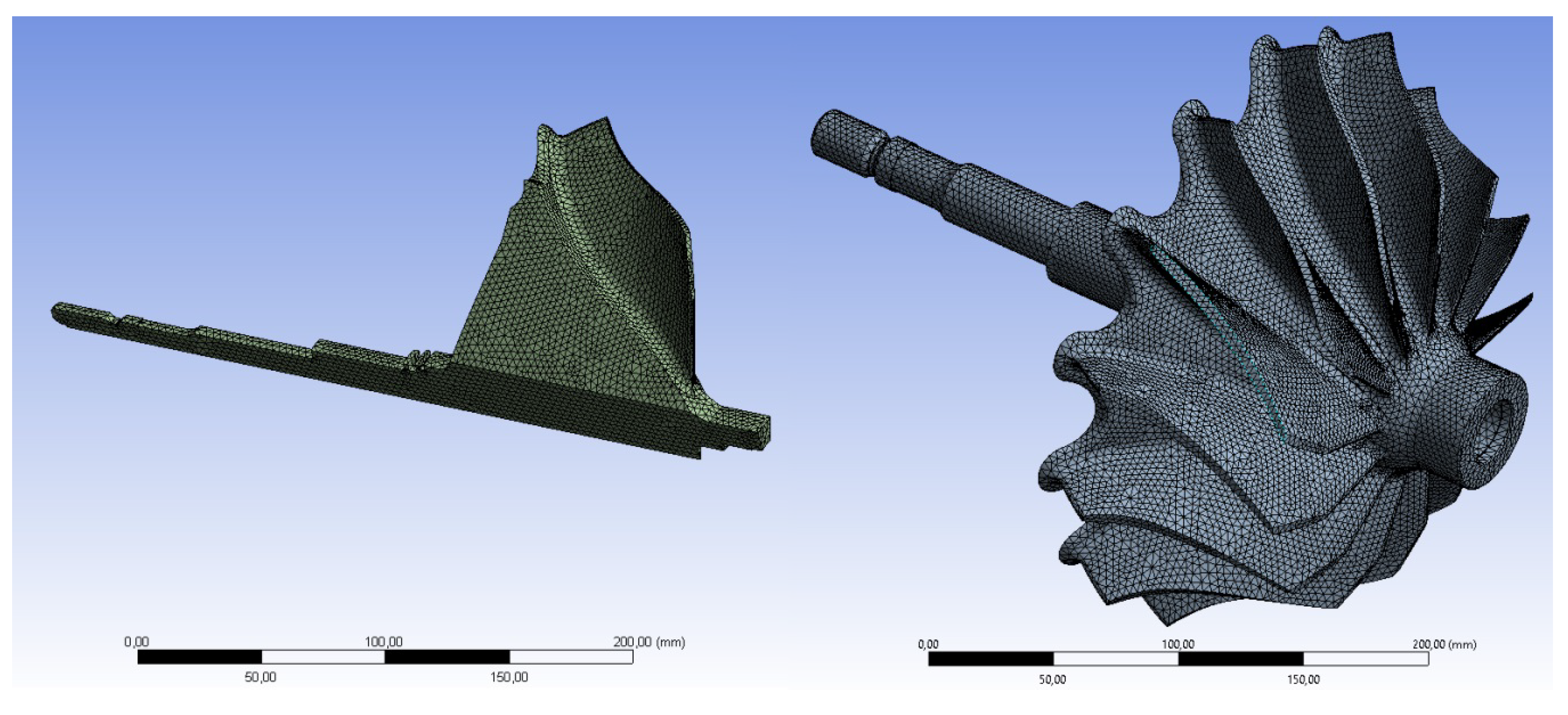
The cyclic symmetry of the blade disc basically allows the analysis to be restricted to one sector without loss of information.
Figure 2 shows one sector of the overall blade disc structure. The element size represents a central setting parameter that has a direct influence on the calculation results. The number of elements increases with an increasing level of model details. This is associated with an increasing number of modes to be calculated, which in turn increase the computational demands. In the case of the radial turbine investigated here, a fine and structured mesh of the blade surface is recommended. The disc body and shaft can be modelled using larger elements. The FE model of the entire turbine blade disc is created by the periodic expansion of the sector and subsequent fusion of the sector boundaries. The FE mesh was created at ANSA software and it had to be done thoroughly in connection with the subsequent creation of a rotation model. There, it is important to properly connect the nodes on both sides of the segment to create the whole rotational cyclic model. At the same time, it is necessary to achieve just the same segments that are really connected correctly. The size of the elements used was carefully optimised by a series of sensitivity analysis.
The turbine rotor is supported in bearings during operation. In modern exhaust gas turbochargers, two plain bearings prevent radial displacements. In addition, a thrust bearing is fitted. The bearing influence plays a negligible role with regard to the blade-dominated vibration forms. In order to achieve the best possible correlation, no boundary conditions are specified for the computational modal analysis.
3. Measurement and Data Processing
3.1. Measurement
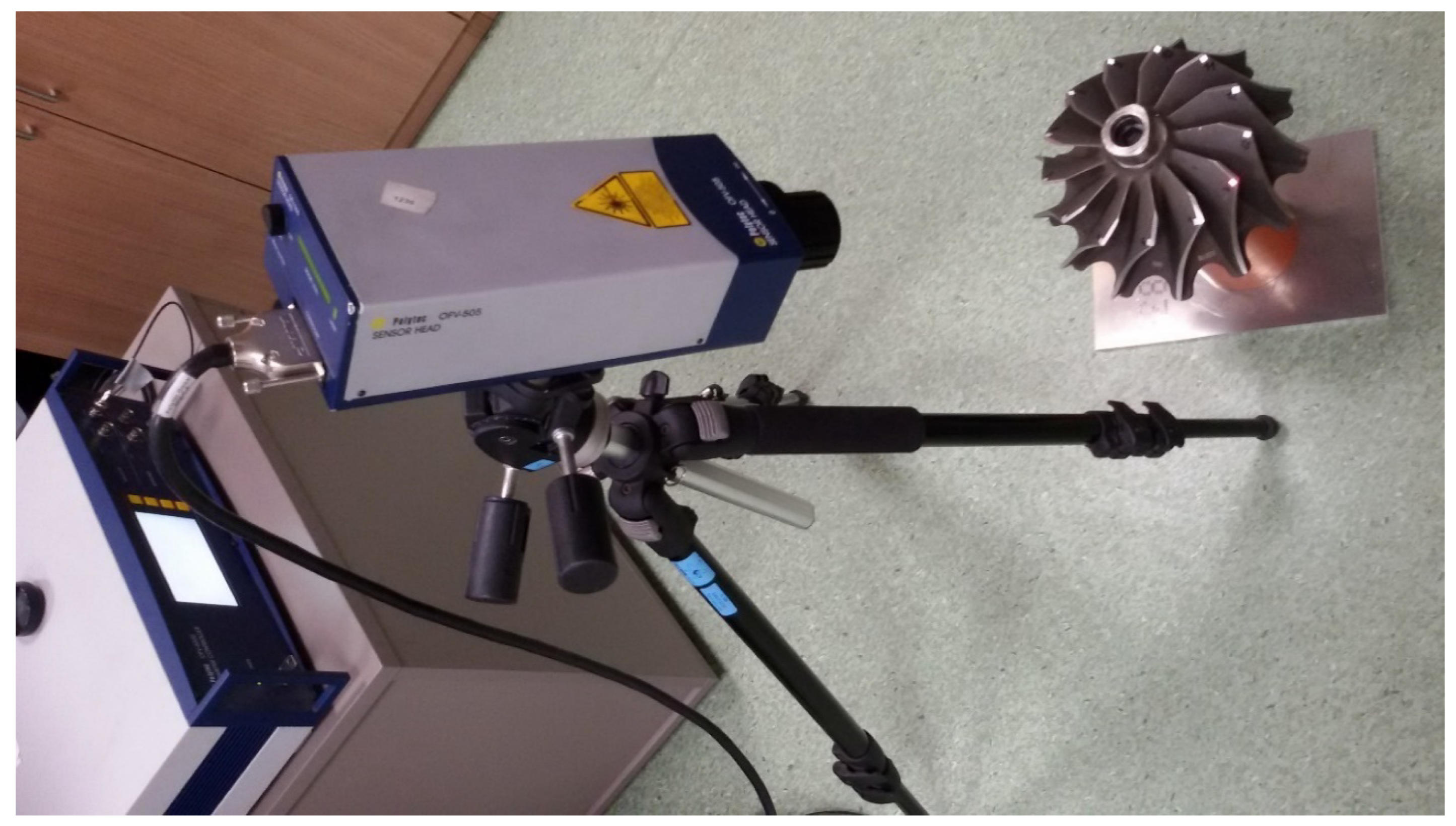
The turbine rotor was mounted on a special highly flexible jig, so that the effect of boundary conditions was negligible. In the sense of a classic modal analysis, a small modal hammer excites the individual rotor blades at a suitable position. A laser Doppler vibrometer measures the blade vibration speeds contactless. As part of the experimental investigation regarding the blade vibrations, only the vibration response of one suitable selected point per blade was measured. This is acceptable if the measurements match the expected mode shapes of the computational model prediction.
The measuring chain was assembled for an experiment from POLYTEC Sensor Head OFV-505, Vibrometer Controller OFV-5000 and cDAQ-9179 with modules NI-9229 and NI-9234. The laser head was positioned 438 mm from the top of the turbocharger blade according to the datasheet (
Figure 3). The beam was directed perpendicularly to the scanning area.
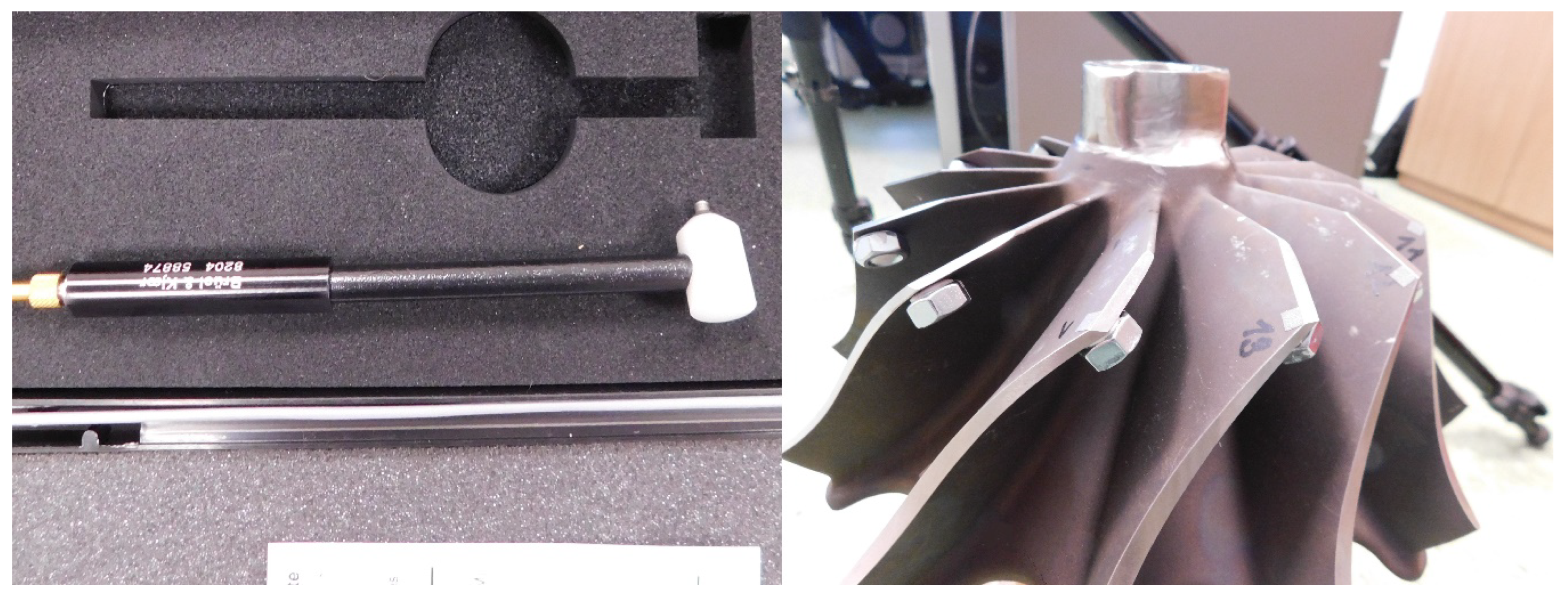
With the individual blade mistuning measurement, the deviation from the mean value of all blades due to the material property or geometry deviations is converted into a calculation value in an experimental way. To decouple the oscillation movement of an individual blade when measuring, all other blades are additionally detuned by attaching additional masses of appropriate size to the blade tips (see
Figure 4 right). The small modal hammer Brüel & Kjær Type 8204 (
Figure 4 left) excites the blade to vibrate, while the laser vibrometer measures the vibration speed at the tip of the blade. Through a suitable choice of size and position of the additional masses as well as through variation of the measuring and excitation point, the mistuning behaviour in the frequency range of the blade dominated mode shapes can be identified. The measurement was carried out without and with additional masses on the blades to make clear their positive effect.
Data monitoring was performed using a programmed script in NI LabVIEW software and 20 second sections were saved. Their data includes at least five responses from the hammer blow to the blade. At the same time, the experiment was checked for a double hammer blow to prevent any adverse effects of the subsequently processed data. Thereafter, five responses lasting 0.2 s and the corresponding time records of the modal hammer force pulses were selected for frequency analysis.
3.2. Data Processing
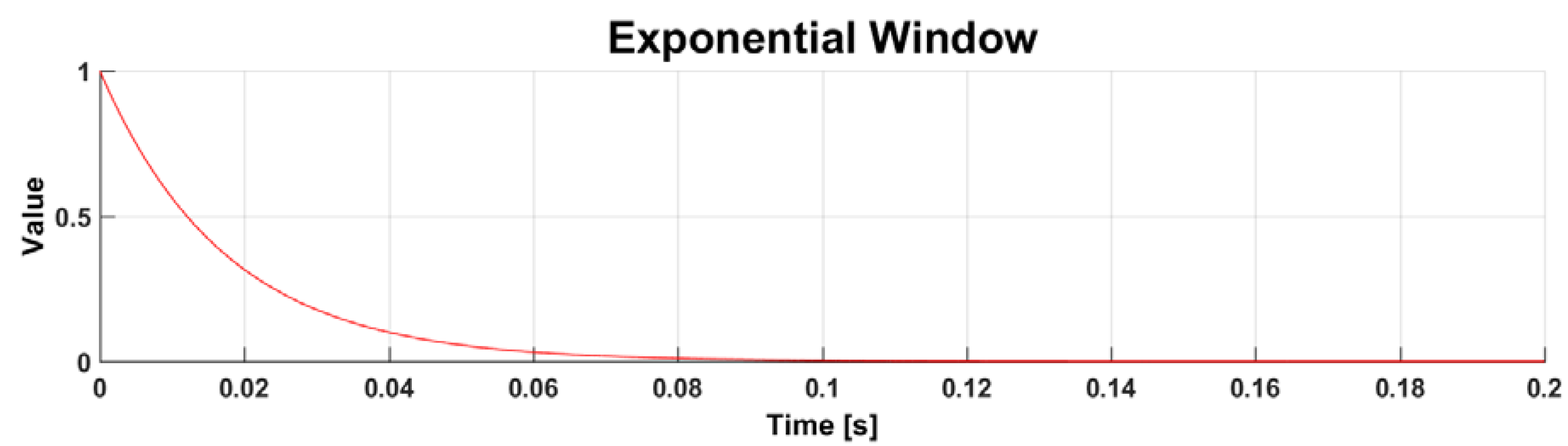
Data processing from the experiment was done using a script in Matlab software. Several main parts were included. The first was the use of an exponential window. Windowing is a common necessary signal processing technique used in modern data acquisition systems [
28,
29]. The exponential window is a time domain weighting function that has been elaborated for use with transient-type signals, such as those of impact testing. Used correctly, the exponential window can minimise leakage errors on lightly damped signals and can also improve the signal-to-noise ratio. The effect of the exponential window (
Figure 5) is to increase the apparent damping of the measured system. The exponential window [
30] is an exponential function as defined in equation (2) where the parameter
f is the last point value of the window,
n is the number of samples and
i is index of the exponential function:
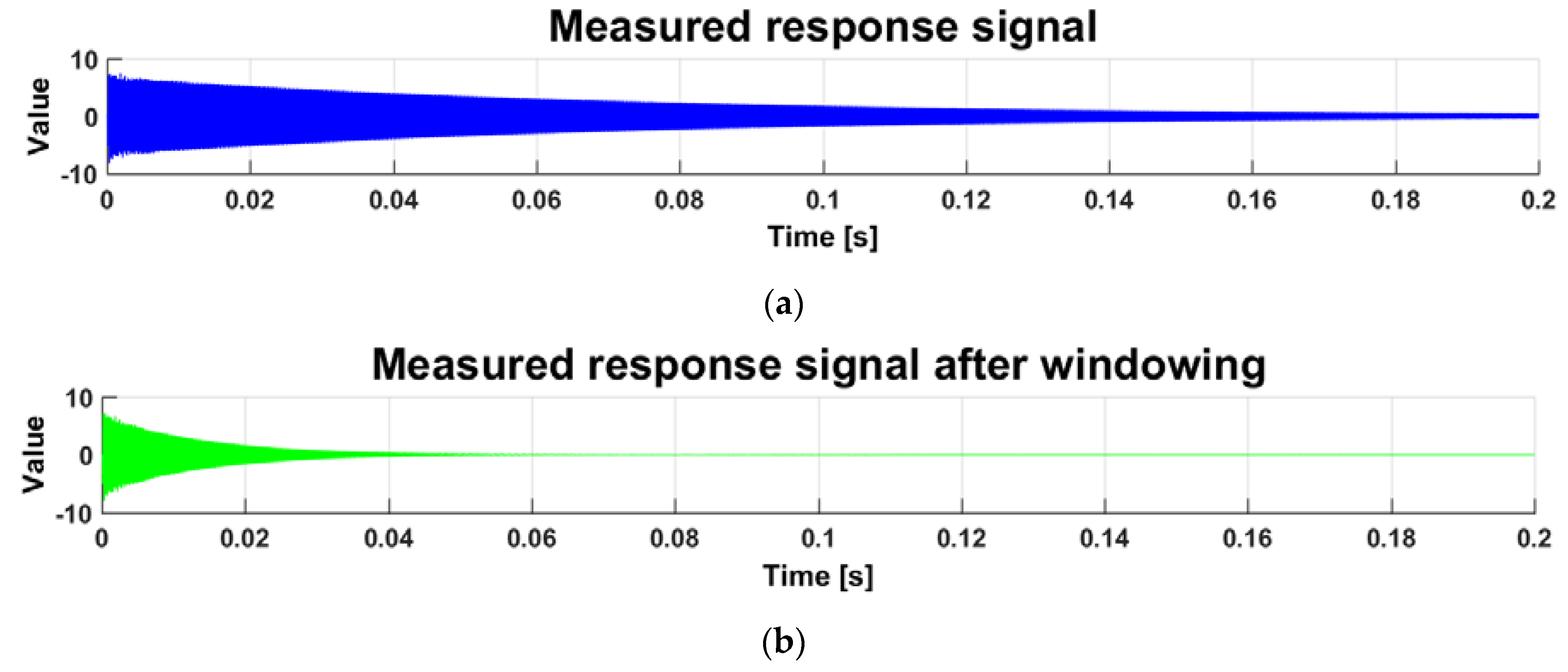
The time variable for the exponential function starts at zero, regardless if a pretrigger delay is used in the data acquisition. When impact testing lightly damped blade structures, the purpose of the exponential window is to reduce the effects of leakage by forcing the data to meet the requirements of a completely observed transient response signal more closely. By definition, a fully observed transient signal must begin and end within the measured time record. For lightly damped blade systems, the response of the structure will typically continue beyond the time period of data collection as shown in
Figure 6a. Since the response does not decay to near zero at the end of the time record, the exponential window is applied to reduce the signal at the end of the time record to approximately 1%. The signal according to
Figure 6a after the window has been applied shows
Figure 6b. The windowed signal more closely represents an observable transient.
This data was processed by a fast Fourier transform (FFT) algorithm in a complex form to evaluate the transfer function of the system. That is, the FFT analysis was performed for the impact force course and its corresponding measured response. Subsequently, the ratio of the output to the input of the system was used to obtain the transfer function:
where
FFTout is the resulting FFT analysis complex vector from the response data and
FFTforce is the resulting FFT analysis complex vector from the force pulse data. The calculation works using complex arithmetic. The measurement of each turbocharger blade was performed five times to reduce possible measurement errors, and these five measurements were included in the data processing, at the end of which five calculated FFT spectra were always averaged. Since the time window was 0.2 s, the frequency resolution of the FFT is 5 Hz, and thus, the uncertainty of determination of each spectral component is 2.5 Hz, which is completely satisfactory for the determination of the blade disc mistuning.
4. Results and Discussion
4.1. Finite Elements Method
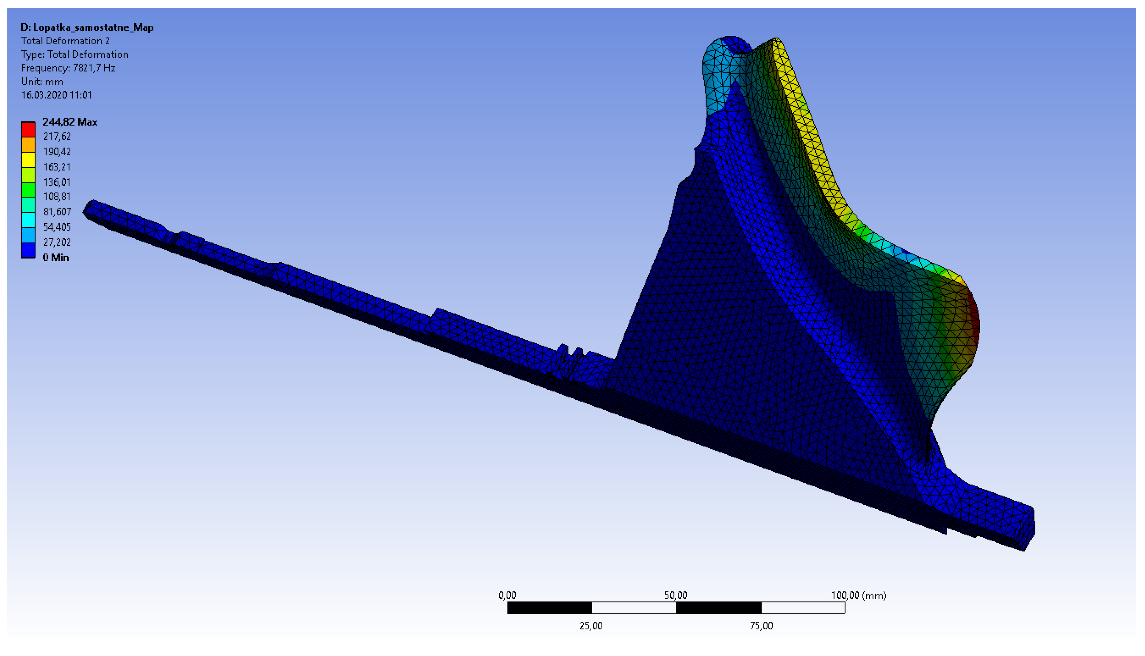
Modal analysis of one turbocharger turbine segment was performed using FEM, as shown in
Figure 7. Boundary conditions with zero displacement and rotation in all directions were applied to the sides of the segment. Thus, the natural frequencies associated with the turbocharger blade were obtained. In this way, the mode shapes were obtained.
Figure 7 shows mode 2 for illustration.
The calculated natural frequencies of the blade are presented in
Table 1. The interest in the frequency range was up to 20,000 Hz, where the first seven modes are located. The calculated natural frequencies show approximate natural frequency values of the blade-dominant mode shapes of the rotational symmetric turbine disc.
Subsequent forms of mesh models were used in the next step (
Figure 2). The second analysis was performed from one segment as a rotational cyclic modal analysis. It results in a nodal diameter map of the tuned turbine rotor. However, this is not the main subject of this article.
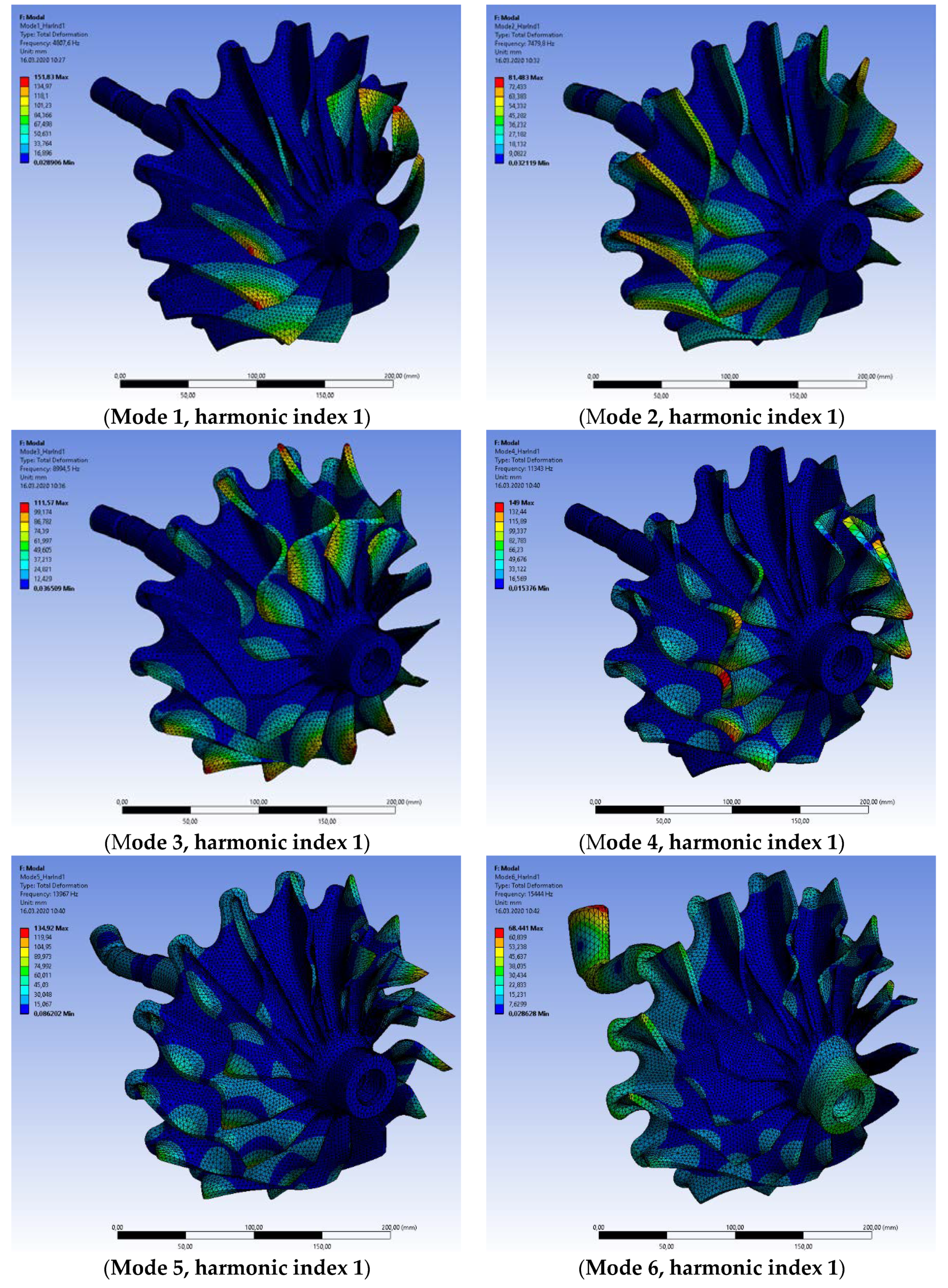
Subsequently, a third FE model was created from a rotated model of one segment. The modal properties of this three-dimensional (3D) turbine FE model are identical to the previous rotational cyclic model. This model will further serve for analyses with different material properties of the blades and for analysing the mistuning effect. An example of the blade-dominated mode shapes for modes 1–6 is shown in
Figure 8.
The material properties have been the same thus far for all segments to verify the following measurement results and possibly debug the model. The mistuned 3D model will be used for research of dangerous stress concentrators due to different characteristics of the individual blades.
4.2. Measuremet
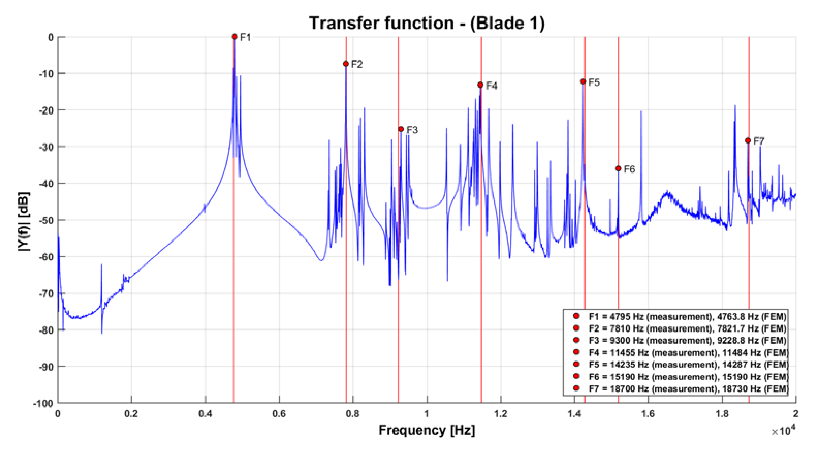
The transfer functions of the individual blades were obtained by the measurements using subsequent the mathematical procedure according to Equation 3. The resulting transfer function of the first blade is shown in
Figure 9. In this case, no additional masses on other blade tips were used. Therefore, this figure is shown here to illustrate the difference from the resulting transfer function in
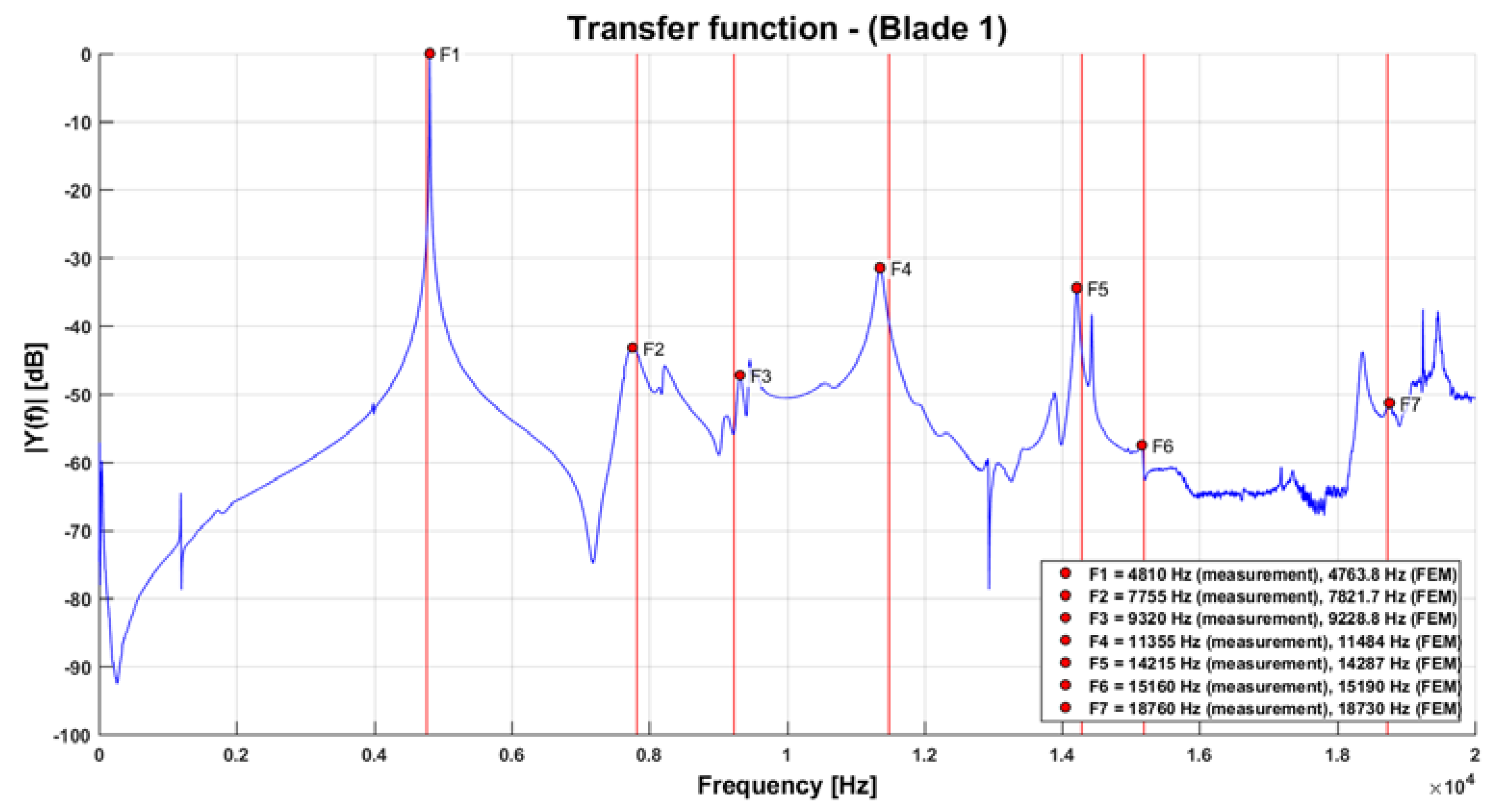
Figure 10 showing the measurement variant when placing additional masses on other blades.
This method is very effective in suppressing the influence of the slightly different natural frequencies of the unmeasured blades and makes it possible to obtain the natural frequencies of individual blades of a real turbine wheel and to create a mistuned 3D model for further detailed dynamic analyses.
In
Figure 10, red lines are visible to symbolise the natural frequencies of the turbocharger turbine blade from the FE simulation. Compliance with the measurement is very good and it is obvious that the method using FE model is well prepared for further utilization with much simpler demands than using expensive 3D scanning laser. Furthermore, applying this method, the user can concentrate on the natural blade dominant frequencies only, without having to deal with other spectrum peaks that belong entirely or predominantly to the turbine bladed disc.
5. Conclusions
In the present article, the vibration characteristics of a radial turbine bladed disc of a marine engine turbocharger were investigated. Starting with the analysis of structural dynamic properties of cyclic symmetry components, basic procedures were transferred to special problems of bladed discs of marine turbocharger radial turbines and expanded. In particular, the assignment of individual peaks in the measured transmission functions to the corresponding mode shapes was performed using a carefully designed FE model, without the need to apply an expensive scanning vibrometer. In addition, the distribution of the strain energy between the disc and the blade calculated by the FE model is a next parameter that allows the systematic assessment each of the large number of modal shapes present in this complicated structure. The mode shapes with predominant strain energy in the blade are thus referred to as blade-dominated. Depending on the criterion of distribution of the strain energy among the blades and the disc, some modes can be called mixed. The transfer functions shown above also record these mixed modes such as matching peaks, but their effect on blade stress is not significant. Disc dominant modes do not occur in the examined frequency range of the analysed marine engine turbocharger radial turbine. The reason for this is the massive disc and the rigid connection of the blades to them.
Based on the results of the measurements described above, it was possible to create a 3D mistuned FE model of the turbine bladed disc. Creation of this model is based on individual adaptation of the modulus of elasticity to individual blades using optimization algorithms. The vibration behaviour of the real bladed discs can be achieved with sufficient accuracy by such 3D models, unlike methods that are based on the use of substructures and do not describe the frequency splitting due to mistuning with the necessary accuracy. Since the description of the optimization algorithm and the creation of the 3D model of the mistuned turbine wheel would go far beyond the possible size of this article, this topic will be the subject of a separate publication.
With regard to industrial application, it should be noted that an improvement in manufacturing accuracy is only conditionally recommended, since increasing the manufacturing accuracy of the blades would entail unacceptable financial costs. Rather, it is important to determine the inclination of individual vibration modes in order to tend large increases in stress. It should be noted that large stress increases are always accompanied by strongly localised modes. However, strongly localised mode shapes can only occur if the tuned bladed disc system has a sufficient number of node diameter vibrations in a relative frequency proximity. These cases can be identified already in the early stages of development if a suitable FE blade disc model is used. Together with the described effective mistuning identification method of integrated bladed discs, the development of new marine engine turbochargers can be significantly accelerated. Another added value of the method is the possibility of its relatively easy automation, both in terms of measurement and its subsequent processing and evaluation. The turbocharger manufacturer can thus obtain complete statistical information on the parameters of the blade discs in relation to the mistuning caused by various influences in the production process.
Author Contributions
Conceptualization, V.P.; methodology, V.P. and P.K.; software, P.K. and O.F.; validation, P.K. and A.L.; writing—review and editing, V.P. and P.K. All authors have read and agreed to the published version of the manuscript.
Funding
The authors gratefully acknowledge funding from the Specific research on BUT FSI-S-20-6267.
Acknowledgments
The authors thank the Brno University of Technology for support.
Conflicts of Interest
The authors declare no conflict of interest.
References
- DieselNet. Emission Standards: EU: Cars and Light Trucks. Available online: https://dieselnet.com/standards/eu/ld.php (accessed on 17 March 2020).
- DieselNet. Emission Standards: EU: Heavy-Duty Truck and Bus Engines. Available online: https://dieselnet.com/standards/eu/hd.php (accessed on 17 March 2020).
- European Committee for Standardization. Automotive Fuels—Diesel—Requirements and Test Methods, EN 590:2009. Available online: http://www.envirochem.hu/www.envirochem.hu/documents/EN_590_2009_hhV05.pdf (accessed on 17 March 2020).
- International Organization for Standardization, ISO 8217:2017. Available online: https://www.iso.org/standard/64247.html (accessed on 17 March 2020).
- Murakami, M.; Tanaka, H.; Fukuyama, M.; Fujibayashi, T.; Okazaki, S.; Shibata, J.; Tanaka, H.; Hiraiwa, S.; Kobayashi, R.; Ezu, Y. Development of marine SCR system (separate type) for large two-stroke diesel engines. Hitz Tech. Rev. 2014, 75, 2–9. (In Japanese) [Google Scholar]
- Winebrake, J.J.; Corbett, J.J.; Green, E.H.; Lauer, A.; Eyring, V. Mitigating the health impacts of pollution from oceangoing shipping: An assessment of low-sulfur fuel mandates. Environ. Sci. Technol. 2009, 43, 4776–4782. [Google Scholar] [CrossRef] [PubMed] [Green Version]
- Okubo, M.; Kuwahara, T.; Yoshida, K.; Kawai, M.; Hanamoto, K.; Sato, K.; Kuroki, T. Total marine diesel emission control technology using nonthermal plasma hybrid Process. In Proceedings of the 27th CIMAC World Congress on Combustion Engine Technology, Shanghai, China, 13–16 May 2013; Paper No.153. p. 14. [Google Scholar]
- Herdzik, J. Emissions from marine engines versus IMO certification and requirements of tier 3. J. Kones Powertrain Transp. 2011, 18, 161–167. [Google Scholar]
- Puškár, M.; Brestovič, T.; Jasminská, N. Numerical simulation and experimental analysis of acoustic wave influences on brake mean effective pressure in thrust-ejector inlet pipe of combustion engine. Int. J. Veh. Des. 2015, 67, 63–76. [Google Scholar] [CrossRef]
- Sinay, J.; Puškár, M.; Kopas, M. Reduction of the NOx emissions in vehicle diesel engine in order to fulfill future rules concerning emissions released into air. Sci. Total Environ. 2018, 624, 1421–1428. [Google Scholar] [CrossRef] [PubMed]
- Feiner, D.M.; Griffin, J.H. Mistuning identification of bladed disks using a fundamental mistuning model—Part I: Theory. J. Turbomach. 2004, 132, 150–158. [Google Scholar] [CrossRef]
- Feiner, D.M.; Griffin, J.H. Mistuning Identification of bladed disks using a fundamental mistuning model—Part II: Application. J. Turbomach. 2004, 126, 159–165. [Google Scholar] [CrossRef]
- Giersch, T.; Beirow, B.; Popig, F.; Kühhorn, A. FSI-based forced response analyses of a mistuned high pressure compressor blisk. In Proceedings of the 10th International Conference on Vibration in Rotating Machinery, London, UK, 11–13 September 2012. [Google Scholar]
- Giersch, T.; Hönisch, P.; Beirow, B. Arnold kühhorn forced response analyses of mistuned radial inflow turbines. J. Turbomach. 2013, 135, 9. [Google Scholar] [CrossRef]
- Schoenenborn, H.; Grossmann, D.; Satzger, W.; Zisik, H. Determination of blade-alone frequencies of a blisk for mistuning analysis based on optical measurements. In Proceedings of the ASME Turbo Expo, Orlando, FL, USA, 8 June 2009; pp. 221–229. [Google Scholar]
- Schoenenborn, H.; Junge, M.; Retze, U. Contribution to free and forced vibration analysis of an intentionally mistuned blisk. In Proceedings of the ASME Turbo Expo, Munich, Germany, 11 June 2012; pp. 1111–1120. [Google Scholar]
- Maywald, T. Modellierung und Simulation Integral Gefertigter Verdichterlaufräder auf der Grundlage einer Dreidimensionale Oberflächenvermessung. Ph.D. Thesis, Brandenburgische Technische Universität Cottbus – Senftenberg, Cottbus, German, 2018. [Google Scholar]
- Giersch, T.; Figaschewsky, F.; Hönisch, P.; Kühhorn, A.; Schrape, S. Numerical Analysis and validation of the rotor blade vibration response induced by high pressure compressor deep surge. In Proceedings of the ASME Turbo Expo 2014: Turbine Technical Conference and Exposition, Düsseldorf, Germany, 16–20 June 2014; pp. 1–12. [Google Scholar]
- Nguyen-Schäfer, H. Rotordynamics of Automotive Turbochargers; Springer: Berlin/Heidelberg, Germany, 2012. [Google Scholar]
- Figaschewsky, F.; Kühhorn, A.; Beirow, B.; Nipkau, J.; Giersch, T.; Power, B. Design and analysis of an intentional mistuning experiment reducing flutter susceptibility and minimizing forced response of a jet engine fan. In Proceedings of the ASME Turbo Expo 2017: Turbomachinery Technical Conference and Exposition, Charlotte, CA, USA, 26–30 June 2017; pp. 1–13. [Google Scholar]
- Kulkarni, A.; Larue, G. Vibratory response characterization of a radial turbine wheel for automotive turbocharger application. In Proceedings of the ASME Turbo Expo 2008: Power for Land, Sea, and Air, Berlin, Germany, 9–13 June 2008; pp. 583–591. [Google Scholar]
- Hemberger, D.; Filsinger, D.; Bauer, H.-J. Mistuning modeling and its validation for small turbine wheels. In Proceedings of the ASME Turbo Expo 2013: Turbine Technical Conference and Exposition, San Antonio, TX, USA, 3–7 June 2013; pp. 1–11. [Google Scholar]
- Rzadkowski, R.; Kubitz, L.; Maziarz, M.; Troka, P.; Dominiczak, K.; Szczepanik, R. Tip-Timing measurements and numerical analysis of last-stage steam turbine mistuned bladed disc during run-down. J. Vib. Eng. Technol. 2020, 8, 409–415. [Google Scholar] [CrossRef] [Green Version]
- Hattori, H. Study on mistuning identification of vehicle turbocharger turbine BLISK. In Proceedings of the ASME Turbo Expo 2014: Turbine Technical Conference and Exposition, Düsseldorf, Germany, 16–20 June 2014; pp. 1–10. [Google Scholar]
- Drápal, L.; Šopík, L. Influence of crankshaft counterweights upon engine block load. In Proceedings of the 20th International Scientific Conference Transport Means, Juodkranté, Lithuania, 5–7 October 2016; pp. 809–814. [Google Scholar]
- Prokop, A.; Řehák, K. Virtual prototype application to heavy-duty vehicle gearbox concept. In Proceedings of the Engineering Mechanics 2017, Svratka, Czech Republic, 15–18 May 2017; pp. 810–813. [Google Scholar]
- Zeizinger, L.; Pokorný, P. The consequence of using orthotropic material in a mechanical system. Vibroengineering Procedia 2018, 18, 128–131. [Google Scholar] [CrossRef]
- Tůma, J.; Kočí, P. Calculation of a shock response spectrum. In Proceedings of the 12th International Carpathian Control Conference (ICCC), Velke Karlovice, Czech Republic, 25–28 May 2011; pp. 408–413. [Google Scholar]
- Tůma, J.; Kočí, P. Calculation of a shock response spectrum. In Proceedings of the Colloquium Dynamics of Machines 2009, Prague, Czech Republic, 3–4 February 2009; pp. 408–413. [Google Scholar]
- National Instruments, Exponential Window VI. Available online: https://zone.ni.com/reference/en-XX/help/371361R-01/lvanls/exponential_window/ (accessed on 17 March 2020).
© 2020 by the authors. Licensee MDPI, Basel, Switzerland. This article is an open access article distributed under the terms and conditions of the Creative Commons Attribution (CC BY) license (http://creativecommons.org/licenses/by/4.0/).


