Anti-Explosion Performance of Composite Blast Wall with an Auxetic Re-Entrant Honeycomb Core for Offshore Platforms

Abstract
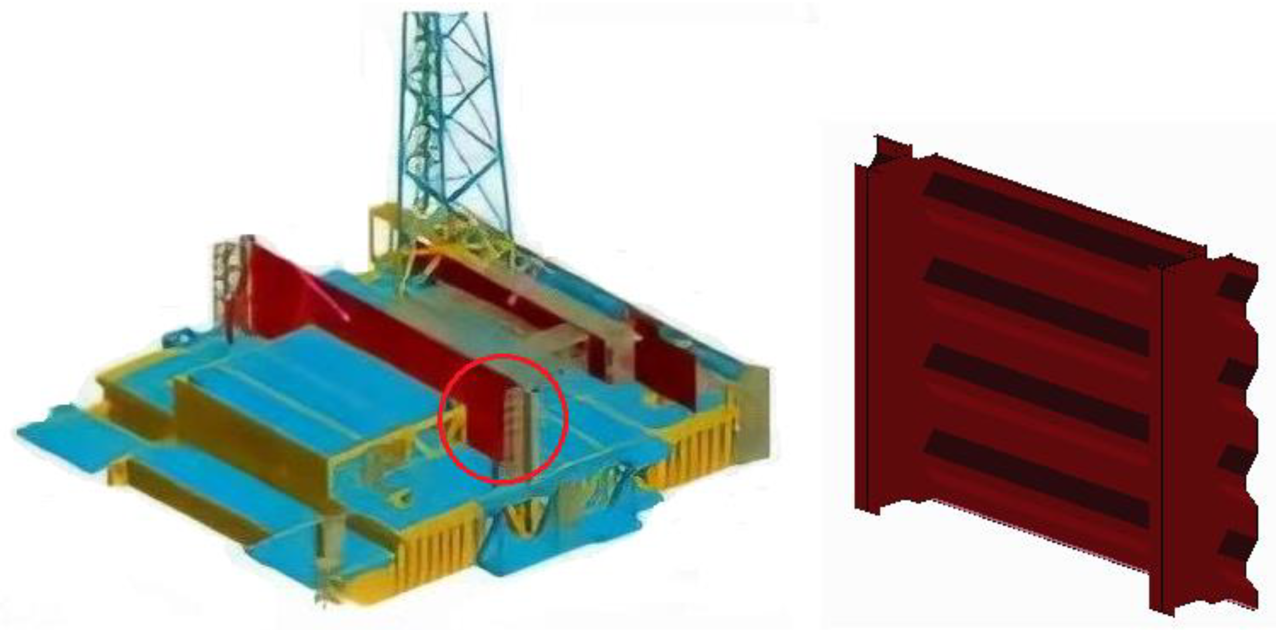
:1. The State-of-the-Art Blast Wall Design in Offshore Platforms
2. Schematic Design of ARBW, HSBW and CBW
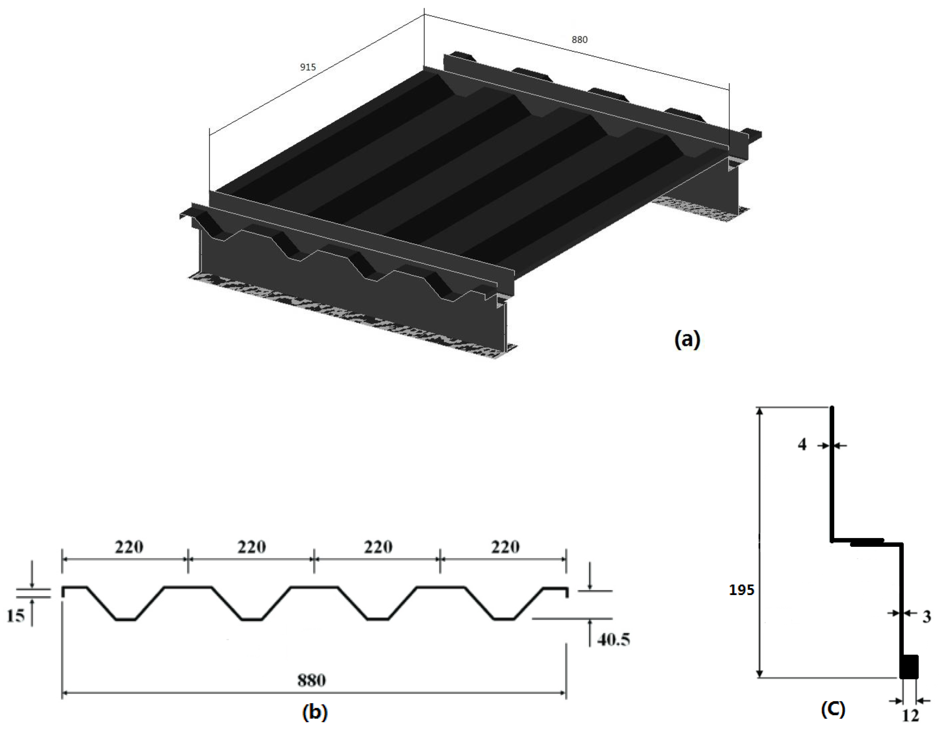
2.1. Design of CBW
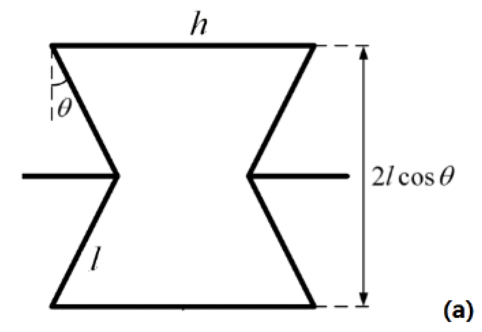
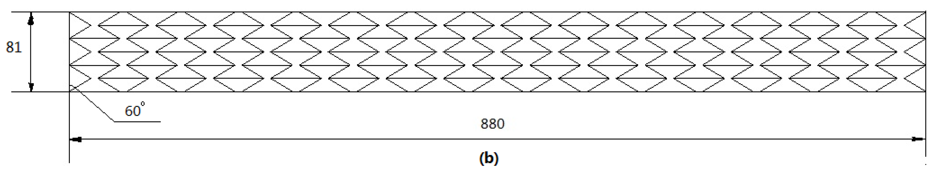
2.2. Design Descriptions of ARBW and HSBW
2.3. Model Diagrams of ARBW and HSBW
3. Numerical Models of Anti-Explosion Analysis for the Proposed Blast Wall
3.1. Material Model
3.2. Finite Element Model
3.3. Loadings and Constraints
4. Comparative Analysis of Anti-Explosion Performance
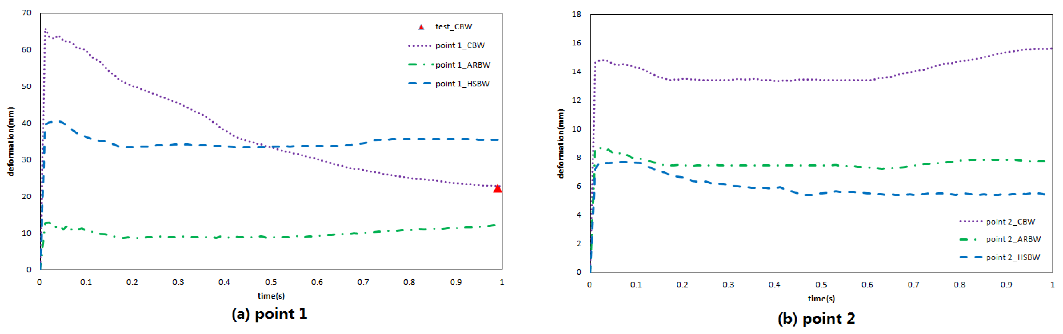
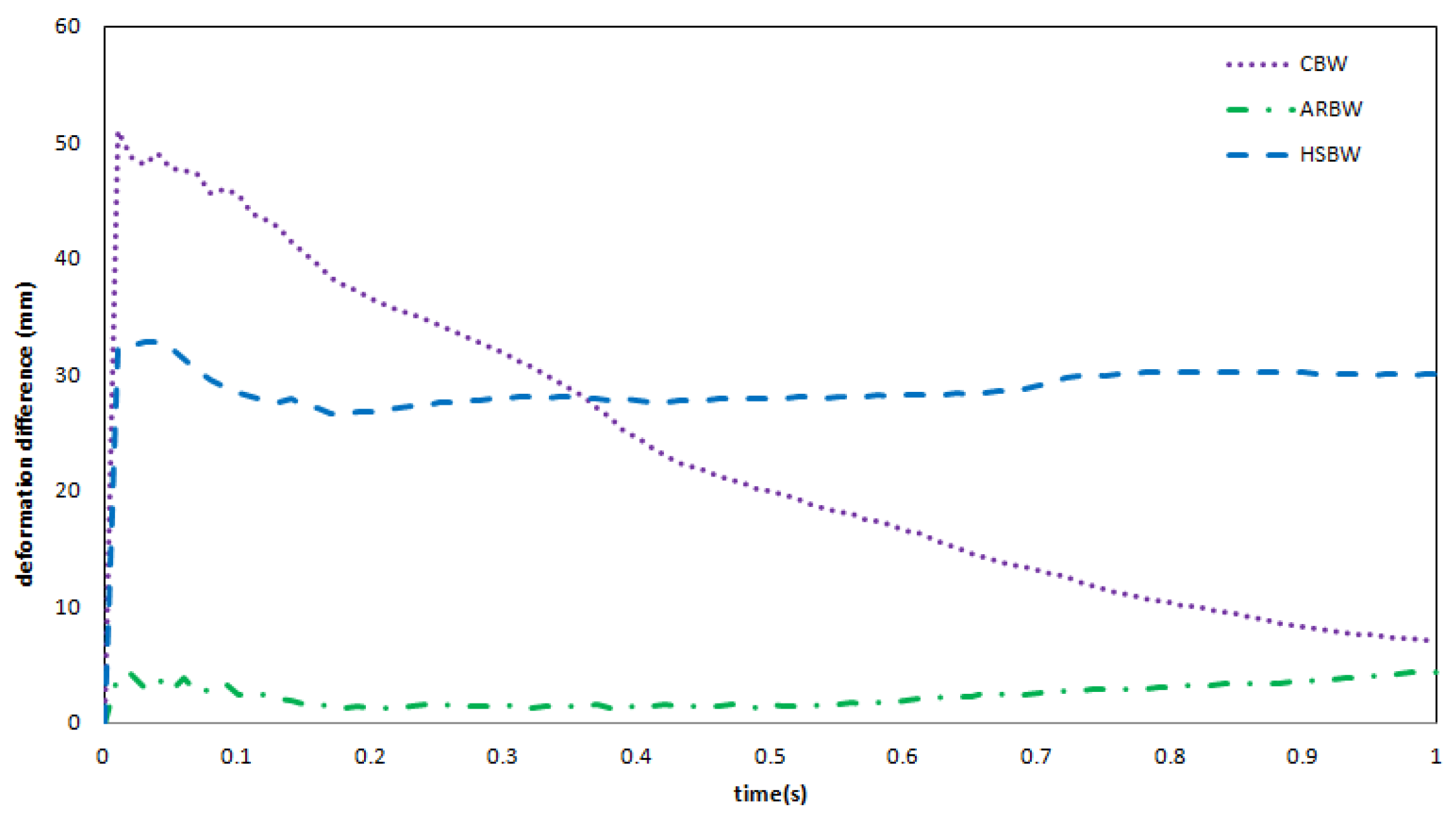
4.1. Deformation
4.2. Resistance Performance Evaluation
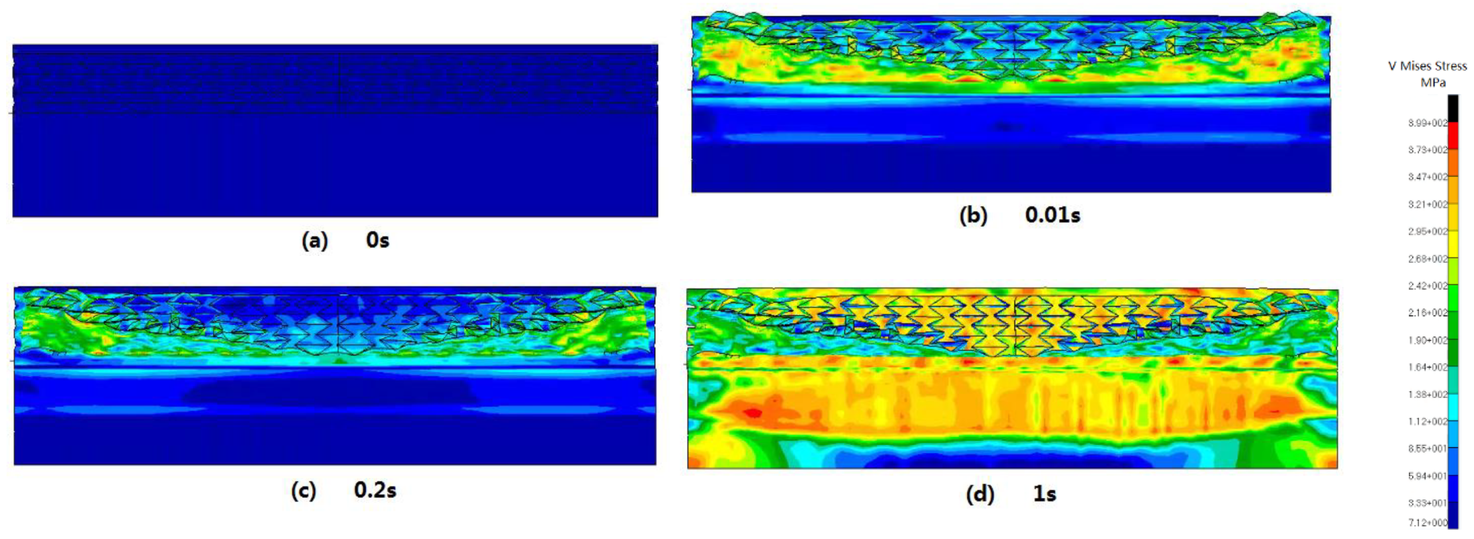
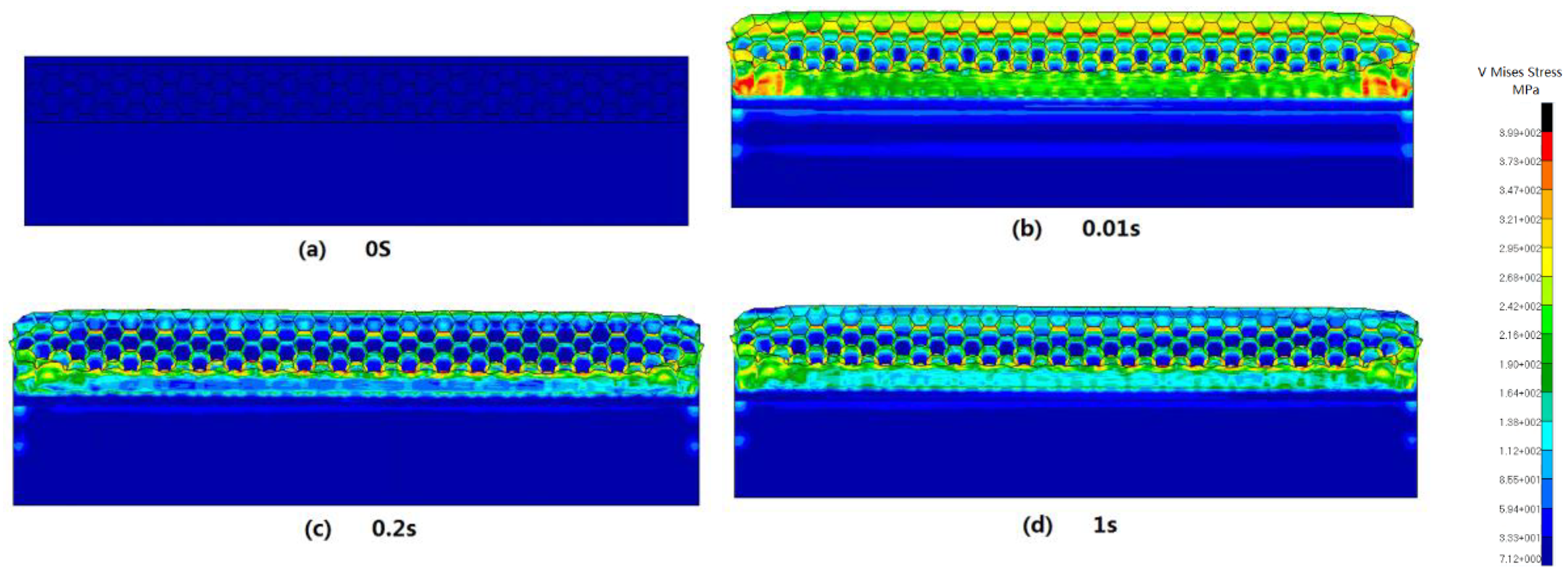
4.3. Stress Distribution
4.4. Failure Mechanism
5. Conclusions
- ●
- For the ARBW and the HSBW, the distributed impulse loading was absorbed through panel deformation. The ARBW works with crushable cells with auxetic behavior, which the HSBW achieves through whole panel bending.
- ●
- To measure the anti-explosion performance, the deformation difference can be used for the HSBW and the CBW, but this hardly works for the ARBW. The stress diagram of the ARBW can demonstrate energy absorption and redistribution because of the auxetic mechanism.
- ●
- As regards the deformation of point 2, both the ARBW and the HSBW protected the connection well. With regard to the stress of the connection, the HSBW performed better. Concerning point 1, the ARBW provided the best anti-explosion performance.
- ●
- The cell-collapsed edge of ARBW was strengthened due to the densification effect. The plastic failure of CBW happened at the connection first, which meant that the connection absorbed shock energy and partially failed.
Author Contributions
Funding
Conflicts of Interest
References
- Syed, Z.I.; Mohamed, O.A.; Rahman, S.A. Non-linear Finite Element Analysis of Offshore Stainless Steel Blast Wall under High Impulsive Pressure Loads. Procedia Eng. 2016, 145, 1275–1282. [Google Scholar] [CrossRef] [Green Version]
- Summerhayes, C. Deep Water—The Gulf Oil Disaster and the Future of Offshore Drilling. Underw. Technol. 2011, 30, 113–115. [Google Scholar] [CrossRef]
- Brewerton, R. Design Guide for Stainless Steel Blast Wall, Technical Note 5; Fire and Blast Information Group: London, UK, 1999. [Google Scholar]
- Walker, S.; Bleach, R.; Carney, S.; Fairlie, G.; Louca, L.A. New guidance on the design of offshore structures to resist the explosion hazard. In Proceedings of the OMAE03, Cancun, Mexico, 8–13 June 2003. [Google Scholar]
- Paik, J. Design of offshore facilities to resist gas explosion hazard, engineering handbook. Ships Offshore Struct. 2006, 1, 165–169. [Google Scholar] [CrossRef]
- Boh, J.W.; Louca, L.A.; Choo, Y.S. Energy absorbing passive impact barrier for profiled blastwalls. Int. J. Impact Eng. 2005, 31, 976–995. [Google Scholar] [CrossRef]
- Nwankwo, E.; Fallah, A.S.; Langdon, G.S.; Louca, L.A. Inelastic deformation and failure of partially strengthened profiled blast walls. Eng. Struct. 2013, 46, 671–686. [Google Scholar] [CrossRef]
- Christian, W.; Kim, B.T. Behaviors of a Blast Wall According to the Angle of Vee Stiffener. Appl. Mech. Mater. 2012, 152, 856–859. [Google Scholar]
- Dharmasena, K.P.; Wadley, H.N.G.; Xue, Z.; Hutchinson, J.W. Mechanical response of metallic honeycomb sandwich panel structures to high-intensity dynamic loading. Int. J. Impact Eng. 2008, 35, 1063–1074. [Google Scholar] [CrossRef]
- Theobald, M.D.; Langdon, G.S.; Nurick, G.N.; Pillay, S.; Heyns, A.; Merrett, R.P. Large inelastic response of unbonded metallic foam and honeycomb core sandwich panels to blast loading. Compos. Struct. 2010, 92, 2465–2475. [Google Scholar] [CrossRef]
- Zhu, F.; Zhao, L.M.; Lu, G.X. A numerical simulation of the blast impact of square metallic sandwich panels. Int. J. Impact Eng. 2009, 36, 687–699. [Google Scholar] [CrossRef]
- Pydah, A.; Batra, R.C. Blast loading of bumper shielded hybrid two-core Miura-ori/honeycomb core sandwich plates. Thin Walled Struct. 2018, 129, 45–57. [Google Scholar] [CrossRef]
- Zhang, X.W.; Yang, D.Q. Mechanical Properties of Auxetic Cellular Material Consisting of Re-Entrant Hexagonal Honeycombs. Materials 2016, 9, 900. [Google Scholar] [CrossRef] [PubMed] [Green Version]
- Bezazi, A.; Scarpa, F. Mechanical behaviour of conventional and negative Poisson’s ratio thermoplastic polyurethane foams under compressive cyclic loading. Int. J. Fatigue 2007, 29, 922–930. [Google Scholar] [CrossRef]
- Zhang, J.H.; Zhu, X.F.; Yang, X.D.; Zhang, W. Transient nonlinear responses of an auxetic honeycomb sandwich plate under impact loads. Int. J. Impact Eng. 2019. [Google Scholar] [CrossRef]
- Yang, D.Q.; Zhang, X.W.; Wu, B.H. The Influence Factors of Explosion and Shock Resistance Performance of Auxetic Sandwich Defensive Structures. J. Shanghai Jiaotong Univ. 2018, 52, 379–387. [Google Scholar]
- Qi, C.; Remennikov, A.; Pei, L.Z.; Yang, S.; Yu, Z.H.; Ngo, T.D. Impact and close-in blast response of auxetic honeycomb-cored sandwich panels: Experimental tests and numerical simulations. Compos. Struct. 2017, 180, 161–178. [Google Scholar] [CrossRef]
- Imbalzano, G.; Linforth, S.; Ngo, T.D.; Lee, P.V.S.; Tran, P. Blast resistance of auxetic and honeycomb sandwich panels: Comparisons and parametric designs. Compos. Struct. 2018, 183, 242–261. [Google Scholar] [CrossRef]
- Hajmohammad, M.H.; Kolahchi, R.; Zarei, M.S.; Nouri, A.H. Dynamic response of auxetic honeycomb plates integrated with agglomerated cnt-reinforced face sheets subjected to blast load based on visco-sinusoidal theory. Int. J. Mech. Sci. 2019. [Google Scholar] [CrossRef]
- Langdon, G.S.; Schleyer, G.K. Inelastic deformation and failure of profiled stainless steel blast wall panels. part ii: Analytical modelling considerations. Int. J. Impact Eng. 2005, 31, 371–399. [Google Scholar] [CrossRef]
- Schleyer, G.; Langdon, G. Pulse Pressure Testing of 1/4 Scale Blast Wall Panels with Connections; HSE Research Report: Sudbury, UK, 2003. [Google Scholar]


| E (GPa) | ν | Ρ (Kg/m3) | σ0 (MPa) | D | q | |
|---|---|---|---|---|---|---|
| 210 | 0.3 | 7850 | 276 | 17.76% | 2720 | 5.78 |
© 2020 by the authors. Licensee MDPI, Basel, Switzerland. This article is an open access article distributed under the terms and conditions of the Creative Commons Attribution (CC BY) license (http://creativecommons.org/licenses/by/4.0/).
Share and Cite
Luo, F.; Zhang, S.; Yang, D. Anti-Explosion Performance of Composite Blast Wall with an Auxetic Re-Entrant Honeycomb Core for Offshore Platforms. J. Mar. Sci. Eng. 2020, 8, 182. https://doi.org/10.3390/jmse8030182
Luo F, Zhang S, Yang D. Anti-Explosion Performance of Composite Blast Wall with an Auxetic Re-Entrant Honeycomb Core for Offshore Platforms. Journal of Marine Science and Engineering. 2020; 8(3):182. https://doi.org/10.3390/jmse8030182
Chicago/Turabian StyleLuo, Fang, Shilian Zhang, and Deqing Yang. 2020. "Anti-Explosion Performance of Composite Blast Wall with an Auxetic Re-Entrant Honeycomb Core for Offshore Platforms" Journal of Marine Science and Engineering 8, no. 3: 182. https://doi.org/10.3390/jmse8030182