Article

A Novel Three-SPR Parallel Platform for Vessel Wave Compensation

College of Mechanical and Electrical Engineering, Harbin Engineering University, Harbin 150001, Heilongjiang Province, China
*
Author to whom correspondence should be addressed.
J. Mar. Sci. Eng. 2020, 8(12), 1013; https://doi.org/10.3390/jmse8121013
Submission received: 9 November 2020 / Revised: 27 November 2020 / Accepted: 8 December 2020 / Published: 10 December 2020

Abstract

:
A wave compensation platform based on 3-SPR parallel platform is designed for marine ships with a dynamic positioning system. It can compensate for the heave, rolling, and pitching movement of a vessel under level 4 sea state. The forward kinematics of the mechanism is used to draw the central point position workspace and the attitude workspace of the moving deck of the compensation platform. The compensation effects of the 3-RPS parallel compensation platform and the 3-SPR parallel compensation platform are compared, and the feasibility and superiority of the compensation scheme using the 3-SPR parallel compensation platform are proved. To lower the working height of the upper deck of the compensation platform and reduce the extension range of the support legs, the structure of the compensation platform is optimized, and a novel 3-SPR parallel platform is designed. Finally, a simulation model was established. Using the inverse kinematic model as a compensation movement solver which can online calculate the length of branch legs based on the measured heaving, rolling, and pitching values of vessels, the compensation effect of the new structure under a certain sea state is simulated. The result demonstrated the efficiency of the ship motion decoupling movement of the newly designed compensation platform and proved the competence of it.

1. Introduction

A considerable amount of energy sources are stored in oceans which occupy 71% of the surface area of the earth. Due to increasing continental energy usage leading to the shortage of traditional energy, the necessity of ocean energy excavation becomes progressively important [1]. However, rough sea circumstances, caused by sea wind and waves, renders plenty of problems that make not only the transportation of cargo or human beings between vessels but the landing or taking off the process of helicopter much more hazardous than that on land [2,3]. For example, cargo on decks may slide from one side to another as a result of ship rolling; a normal rigid gangway maybe tear apart due to the variable distance between two ships, and a landing copter may crash on the deck of a rising ship.
The heave compensation platform is a system designed particularly for decoupling ship motions under diverse ocean circumstances [4]. This system structurally consists of two decks and several mobile cylinders, by using ship motion prediction algorithms [5] and an active control system to module these cylinders’ length, the heave compensation platform system can maintain its upper deck motionless [6,7].
Under the affection of sea waves, the motion of a ship is a six-degrees-freedom movement which can be divided into simple motions: rolling, yawing, pitching, surging, swaying, and heaving, presented in Figure 1. In consideration of modern vessels, such as the supply ships of the offshore wind farm and the drilling ships, the movement of yawing, surging, and swaying can be drastically alleviated by the ship dynamic positioning system [8]. This means the main purpose of a heave compensation platform shifts to compensating the remaining motions of a ship [9].
According to the literature of mechanical structure, a parallel platform has the characteristics of high motion precision, large structural stiffness, and strong spatial motion ability [10], which is suitable for compensating multi-degree-of-freedom ship motion. 3-RPS (R, P, S denote revolute, prismatic, spherical joints, respectively) parallel platform and 3-SPR parallel platform are the most prevail structure which owing a 3-degrees-freedom movement that is similar to the remaining motions of a ship [11,12].
This paper presents a structural design of a novel heave compensation platform which can compensate vessel movement under 4 level sea state. First, the workspace of compensation platforms based on the 3-RPS parallel platform and 3-SPR parallel platform are analyzed. Second, the structure of the compensation platform is optimally designed to get a lower working height and shorter branch leg elongation. At last, the forward and backward kinematic model is established, and a heave compensation simulation using different forms of the platform is done to verify the conclusion.

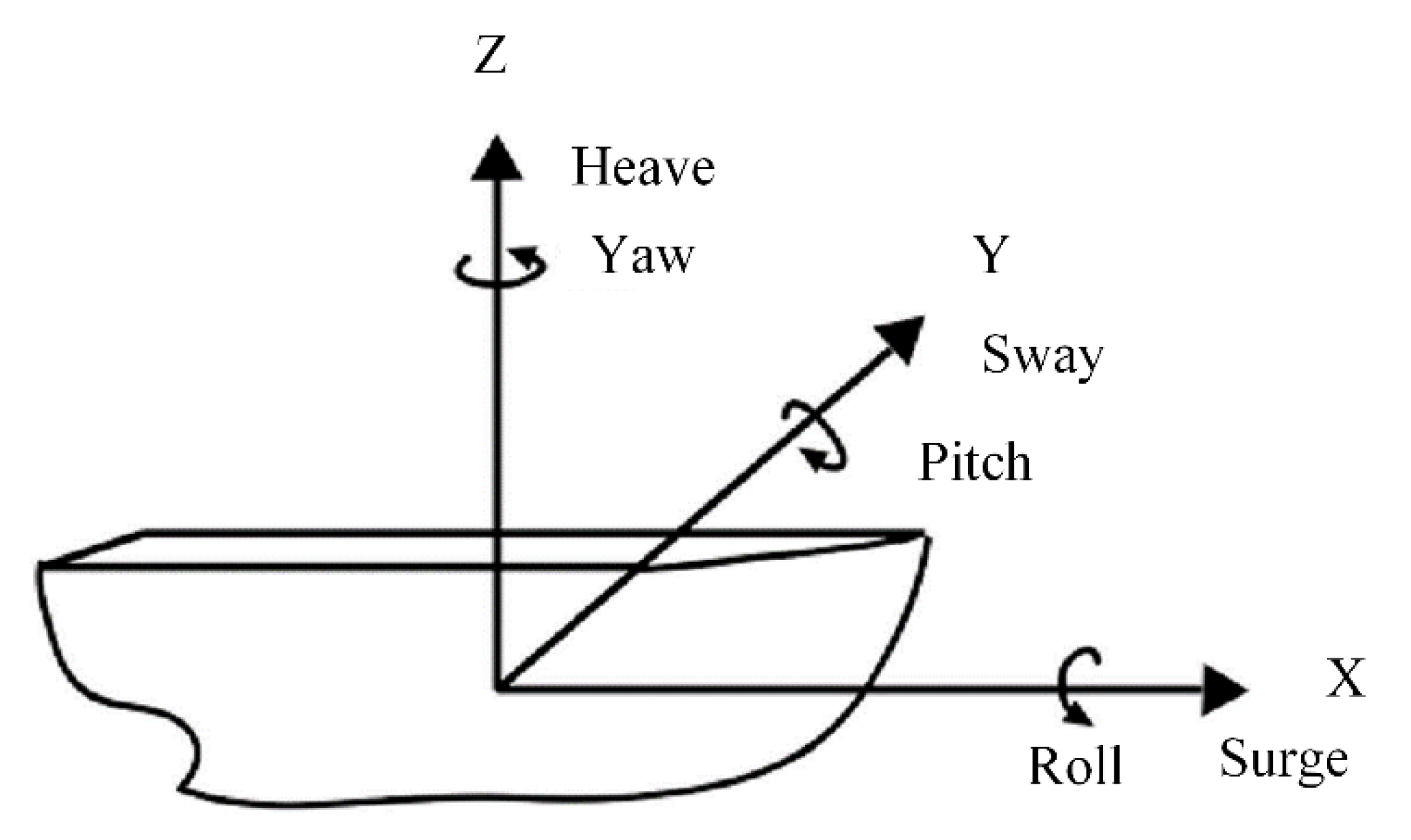
2. Movement Analysis of Heave Compensation Platforms

To make sure a parallel platform is competent for ship motion compensation, a movement ability analysis is required. Among existing approaches, the working space analysis of a parallel manipulator is a visualized description showing its movement capacity in terms of geometry, which is an important index to measure the performance of a motion platform [13].

2.1. Working Space Analysis of 3-RPS Parallel Compensation Platform

The construction of a 3-RPS parallel compensate platform is presented in Figure 2. In the practical application of this type of compensating platform, the sub-platform fixed on the ship deck is the revolute joint attached platform, and the spherical joint attached platform works as the compensation deck. According to the 3-RPS parallel manufacture’s kinematic model [14], the working space of the compensation deck can be acquired.
In terms of decoupling a ship movement under level-4 sea state for which the significant wave height is 2.5 m, the heave compensation platform system needs a vertical moving range of no less than ±1.5 m. For the great capacity of cargo or workers, the area of the compensation deck of this system must be adequate. The prototype was designed with configurations are set as below: both decks of this system are equilateral triangles with a side length of 5 m. The range of the prismatic joint is 3–6 m, and the maximum deflection angle of the spherical joint is 40°.
The forward kinematics of the parallel 3-RPS platform is used to establish the motion model of the compensation platform [15], the constraint range of the movement joints are added, and the workspace of the compensation platform is calculated and drew by MATLAB.
The calculated interval length is 1 cm, and different combinations of prismatic joint lengths are used as inputs to solve the pose of the upper deck of the compensation platform in this case. The images of different attitudes are drawn and shown in Figure 3. In the figure, the lower blue triangle represents the deck fixed platform on the ship deck and the upper part is the moving platform motion space.
As can be seen from Figure 3, in the motion space image of the compensation platform directly drawn, the upper and lower parts of the motion space of the moving platform are all flat, the images of the moving platform solved by different inputs overlap with others badly. The posture of the platform inside the motion space cannot be observed clearly.
In this paper, the workspace of the 3-RPS compensation platform comprises the position workspace, which describes the position of the point lying at the center of the moving platform [16], and the attitude workspace is a diagram that describes the deflection of the moving platform.
Figure 4a shows the workspace of the central point of the moving platform of the parallel 3-RPS compensation platform. To facilitate observation, slices of different heights of the position workspace are drawn, as shown in Figure 4b.
By analyzing Figure 4, the position workspace of the parallel 3-RPS compensation platform has the following characteristics:
  • The highest and lowest point of the position workspace is determined by the range of three prismatic joints; there is only one point at the highest and lowest points of the compensating workspace, where the compensating platform has no deflection ability.
  • The structure of the compensation platform possesses a similar symmetry with its position workspace.
  • The slicing area of the position workspace varies with different heights and increases and then decreases from top to bottom.
Position workspace can only show the variation of platform position, it cannot express the deflection angle of the moving platform, so the attitude workspace is required to show the deflection of the moving platform [17], 3-RPS parallel compensation platform attitude workspace is shown in Figure 5.
Take a point in the contour map and introduce the vector from the central point to the point. The length of the vector represents the deflection angle degree value and the direction of the vector represents the deflection direction. Such as a point within a contour. It indicates that the angle of this platform pose represented by this point can be realized at this height.
The deflection capability of a parallel 3-RPS compensation platform has the following characteristics:
  • Deflection capability of the platform varies with the height of the moving platform. With the height decreases from high to low, the deflection capability of the platform also increases firstly and then decreases.
  • Deflection capability of platforms at the same height and in different directions is not the same. With the change of height, the direction of the maximum deflection angle also changes, and the deflection capability of each direction near the height median is relatively average.

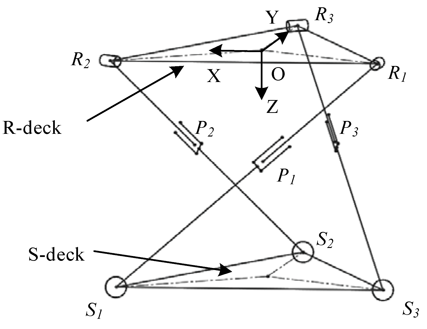
2.2. Workspace Analysis of 3-SPR Parallel Compensation Platform

The structure demonstration of the parallel 3-SPR compensation platform is shown in Figure 6. The motion model of the parallel 3-SPR compensation platform is established by using the same structure size as the 3-RPS platform above. Comparing with the compensation platform based on the 3-RPS parallel structure, the equation sets of the 3-SPR compensation platform is more complex because the revolute joint constraint of the 3-SPR platform is attached to the moving platform [18]. The kinematic of the 3-RPS compensation platform is relatively simple, and the pose of the moving platform corresponds to the solution of leg length [19] Therefore, we can use a method of “inverse solution” to calculate the workspace of the parallel 3-SPR compensation platform.
The inverse solution is illustrated below. First, compute the position of the moving platform of the 3-RPS platform, get the transfer matrix from the mobile platform relative to the deck fixed platform, and then calculate the inverse matrix of this transfer matrix, this process is equivalent to swap the motion platform and fixed platform in the model. This inverse matrix is the transfer matrix represents a movement from the deck fixed platform relative to the moving platform, the last step is using this inverse matrix to perform a point coordinate transformation of the original fixed platform, and the position solution of 3-SPR compensation platform moving platform will show itself. The nonlinear least square method is used to obtain the position workspace and attitude workspace of the 3-SPR compensation platform [20], as shown in Figure 7 and Figure 8.
According to Figure 7 and Figure 8, the workspace of a parallel 3-SPR compensation platform has the following characteristics:
(1)
section shape and section area of the position workspace and attitude workspace varies with the height of the moving platform;
(2)
shape of the position workspace changes dramatically in the area with lower height, while the shape of the position workspace is inert in the area with higher height;
(3)
overall shape of the position workspace and attitude workspace possesses a trilateral symmetry.

2.3. Compensation Feasibility Comparison Analysis

The parallel 3-SPR compensation platform and parallel 3-RPS compensation platform are similar in structure, both of them have the motion capability of three degrees of freedom. However, the volume and shape of the position workspace and the movement capacity of the moving platform vary. The platform which is more suitable for wave compensation operation is selected through comparative analysis.
Firstly, the comparison diagram of attitude workspace is shown in Figure 9. The blue geometry is a 3-SPR compensation platform attitude workspace. The golden one represents the attitude workspace of 3-RPS.
It can be seen that the geometry shape of the attitude compensation space of the two compensation platforms is the same, and the difference lies in the different directions. The maximum deflection capacity of the two platforms is the same, and the deflection capacity varies inversely to the height.
Secondly, moving platform position workspace is compared, as shown in Figure 10. In the figure, the centrally located golden geometry is the position workspace of the 3-RPS compensation platform. The blue transparent geometry is a parallel 3-SPR compensation platform position workspace.
As can be seen from the figure, with the same structural size parameters, the two platforms’ workspaces have the same total height. The position workspace volume of the central point of the 3-SPR platform is much larger than that of the 3-RPS platform, indicating that the 3-SPR compensation platform has stronger horizontal moving capability than the 3-RPS compensation platform.
In the motion space diagram of the moving platform, the position information and attitude information can be better combined, and the work of the two compensation platforms can be more directly compared. In the motion space of the moving platform, different platform poses will render image overlap. Enlarging the calculation interval step can decrease the number of platform positions in the image and using the sidelines of the moving platform to contrast two platforms’ movement. The motion space contrast diagram is shown in Figure 11.
It can be seen that the parallel 3-SPR compensation platform has a large motion space. When the moving platform of the 3-SPR compensation platform performs a compensation movement, the central point of the moving platform will have a large horizontal displacement relative to the vertical line passing through the central point of the fixed platform. This movement is called platform parasitic movement [18]. The amplitude of platform parasitic movement is proportional to the deflection angle of the platform. The parasitic movement of the moving platform also exists in the deflection of the moving platform of the 3-RPS compensation platform, but the amplitude of the parasitic movement is much smaller.
From this we can conclude that: those two compensation platforms possess the same deflection capability but the orientation of the attitude workspace is inversed; The 3-SPR parallel compensation platform covers a bigger room of position workspace than the 3-RPS parallel compensation platform does; 3-SPR parallel compensation platform owns a stronger horizontal moving ability and its moving platform deflection simultaneously causes obvious platform parasitic movement.
It should be pointed out that, due to the finite area of the ship’s deck, a compensation platform cannot be installed on the center of the ship deck, and there is an inevitable distance between the moving platform and fixed platform, so the ship rolling and pitching movement will consequently make moving platform produce an associated sway and surge movement relative to the fixed platform; thus, a compensation system shall have the ability to compensate this movement. By comparing the workspace of the 3-RPS compensation platform and the 3-SPR compensation platform, we can know that the ability of the 3-RPS compensation platform to compensate for horizontal movement is far less than that of the 3-SPR compensation platform.
Under the same ship attitude condition, both the 3-RPS platform and the 3-SPR platform of the same size produce an ideal compensation effect. The comparison of the compensation effect is shown in Figure 12.
From the ideal comparison effect of the two platforms, it can be indicated that the 3-RPS compensation platform cannot effectively compensate for the associated sway and surge caused by the rolling and pitching of the ship movement. In contrast, the 3-SPR compensation platform can reduce this movement by its horizontal moving ability. Therefore, in the practical wave compensation system installation, the parallel 3-SPR compensation platform is more competent.

3. Structural Optimization Design of Parallel 3-SPR Compensation Platform

For waves with a significant wave height of 2.5 m, the heave compensation platform should have a vertical motion range of 3 m to compensate for the ship movement. The vertical distance between the lowest pose of the platform and the ship deck should be at least 3 m, and the vertical distance should be 4.5 m when the compensation system is in the ready phase, and the vertical height can reach 6 m at the highest pose. In the actual system, such a height is very dangerous. Meanwhile, the cylinder rod is getting more easily to lose stability with the cylinder’s elongation extend. Therefore, on the premise of not changing the total height of the position workspace of the platform, the height of the moving platform and the elongation of the cylinder rod should be reduced as much as possible.
Structural optimization method 1: changing the area ratio of upper and lower platforms. By changing the area ratio between the upper platform and the lower platform, the dexterity of the platform can be increased, but the area of the upper platform should not be too small, and the optimal situation is that the upper platform area is half of the area of the lower platform [14]. However, this method has no obvious effect on the reduction of the working height of the heave compensation platform and the shortening of the cylinder rod elongation.
Structural optimization method 2: involving the motion of the revolute joint in heave compensation. The mechanism of the revolute joints participating in heave compensation is shown in Figure 13. The vertical height of the end of the leg can be directly affected by the angle change of the revolute joint when the length of the rod is unchanged. In the previous heave compensation platform motion, the rotation ability of the revolute joint was not fully utilized. Therefore, the structure of the compensation platform could be changed to make the revolute joint fully participate in the compensation motion [21].
The first optimization structure is changing the corresponding mode of the spherical joints and the rotating joints. Rotate the moving platform by 180° around the axis passing the vertical direction of the central point without changing the corresponding relationship between revolute joints and spherical joint. To avoid the collision of the three branch support legs, each leg is divided into two sections in the middle and interlaced with each other. The specific structure is shown in Figure 14.
This structure has solved the problems in the original platform such as the extent of the high altitude of the upper deck and length of branch legs. To compensate ship movement under level 4 sea state, the platform height of neutral position goes down from 4.5 m to 3.5 m, prismatic joints elongation can be reduced from the original 3 m down to 2.2 m, and the platform still has the extremely good deflection ability. However, the structure of this type of platform is complex, and it is also more difficult to synchronize the two cylinders on the same branch leg.
In the second optimization structure, the arrangement of the revolute joints and the corresponding mode between the rotation joints and the spherical joints are changed [21]. The axes of those three revolute joints rotate 30° counter-clockwise (or clockwise) around their vertical direction at the same time. Meanwhile, the corresponding modes between the rotation joints and the spherical joints are transferred counterclockwise (or clockwise), too. The structure diagram of the improved platform is shown in Figure 15.
The second form of structure optimization is simple in structural expression and easy to build in practice, and the revolute joint fully participates in the compensation movement of the platform. However, the motion model of the compensation platform has changed greatly. A new calculation of its working space is required. The motion model of this novel compensation platform is analyzed below.

4. Modeling and Analysis of the Optimized 3-SPR Platform

To facilitate explaining, the platform connected with the spherical joint is named as S-deck, and the other platform connected with rotation joints is called R-deck. Three branch legs are represented by S 1 P 1 R 1 , S 2 P 2 R 2 , S 3 P 3 R 3 , with S i , P i , R i respectively indicate spherical joints, prismatic joints and rotation joints. Establishing coordinate system, make the origin located at the center of the R-deck, with Y axis pointing to vertex R 3 , Z axis pointing vertically down, and the X axis is defined by the right-hand rule.
As shown in Figure 16, the revolution axis of the R 1 point rotation joint of the new platform is perpendicular to the line connecting R 2 , and R 1 point. The revolution axis of the rotation joint of R 2 point is perpendicular to the line connecting R 3 R 2 point, and the revolution axis of R 3 point rotation joint is perpendicular to the line connecting R 1 R 3 point.
Set R-deck as equilateral triangle, with side length L, and set the coordinates of the three vertices as
R 1 = [ L 2 3 L 6 0 ]   R 2 = [ L 2 3 L 6 0 ]   R 3 = [ 0 3 L 3 0 ]
Set the length of the three branch chains be respectively as g 1 , g 2 , g 3 .
Name the point of spherical joint that connected on the same branch leg with rotation joints R i as S i . and its coordinates are assigned as
S 1 = [ x 1 y 1 z 1 ]   S 2 = [ x 2 y 2 z 2 ]   S 3 = [ x 3 y 3 z 3 ]
Due to the movement of rotation joints only possess one degree of freedom, the vertex S 1 must be located in a plane which is perpendicular to R-deck and with line R 1 R 2 on it. The same as S 2 to line R 2 R 3 and S 3 to line R 1 R 3 . These three planes are named as plan R 1 R 2 S 1 , plan R 2 R 3 S 2 and plan R 3 R 1 S 3 . Therefore, the x-coordinate value in S 1 , S 2 , S 3 has the following relationship with the y-coordinate value
{ y 1 = 3 L 6 y 2 = 3 x 2 + 3 L 3 y 3 = 3 x 3 + 3 L 3
and the coordinate of three vertices is changed into
S 1 = [ x 1 3 L 6 z 1 ]   S 2 = [ x 2 3 x 2 + 3 L 3 z 2 ]   S 3 = [ x 3 3 x 3 + 3 L 3 z 3 ]
Since the length of those three branch legs are represented as g 1 , g 2 , g 3 , so the trajectory of vertex S 1 is a special circle that uses vertex R 1 as the center, g 1 as the radius, and be on the plane comprising vertex R 1 , R 2 , and S 1 . The trajectory of vertex S 2 and S 3 can also be obtained by this way. Those three trajectories’ functions are shown below.
{ ( x 1 + L 2 ) 2 + z 1 2 = g 1 2 4 ( x 2 L 2 ) 2 + z 2 = g 2 2 ( 4 x 3 ) 2 + z 3 2 = g 3 2
There is another constrain that the length of the side of deck-R is L, so the functions that expressing this relationship are shown below.
| S 1 S 2 | = | S 2 S 3 | = | S 3 S 1 | = L
Calculate the side length using vertices’ coordinate and then simplify those equations. We can get the functions
{ ( x 1 x 2 ) 2 3 ( x 2 1 2 L ) 2 + ( Z 1 Z 2 ) 2 = L 2 ( x 2 x 3 ) 2 3 ( x 2 + x 3 ) 2 + ( Z 2 Z 3 ) 2 = L 2 ( x 3 x 1 ) 2 3 ( x 3 + 1 2 L ) 2 + ( Z 3 Z 1 ) 2 = L 2
Combining Equations (5) and (7), we can get
{ ( x 1 + L 2 ) 2 + z 1 2 = g 1 2 4 ( x 2 L 2 ) 2 + z 2 = g 2 2 ( 4 x 3 ) 2 + z 3 2 = g 3 2 ( x 1 x 2 ) 2 3 ( x 2 1 2 L ) 2 + ( Z 1 Z 2 ) 2 = L 2 ( x 2 x 3 ) 2 3 ( x 2 + x 3 ) 2 + ( Z 2 Z 3 ) 2 = L 2 ( x 3 x 1 ) 2 3 ( x 3 + 1 2 L ) 2 + ( Z 3 Z 1 ) 2 = L 2
Equation (8) is a nonlinear system of equations, using the nonlinear least square method to solve it and the coordinate of those three spherical joint centers can be derived. Using the coordinate values to calculate the transform matrix representing the movement from the R-deck to the S-deck. Reverse the matrix and using the reversed matrix can we derive the coordinates of rotate joint centers after the movement of the R-deck to the S-deck.
The position workspace, shown in Figure 17a, and attitude workspace, shown in Figure 17b, of this new rotated 3-SPR compensation platform can be drawn by calculating all the feasible positions of the center point of the R-deck and all feasible angles that the R-deck can reach.
It can be seen that the workspace of the 3-SPR compensation platform mentioned above and the workspace of the new rotated 3-SPR compensation platform possesses similar volume and shape, which means the new platform is competent for compensating the sway and surge movement concomitant to the roll and pitch movement of a vessel. It also can be seen that the height of the compensation platform workspace has been reduced.

5. Results and Discussion

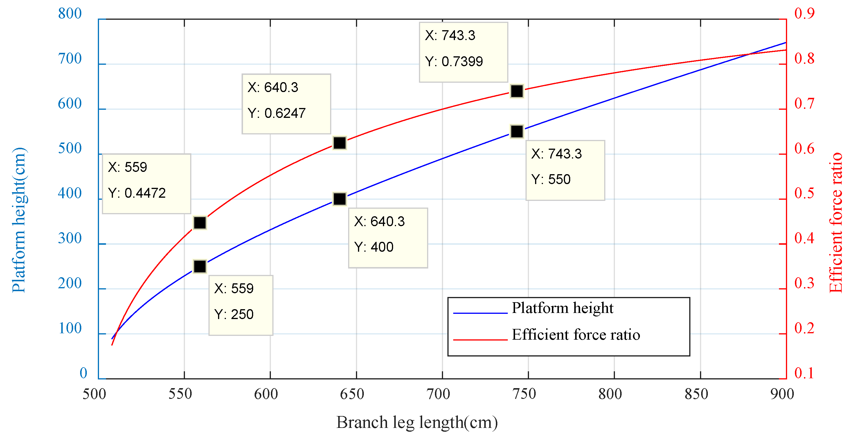
5.1. Working Height and Side Length Optimization

The working height and altitude of the new compensation platform is no longer determined by the prismatic joint alone, but influenced by the angle of the rotating joint and prismatic joint together. At the same time, the branch legs do not support the R-deck vertically, so the effective component of support force also changes with the height of the platform. Finding out the relationship between those elements will facilitate the equipment configuration design and establishment of a control system.
First, the correlation of branch leg elongation and the neutral height with different side lengths is discussed. The neutral height is the height of the medium position of a compensation platform, to completely decouple the ship motion under 4-level sea condition, the height of the position workspace of the novel compensation platform is set to 3000 mm. The relation of those three elements is shown in Figure 18.
It can be seen that, with the same side length of the deck of compensation platform, the increase of the neutral height of the platform leads to the increase in the elongation of the branch leg, and with the same neutral height of the compensation platform, the decrease in side length also leads to increase in elongation of branch legs. Therefore, for the purpose of decreasing the elongation of branch legs, the side length of the compensation platform should be set as long as possible and the neutral height should be set as low as possible.
Another aspect to be discussed is the percentage of the efficient support force of the branch legs. Due to the branch legs no more support the moving deck of the compensation platform vertically, the proportion of force that propping up the moving deck is related to the height of the moving deck. The efficient support force can be calculated using Equation (9) below, where F e represents the efficient force, F a represents the actuation force, and θ represents the angle of the revolute joint of the branch leg.
F e = F a × s i n θ
The bar chart in Figure 19 shows the relation between the percentage of efficient support force of a branch leg calculated according to the lowest position of the moving deck of different neutral heights. The side length is also involved in the discussion of different conditions.
As the figure shows, with the increment of the neutral height of the compensation platform under a certain side length, the percentage of efficient support force goes up, and reducing the side length without changing the neutral height can also provide more efficient support force from the branch leg to the moving deck. Thus, we may conclude that: to increase the efficient force, the side length should be reduced and the neutral height should be set at a high value.
Comparing the conclusions discussed above, the effect of side length and neutral height of compensation platform on the elongation of branch legs and percentage of efficient support force is approximately opposite. For the purpose to make the compensation platform possess the same capacity as the original platform set the side length to 5 m. The correlation of platform height, length of leg, and efficient force percentage is shown in Figure 20.
To make sure the compensation platform has a good active reaction, the proportion of efficient force should not be too low. Therefore, the optimized neutral height of the compensation platform is set to 4 m with the efficient force ratio goes to 62.47%, and due to the height of the workspace is 3 m, the lowest position of the moving deck is 2.5 m with the percentage of efficient support force is 45%.
The new platform also owns a faster movement response than the old one. For instance, when the platform height increases from 250 cm to 400 cm, the branch legs length only needs to increase by 81.3 cm.
The height of workspace of this compensation platform can also be moderated to face different needs. For instance, if the compensation platform is using to decouple the ship movement from a heavy cargo or machine, the neutral height of this platform should be increased to provide more percentage of efficient support force, and if this platform is used to compensation the wave motion for a lightweight one or be used as a part of the heave compensation gangway for transportation, the neutral height can be set lower to make the movement of the moving platform more flexible and get a faster actuation response.

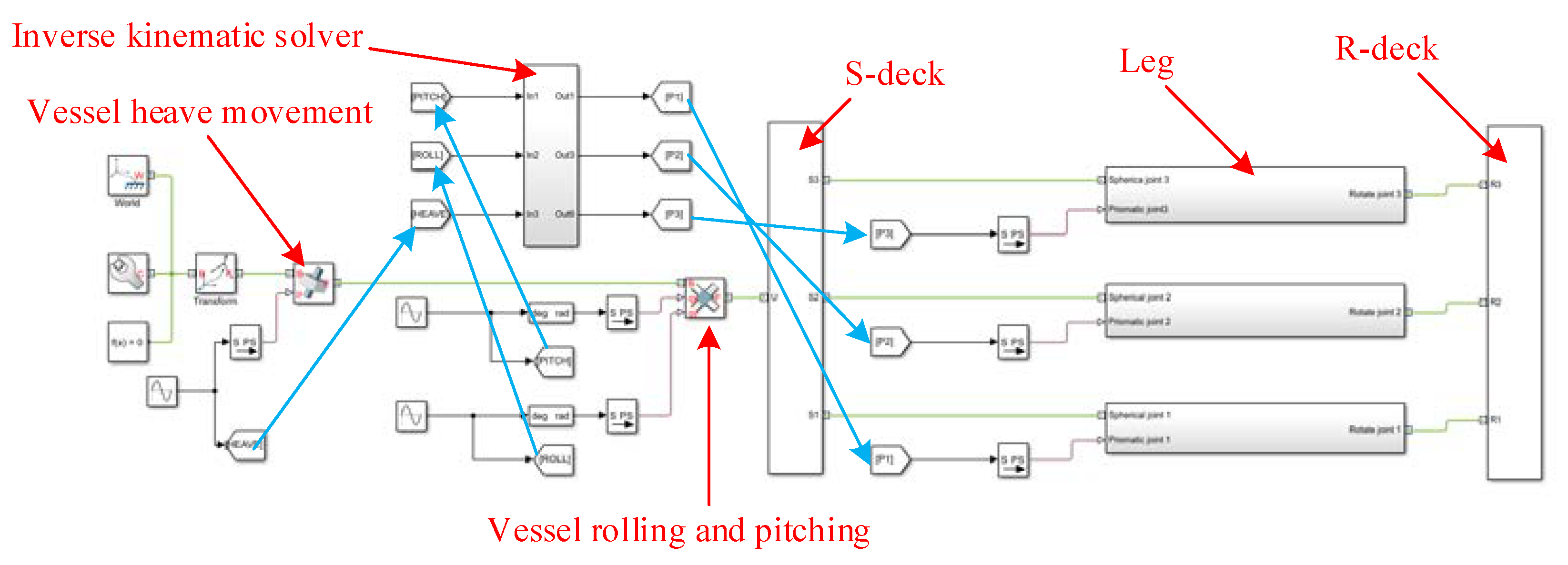
5.2. Compensation Movement Simulation

The kinematic simulation model is built to analysis the effect of the wave compensation and compare the performance of the novel platform with the original one. The simulation model in Simulink is shown in Figure 21.
Solidworks is used to draw the structure model of the new 3-SPR compensation platform and import the assembly model into the Simscape module of Simulink. This simulation includes an inverse kinematic [22] solver which is designed according to the structure model message. This solver can calculate, online, branch legs’ length that compensates the vessel movement by inputting the value of heave motion, pitch, and roll of the vessel.
Employing a prismatic joint and a universal joint between the S-deck and the rigid ground coordinate of this Simulink model. Utilize the prismatic joint motion to simulate the heave movement of the vessel and the universal joint revolution to imitate the rolling and pitching. The subsystem of a branch leg in Simulink model is shown in Figure 22.
The maximum values of vessel motion are important to this simulation for they directly determine the structural configuration of the compensation platform, and whether the platform is capable for this job. In contrast, the verisimilitude of the vessel motion is less important which means simplifying the component of the wave will not affect the result of simulation distinctly. The significant amplitude of heave motion under 4-level sea states is about 1.25 m, and the maximum rolling angle is proximate 10 degrees, and the pitching angle is smaller. In order to make the results easier to be read and let the figure show more periods, the components of the wave have been simplified and the frequency of all movements has been increased. To make sure the compensation platform can fully compensate the ship motion, all the amplitude of movement has been amplified. The vessel motion under 4-level sea status is simulated using the coefficient written below in Table 1. Figure 23 and Figure 24 show the time history of ship heave, rolling, and pitching motion.
Figure 25 shows the leg elongation of the novel structure during the compensation process to the simulative wave above. To compensate a ±1.5 m wave, the support legs of the novel compensation platform need to possess a range of elongation of about 2.3 m.
Figure 26 presents the leg elongation of the original platform during the process of compensation to the simulative wave. As shown in the picture, to compensate that wave, the support legs of the old compensation platform need to have a 4 m elongation range at least.
Therefore, the simulation of the compensation process of both novel and original platform comes to the conclusion that the novel compensation platform has a smaller range of support legs’ elongation than the old one under the same condition of wave height. Meanwhile, a shorter range during the same time indicates a smaller elongation speed. The diagrams contain the velocity of the branch legs’ extension movement of both platform structures during the compensation process is below.
By comparing Figure 27 and Figure 28, it can be seen that the maximum velocity of support legs of the novel compensation platform is about 0.9 m/s, but the old one is 1 m/s. In addition, the maximum velocity of the leg 2 of the old platform is up to 1.5 m/s. To compensate the same wave, the support legs of the novel compensation platform need smaller velocity than the old one, which means the movement response of the new platform is faster.
Due to the structural constraints, the parasitic movement of the parallel platform is unavoidable. A move simulation of the moving platform during the compensation process is done to analyze the compensation effect of the novel compensation platform. The heave roll and pitch movement of the moving platform after compensation is shown in Figure 29 and Figure 30 respectively.
It can be seen in Figure 31 that the associated movement is about 0.1 mm which is difficult to feel. Generally speaking, the heave movement of vessel has been reduced by 99.96%, rolling movement has been alleviated by 97.74%, and the angle of pitch movement has been reduced by 97.28%.

6. Conclusions

Considering the range of vessel motion under level-4 sea state, compensation platforms based on 3-RPS parallel structure and 3-SPR parallel structure were presented. Using forward kinematic methodology, we analyzed the compensation ability, and the workspace of both compensation platforms were drawn.
By comparing the position work space and the attitude workspace, associating with the parasitic movement of both platforms, we came to the conclusion that the 3-SPR parallel structure is more competent for vessel movement compensation than the 3-RPS parallel structure.
In order to enhance the safety and actuating response of the compensation platform, a structure optimized 3-SPR parallel platform was designed which has a lower workspace altitude and shorter elongation range of branch legs. Using the forward kinematic method calculated the workspace and verified its feasibility of compensating.
A simulation model of the vessel motion compensation using the novel parallel structure and the original platform were built. Employing the inverse kinematic method as the movement solver, the performance of the compensation processes were compared. The feasibility and efficiency of the novel compensation platform was verified and calculated. After being compensated by the novel compensation platform, the heave movement of vessel was reduced by 99.96%, rolling movement can be alleviated by 97.74%, and the angle of pitch movement was reduced by 97.28%.

Author Contributions

Conceptualization, Y.Z., J.X., H.T., J.F., and S.W.; Methodology, Y.Z., J.X., H.T., J.F., and S.W.; Software, H.T., J.F., and S.W.; Validation, Y.Z. and H.T.; Formal analysis, Y.Z., H.T., and S.W.; Investigation, Y.Z.; Resources, J.X. and Z.Y.; Data curation, J.F.; Writing—original draft preparation, Y.Z. and H.T.; Writing—review and editing, Y.Z., H.T., and J.F.; Visualization, Y.Z.; Supervision, Y.Z. and J.X.; Funding acquisition, Y.Z. and J.X. All authors have read and agreed to the published version of the manuscript.

Funding

The authors gratefully acknowledge the financial support from The Natural Science Foundation of Heilongjiang Province, China (no. E2018022), Information Technology of the People’s Republic of China-Floating Security Platform Project (the second stage), and the Opening Fund of Acoustics Science and Technology Laboratory (grant no. SSKF2020009).

Acknowledgments

The authors would like to thank the members of the Marine Electromechanical Systems Research Institute for their continued support and discussion.

Conflicts of Interest

The authors declare that the research was conducted in the absence of any commercial or financial relationships that could be construed as a potential conflict of interest.

References

  1. Han, C. Design and Research of Active Heave Compensation System Based on Laser Ranging Sensor. World J. Eng. Technol. 2020, 8, 13–18. [Google Scholar] [CrossRef] [Green Version]
  2. Li, B.; Zhao, X. Position Analysis of A 3-Spr Parallel Mechanism. J. Theor. Appl. Inf. Technol. 2013, 48, 8. [Google Scholar]
  3. Wei, L.; Limin, T.; Zhengnan, J. Design and control of cable-drive parallel robot with 6-dof active wave compensation. In Proceedings of the 2017 3rd International Conference on Control, Automation and Robotics (ICCAR), Nagoya, Japan, 24–26 April 2017; pp. 129–133. [Google Scholar]
  4. Gu, Y.-F.; Xie, R.; She, J.-G. Optimization design of heave compensation device platform under six level of sea condition. Ship Sci. Technol. 2017, 39, 141–145. [Google Scholar]
  5. Markus Richter, E.A.; Klaus, S.; Johannes, K. Oliver Sawodny Model Predictive Trajectory Planning with Fallback-Strategy for an Active Heave Compensation System. In Proceedings of the 2014 American Control Conference (ACC), Portland, OR, USA, 4–6 June 2014. [Google Scholar]
  6. Zhang, Y.; Ma, S.; Duan, W. Linear time-domain strip method for ship motion prediction. Chin. J. Ship Res. 2018, 13, 1–6, 28. [Google Scholar]
  7. Su, C.; Zheng, W.; Zeng, Y.; Ding, D. An Active Wave Compensation Method for the Gangway of Wind Turbine Maintenance Vessel. Naval Archit. Ocean Eng. 2017, 33, 22–25. [Google Scholar]
  8. Ngongi, W.; Du, J.; Massami, E.; Chang, W.-J.; Kassembe, E. Dynamic positioning of ships based on robust fuzzy observer. J. Eng. 2020, 2020, 228–238. [Google Scholar] [CrossRef]
  9. Wang, W. Kinematics Analysis of Wave Motion Compensation Stable Platform. Shipbuild. Technol. Res. 2019, 4. [Google Scholar] [CrossRef]
  10. Sun, Z.; Zhao, Q.; Wang, N.; Qin, Y. Modeling and Control of 3—RPS Parallel Vibration Isolation Platform. For. Eng. 2020, 36, 69–76. [Google Scholar]
  11. Nayak, A.; Wenger, P.; Caro, S. Comparison of 3-RPS and 3-SPR parallel manipulators based on their maximum inscribed sigularity-free. New Trends Mech. Mach. Sci. 2018, 121–130. [Google Scholar]
  12. Tang, G.; Hu, C.; Hu, X. Modeling and simulation of three-degree-of-freedom parallel wave compensation platform. J. Shanghai Marit. Univ. 2020, 41, 20–26. [Google Scholar]
  13. Zhou, B.; Mao, T.; Yang, R. Workspace Analysis of 3- dof RPS Parallel Mechanism. J. Hunan Univ. Nat. Sci. 2003, 58–61. [Google Scholar]
  14. Hongmei, Y. The Kinematics Analysis of 3-RPS Parallel Machine Tool; Northeastern University: Liao Ning Province, China, 2013. [Google Scholar]
  15. Lu, Y.; Zhao, Y. Position and workspace analyses of 3-SPR and 3-RPS parallel manipulators. In Proceedings of the International Design Engineering Technical Conferences and Computers and Information in Engineering Conference, Long Beach, CA, USA, 24–28 September 2005; pp. 957–962. [Google Scholar]
  16. Zhang, F.; Jia, Y.; Zhang, C.; Liang, K. Research on Design and Simulation of 3-RPS Parallel Stable Platform. Mach. Build. Autom. 2018, 47, 145–148. [Google Scholar] [CrossRef]
  17. Zhang, L.-J.; Guo, F.; Liu, S.-Y. Deflection capacity analysis of moving platform of a 3-RPS parallel mechanism. J. Yanshan Univ. 2012, 36, 196–200. [Google Scholar]
  18. Nayak, A.; Stigger, T.; Husty, M.L.; Wenger, P.; Caro, S. Operation mode analysis of 3-RPS parallel manipulators based on their design parameters. Comput. Aided Geom. Des. 2018, 63, 122–134. [Google Scholar] [CrossRef] [Green Version]
  19. Shi, Y.; Hao, Q.; Xu, G.; Lu, Y. Analysis about the Relationship Between Platform Size and Workspace of a Plane Symmetry 3-SPR Parallel Manipulator. Mach. Des. Manuf. 2012, 37–39. [Google Scholar]
  20. Rad, C.; Stan, S.; Bălan, R.; Lapusan, C. Forward kinematics and workspace analysis of a 3-RPS medical parallel robot. In Proceedings of the 2010 IEEE International Conference on Automation, Quality and Testing, Robotics (AQTR), Cluj-Napoca, Romania, 28–30 May 2010; pp. 1–6. [Google Scholar]
  21. Shi, Y.L.Y. Analysis about workspace of 3-SPR parallel manipulator influenced by the joints’distribution. J. Yanshan Univ. 2008, 304–310. [Google Scholar]
  22. Hu, B.; Jing, Y.L.; Yu, S.Z. Analyses of inverse kinematic, statics and workspace of a novel3RPS-3SPR Serial-Parallel manipulator. Open Mech. Eng. J. 2011. [Google Scholar] [CrossRef]
Figure 1. Six-degrees-freedom motions of the vessel.
Jmse 08 01013 g001
Figure 2. 3-RPS parallel compensate platform.
Jmse 08 01013 g002
Figure 3. 3-RPS parallel compensate platform motion space.
Jmse 08 01013 g003
Figure 4. Position workspace of 3-RPS compensation platform; (a) 3D shape of the position workspace; (b) slice figure of different altitudes.
Jmse 08 01013 g004
Figure 5. Attitude workspace of 3-RPS compensation platform, (a) is the attitude workspace image, (b) is a contour map derived from the attitude workspace.
Jmse 08 01013 g005
Figure 6. 3-SPR parallel compensation platform.
Jmse 08 01013 g006
Figure 7. Position workspace of the 3-SPR compensation platform. (a) The 3D shape of the position workspace; (b) slice figure of different altitudes.
Jmse 08 01013 g007
Figure 8. Attitude workspace of 3-SPR compensation platform, (a) is the attitude workspace image, (b) is a contour map derived from the attitude workspace.
Jmse 08 01013 g008
Figure 9. Attitude workspace comparison diagram of two platforms.
Jmse 08 01013 g009
Figure 10. Position workspace comparison of two platforms.
Jmse 08 01013 g010
Figure 11. Moving platform motion space comparison: (a) is a parallel platform moving platform 3-RPS compensation movement space; (b) is the 3-SPR parallel compensation platform’s motion space. In both figures, the solid triangular pattern at the bottom indicates the fixed platform, while the solid triangular lines at the top forms the moving platform under different poses.
Jmse 08 01013 g011
Figure 12. Compensation effect comparison; (a) is the compensation effect of the 3-RPS compensation platform; (b) is the compensation effect of the 3-SPR compensation platform.
Jmse 08 01013 g012
Figure 13. Mechanism of revolute joints participating in compensation to heave motion.
Jmse 08 01013 g013
Figure 14. The first type of optimized structure.
Jmse 08 01013 g014
Figure 15. The second optimization structure.
Jmse 08 01013 g015
Figure 16. Structure demonstration of optimized compensation platform.
Jmse 08 01013 g016
Figure 17. Position workspace and attitude workspace of the novel compensation platform. (a) is the position workspace of the new platform. (b) is the attitude workspace of the new platform.
Jmse 08 01013 g017
Figure 18. Correlation between branch leg elongation and neutral height under different side length circumstance.
Jmse 08 01013 g018
Figure 19. Correlation between the percentage of vertically support force of branch legs and neutral height under different side length circumstances.
Jmse 08 01013 g019
Figure 20. Curve of the relationship between branch leg length and the percentage of efficient support force, and the curve of the relationship between platform height and prismatic joint length.
Jmse 08 01013 g020
Figure 21. Diagram of simulation in Simulink.
Jmse 08 01013 g021
Figure 22. Subsystem diagram under the leg section mask is composed of a spherical joint, a prismatic joint and a revolute joint. Using the prismatic joint as the actuator, and the spherical joint and revolute joint are respectively connected to the S-deck and the R-deck. The direction of different legs is determined by rigid transform module under the R-deck system.
Jmse 08 01013 g022
Figure 23. Heave movement of vessel.
Jmse 08 01013 g023
Figure 24. Roll movement and pitch movement of vessel.
Jmse 08 01013 g024
Figure 25. Leg elongation extent of the novel wave compensation platform.
Jmse 08 01013 g025
Figure 26. Leg elongation extent of the original wave compensation platform.
Jmse 08 01013 g026
Figure 27. The velocity of support legs of the novel compensation platform during the compensation to the simulative wave.
Jmse 08 01013 g027
Figure 28. Velocity of branch legs of the original compensation platform during the compensation to the simulative wave.
Jmse 08 01013 g028
Figure 29. Heave movement of the R-deck of the compensation platform. The final movement range is less than 1 cm.
Jmse 08 01013 g029
Figure 30. Rolling value and pitching value of the R-deck of the compensation platform. The maximum rolling angle is less than 0.34 degrees and the biggest pitch angle is 0.136 degrees. Both are drastically less than the revolute movement of the vessel.
Jmse 08 01013 g030
Figure 31. Associated movement of the R-deck along axis x and axis y. The associated movement is caused by the parasitic movement of the parallel platform structure.
Jmse 08 01013 g031
Table 1. Vessel motion simulating configuration.
HeaveRollingPitching
Amplitude1500 mm15 degree5 degree
Frequency (rad/s)0.510.5
Phase (rad)000.1
Publisher’s Note: MDPI stays neutral with regard to jurisdictional claims in published maps and institutional affiliations.

