Article

A Novel Method for Simultaneous Removal of NO and SO2 from Marine Exhaust Gas via In-Site Combination of Ozone Oxidation and Wet Scrubbing Absorption

1
Marine Engineering College, Dalian Maritime University, Dalian 116026, China
2
Liaoning Research Center for Marine Internal Combustion Engine Energy-Saving, Dalian Maritime University, Dalian 116026, China
3
Yantai Office, Qingdao Branch, China Classification Society, Yantai 264000, China
4
College of Ocean Engineering, Guangdong Ocean University, Zhanjiang 524088, China
*
Authors to whom correspondence should be addressed.
J. Mar. Sci. Eng. 2020, 8(11), 943; https://doi.org/10.3390/jmse8110943
Submission received: 8 October 2020 / Revised: 10 November 2020 / Accepted: 16 November 2020 / Published: 20 November 2020
(This article belongs to the Section Ocean Engineering)

Abstract

:
The stringent international regulations on marine emission abatement have exerted a huge push on the development of marine desulfurization and denitrification technologies. However, for the traditional vessels driven by large two-stroke diesel engines, simultaneous removal of NOx and SO2 is still a big challenge at present. Here, a one-stage ozone oxidation combined with in-situ wet scrubbing for simultaneous removal of NO and SO2 is proposed. A series of experiments were performed based on a bench-scale reaction system. The results showed that in-situ wet scrubbing could effectively decrease flue gas temperature, and then suppress the thermal decomposition of ozone, which was beneficial for improve oxidant utilization. Meanwhile, the in-situ combination of ozone injection and wet scrubbing was in favor of improving the selectivity oxidation of NO over SO2 by ozone, which was possibly due to the high aqueous solubility of SO2 in water. Aiming to reduce the electric power consumption by an ozone generating system, O3/NO molar ratio was kept as low as possible. A complete removal of SO2 and a high NOx removal efficiency could be achieved through the introduction of other oxidative additives in scrubbing solution. This integrated system designed for marine application was of great significance.

1. Introduction

Increasingly stringent regulations on marine gaseous pollutant emissions have come into force in recent years [1]. The global shipowners are facing unprecedented pressure to take measures to abate multiple kinds of pollutants (such as SOx, NOx, CO2, and PMs) from marine exhaust gas, since these pollutants would impose very negative effects on global climate change and ecological environment [2]. International Maritime Organization (IMO) set a goal to reduce at least 50% of greenhouse gas emission by global marine industry for 2050 compared with that for 2008. A possible method is to develop novel propulsion technologies for ocean-going vessels. Currently, more interests are focused on non-fossil fuels, such as Liquified Natural Gas (LNG), NH3, H2, methanol, and biogas, as alternative fuels for marine propulsion plants. Undoubtedly, once these alternative fuels are applied extensively in marine industry, they would greatly reduce the emissions of greenhouse gas together with other atmospheric pollutants. However, the majority of ship fleets are still powered by traditional diesel engines at present, and it requires a number of years for shipowners to replace the existing vessels by clean energy ships. Therefore, there are urgent needs for novel emission abatement technologies for ship operators to satisfy the strict regulations. Since 1 January 2020, the limit on sulfur content in marine fuel oil has been changed from 3.5 down to 0.5 wt.% for global navigation. In addition, newly built ships are required to reduce NOx emission concentration greatly when sailing in international emission control areas (ECAs). Thus, an exhaust gas treatment system that could control SOx and NOx simultaneously would be a good choice for shipowners as a short-term solution.
Since sulfur oxides (SOx) mainly originate from the combustion of high-S fuel oil in diesel engines, it can be largely reduced to a very low level by taking low-S or no-S fuels, such as marine gas oil (MGO), LNG, biological methanol, et al., as alternative fuels [3,4]. Meanwhile, a wet scrubber, which is similar to a stationary sources desulfurization system, can also be used to remove SOx efficiently, especially open-loop seawater scrubbers have become a popular choice for international ship owners [5]. However, neither adopting low-S fuel or installing a wet scrubber could reduce NOx emission effectively. To date, selective catalytic reduction (SCR) and exhaust gas recirculation (EGR) techniques are two relatively mature denitration methods for marine diesel engines [6,7]. There are several possible solutions for ocean-going ships to control SOx and NOx emissions simultaneously: ultra-low-S fuel + SCR, ultra-low-S fuel + EGR, wet scrubber + SCR, wet scrubber + EGR, etc. However, there are some obvious drawbacks for such a combination system: high installation and maintenance cost, complex operation, large installation space, low operation economy [8]. The above-mentioned solutions have a lack of practicality. Thus, innovative multiple-pollutant abatement technologies are still in urgent demand for marine industry.
A great deal of research work has been conducted to study how to remove SOx and NOx simultaneously during recent decades. However, most of it focused on land-based stationary sources. There were some obvious differences in technical demands between stationary sources and mobile sources. Ships are a typical kind of mobile source. Their engine space and energy supply are very limited, which require SOx and NOx removal systems to be as compact as possible. Since it is difficult to remove SOx and NOx simultaneously through a dry-method system, a great effort has been made to develop a wet-method system for marine application. The main component of NOx emitted from diesel engines is NO, whose proportion could be more than 95%. The solubility of NO in water is quite low, resulting in a low removal efficiency in traditional wet scrubber. A feasible way to improve NOx removal efficiency is to introduce some other oxidative additives into the scrubbing solution. Some common oxidants, such as NaClO [9], NaClO2 [10], H2O2 [11], Na2S2O8 [12], ClO2 [13], and O3 [14], have been investigated to oxidize NO into higher valance NOx. Since the solubilities of higher valance NOx are much higher than that of NO, a high NOx removal efficiency has been obtained in the previous research. Zhou et al. used Na2S2O8 as an oxidant to simultaneously absorb SO2 and NO from marine diesel engine exhaust gas. Their lab-scale experimental results showed that 900 ppm SO2 and 1000 ppm NO could be completely absorbed under nonoptimal conditions [12]. Zhang et al. conducted in a pilot-scale photochemical spraying tower to investigate the simultaneous removal of SO2 and NO from flue gas using H2O2/urea activated by vacuum ultraviolet (VUV) light, and the results showed that SO2 could attain complete removal, and NO removal efficiency was enhanced greatly through increasing the VUV irradiation intensity and H2O2 concentration [11]. Han et al. carried out a series of experiments to study the simultaneous removal of NO and SO2 from simulated exhaust gas by cyclic scrubbing and on-line supplementing pH-buffered NaClO2 solutions based on a bench-scale reactor. The results indicated that both SO2 and NO could be removed with a high efficiency, and the oxidant utilization rate was very high [10]. Similar research illustrated that simultaneous removal of SOx and NOx could be achieved easily by adding strong oxidants into scrubbing solutions. However, for marine application, it implies that a large amount of oxidant reagents would need to be stored onboard, taking up a large amount of space. In addition, the cost of oxidative reagents is relatively high, and some kinds of them might be not very accessible from ports. Thus, it is necessary to reduce the usage amounts of oxidative additives in order to improve the practicality of similar processes.
It is known that the oxidative power of ozone (O3) is very strong, and it could oxidize NO into higher valance NOx easily. In recent years, ozone advanced oxidation process has been applied successfully to remove NOx in stationary source areas. Especially for the cases with low-temperature (below 200 °C) flue gas, ozone oxidation denitration would be a good choice. A traditional ozone oxidation denitration process is to combine ozone injection with wet scrubbing absorption in series, as shown in Figure 1a. It can be divided into two stages: O3 is injected in gas duct to mix with flue gas at the first stage, where NO is oxidized efficiently to higher valance NOx; NOx is removed through a wet scrubbing absorption process in a spraying tower at the second stage [15,16]. During recent decades, numerous researchers’ interests have been attracted for exploring the ozone oxidation denitration mechanism and to improve NOx removal performance [17,18]. To date, NOx-O3 reaction processes are well known at the molecular level and comprise a small number of reactions [19,20]:
NO + O3 → NO2 + O2
NO2 + O3 → NO3 + O2
NO2 + NO3 ↔ N2O5
NO3(g) → N2O5(l)
N2O5(l) + H2O → 2HNO3
Although the solubility of NO2 in water is much higher than that of NO, it is still much lower than that of N2O5. When the molar ratio of injected O3 to NO in flue gas is about 1, ozone could oxidize most of NO molecules to NO2. When further increasing O3/NO molar ratio to be more than 2, ozone could further oxidize NOx to N2O5. For practical applications in stationary sources, a high O3/NO molar ratio of more than 2 is always chosen to achieve a high NOx removal efficiency [21]. However, the generation process of ozone would consume a great deal of electrical energy, leading to a sky-high operation cost in stationary source application [22]. Meanwhile, more co-existing SO2 in flue gas would be oxidized by excess ozone, which would further increase the ozone usage [23]. These issues still restrict the extensive application of ozone oxidation denitrification technology in stationary sources to a large extent. In recent years, many efforts have been made to control O3/NO molar ratio as low as possible [24,25]. Kang et al. studied simultaneous removal of NOx and SO2 by ozone oxidation and wet scrubbing with sodium hydroxide in series mode, in which efficient NOx scrubbing could be observed when 60% of NO was oxidized to NO2 in the absence of SO2. Some researchers reported that the simultaneous injection of ozone and ethanol mixtures could enhance ozone oxidation denitration performance, and further reduce O3/NO molar ratio below 1 [24,26]. It was attributed that some organic radicals, generated through the ethanol oxidation by ozone, could oxidize NO to NO2, and finally to nitrate organics or aqueous nitrate acids. Liu et al. proposed to use a combination of catalytic ozonation and persulfate to remove SO2 and NOx, in which a lower ozone was needed for catalytic ozonation of NO over FeOx/SAPO-34 catalyst [27]. In order to enhance the absorption of NO2 together with SO2 after low temperature ozone oxidation for flue gas treatment, Shao et al. proposed a new kind of additive and tested the effects of key parameters in a lab-scale platform [28]. As above-mentioned, it could be seen that a lot of work had been done to lower O3/NO molar ratio to reduce ozone consumption. Most of the research aimed to solve the issues in stationary source applications, and the ozone oxidation denitration was based on a traditional two-stage mode. To date, research on ozone oxidation denitration for marine application has hardly been reported. Zhou et al. studied marine emission pollution abatement using ozone oxidation followed by a wet scrubbing absorption based on a lab-scale reactor, and the result indicated that urea was an excellent additive to reduce the consumption of ozone [14]. However, their experimental system was still a two-stage mode.
For large cargo ships, low-speed two-stroke diesel engines are commonly adopted as the main powerplant, which emit a large amount of exhaust gas. NO concentration in marine exhaust gas is in the range of 200–1500 ppm, and SO2 concentration mainly depends on the sulfur content in fuel oil [2,29]. Note that several issues needed to be considered when introducing ozone oxidation denitration technology for marine diesel engine applications. On one hand, the exhaust gas temperature emitted from the funnel is usually up to 300 °C. It is known that the higher the diesel engine load is, the higher the exhaust gas temperature is and the higher NOx emission concentration is. However, a large fraction of ozone would be thermally decomposed when ozone is directly mixed with high temperature flue gas [30]. On the other hand, the electric power supply and engine space onboard are very limited; the traditional two-stage ozone oxidation denitrification process would require much more space and electric energy, which are far beyond ship’s practical capability [23].
To the best of our knowledge, hardly any published papers reported one-stage ozone oxidation denitrification process for marine application. Previously, Yamamoto et al. proposed a plasma combined semi-dry chemical process for a pilot-scale simultaneous removal of NOx and SOx for a glass manufacturing system [31]. Through their experiment, it was confirmed that simultaneous removal of NOx and SOx using semi-dry-type nonthermal plasma and chemical hybrid process was highly effective and promising for exhaust gas treatment in glass manufacturing. However, their system and process were quite complex, not suitable for marine application. Herein, we proposed a one-stage ozone oxidation denitrification process for marine multiple-pollutant abatement, as shown in Figure 1b, in which ozone was injected directly in the wet scrubber, aiming to combine ozone oxidation and wet absorption in-situ. This one-stage ozone-based marine exhaust gas treatment system possessed some obvious advantages. For example, in-situ combination of ozone injection with wet scrubbing could efficiently cool flue gas temperature down to below 150 °C, which was beneficial to suppress the thermal decomposition of ozone, further improving the utilization of O3 oxidant. As the layout of the ozone generating system was flexible, it could be well integrated with the traditional wet scrubber, thus forming a very compact system. More importantly, extra oxidative additives could be easily introduced into scrubbing solution to combine with ozone to oxidize NO, which was in favor of reducing the ozone dosage, thus reducing the electric power consumption by ozone generating system.
Based on the concept that we proposed, a series of tests were conducted based on a bench-scale experimental setup to explore the feasibility of such a one-stage process which combined ozone oxidation and wet absorption in-situ for treating marine exhaust gas. The marine diesel engine exhaust gas was simulated by mixing air with targeted pollutant gases (NO and SO2). A flue gas flow rate of 50 m3·h−1 at room temperature and a low O3/NO molar ratio of 0.5 were chosen as basic test conditions. Since the flue gas flow rate was relatively high, it would consume a great amount of material gas if NO concentration approached a high level which corresponded to a high load of diesel engine. In order to reduce the consumption of NO material gas, NO concentration of 200 ppm was chosen as a basic condition. In this work, the change of thermal decomposition of ozone with flue gas temperature was examined based on the bench-scale experimental system. Furthermore, NO oxidation performance by ozone was studied under different flue gas temperature. Then, simultaneous removal of SO2 and NOx by in-situ combination of ozone oxidation and wet scrubbing was investigated. Some common types of oxidative additives were introduced in order to enhance NOx removal efficiency. The results showed that in-situ wet scrubbing could efficiently suppress thermal decomposition of ozone and improve NO oxidation selectivity over SO2. When O3/NO molar ratio was 0.5 and 0.4 mol·L−1 NaClO was added in the in-situ scrubbing solution; NOx and SO2 removal efficiencies were 63.4% and 100%, respectively. This indicated that in-situ combination of ozone oxidation and wet scrubbing was of great potential for ocean-going vessels to simultaneously remove multiple pollutants from exhaust gas.

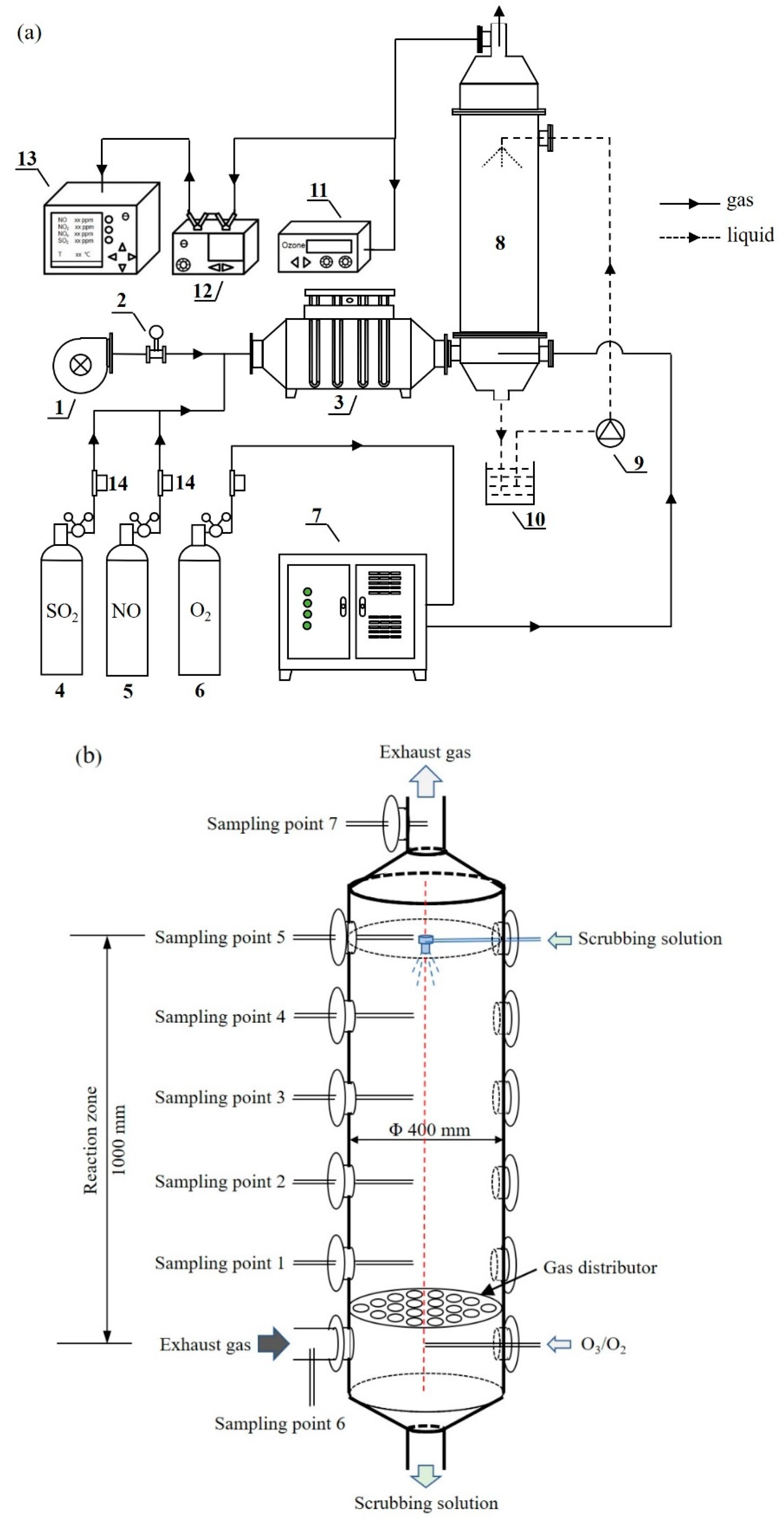
2. Materials and Methods

Normally the exhaust gas emitted from a marine diesel engine contained multiple kinds of pollutants. Under various loads, NO concentrations in exhaust gas was about in the range of 200–1500 ppm. When residual fuel (heavy fuel) with high sulfur content was used onboard, SO2 concentration was in the range of approximately 300–650 ppm. In our experiments, air was used as a carrier gas and supplied by a high-pressure blower. The targeted pollutants, NO and SO2, were supplied from gas cylinders and injected into the flue duct to mix with air. Note that the flow rates of simulated flue gases and initial targeted-pollutant concentrations were adjusted to the set values at room temperature at the beginning of the tests. The air flow was kept at 50 m3·h−1. Considering that the consumption amount of NO material gas would be very high when NO concentrations in simulated flue gas approached the highest level of diesel engines, an inlet NO concentration of 200 ppm was chosen as a basic condition in the experiments aiming to reduce test cost. As a validation test, a set of experiments with inlet NO concentration of 800 ppm and SO2 concentration of 400 ppm were carried out in the end.
The schematic diagram of our experimental setup was shown in Figure 2a. The reaction system consisted of gas supplies, reactor, and gas analyzers. The air flow was monitored by a vortex flow meter and could be controlled by adjusting the blower’s working frequency. The injection amount of NO and SO2 pure gases from separate cylinders were controlled through separated mass flow meters. After NO and SO2 gases were injected into the flue duct, the gas mixtures entered a duct heater to be heated to a set temperature (50–300 °C). O3 was produced by an ozone generator (Qingdao Guolin Co. Ltd., Qingdao, China) with O2 as a gas source. O2 with a flow rate of 0.5 m3·h−1 was supplied from an O2 cylinder to the ozone generator, and O3 yield was controlled through adjusting input power. The reactor was a typical spraying tower with a stainless nozzle at the top, and its structural diagram was shown in Figure 2b. The reactor was made of stainless steel, and its inner diameter was 400 mm. The simulated exhaust gas entered the reactor through the inlet at the bottom. There were 7 sampling points for measuring the flue gas temperature and flue gas components. The perpendicular distance between the two neighboring sampling points was 200 mm. An O3/O2 gas mixture was injected into the reactor through a separate pipe. A gas distributor was located above the inlet ports to mix the flue gas uniformly. A spraying nozzle was installed at the top of the reactor. The total volume of scrubbing solution was 14 L in each test. Scrubbing solution was pumped to the nozzle and the flow rate was about 1 L·min−1. A cyclic scrubbing mode was adopted, and the solution was collected in a tank. During the scrubbing process, the solution temperature could be kept at 50 °C through a thermostatic water bath. The pH value of the scrubbing solution in circulating tank was monitored by a pH meter and it could be maintained to the set value by adding 1 mol·L−1 HCl or 1 mol·L−1 NaOH solutions. O3 concentration in flue gas was measured by an ozone monitor (2B Technology Co., Boulder, CO, USA) with a sampling interval of 6 s. O2, NO, and NO2 concentrations in flue gas were monitored by a gas analyzer (MRU Co., Baden-Württemberg, Germany). Here, NOx concentrations referred to the sum of NO and NO2 concentrations. Each test proceeded for 30 min for 3 times, and the average values of gas concentrations were used to calculate NOx and SO2 removal efficiencies through the following equation:
η = [(CinCout)/Cin] × 100%
in which η was NOx or SO2 removal efficiency, Cin was the initial concentration of targeted pollutant (NOx or SO2) before injecting O3/O2 gases and/or scrubbing any solution, Cout was the concentration of targeted pollutant (NOx or SO2) after injecting O3/O2 gases and/or scrubbing any solution. Both Cin and Cout were measured at sampling point 7 as shown in Figure 2b.

3. Results

3.1. The Oxidation Performance of NO by Ozone Injection

3.1.1. Thermal Decomposition of Ozone

After ozone is injected in hot flue gas, a part of ozone will be decomposed to O2 during the mixing process of O3/O2 gas mixtures with hot flue gas. That is because ozone is thermodynamically unstable. Therefore, it is necessary to investigate the effect of flue gas temperature on ozone self-decomposition properties in the reaction tower before in-situ combining ozone injection with wet scrubbing.
Based on the home-made reaction system, the self-decomposition properties of ozone were investigated, and the results were shown in Figure 3. The flow rates of simulated flue gases and initial O3 concentrations were adjusted to the set values at room temperature at the beginning of the tests. The air flow was kept at 50 m3·h−1 measured at room temperature. Initial ozone concentrations in carrier gas were adjusted to 50, 100, 150, and 200 ppm, respectively. In each test, flue gas temperatures measured at sampling point 6 increased step by step from room temperature (25 °C) to 300 °C. Note that the volumes of flue gas increased obviously with the increase in flue gas temperature, then the flow rates and residence time in reaction tower changed correspondingly, as shown in Table 1.
The sampling points 1–5 correspond to various residence times of flue gas in the reaction zone. It could be seen from Figure 3 that ozone concentration decreased obviously with the increase in flue gas temperature. When flue gas temperature was 50 °C, only a very small part of ozone decomposed. There was a decreasing trend of ozone concentration with the increase in residence time. In addition, the changing trend seemed the same for different initial ozone concentrations. This result agreed well with the previous studies, which indicated that ozone would be decomposed obviously when flue gas temperature was higher than 150 °C [19,31]. As shown in Figure 3b, at sampling point 5, ozone concentrations were 161, 112, and 38 ppm when inlet flue gas temperatures were 200, 250, and 300 °C, respectively. This indicated that a large part of ozone would be decomposed when flue gas temperature was higher than 200 °C. Normally, the temperature of exhaust gas emitted from marine diesel engines was in the range of 180–300 °C, which could avoid the corrosion problem incurred by co-existing SOx in flue gas. Therefore, a nonnegligible part of ozone will be lost due to thermal decomposition if ozone is directly mixed with high-temperature marine exhaust gas. This will result in a very low oxidant utilization.
It could also be seen from Figure 3b that when inlet flue gas temperature was 300 °C, outlet ozone concentrations measured at different sampling points were more or less the same. This result was very interesting. Note that different sampling points corresponded to various residence times of flue gas in the reaction tower. Normally speaking, ozone concentration measured at different sampling points decreased obviously with the increase in residence time. However, our result did not exhibit the same trend. It was strange that ozone concentration sharply decreased from 200 ppm down to 43 ppm measured at sampling point 1, but it just further decreased to 38 ppm measured at sampling point 5. This result indicated that the majority of ozone molecules might be decomposed at the moment of injected ozone contacting with hot flue gas. The initial temperature of O3/O2 gas mixtures supplied from the ozone generator was at room temperature. When inlet flue gas temperature was 300 °C, there was a huge temperature difference between the inlet flue gas and inlet O3/O2 gas mixtures. Here, it was supposed that the rapid heating process was the main reason for ozone thermal decomposition. As shown in Figure 2b, there was a gas distributor located just under the sampling point 1. It was believed that injected ozone mixed uniformly with flue gas with the help of the gas distributor, and their temperature reached a stable state. Then ozone in flue gas only decomposed slightly although the flue gas temperature was still relatively high. This result also indicated that the thermal decomposition reaction occurred within a very short time (<1 s).

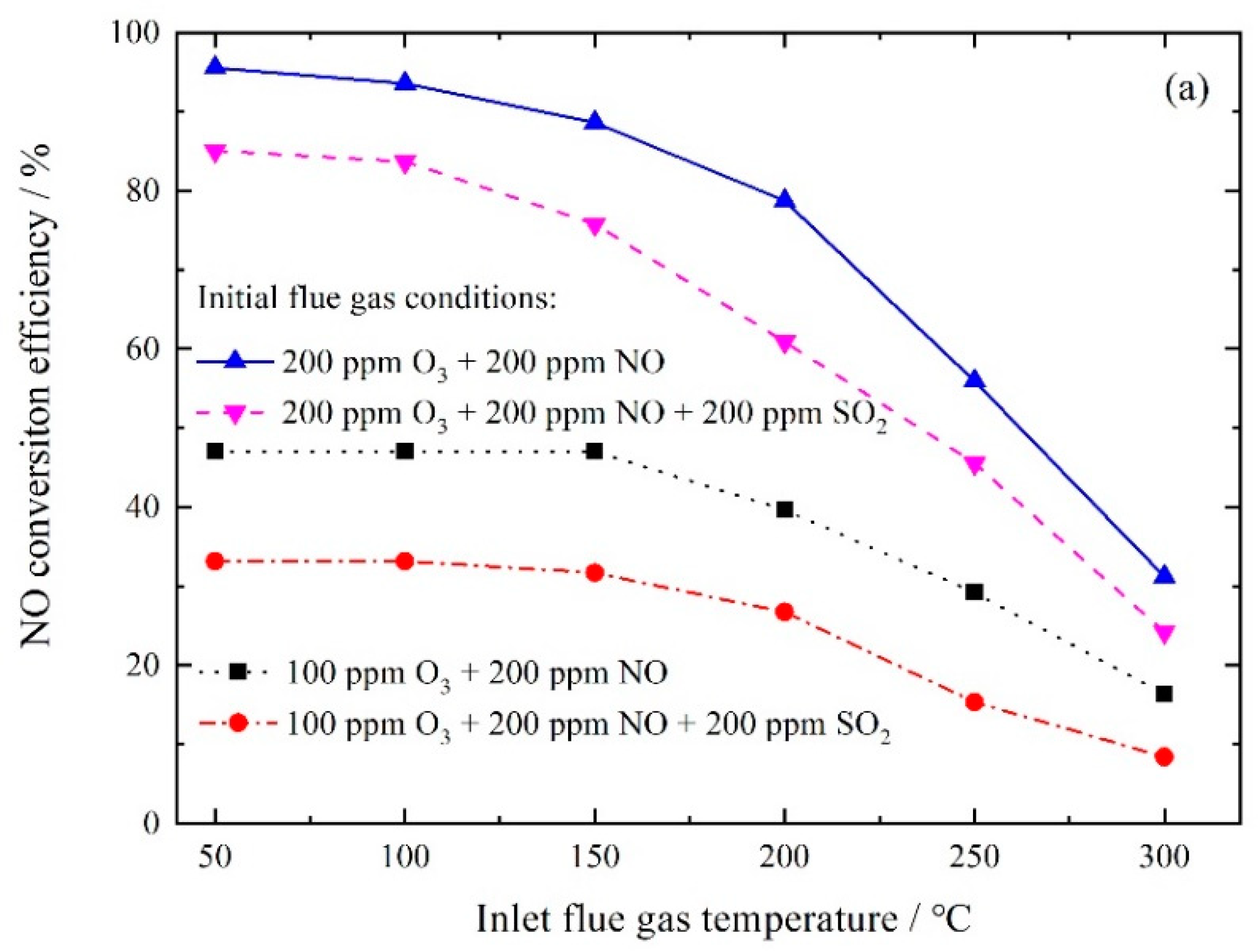
3.1.2. NO Conversion by Ozone Oxidation

The oxidative ability of ozone is very high, so O3 can oxidize NO to higher valence NOx easily. Based on the home-made reaction system, NO conversion performance by ozone oxidation was investigated, and the results were shown in Figure 4. Both initial NO and SO2 concentrations in simulated flue gas were adjusted to 200 ppm at room temperature. The injected O3 concentrations were adjusted to 100 or 200 ppm at room temperature. The concentrations of NO, NO2, and O3 were monitored at sampling point 5.
It could be seen from Figure 4a that when there was no co-existing SO2 in flue gas and flue gas temperature was relatively low, the injected ozone of 200 ppm could oxidize NO with a very high efficacy. NO conversion efficiency reached 95.5% when inlet flue gas temperature was 50 °C. However, NO conversion efficiency was only 31.2% when inlet flue gas temperature increased up to 300 °C. It was generally believed that oxidation of NO to NO2 occurred when O3/NO molar ratio was below 1.0, and further oxidation of NO2 to N2O5 occurred when O3/NO molar ratio was above 1.0. The previous study on the influence of reaction temperature indicated that the rate of NO2 formation was very fast and was basically not affected by the reaction temperature [19]. In our experiments, the residence time of flue gas in the reaction zone was calculated to be 4.63 s when flue gas temperature was heated to 300 °C. The low NO conversion efficiency implied that there was obvious competition between ozone thermal decomposition and NO oxidation by ozone. It was very possible that ozone thermal decomposition reaction occurred faster than NO oxidation reactions. As mentioned above, when inlet flue gas temperature was 300 °C, the majority of ozone was decomposed thermally rather than reacting with NO at the moment of O3 injecting into the reaction tower. This explained well why it was difficult to obtain a high NO oxidation efficiency when injecting ozone into hot flue gas.
As shown in Figure 3b, when inlet flue gas temperature was 300 °C and there was no initial NO in flue gas, only 38 ppm ozone was left in outlet flue gas. This meant that 162 ppm O3 had been lost due to thermal decomposition. However, when NO was introduced into the flue gas, NO conversion efficiency of 31.2% was obtained, as shown in Figure 4b. It seemed that the introduction of NO into flue gas could suppress the thermal decomposition of ozone to some extent. Since there was competition between ozone thermal decomposition and NO oxidation by ozone, both ozone thermal decomposition and NO oxidation proceeded simultaneously at the injection area. Furthermore, there might be another reason that a gas mixture of O3/O2 was injected into the reaction tower. As the ozone generator used in the experiments took O2 as gas source, the major part of O3/O2 gas mixture was O2. Thus, a small part of NO in flue gas could be oxidized to NO2 by O2 in the reaction tower.
As shown in Figure 4, co-existing SO2 imposed a negative effect on NO conversion efficiency. The previous studies reported that ozone could selectively oxidize NO when there was SO2 co-existing in the flue gas. Only a very small part (<0.2%) of SO2 could be oxidized to SO3 when flue gas temperature was 150 °C [17,19], but in our bench-scale experiments, when inlet O3 concentrations were 100 and 200 ppm, SO2 conversion efficiencies were 8.5% and 16.5%, respectively. It consumed more ozone with the increase in inlet ozone concentration. The result showed that co-existing SO2 consumed a nonnegligible ozone in gas phase reactions. There was an obvious competition between NO and SO2 to be oxidized by ozone. Therefore, it was necessary to take measures to further improve the selective oxidation of NO over SO2.

3.2. Simultaneous Removal of NO and SO2 by In-Situ Combination of Ozone Injection with Wet Scrubbing

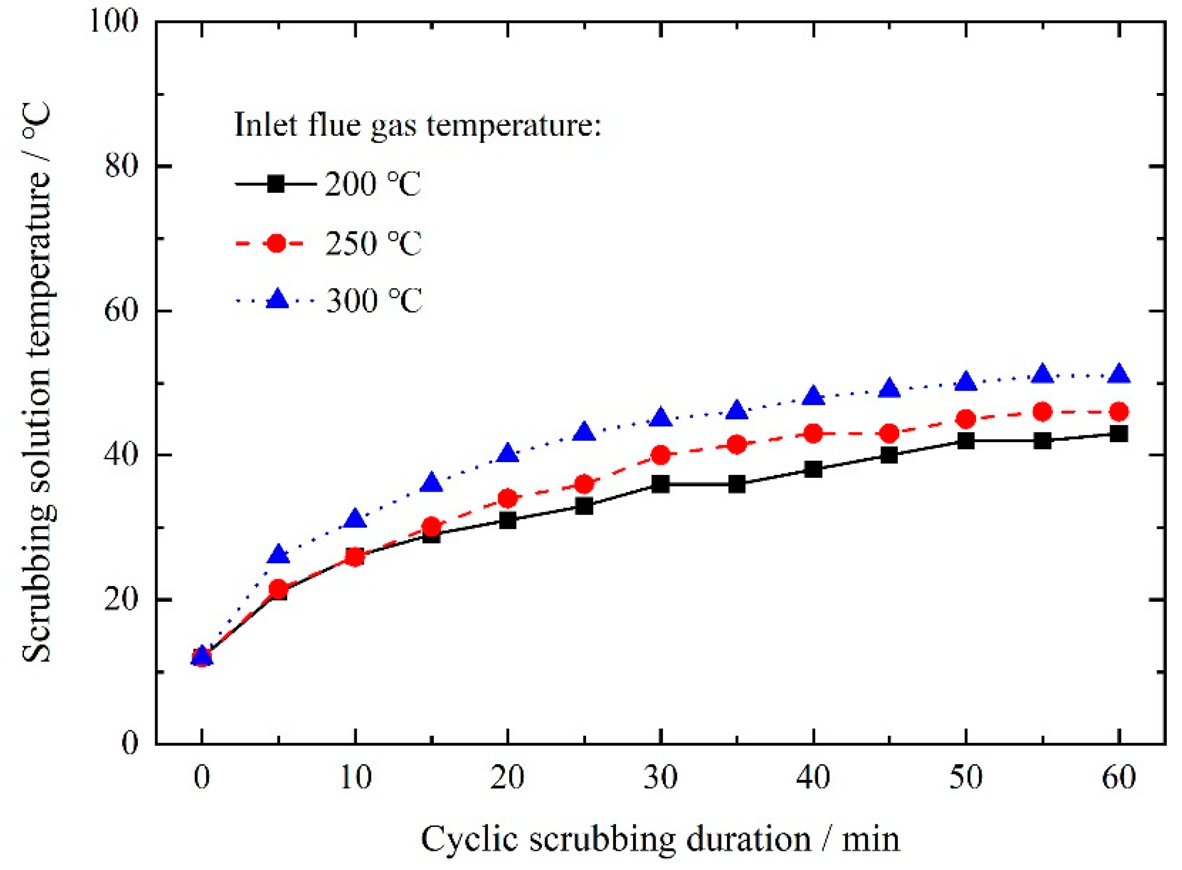
3.2.1. Effect of Wet Scrubbing on Solution Temperature

Firstly, the effects of wet scrubbing on cyclic scrubbing solution temperatures were investigated based on our self-built reaction system, and the results were shown in Figure 5. Here, 30 L deionized water was used as cyclic scrubbing solution. Initial solution temperatures were at room temperature, and the thermostat water bath was switched off. The flow rate through the spraying nozzle was about 1 L·min−1. It can be seen from Figure 5 that cyclic scrubbing solution temperature increased gradually, and then reached a stable state. When inlet flue gas temperatures were 200, 250, and 300 °C, cyclic scrubbing solution temperatures after scrubbing for 60 min were 43, 46, and 51 °C, respectively. At the same time, outlet flue gas temperatures measured at sampling point 7 were 51, 56, and 59 °C, respectively. It implied that flue gas temperature had been controlled to a very low level during the wet scrubbing process. This result illustrated that the wet scrubbing process could help to suppress the thermal decomposition of ozone efficiently.

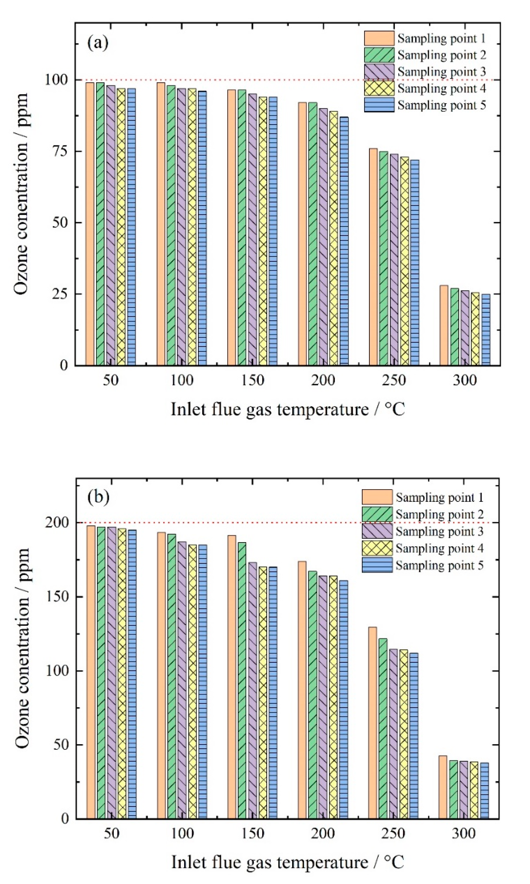
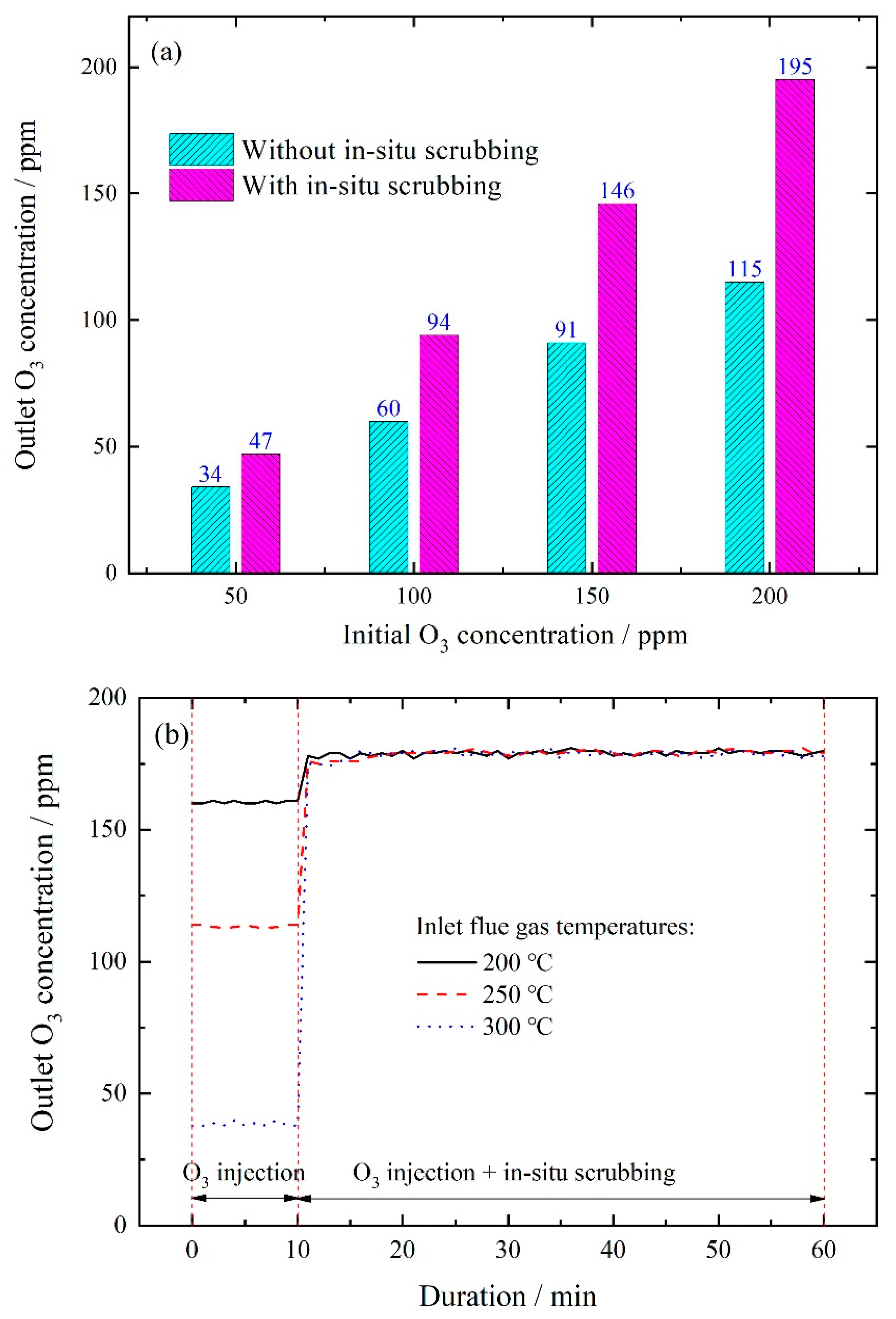
3.2.2. Effect of Wet Scrubbing on Outlet Ozone Concentration

It was normal that the contact of spraying solution and flue gas in reaction tower could decrease flue gas temperature greatly. Furthermore, the effect of wet scrubbing on outlet ozone concentrations was examined, and the results were shown in Figure 6. An amount of 14 L deionized water was used as scrubbing solution, and the cyclic solution temperature was kept at 50 °C by a water bath at the beginning. Initial ozone concentrations were adjusted to 50–200 ppm at room temperature. Inlet flue gas temperatures were heated to 200, 250, and 300 °C, respectively. Since there were no targeted pollutants in inlet flue gas, there was no need to maintain solution pH to a set value by adding any additives during the cyclic scrubbing process.
As shown in Figure 6a, when inlet flue gas temperature was 250 °C, outlet ozone concentrations approached the initial levels with the combination of in-situ scrubbing. When initial ozone concentration was 200 ppm, outlet ozone concentration was 195 ppm with only a 2.5% decrement. This result well demonstrated that in-situ scrubbing was vital to suppress the thermal decomposition of ozone, which made it possible for more ozone to be left to oxidize NO in the reaction tower. It also could be seen from Figure 6b that when flue gas temperature was 300 °C, outlet ozone concentration increased sharply from 40 to 180 ppm after the introduction of in-situ wet scrubbing with deionized water. During the cyclic scrubbing process, outlet ozone concentration changed slightly. The result also showed that there was no obvious effect of scrubbing solution on outlet ozone concentration, indicating that ozone would not be reduced by the scrubbing solution through physical absorption or chemical reactions. It confirmed that in-situ combination of ozone injection and wet scrubbing effectively suppressed the thermal decomposition of ozone. Thus, it was of great potential to improve the utilization of ozone oxidants greatly in the denitrification process.

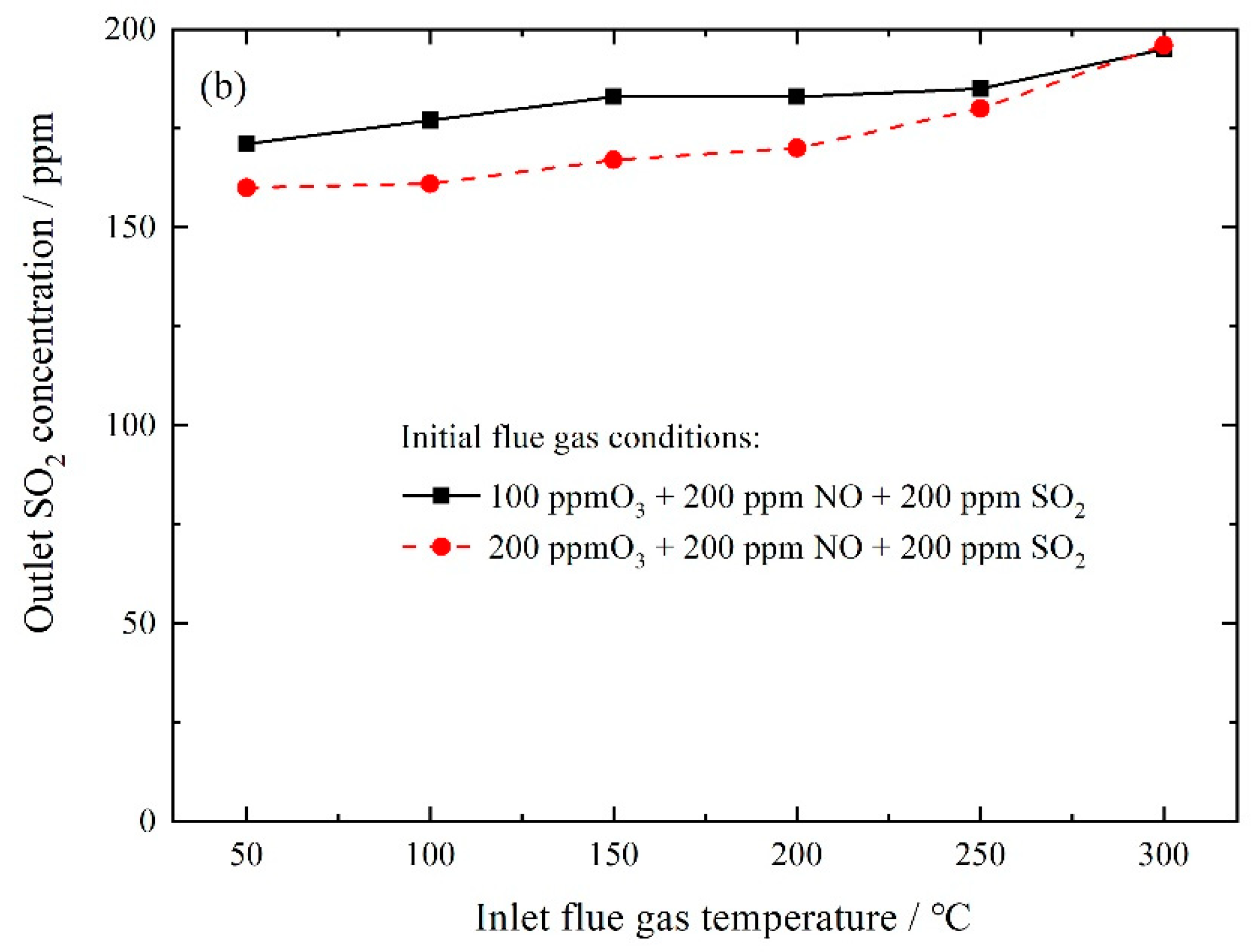
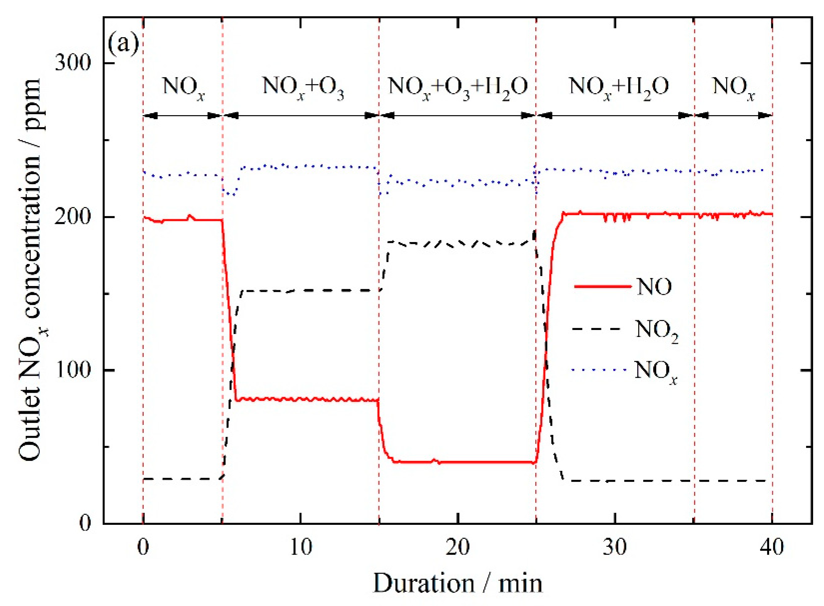
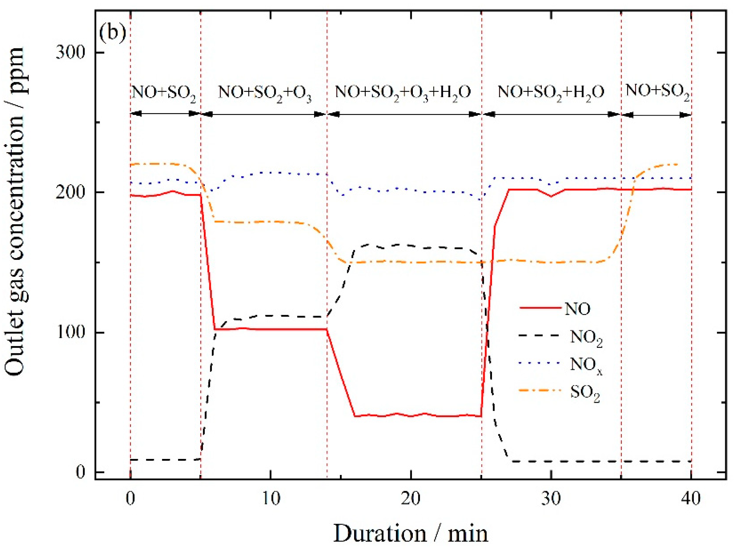
3.2.3. NO Oxidation and SO2 Removal by In-Situ Ozone Oxidation and Wet Scrubbing

Experiments were performed to oxidize NO by in-situ combination of ozone oxidation and wet scrubbing, and the results were shown in Figure 7. NO concentration in inlet flue gas was adjusted to 200 ppm at room temperature at the beginning. Since there was about 21% O2 in carrier air gas, there was 20–30 ppm NO2 in the initial flue gas due to the oxidation of NO by O2 during the NO injection process. An amount of 14 L deionized water was used as scrubbing solution. When SO2 was introduced in inlet flue gas, the absorption of SO2 lowered the pH of scrubbing solution obviously during the cyclic scrubbing process. This required supplementing alkaline solution continuously to maintain cyclic scrubbing solution pH to a set value. Considering that there were no other oxidative additives introduced in the scrubbing solution, the introduction of alkaline species would impose a great effect on SO2 absorption. Therefore, pH value of cyclic scrubbing solution was not maintained in these tests. The cyclic solution temperature was kept at 50 °C by a water bath at the start. Initial O3 and SO2 concentrations in flue gas were adjusted to 200 and 220 ppm, respectively, at room temperature when used. The temperatures of flue gas before entering the reaction tower were maintained at 250 °C throughout the tests.
As shown in Figure 7a, outlet NO concentration decreased quickly from 200 to 81 ppm, and outlet NO2 concentration increased from 29 to 152 ppm after injection of 200 ppm ozone into the reaction tower at 5th min. Then NO concentration further decreased to 40 ppm, and NO2 concentration increased to 182 ppm after the introduction of in-situ wet scrubbing of deionized water. As expected, in-situ combination of ozone injection and wet scrubbing improved NO oxidation by ozone efficiently.
As shown in Figure 6b, when inlet flue gas temperature was 250 °C and initial ozone concentration was 200 ppm, outlet ozone concentration was about 195 ppm. However, one could see from Figure 7a that NO conversion efficiency was only 80% with in-situ combination of ozone injection and wet scrubbing, which was a slightly lower than the expectation. The solubility of NO2 was much higher than that of NO: a part of NO2 reacted in water to form HNO3 and HNO2 through the following equations [32]. During the NO2 absorption process, NO was formed and escaped from scrubbing solution. This might be the reason for a relatively lower NO conversion efficiency. At the 25th min, ozone injection was stopped, and outlet NO concentration quickly increased to about 202 ppm. It showed that little NO could be removed by wet scrubbing deionized water due to extremely low solubility of NO in water.
2NO2(g) ↔ N2O4 (g)
NO2(g) ↔ NO2(l)
N2O4 (g) ↔ N2O4 (l)
2NO2(l) + H2O(l) ↔ HNO3(l)+ HNO2(l)
N2O4 (l) + H2O(l) ↔ HNO3(l)+ HNO2(l)
3HNO2(l) ↔ HNO3(l) + 2NO(l) + H2O(l)
NO(l) ↔ NO(g)
Figure 7b illustrated the effects of co-existing SO2 on NO oxidation and NOx removal performance during the reaction process. At the beginning, initial NO and SO2 concentrations in inlet flue gas were adjusted to about 200 and 220 ppm, respectively. After the introduction of O3/O2 mixture gases at the 5th min, outlet SO2 concentration obviously decreased to 179 ppm, while outlet NO concentration decreased from 198 to 102 ppm and outlet NO2 concentration increased from 9 to 98 ppm. Some previous lab-scale studies reported that ozone could selectively oxidize NO rather than SO2 when O3/NO molar ratio was less than 1 [19]. However, in our bench-scale experiments, the selectivity of NO oxidation by ozone was not high enough, and co-existing SO2 imposed an apparent negative effect on NO oxidation. This result confirmed that there were competition oxidation reactions between NO and SO2 with ozone. Especially when O3/O2 mixture gases were injected out from the injection pipe, locally high-concentration of O3 existed near the injection area. This led to some side reactions through Equations of ((2),(3),(14)).
SO2 + O3 → SO3 + O2
Since the oxidation of SO2 consumes a certain fraction of O3, resulting in a low utilization of ozone, such side reactions should be avoided as far as possible. For practical application, it might be necessary to take some measures to improve the local high-level ozone distribution problem. For example, one could adopt a multiple-pipe injection method and/or lower O3 concentration by introducing extra air to mix with O3/O2 mixture before it was injected into the reaction tower.
At the 14th min, in-situ scrubbing of deionized water was introduced: outlet NO concentration decreased further from 102 to 40 ppm while outlet NO2 concentration increased from 98 to 162 ppm. Outlet SO2 concentration only decreased from 179 to 150 ppm mainly due to physicochemical absorption by scrubbing solution. The results showed that in-situ scrubbing could not only improve NO oxidation through suppressing the thermal decomposition of ozone but also improve NO oxidation selectivity. Since the solubility of SO2 in water was very high, more SO2 was removed through the hydrolysis:
SO2(g) ↔ SO2(l)
SO2(l) ↔ SO2(l)
SO2(l) + H2O(l) ↔ H2SO2(l)
H2SO3(l) ↔ H+ + HSO3
At the 20th min, the injection of O3 was stopped, and outlet SO2 concentration changed slightly. This suggested that SO2 was removed mainly through the physicochemical absorption by wet scrubbing solution. After stopping ozone injection, outlet NO and NO2 concentrations recovered to the initial level quickly.
The cyclic scrubbing was stopped at the 30th min, and outlet SO2 returned to the initial level quickly. The results showed that in-situ combination of ozone injection with wet scrubbing could improve both ozone utilization and NO oxidation selectivity simultaneously, and co-existing SO2 imposed little effect on NO oxidation by O3.

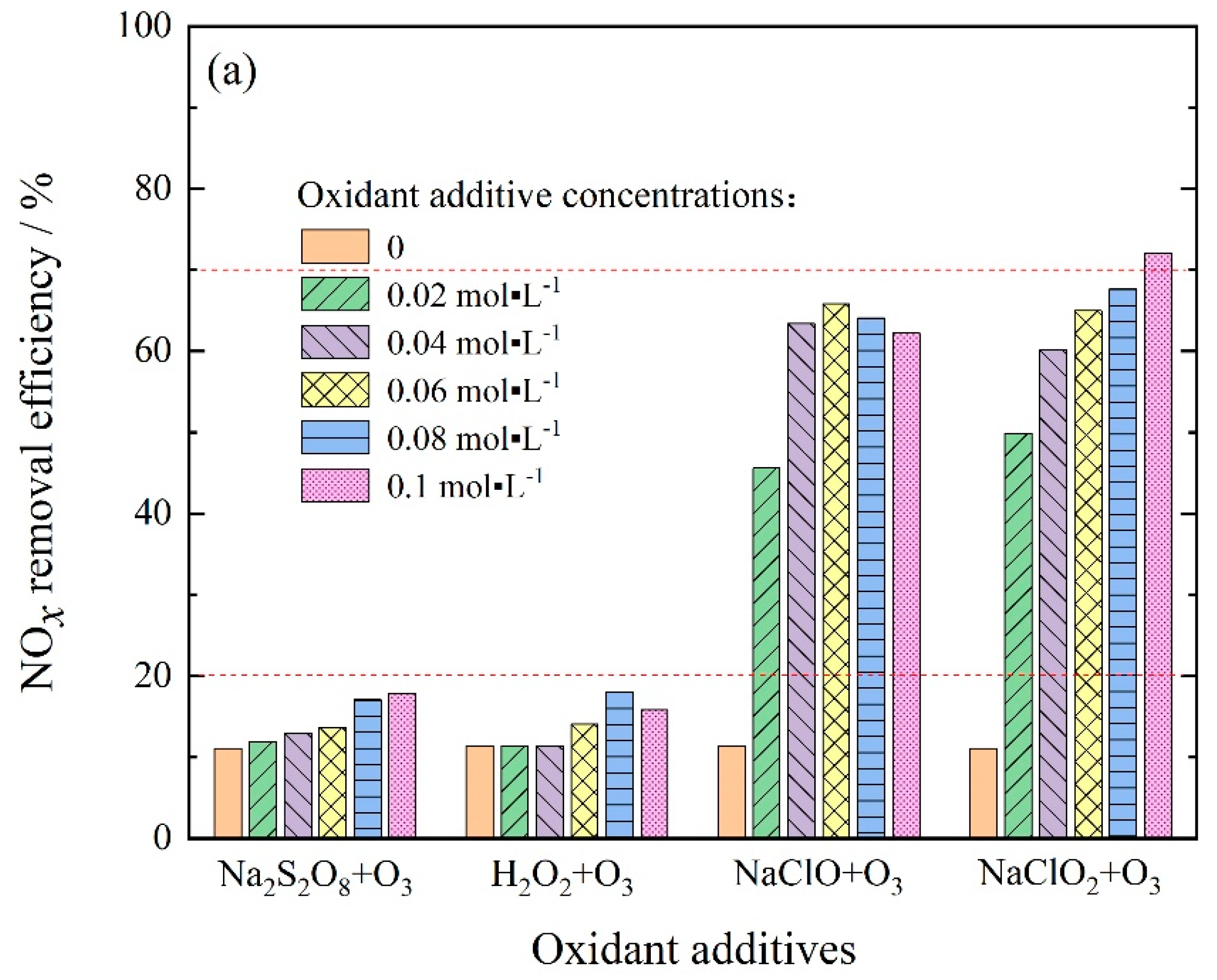
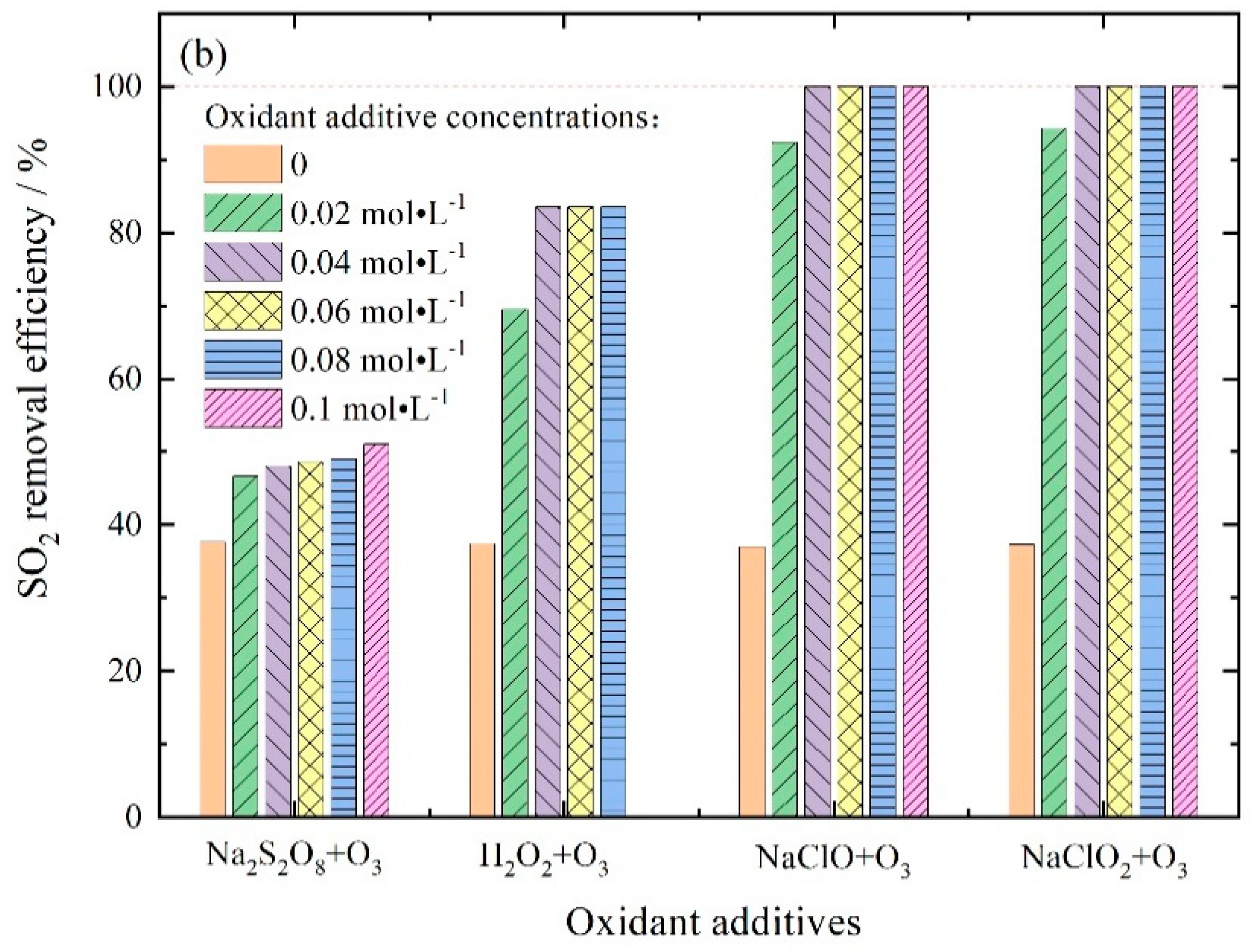
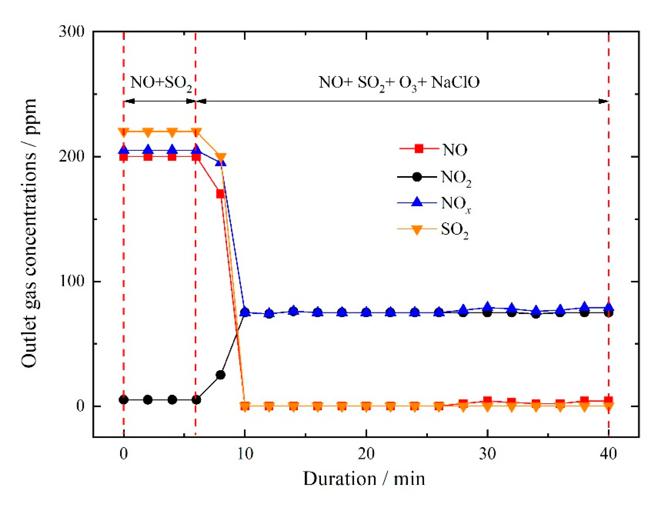
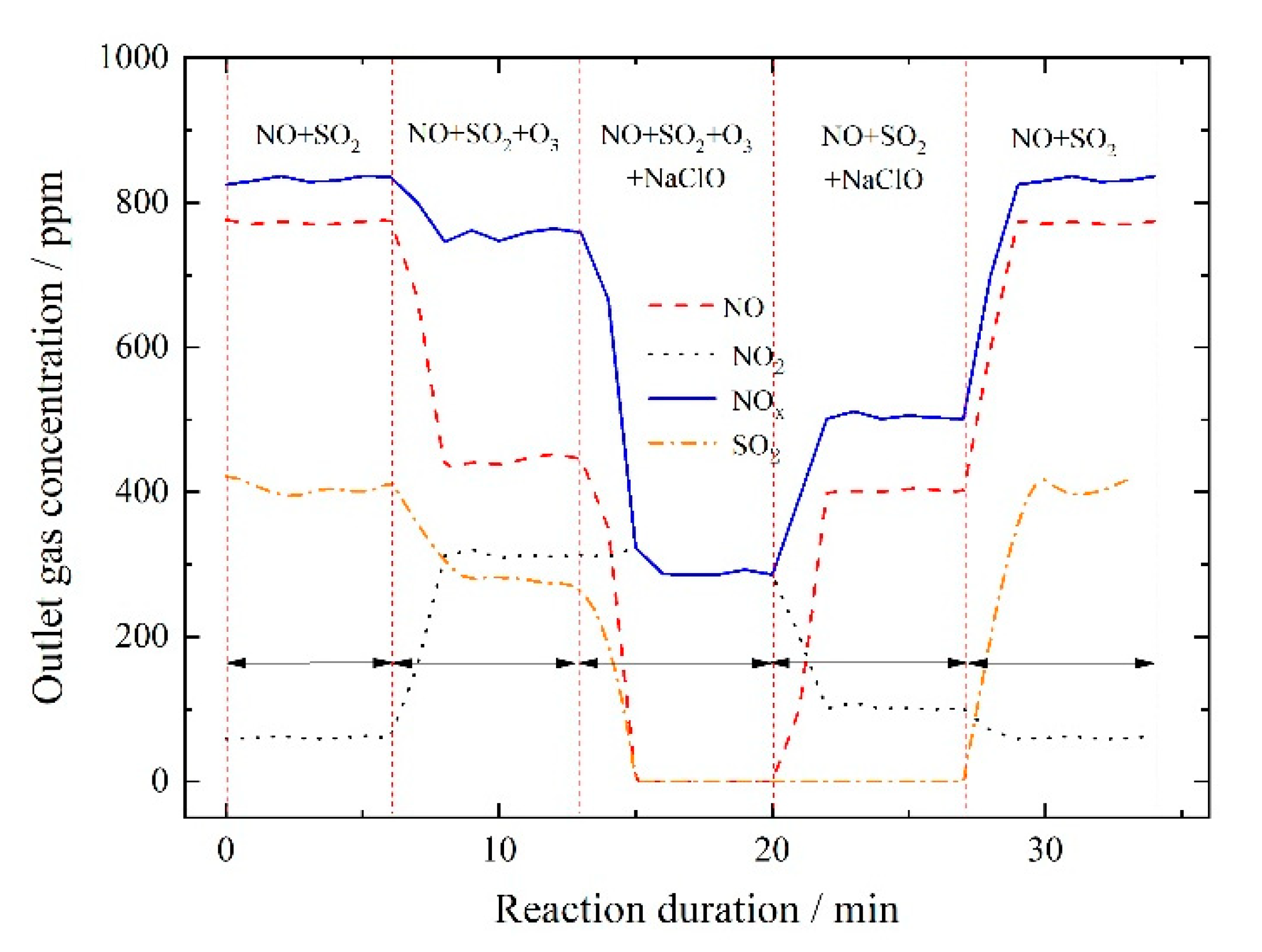
3.2.4. NOx and SO2 Removal by Ozone Injection and In-Situ Scrubbing with Oxidant Additives

The above-mentioned experiments illustrated that in-situ combination of ozone injection and wet scrubbing could oxidize NO to NO2 effectively, but it still required to take some measures to remove NO and SO2 from flue gas with a high efficacy. In the tests, O3/NO molar ratio was kept at 0.5 in order to achieve a low energy consumption for generating ozone onboard. Aiming to obtain a high NOx removal efficiency, it was necessary to introduce some oxidant additives into scrubbing solution to combine with ozone to oxidize NO, and then to remove NOx and SO2 simultaneously. This was an obvious advantage of this approach that we proposed. Here, effects of several common oxidant additives on NO and SO2 removal performance were investigated preliminarily, and the results were presented in Figure 8.
The air flow was kept at 50 m3·h−1 measured at room temperature. NO, SO2, and O3 concentrations in inlet flue gas were adjusted to 200, 220, and 100 ppm, respectively, at the beginning. The temperature of flue gas before entering the reaction tower was maintained at 250 °C during the whole tests. An amount of 14 L deionized water was used as scrubbing solution, and the solution pH was maintained to 6 by adding 1 mol·L−1 NaOH solution continuously during the whole reaction process. The cyclic solution temperature was kept at 50 °C by a water bath from the beginning. Four kinds of common oxidants—NaClO, Na2S2O8, H2O2, and NaClO2—were chosen to add into scrubbing solution to work with ozone. The oxidative power of these oxidants was strong enough, and a large amount of interests had been attracted from numerous researchers to investigate their NO removal performance through wet scrubbing [9,10,11,12]. The previous research indicated that these four kinds of oxidative additives that we chose could oxidize and remove NO with a high efficiency. In the following tests, initial concentrations of oxidant additives in solutions were in the range of 0–0.1 mol·L−1.
It could be seen from Figure 8a that NOx removal efficiency was about 11% when ozone was in-situ combined using pH-buffered scrubbing solution with no oxidative additives. This indicated that online supplementing of alkaline species was in favor of absorbing NOx from flue gas.
Generally, oxidants such as Na2S2O8 and H2O2 must be activated by heat, UV, or metal ions for generating strong oxidant species (free radicals) to effectively oxidize NO to higher valance NOx, thus obtaining a high NOx removal efficiency [12,33,34]. In our experiments, ozone was injected in-situ to contact with scrubbing solution droplets. As shown in Figure 8a, NOx removal efficiencies for Na2S2O8 + O3 and H2O2 + O3 systems were below 20%. This implied that ozone could not activate Na2S2O8 and H2O2 efficiently during the scrubbing process.
When NaClO or NaClO2 solution was cyclic scrubbed in the reaction tower with ozone injection, a much higher NOx removal efficiency could be obtained. As shown in Figure 8a, with the increase in NaClO2 concentration from 0 to 0.1 mol·L−1, NOx removal efficiency increased from 11% to 72%. As for NaClO, with the increase in NaClO2 concentration from 0 to 0.06 mol·L−1, NOx removal efficiency increased from 11% to 65.8%. However, NOx removal efficiency decreased down to 62.2% when further increasing NaClO2 concentration to 0.1 mol·L−1. This illustrated that in-situ combination of ozone oxidation and wet scrubbing absorption using NaClO or NaClO2 as extra oxidative additives apparently improved NOx removal performance. Meanwhile, a complete removal of SO2 was reached when NaClO or NaClO2 concentration was higher than 0.04 mol·L−1.
Though the oxidative power of NaClO2 was normally much higher than that of NaClO for wet oxidation of NO [35], NOx removal efficiency approached to each other when additive concentration was 0.04 mol·L−1 used in our experiments. Considering that the reagent costs of NaClO2 was much higher than that of NaClO, and for ocean-going vessels, there was another possible way to obtain NaClO through seawater electrolysis [36]. Thus, it was believed that ozone injection combined with in-situ scrubbing NaClO solution would be a good choice for marine application for simultaneous removal of NO and SO2 from exhaust gas.
Most of the previous studies on simultaneous removal of SO2 and NO from simulated flue gas by using NaClO solution were based on lab-scale reactors, together with an extremely high liquid-gas ratio and gas residence time in reactor. NO oxidation rate rather than NOx removal efficiency was used to characterize the denitration performance. For instance, Mondal et al. studied NO oxidation by wet scrubbing using NaClO solution. Under their optimal conditions, maximum SO2 removal efficiency and NO conversion rate were 100% and 92%, respectively, at 40 °C, initial NaClO solution pH 5.8, and 0.01 mol·L−1 NaClO concentration [37]. The similar results implied that it was difficult to obtain a high NOx removal efficiency by wet scrubbing using NaClO solution alone due to the relatively low solubility of NO and NO2. Thus, it was necessary to take measures to further improve NOx absorption performance of NaClO solution. Yang et al. proposed to enhance NO oxidation performance by introducing online UV irradiation, in which radical species were generated to oxidize NO in an efficient way. However, their NOx removal performance was still not high enough [38]. In our experiments, a very high NOx removal efficiency was achieved through in-situ combining ozone injection and wet scrubbing based on a bench-scale reactor.
For illustrating the reaction process of in-situ combining ozone oxidation and wet scrubbing absorption, the changes of outlet gas concentrations with the reaction duration were presented in Figure 9. Here, initial NaClO concentration in solution was 0.04 mol·L−1. NO, SO2, and O3 concentrations in inlet flue gas were adjusted to 200, 220, and 100 ppm, respectively, at room temperature at the beginning. It can be seen from Figure 9 that after the introduction of ozone injection and in-situ wet scrubbing at the same time, both outlet NO and SO2 concentration decreased sharply down to 0 ppm. Outlet NO2 concentration increased from 5 to 75 ppm. A complete removal of SO2 and NOx removal efficiency of 63.4% were achieved simultaneously. The addition of NaClO in scrubbing solution enhanced NO oxidation and NO2 absorption greatly.
Simultaneous removal of high-concentration SO2 and NO by in-situ combination of ozone injection and wet scrubbing was also investigated, and the result was shown in Figure 10. Here, initial NaClO concentration in solution was still 0.04 mol·L−1, while NO, SO2, and O3 concentrations in inlet flue gas were adjusted to 800, 400, and 400 ppm, respectively, at room temperature at the beginning. The air flow was kept at 50 m3·h−1 measured at room temperature. The temperature of flue gas before entering the reaction tower was maintained at 250 °C throughout the tests. At the start, initial NO concentration measured at sampling point 7 was about 770 ppm rather than 800 ppm, because with the increase in flue gas temperature from room temperature to 250 °C, NO was oxidized to NO2 by O2 in carrier air gas.
The result showed that after the introduction of 400 ppm ozone, outlet NO concentration decreased quickly down to about 440 ppm, while outlet SO2 concentration decreased slightly down to about 280 ppm. With the cyclic scrubbing of 0.04 mol·L−1 solution, both outlet NO and SO2 concentration decreased sharply down to 0 ppm. A complete removal of SO2 and NOx removal efficiency of 65.5% were achieved simultaneously. However, when ozone injection was shut off, outlet NO concentration increased sharply from 0 to 405 ppm, while NO2 decrease from 286 ppm down to 101 ppm. At that moment, NOx and SO2 removal efficiencies were 39% and 100%. This result showed that both ozone and NaClO played important roles in NO oxidation and absorption in our reaction system. As long as the molar ratio of O3 to ozone was kept at 0.5, higher inlet NO concentration did not change NOx removal efficiency. Because ozone could efficiently oxidize a large part of NO to NO2, NaClO in solution could oxidize the left part of NO and absorb NOx in an efficient way.

4. Discussion

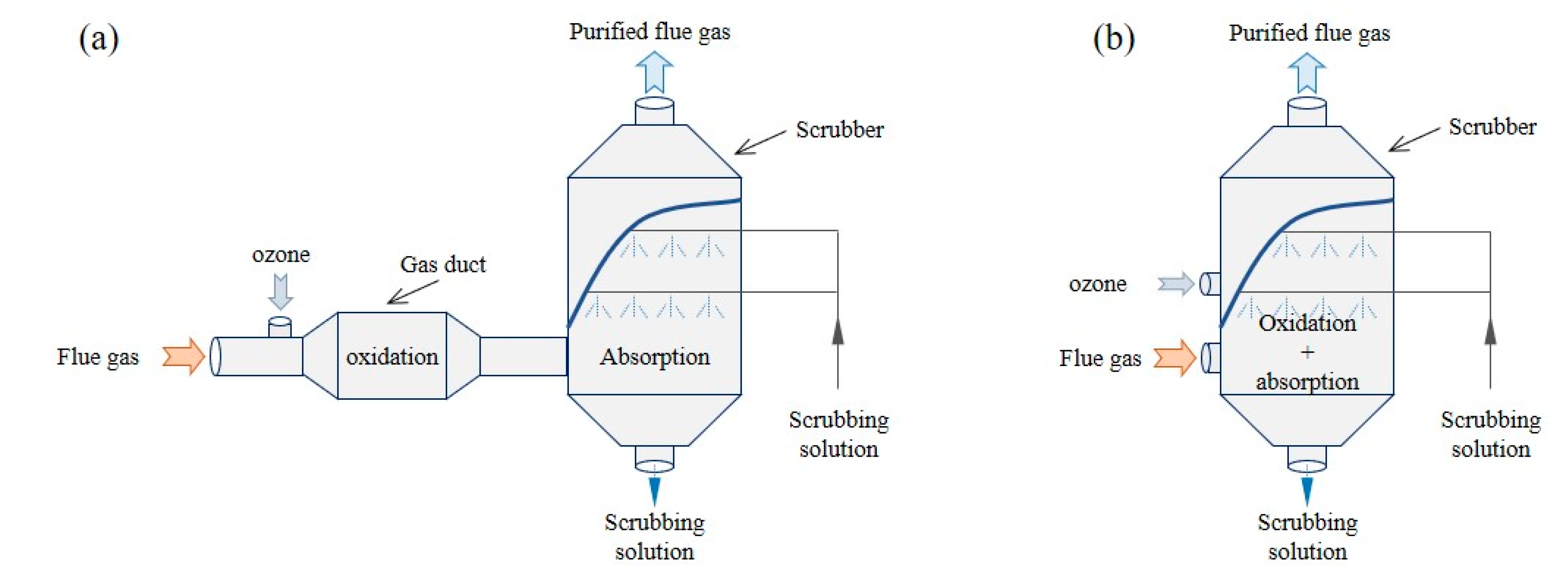
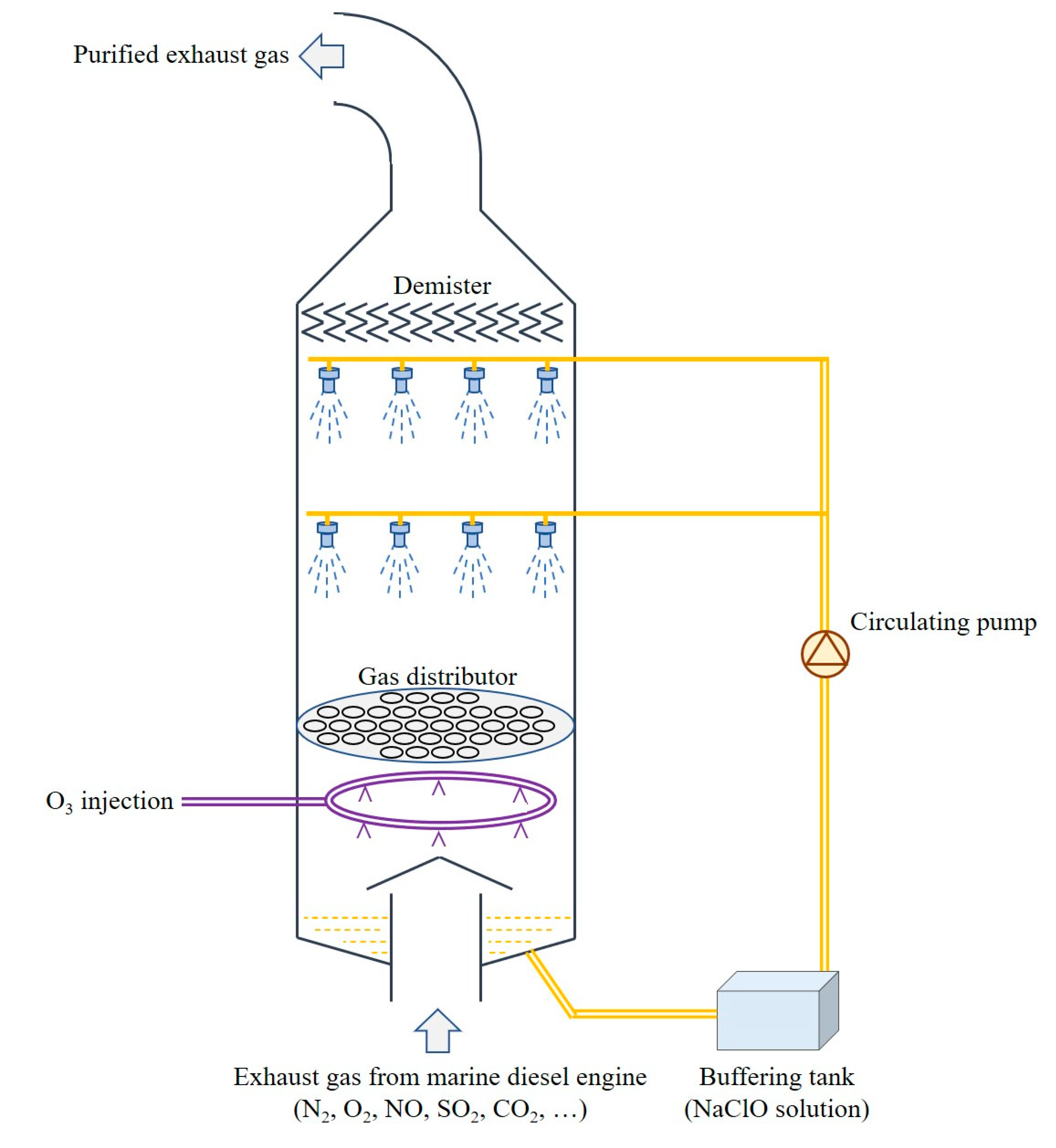
4.1. New Concept of an Integrated System

The conventional solution for removal of NO and SO2 from marine exhaust gas was the combination of wet scrubbing and SCR in series, but this method was difficult to realize due to the limited engine space and complicated flue gas conditions. Ozone was a kind of efficient NO oxidant, but the two-stage method usually required O3/NO molar ratio higher than 2, and it was difficult to obtain a high oxidant utilization due to serious thermal decomposition of ozone. Here, we proposed the method of combing ozone injection with in-situ wet scrubbing oxidative solution to complete the simultaneous removal of NO and SO2. The process diagram was shown in Figure 11, in which ozone was injected into the scrubbing tower directly. The in-situ spraying solution cooled flue gas temperature quickly below 100 °C, which was beneficial to suppress the thermal decomposition of ozone, further improving the oxidant utilization greatly. The molar ratio of O3/NO was kept much lower than 1 in order to reduce the usage of ozone and to reduce the electricity consumption by ozone generating system. Additional oxidative species (such as NaClO) were used to collaborate with ozone to oxidize NO, and absorb NOx and SO2 in an efficient way. This new method was in favor of exploiting the advantages of ozone oxidation and wet scrubbing processes, making it more practical for industrial applications.

4.2. Application Prospect of the Integrated System

Since 1 January 2020, the limit on sulfur content in marine fuel oil has been lowered greatly from 3.5 down to 0.5 wt.%. Instead of adopting low sulfur fuel oil, thousands of sets of wet scrubbers have been installed onboard in recent years. Most of the scrubbers were based on open-loop mode, which made use of the alkalinity of seawater to remove SOx from marine exhaust gas with a high efficacy. Once the price differences between high-S and low-S fuel oils were high enough, the shipowners would be paid back within 2–5 years. Generally, it would cost a couple of million dollars to install an open-loop wet DeSOx systems onboard an ocean-going vessel. At present, such a wet scrubber could not remove any NOx from marine exhaust gas due to the ultralow solubility of NO in water.
It was known that it was hard to abate NOx emission through improving the performance of diesel engine itself. To date, stringent regulations on NOx emissions have come into force in some international emission control areas. The demands for simultaneous removal of SOx and NOx from marine exhaust gas became increasingly imperious. The integrated system that we proposed could be easily realized by combining an ozone generating device with a wet DeSOx scrubber. Though such an integrated system required extra equipment and operation cost, it was of great potential to remove SOx and NOx simultaneously with a high efficiency. Compared with other solutions, such as low sulfur oil + SCR, low sulfur oil + EGR, and wet scrubber + SCR, our integrated system had some advantages: high removal efficiency, low investment cost, and easy operation. For future application, there were still some issues to be further explored with this integrated system, in order to reduce energy consumption and the secondary pollution risk. However, it was believed that in-situ combination of ozone oxidation and wet scrubbing for simultaneous removal of SOx and NOx, even as a transitional solution, was of great potential for marine application.

5. Conclusions

A new process of in-situ combining ozone injection and wet scrubbing oxidative solution was proposed for simultaneous removal of NO and SOx from marine exhaust gas. The results showed that in the absence of in-situ wet scrubbing, a large amount of ozone was thermally decomposed when it was directly injected into hot flue gas, and co-existing SO2 consumed a nonnegligible amount of ozone during the mixing process. The introduce of in-situ wet scrubbing not only suppressed the thermal decomposition of ozone, further improving the oxidant utilization, but also improved NO oxidation over SO2. The addition of other oxidants into scrubbing solution could simultaneously remove NO and SO2 in an efficient way. When O3/NO molar ratio was 0.5 and initial NaClO concentration in solution was 0.04 mol·L−1, NOx removal efficiency of 63.4% and a completed removal of SO2 could be achieved at the same time. The integrated system had some obvious advantages such as compact structure, low oxidant usage, high pollutant removing efficiency, and easy accessibility of oxidants. This offered useful reference for marine multi-pollutant abatement technologies.

Author Contributions

Conceptualization, validation, supervision, investigation, writing—original draft, writing—review and editing, project administration, funding acquisition, Z.H.; investigation, validation, formal analysis, T.Z. and J.W.; methodology, J.D.; data analysis, Y.D.; project administration, funding acquisition, X.P. All authors have read and agreed to the published version of the manuscript.

Funding

This research was funded by National Natural Science Foundation of China, grant number 51779024, and Fundamental Research Funds for the Central Universities, grant number 3132019330.

Conflicts of Interest

The authors declare no conflict of interest. The funders had no role in the design of the study; in the collection, analyses, or interpretation of data; in the writing of the manuscript, or in the decision to publish the results.

References

  1. Ma, D.; Ma, W.; Jin, S.; Ma, X. Method for Simultaneously Optimizing Ship Route and Speed with Emission Control Areas. Ocean Eng. 2020, 202, 107170. [Google Scholar] [CrossRef]
  2. Moldanova, J.; Fridell, E.; Popovicheva, O.; Demirdjian, B.; Tishkova, V.; Faccinetto, A.; Focsa, C. Characterisation of Particulate Matter and Gaseous Emissions from a Large Ship Diesel Engine. Atmos. Environ. 2009, 43, 2632–2641. [Google Scholar] [CrossRef]
  3. Brynolf, S.; Magnusson, M.; Fridell, E.; Andersson, K. Compliance Possibilities for the Future ECA Regulations through the Use of Abatement Technologies or Change of Fuels. Transp. Res. Part D Transp. Environ. 2014, 28, 6–18. [Google Scholar] [CrossRef]
  4. Lack, D.A.; Corbett, J.J.; Onasch, T.; Lerner, B.; Massoli, P.; Quinn, P.K.; Bates, T.S.; Covert, D.S.; Coffman, D.; Sierau, B.; et al. Particulate Emissions from Commercial Shipping: Chemical, Physical, and Optical Properties. J. Geophys. Res. Atmos. 2009, 114, D00F04. [Google Scholar] [CrossRef] [Green Version]
  5. Zhu, Y.; Tang, X.; Li, T.; Ji, Y.; Liu, Q.; Guo, L.; Zhao, J. Shipboard Trials of Magnesium-Based Exhaust Gas Cleaning System. Ocean Eng. 2016, 128, 124–131. [Google Scholar] [CrossRef]
  6. Guan, B.; Zhan, R.; Lin, H.; Huang, Z. Review of State of the Art Technologies of Selective Catalytic Reduction of NOx from Diesel Engine Exhaust. Appl. Therm. Eng. 2014, 66, 395–414. [Google Scholar] [CrossRef]
  7. Wang, Z.; Zhou, S.; Feng, Y.; Zhu, Y. Research of NOx Reduction on a Low-Speed Two-Stroke Marine Diesel Engine by Using EGR (Exhaust Gas Recirculation)–CB (Cylinder Bypass) and EGB (Exhaust Gas Bypass). Int. J. Hydrogen Energy 2017, 42, 19337–19345. [Google Scholar] [CrossRef]
  8. Ni, P.; Wang, X.; Li, H. A Review on Regulations, Current Status, Effects and Reduction Strategies of Emissions for Marine Diesel Engines. Fuel 2020, 279, 118477. [Google Scholar] [CrossRef]
  9. Han, Z.; Liu, B.; Yang, S.; Pan, X.; Yan, Z. NOx Removal from Simulated Marine Exhaust Gas by Wet Scrubbing Using NaClO Solution. J. Chem. 2017, 2017, 9340856. [Google Scholar] [CrossRef] [Green Version]
  10. Han, Z.; Lan, T.; Han, Z.; Yang, S.; Dong, J.; Sun, D.; Yan, Z.; Pan, X.; Song, L. Simultaneous Removal of NO and SO2 from Exhaust Gas by Cyclic Scrubbing and Online Supplementing pH-Buffered NaClO2 Solution. Energy Fuels 2019, 33, 6591–6599. [Google Scholar] [CrossRef]
  11. Xie, W.X.; Xu, C.W.; Zhang, J.; Liu, Y.X.; Xi, J.F.; Lv, J.H.; Gu, Z.Z. Simultaneous Removal of SO2 and NO from Flue Gas Using H2O2/Urea Activated by Vacuum Ultraviolet Light in a Pilot-Scale Spraying Tower. Energy Fuels 2019, 33, 1325–1333. [Google Scholar] [CrossRef]
  12. Xi, H.Y.; Zhou, S.; Zhang, Z. A Novel Method Using Na2S2O8 as an Oxidant to Simultaneously Absorb SO2 and NO from Marine Diesel Engine Exhaust Gases. Energy Fuels 2020, 34, 1984–1991. [Google Scholar] [CrossRef]
  13. Sun, S.; Ma, S.; Yang, B.; Cui, R.; Wang, J. NO Removal from Flue Gas by Using Chlorine Dioxide Solution. Energy Fuels 2019, 33, 10004–10010. [Google Scholar] [CrossRef]
  14. Zhou, S.; Zhou, J.; Feng, Y.; Zhu, Y. Marine Emission Pollution Abatement Using Ozone Oxidation by a Wet Scrubbing Method. Ind. Eng. Chem. Res. 2016, 55, 5825–5831. [Google Scholar] [CrossRef]
  15. Wu, Q.; Sun, C.; Wang, H.; Wang, T.; Wang, Y.; Wu, Z. The Role and Mechanism of Triethanolamine in Simultaneous Absorption of NOx and SO2 by Magnesia Slurry Combined with Ozone Gas-Phase Oxidation. Chem. Eng. J. 2018, 341, 157–163. [Google Scholar] [CrossRef]
  16. Meng, Z.H.; Wang, C.Y.; Wang, X.R.; Chen, Y.; Wu, W.F.; Li, H.Q. Simultaneous Removal of SO2 and NOx from Flue Gas Using (NH4)2S2O3/Steel Slag Slurry Combined with Ozone Oxidation. Fuel 2019, 255, 115760. [Google Scholar] [CrossRef]
  17. Lin, F.; Wang, Z.; Zhang, Z.; He, Y.; Zhu, Y.; Shao, J.; Yuan, D.; Chen, G.; Cen, K. Flue Gas Treatment with Ozone Oxidation: An Overview on NO, Organic Pollutants, and Mercury. Chem. Eng. J. 2020, 382, 123030. [Google Scholar] [CrossRef]
  18. Yuan, B.; Mao, X.; Wang, Z.; Hao, R.; Zhao, Y. Radical-Induced Oxidation Removal of Multi-Air-Pollutant: A Critical Review. J. Hazard. Mater. 2020, 383, 121162. [Google Scholar] [CrossRef]
  19. Ji, R.; Wang, J.; Xu, W.; Liu, X.; Zhu, T.; Yan, C.; Song, J. Study on the Key Factors of NO Oxidation Using O3: The Oxidation Product Composition and Oxidation Selectivity. Ind. Eng. Chem. Res. 2018, 57, 14440–14447. [Google Scholar] [CrossRef]
  20. Sun, C.; Zhao, N.; Zhuang, Z.; Wang, H.; Liu, Y.; Weng, X.L.; Wu, Z. Mechanisms and Reaction Pathways for Simultaneous Oxidation of NOx and SO2 by Ozone Determined by in Situ IR Measurements. J. Hazard. Mater. 2014, 274, 376–383. [Google Scholar] [CrossRef]
  21. Shao, J.; Yang, Y.; Whiddon, R.; Wang, Z.; Lin, F.; He, Y.; Kumar, S.; Cen, K. Investigation of NO Removal with Ozone Deep Oxidation in Na2CO3 Solution. Energy Fuels 2019, 33, 4454–4461. [Google Scholar] [CrossRef]
  22. Fujishima, H.; Takekoshi, K.; Kuroki, T.; Tanaka, A.; Otsuka, K.; Okubo, M. Towards Ideal NOx Control Technology for Bio-Oils and a Gas Multi-Fuel Boiler System Using a Plasma-Chemical Hybrid Process. Appl. Energy 2013, 111, 394–400. [Google Scholar] [CrossRef]
  23. Sun, B.-C.; Dong, K.; Zhao, W.; Wang, J.; Chu, G.-W.; Zhang, L.; Zou, H.; Chen, J.-F. Simultaneous Absorption of NOx and SO2 into Na2SO3 Solution in a Rotating Packed Bed with Preoxidation by Ozone. Ind. Eng. Chem. Res. 2019, 58, 8332–8341. [Google Scholar] [CrossRef]
  24. Han, Z.; Wang, J.; Zou, T.; Zhao, D.; Gao, C.; Dong, J.; Pan, X. NOx Removal from Flue Gas Using an Ozone Advanced Oxidation Process with Injection of Low Concentration of Ethanol: Performance and Mechanism. Energy Fuels 2020, 34, 2080–2088. [Google Scholar] [CrossRef]
  25. Huang, X.; Ding, J.; Zhong, Q. Catalytic Decomposition of H2O2 over Fe-Based Catalysts for Simultaneous Removal of NOx and SO2. Appl. Surf. Sci. 2015, 326, 66–72. [Google Scholar] [CrossRef]
  26. Ding, J.; Cai, H.; Zhong, Q.; Lin, J.; Xiao, J.; Zhang, S.; Fan, M. Selective Denitrification of Flue Gas by O3 and Ethanol Mixtures in a Duct: Investigation of Processes and Mechanisms. J. Hazard. Mater. 2016, 311, 218–229. [Google Scholar] [CrossRef]
  27. Liu, B.; Xu, X.C.; Xue, Y.; Liu, L.F.; Yang, F.L. Simultaneous Desulfurization and Denitrification from Flue Gas by Catalytic Ozonation Combined with NH3/(NH4)2S2O8 Absorption: Mechanisms and Recovery of Compound Fertilizer. Sci. Total Environ. 2020, 706, 136072. [Google Scholar] [CrossRef]
  28. Shao, J.; Ma, Q.; Wang, Z.; Tang, H.; He, Y.; Zhu, Y.; Cen, K. A Superior Liquid Phase Catalyst for Enhanced Absorption of NO2 Together with SO2 after Low Temperature Ozone Oxidation for Flue Gas Treatment. Fuel 2019, 247, 1–9. [Google Scholar] [CrossRef]
  29. Eyring, V.; Isaksen, I.S.A.; Berntsen, T.; Collins, W.J.; Corbett, J.J.; Endresen, O.; Grainger, R.G.; Moldanova, J.; Schlager, H.; Stevenson, D.S. Transport Impacts on Atmosphere and Climate: Shipping. Atmos. Environ. 2010, 44, 4735–4771. [Google Scholar] [CrossRef]
  30. Itoh, H.; Taguchi, M.; Suzuki, S. Thermal Decomposition of Ozone at High Temperature Leading to Ozone Zero Phenomena. J. Phys. D Appl. Phys. 2020, 53, 185206. [Google Scholar] [CrossRef]
  31. Yamamoto, H.; Kuroki, T.; Fujishima, H.; Yamamoto, Y.; Yoshida, K.; Okubo, M. Pilot-Scale Exhaust Gas Treatment for a Glass Manufacturing System Using a Plasma Combined Semi-Dry Chemical Process. IEEE Trans. Ind. Appl. 2016, 53, 1416–1423. [Google Scholar] [CrossRef]
  32. Han, Z.; Yang, S.; Pan, X.; Zhao, N.; Yu, J.; Zhou, Y.; Xia, P.; Zheng, D.; Song, Y.; Yan, Z. New Experimental Results of NO Removal from Simulated Flue Gas by Wet Scrubbing Using NaClO Solution. Energy Fuels 2017, 31, 3047–3054. [Google Scholar] [CrossRef]
  33. Liu, Y.X.; Wang, Q.; Yin, Y.S.; Pan, J.F.; Zhang, J. Advanced Oxidation Removal of NO and SO2 from Flue Gas by Using Ultraviolet/H2O2/NaOH Process. Chem. Eng. Res. Des. 2014, 92, 1907–1914. [Google Scholar] [CrossRef]
  34. Wu, B.; Xiong, Y.; Ge, Y. Simultaneous Removal of SO2 and NO from Flue Gas with OH from the Catalytic Decomposition of Gas-Phase H2O2 over Solid-Phase Fe2(SO4)3. Chem. Eng. J. 2018, 331, 343–354. [Google Scholar] [CrossRef]
  35. Han, Z.; Yang, S.; Zheng, D.; Pan, X.; Yan, Z. An Investigation on NO Removal by Wet Scrubbing Using NaClO2 Seawater Solution. SpringerPlus 2016, 5, 751. [Google Scholar] [CrossRef] [PubMed] [Green Version]
  36. Yang, S.; Han, Z.; Pan, X.; Yan, Z.; Yu, J. Nitrogen Oxide Removal Using Seawater Electrolysis in an Undivided Cell for Ocean-Going Vessels. RSC Adv. 2016, 6, 114623–114631. [Google Scholar] [CrossRef]
  37. Mondal, M.K.; Chelluboyana, V.R. New Experimental Results of Combined SO2 and NO Removal from Simulated Gas Stream by NaClO as Low-Cost Absorbent. Chem. Eng. J. 2013, 217, 48–53. [Google Scholar] [CrossRef]
  38. Yang, S.; Han, Z.; Dong, J.-M.; Zheng, Z.-S.; Pan, X. UV-Enhanced NaClO Oxidation of Nitric Oxide from Simulated Flue Gas. J. Chem. 2016, 2016, 6065019. [Google Scholar] [CrossRef] [Green Version]
Figure 1. The process diagrams of ozone oxidation denitrification processes: (a) traditional two-stage method and (b) one-stage method.
Jmse 08 00943 g001
Figure 2. (a) Schematic diagram of our experimental setup: 1: variable frequency air blower; 2: vortex flow meter; 3: air heater; 4–6: gas cylinders; 7: ozone generator; 8: reactor; 9: circulating pump; 10: solution tank; 11: ozone monitor; 12: electrical condenser; 13: gas analyzer; 14: mass flow meters. (b) Schematic diagram of the reactor.
Jmse 08 00943 g002
Figure 3. The change of ozone concentrations with flue gas temperatures at different inlet initial ozone concentration levels: (a) 100 and (b) 200 ppm.
Jmse 08 00943 g003
Figure 4. The effects of ozone injection on (a) NO conversion efficiencies and (b) outlet SO2 concentrations.
Jmse 08 00943 g004aJmse 08 00943 g004b
Figure 5. The effects of wet scrubbing on flue gas temperatures.
Jmse 08 00943 g005
Figure 6. The effects of wet scrubbing on outlet O3 concentrations: (a) various initial ozone concentrations with inlet flue gas temperature of 250 °C and (b) various inlet flue gas temperatures with initial ozone concentration of 200 ppm.
Jmse 08 00943 g006
Figure 7. Changes of outlet gas concentrations with reaction duration at the absence (a) and presence (b) of SO2 in inlet flue gas.
Jmse 08 00943 g007aJmse 08 00943 g007b
Figure 8. Effects of various oxidant additives in in-situ wet scrubbing solutions on: (a) NOx and (b) SO2 removal efficiencies.
Jmse 08 00943 g008aJmse 08 00943 g008b
Figure 9. The changes of outlet gas concentrations with the reaction duration in the test of in-situ combination of 100 ppm ozone injection and wet scrubbing 0.04 mol·L−1 NaClO solution.
Jmse 08 00943 g009
Figure 10. The changes of outlet gas concentrations with the reaction duration in the test of in-situ combination of 400 ppm ozone injection and wet scrubbing 0.04 mol·L−1 NaClO solution.
Jmse 08 00943 g010
Figure 11. The proposed process diagram for simultaneous removal of NO and SO2 from marine exhaust gas by ozone injection combined with in-situ wet scrubbing oxidant solution.
Jmse 08 00943 g011
Table 1. Gas flow rates and residence time of simulated flue gas in reaction tower under various inlet temperatures measured at sampling point 6.
Gas Temperatures (°C)Gas Flow Rates (m3·h−1)Gas Velocities (m·s−1)Residence Time (s)
25500.1119.01
5055.120.1228.20
10063.660.1417.09
15072.180.1606.25
20080.720.1785.62
25089.250.1975.07
30097.780.2164.63
Publisher’s Note: MDPI stays neutral with regard to jurisdictional claims in published maps and institutional affiliations.

