Article

A Simplified Numerical Method for the Design and Analysis of FPSO Platform Brackets Subjected to Operational Conditions

by
Kauê L. Martins
1,
Vinícius T. Pinto
1,
Cristiano Fragassa
2,*,
Mauro V. Real
1,
Luiz A. O. Rocha
3,
Liércio A. Isoldi
1 and
Elizaldo D. dos Santos
1
1
School of Engineering, Federal University of Rio Grande (FURG), Italia Av., km 8, Rio Grande-RS 96203-900, Brazil
2
Department of Industrial Engineering, University of Bologna, Viale Risorgimento 2, 40136 Bologna, Italy
3
Polytechnic School, University of the River Bells Valley (UNISINOS), Av. Unisinos, 950, São Leopoldo-RS 93022-750, Brazil
*
Author to whom correspondence should be addressed.
J. Mar. Sci. Eng. 2020, 8(11), 929; https://doi.org/10.3390/jmse8110929
Submission received: 20 October 2020 / Revised: 4 November 2020 / Accepted: 10 November 2020 / Published: 16 November 2020
(This article belongs to the Special Issue Mooring of Floating Offshore Structures)

Abstract

:
The present work develops a simplified computational methodology to predict brackets’ mechanical behavior to support mooring systems’ fairleads under maximum environmental loads. The methodology consists of estimating environmental loads in Campos’s basin (Brazil) using standards available in the literature and applying them to determine the stress distribution in the brackets’ solid domain using a code based on the Finite Element Method. The brackets studied here are composed of AH36 steel plates. Six different geometric configurations for the brackets considering thinner plates than those ordinarily employed in the existent brackets of the P-66 Petrobras oil production platform were studied. Theoretical recommendations about geometric configurations to reduce the von Mises maximum stress in brackets’ plates were determined in the light of constructal design. The results proved the importance of the geometric investigation in this problem. For instance, for the accidental limit state (ALS) the best configuration leads to a mechanical performance two times superior to that reached for the worst one, which had a maximum stress superior to the yielding limit. Moreover, the best designs for the superior and inferior brackets in the ALS have different configurations.

1. Introduction

The development of anchoring systems used in floating oil production platforms is an important challenge for naval and offshore industries, mainly due to the exponential growth of oil and gas production using moored Floating Production Units (FPUs). These systems have been employed to prevent the unexpected loss of setup position under environmental loads. They are also important in minimizing the risk of oil leakage through the pipes that connect the platform to the seabed soil and guarantee the workers’ safety on the platform and any other vessel in the vicinity. Even more, this challenge increases when the ship is fixed in deep water for long periods, with their design being an important subject of investigation [1].
Concerning the Floating, Production, Storage, and Offloading (FPSO) platforms, they operate at a depth range of 1300 to 2000 m, making use of one of the following types of mooring systems: Single Point Mooring (SPM), Spread Mooring (SM), and Dynamic Positioning (DP) [2].
Anchoring by a single point, or SPM, consists of concentrating all mooring lines into only one point, which can be on a platform, such as a piece of equipment, or external to the vessel, such as a buoy. Systems such as Catenary Anchor Leg Mooring (CALM) and Single Point Anchor Leg Mooring (SALM) are also widely used, and both have the same operating principle, whereby the platform connects to a buoy external to it [2]. Spread Mooring systems have their moorings distributed along with the platform, making it more resistant to environmental loads than platforms that use only one anchor point. Among the systems included within this type of anchorage, one of the most outstanding is the Differentiated Compliance Anchoring System (DICAS), developed by Petrobras. It consists of anchoring lines, with connections at the platform’s bow and stern with different tensions, allowing the ship’s bow and stern to adapt to environmental loads according to their anchoring rigidity lines [3].
The SM system has several structural elements and pieces of equipment that interact directly and indirectly with the mooring line and are responsible for releasing and retracting the mooring line chains. Among the components, it is possible to mention the fairlead/bracket set. This set functions to absorb the horizontal forces acting on the line, thus preventing their effects over the equipment located on the mooring balcony [4]. The fairlead is a pulley attached to the hull by two foundations, called brackets. These structures are welded to the hull and responsible for determining all the equipment’s alignment in the system. They are usually robust structures composed of thick steel plates, with an around 40 mm thickness. It is worth mentioning that the brackets’ alignment directly affects the fairlead’s installation position, which is essential for installing the other equipment on the top of the vessel balcony. In Figure 1a, an illustration of the mooring system can be seen, and Figure 1b depicts the local view of the fairlead with the two brackets (inferior and superior) [1].
The investigation of mechanical behavior in anchorage lines has been the most studied in the literature. This subject’s importance is well represented in Finucane [5], who performed a technical report associated with the rupture of four anchorage lines in an FPSO platform located in the North Sea. According to the author, studies about the design of the mooring system and several dynamic placement tests are required. Later, Qiao et al. [6] performed a numerical study addressing corrosion’s influence on anchorage lines and ties made of steel and polyester. The authors investigated how the corrosion influences the number of cycles supported by the lines under fatigue. The authors noticed that corrosion affected the ties more significantly than the cables. Afterward, Azcona et al. [7] developed a numerical method to estimate a catenary anchorage line’s behavior subject to harmonic loads considering different periods. The results indicated that knowledge of the stress distribution and displacement of the lines is highly important for designing the anchorage system, especially for high-frequency loads. Recently, Shen et al. [8] numerically studied the effect of the chain-seabed interaction under the dynamic response of a wind turbine’s mooring anchorage line.
In addition to the previously mentioned studies, significant contributions have been made to improving the mooring system’s interaction and ship displacement in the ocean using realistic approaches considering dynamic loads [9,10,11,12,13,14]. Moreover, an interesting review of the modeling and control of thruster-assisted position mooring systems was presented in Skjetne and Zhengru [15]. Although there are significant contributions in the literature for mooring systems, there are no observed investigations concerning the understanding of brackets’ mechanical behavior to support fairleads.
Therefore, the present work aims to develop a computational methodology to predict brackets’ mechanical behavior, used for fairlead support, under the maximum environmental load. It departs from the estimation of environmental loads [16,17] to the stress distribution solution in the solid domain [18,19]. The obtained loads in the mooring lines are transmitted to the fairlead and the brackets. In the final step, a solution based on the Finite Element Method (FEM) is performed to determine the von Mises stress in the solid domain [16,18,19]. One interesting strategy to reduce the costs for mounting and maintaining the vessel structure is the mooring system components’ geometrical investigation. In this sense, a study investigating the influence of different geometrical configurations of the brackets on the von Mises maximum stress in the component’s plates is performed. The studied geometries are based on the existent brackets of the P-66 Petrobras platform. More precisely, six different configurations for the base of the superior and inferior brackets are compared in the light of the Constructal Design method [20,21,22,23,24,25]. However, it is important to highlight that the proposed methodology is a simplified approach, since a linear-elastic analysis was employed. The primary purpose here was to promote a first investigation regarding the influence of the geometric configuration on the brackets’ mechanical behavior through the Constructal Design method. However, it is well known that a dynamic investigation is fundamental in order to reproduce the real operational conditions of these structural components adequately.
Constructal Design is a method based on the Constructal Law, a principle that affirms that the design of any finite-size flow system evolves freely in such a way as to maximize the internal currents in the system [20,21,22]. The finite-size system is defined by employing restrictions imposed on the problem while maximizing internal currents using one or more performance indicators that are minimized or maximized [20]. It is worth mentioning that Constructal Design is a method of geometrical investigation, not an optimization method [26]. The method has been successfully applied to predict design in fluid mechanics and heat transfer problems [23,24,25,26]; however, few investigations have been performed on the solid mechanics branch.
Recent studies involving Constructal Design and computational modeling through FEM have been performed to obtain structural design recommendations. For instance, the design of perforated plates subjected to buckling has been investigated in Rocha et al. [27], Lorenzini et al. [28], and Da Silva et al. [29]. Regarding stiffened plates under bending, one can highlight the studies of De Queiroz et al. [22], Pinto et al. [30], Troina et al. [31], and Amaral et al. [32]. More recently, the analysis of aircraft structure can be found in Mardanpour et al. [33] and Izadpanahi et al. [34].
The application of Constructal Design for the prediction of design in mooring systems is a new development. Here, the definition of six different geometric configurations for the brackets’ base plate was carried out with a constant area. Moreover, two different conditions of loading were investigated. The first condition is the ultimate limit state (ULS), where the total environmental load is shared among the total number of 24 lines used in the mooring system of the investigated FPSO. The second condition is a critical situation named the accidental limit state (ALS), where the total load is divided for only 20 anchoring lines.

2. Proposed Computational Methodology

The present computational methodology is developed for the environmental loads acting in the hull up to the computation of the von Mises stress distribution in the bracket. The main steps of the present methodology are defined by:
Step 1–estimate the environmental loads (wind, sea currents, and waves) over an FPSO platform with spread mooring using available data from the Campos basin (Brazil) by the Det Norsk Veritas (DNV) standard [16,17,35];
Step 2–predict the forces in the mooring lines caused by the environmental loads and the weight of the wet line (a free-body diagram in the anchorage line is performed, and the calculation of reaction forces in the centroid of the fairlead is obtained) [36];
Step 3–transfer the reaction forces to the pin that connects the two brackets and, as a consequence, to the brackets (other free-body diagram applied to the set fairlead/bracket);
Step 4–determine numerically, with the Finite Element Method code, the von Mises stress in the computational domain of the inferior and superior brackets subjected to the reaction forces defined in Step 3 [18,19];
Step 5–analyze the von Mises stress distribution for the basis plate of six different geometries (that have a constant area), aiming to obtain a recommendation for the best configuration [20,22].
In the next subsections, more details about the environmental conditions, loads in the mooring lines, reaction forces in the brackets, computational domain, the numerical solution with FEM, and geometric configurations proposed by Constructal Design are presented.

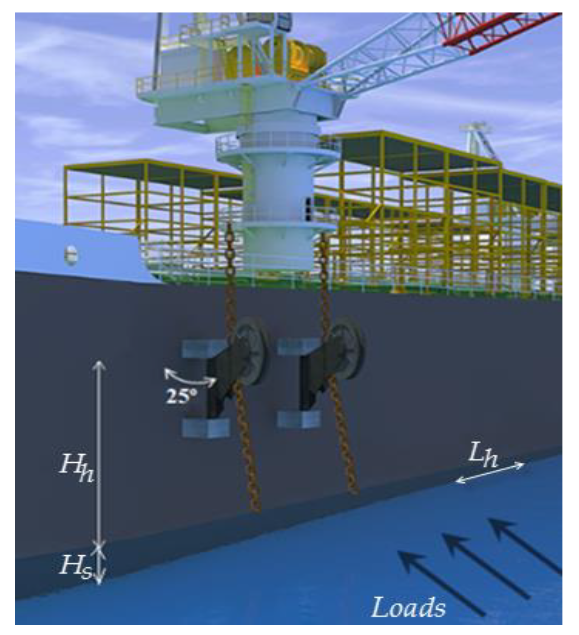
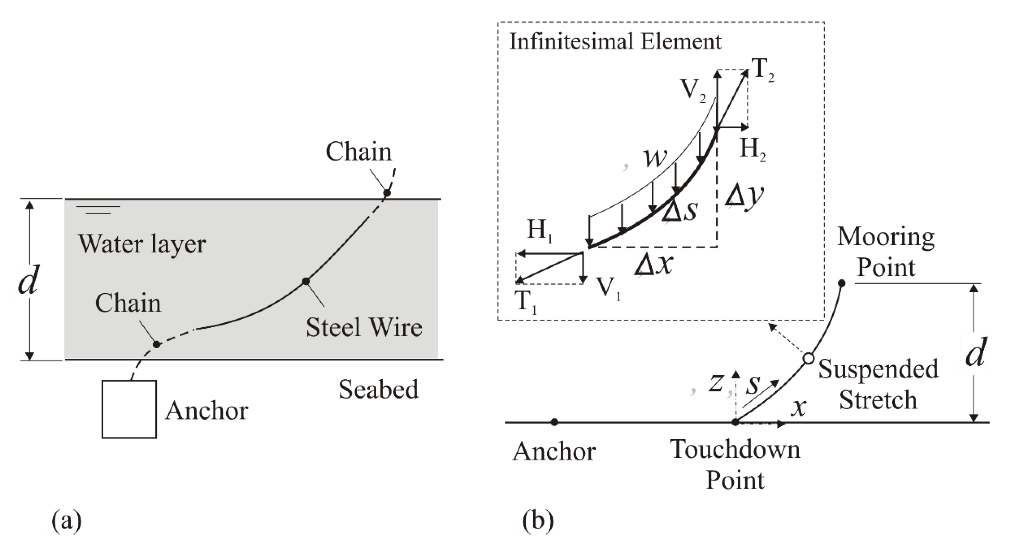
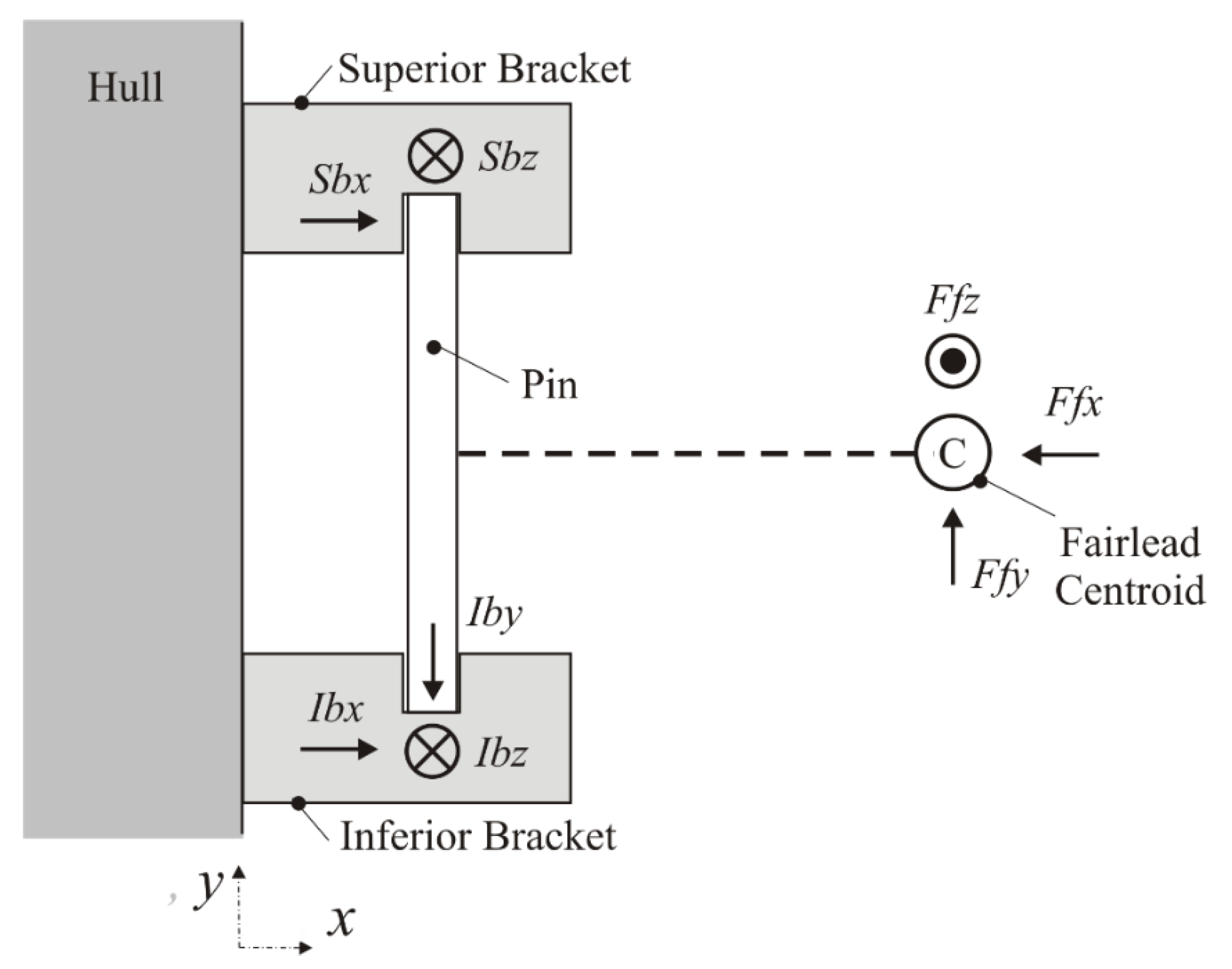
2.1. Definition of Environmental Loads and Reaction Forces

The platform considered in this study is an FPSO type, with an SM type composed of 24 lines. It is also considered that the platform is placed in the Campos Basin (Brazil), and local conditions are obtained from the Det Norsk Veritas (DNV) standards [16,17]. A platform hull with a length of Lh = 280 m and a height of Hh = 16 m is considered, based on FPSO models operating in this region of Brazil (see Figure 2). The areas exposed to the sea current, wind flow, and wave incidence are, respectively, Acurrent = H S · L h = 2240 m2; Awind = H h · L h = 4480 m2; and Awave = 2 · H S · L h = 4480 m2. The velocities of water current and wind flow on average are given, respectively, by Vcurrent = 1.6 and Vwind = 35 m/s. The densities of water and air are, respectively, ρw = 1040 [37] and ρa = 1.3 kg/m³ [16]. Moreover, an ocean depth of d = 1355 m is considered.
In this study, as a simplification hypothesis the oscillatory components of the loads generated by winds and waves are disregarded since this is the first developed model. Therefore, the analysis is restricted to observing the maximum load’s resistance through static analysis, not the useful life related to the cyclic load. This simplified approach is justified, since the thicknesses of the steel plates of the brackets were reduced by 75% from the real bracket geometry, aiming to create a more suitable scenario for the welding procedures. Despite this, the present method does not consider cyclic loadings that reduce the system’s lifespan. Moreover, loads that lead to failure by fatigue are not estimated here. Therefore, once brackets’ main failure mechanisms are due to cyclic loading, causing fatigue, it is recommended to expand the present method to comply with the cyclic loads in future studies. It is worth mentioning that the DNV standard [16] supplies the required data for calculating these loads. DNV [16] also proposes different action angles of the waves, currents, and wind loads. Despite this, only one angle is considered (perpendicular to the hull loads) to obtain a more critical situation on the analyzed devices.
The current, wind, and wave static loads can be calculated by [16,17,35]:
F c u r r e n t = 1 2 ρ w c A c u r r e n t V c u r r e n t 2 ,
F w i n d = 1 2 ρ a c A w i n d V w i n d 2 ,
F w a v e = ρ w g H s A w a v e 32 = ρ w g H S 2 L h 16 ,
where c is the drag coefficient (considered as 1.98 [38]), g is the gravity acceleration (m2/s), and HS is the significant wave height (m). It is worth mentioning that, in agreement with DNV-GL(Det Norske Veritas - Germanischer Lloyd) [17], the HS value in Campos’s basin is 8.0 m. To consider strong wave conditions, the HS value was multiplied by a coefficient equal to 2.
Kawasaki’s methodology [36] was applied to obtain the reaction to environmental loading generated in the mooring lines. When analyzing the effect of extensibility on mooring lines for a catenary-type system, it was observed that the inextensible lines break with loads 40% lower than the extensible lines, thus making the consideration of the inextensible line a more conservative approach. Figure 3 aids in understanding the characteristic equation’s determination to model the loads in the mooring line. It is essential to point out that assumptions of the flat ocean floor’s surface and the mooring line’s infinite axial stiffness must be adopted for the equation to be valid.
From Figure 3b, the balance of forces in the horizontal direction (considering the sum of horizontal loads as null) can be written as:
Σ F x = 0 = H 2 H 1 ,
where the horizontal loads H1 and H2 are given, respectively, by:
H 1 = T 1 . cos ( θ 1 ) ,
H 2 = T 2 . cos ( θ 2 ) .
In sequence, the balance of forces in the vertical direction (considering the sum of horizontal loads as null) can be written as:
Σ F y = 0 = V 2 V 1 ( w · Δ s ) ,
where w is the submerge line weight (N/m) and Δs is the infinitesimal element (m). The vertical loads V1 and V2 are given, respectively, by:
V 1 = T 1 . sin ( θ 1 ) ,
V 2 = T 2 . sin ( θ 2 ) .
After some mathematical work, it is possible to obtain the length of catenary (S) and the projected length in x and y directions, which are used to estimate the sum of horizontal loads. The equations developed so far admit that the horizontal loads H and the linear weight w are constant. Still, the mooring line’s specific weight in the submerged region is the material’s weight minus the buoyancy. Thus, for the same horizontal load, the variation in specific weight changes the catenary’s length, increasing the weight of the line. When dry, it results in a shorter catenary with a smaller mooring radius.
Then, the differential equation which models the catenary mooring line considering a limit of the catenary length Δs 0 can be defined by:
H w d η d x = 1 η 2 ,
where η = dy/dx. The Equation (10) can be used to determine the horizontal load in each mooring line.
In this study, a mooring line with a linear weight equivalent to a totally submerged chain is adopted, disregarding any radius size restrictions.
Here, the averaged fixed horizontal load (Hav) is given by:
H a v = i = 1 N H i N ,
where Hi represents the horizontal load in each line of the mooring system (N) and N is the number of mooring lines.
The DNV standard [16] mentions three limit states to be considered in the design of a mooring system: the Ultimate Limit State (ULS), Accidental Limit State (ALS), and Fatigue Limit State (FLS). The ULS represents a state where the environmental loads acting on the system are the maximum, and the integrity of all lines and equipment in the mooring system is guaranteed to maintain the platform’s positioning for the extreme expected environmental conditions. According to the DNV standard [16], the ALS covers the scenario where one or more mooring lines or equipment that supports them failed for some reason. In this situation, other lines must support the extra load for each mooring line. In the report of Finucane [5], the vessel loses its design position, and several lines can break in sequence due to the overload generated by the failure of a first mooring line, exemplifying the importance of considering this kind of situation. Finally, the FLS addresses the action of oscillatory loads on lines and equipment, analyzing their useful life for the state of fatigue. This type of analysis is extremely important due to the friction in the movement of the links and the various regions welded in the brackets and between them and the hull.
For the present study, only the first two limit states (ULS and ALS) were considered. Four lines were removed for the platform design for the accidental limit state, maintaining the same maximum environmental load. Table 1 shows the environmental loads calculated with the DNV standard used for predicting the ULS and ALS. For the ULS, the environmental load is shared between 24 mooring structures distributed along the hull. In comparison, in the ALS the distribution is performed for only 20 structures (considering the failure of 4 components).
After defining environmental loads, the mooring lines’ forces are predicted by the environmental loads and the wet line’s weight. A free body diagram in the anchorage line is done, and the reaction forces are calculated in the centroid of the fairlead. An inextensible line is taken into account to calculate reaction forces to make a more conservative evaluation. Since the fairlead is fixed to the brackets by an axis, supported only by the inferior bracket in the vertical axis, and in the horizontal axis for both brackets, calculations were made to determine the loads in each bracket. Figure 4 presents the distances adopted to define the free body diagram of the problem. There must be an inclination in the fairlead since it is not perpendicular to the hull; thus, the horizontal load acting in the fairlead centroid generates reactions in two axes in the brackets. The inclination of the fairlead in relation to the hull generally varies between 15° and 35° [4], with the angle of 25° being adopted in the present study.
Later, the reaction forces are transferred to the pin that connects the two brackets and, consequently, to the brackets. This methodology was previously presented, and some details about the free body diagram and calculation of forces can be seen in Martins et al. [39].

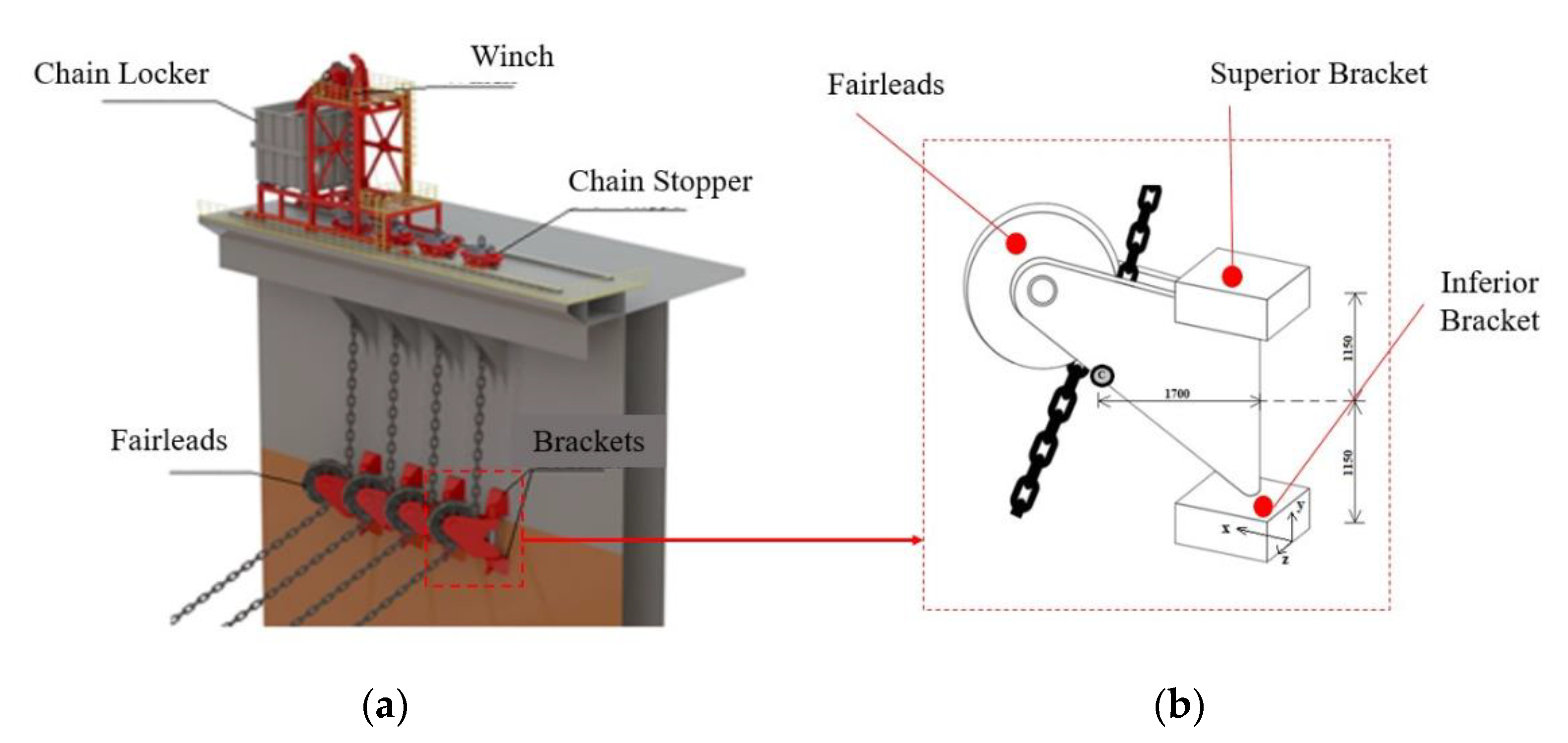
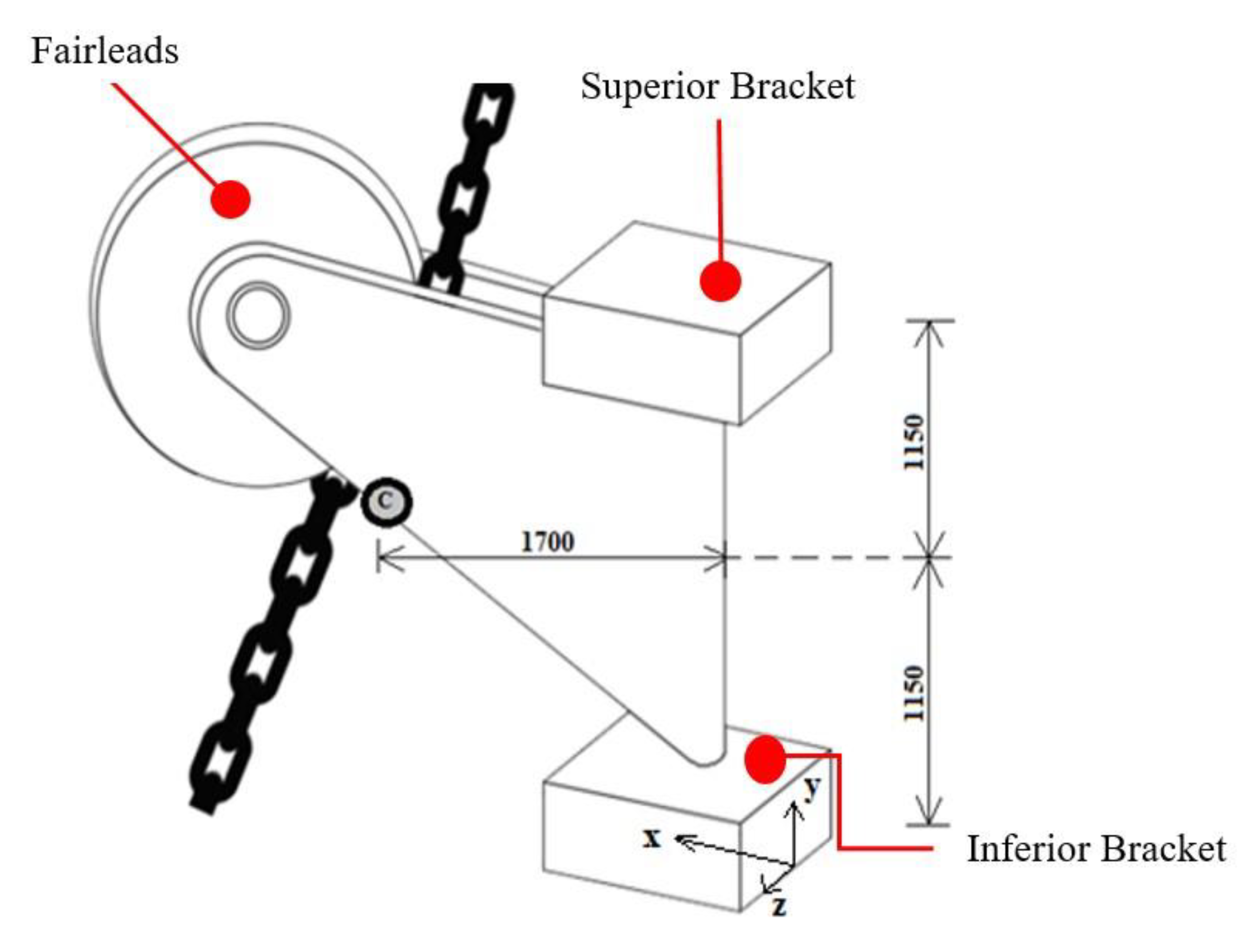
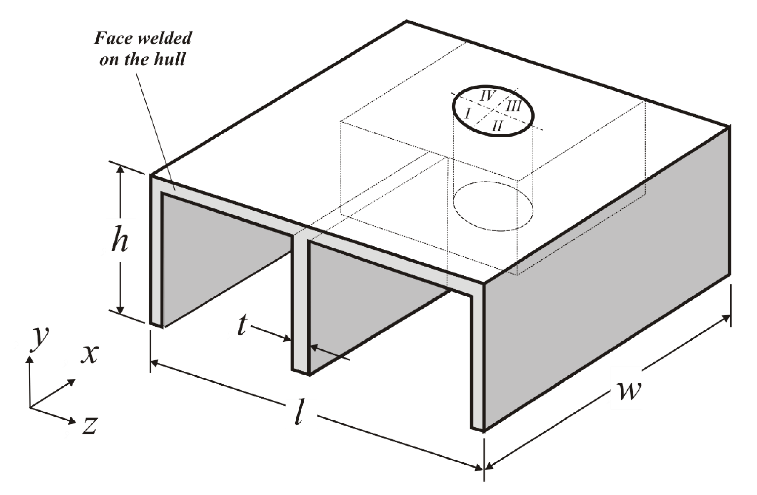
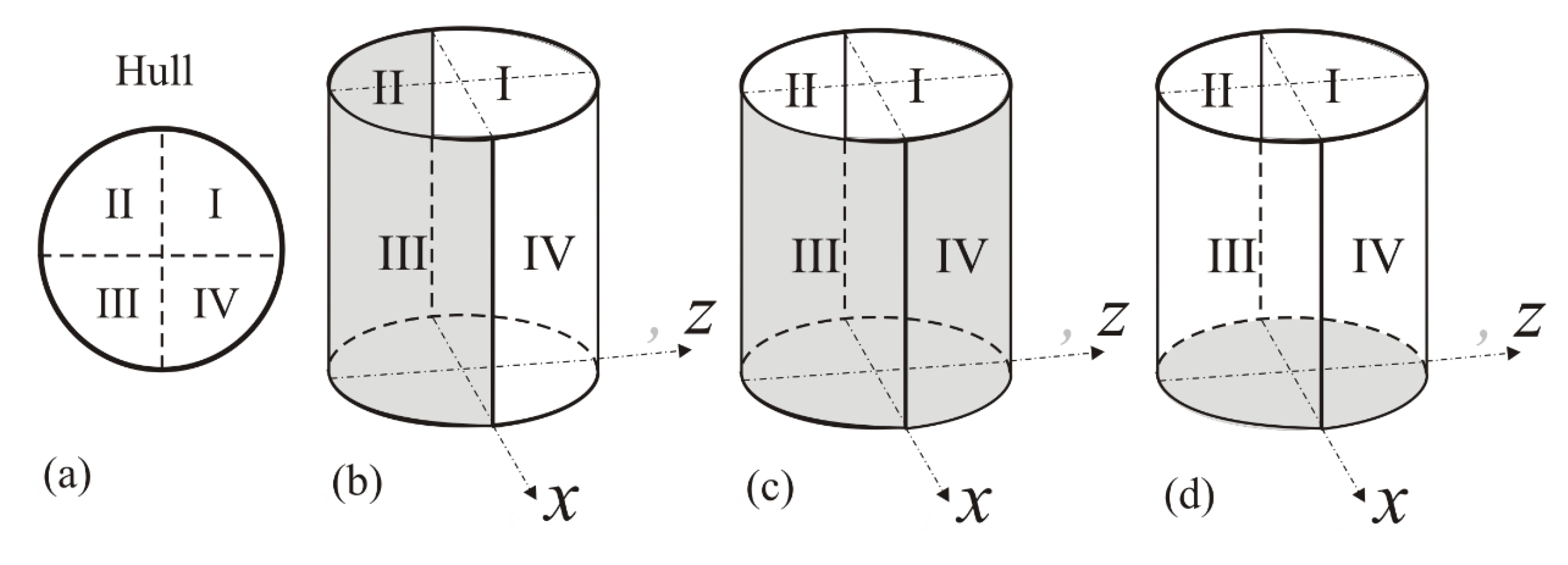
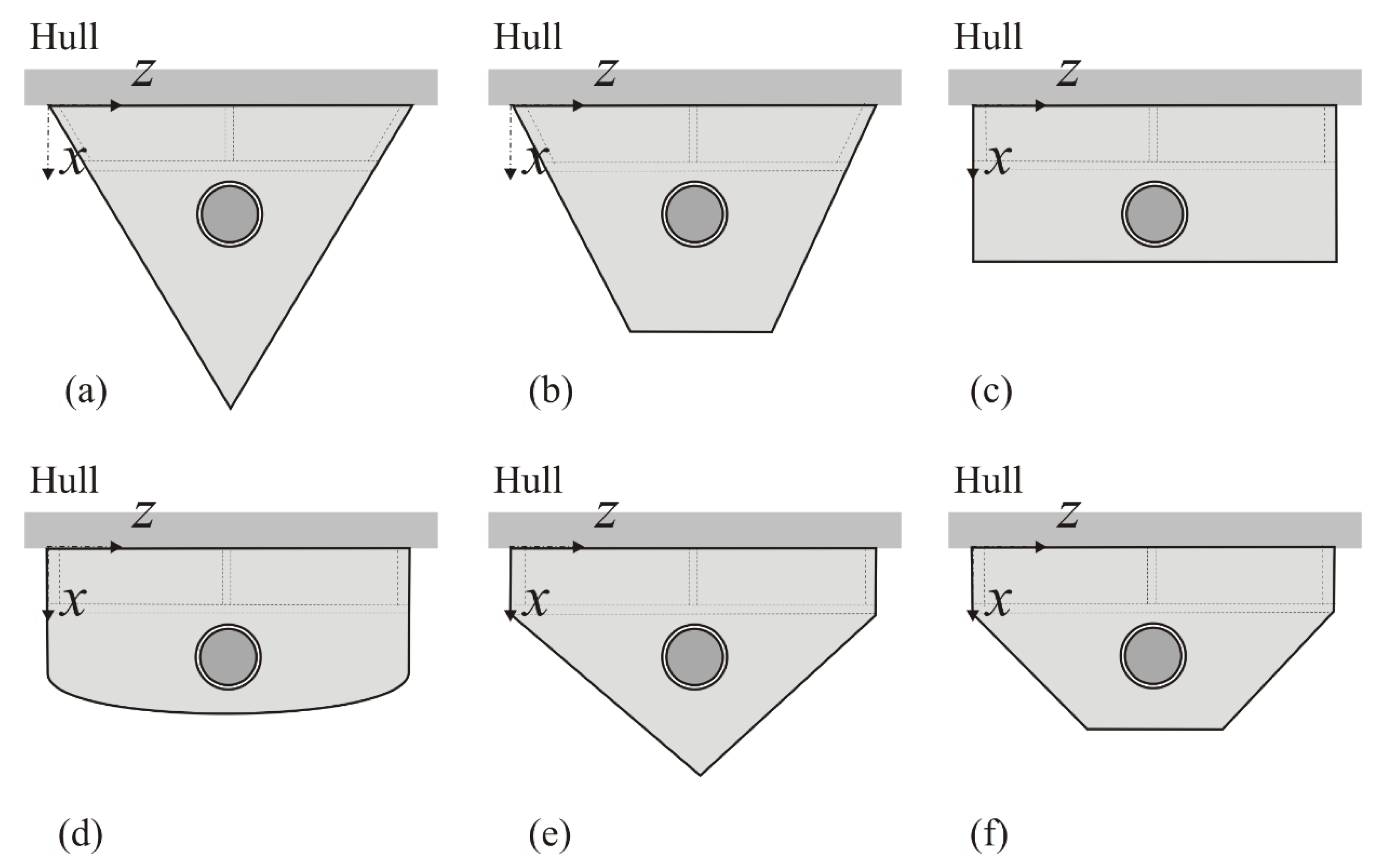
2.2. Computational Domain of Brackets and Geometrical Investigation

The next step consists of the computational solution for the forces acting on the pin that links the brackets to the fairleads. Figure 5 illustrates the computational domain of the inferior bracket, considering the rectangular base of the equipment. In the surface welded to the hull, it is imposed a fixed support condition, and the other surfaces are free to displace. It is worth mentioning that the upper bracket domain is the same used in the inferior bracket, but the brackets are mounted in a mirrored way. Therefore, the computational domain of the superior bracket is not presented here.
Figure 6 depicts a scheme of application of reaction forces in a distributed way in the brackets. Figure 6a shows a numbering of quadrants of the hole and Figure 6b–d illustrate the hole’s internal regions that receive the loads acting on the brackets in the three different axes, x, y, and z, respectively.
The brackets are composed of AH36 steel plates, with a yielding limit of 355 MPa, modulus of elasticity E = 210 GPa, and Poisson’s ratio ν = 0.30. We considered 10 mm-thick plates (four times lower than that commonly found in real applications) since the thickness of 40 mm demands a complex welding procedure during the bracket assembly. Therefore, if possible, the plate’s decrease in thickness allows an easier and faster mounting process. The hole where the pin connects the two brackets has a radius of 0.15 m. Moreover, it is 0.65 m distant from the hull and centralized in the x-direction of the plate. The height of the vertical plates of the bracket is also constant at h = 0.6 m. The bracket’s hole depth is d1 = 0.35 m, and the thickness of the perforated region of the solid in the bracket is t1 = 50 mm. The distance between the solid that encompasses the hole and the hull is d2 = 0.4 m, and the length and depth (x and z directions) are l1 = w1 = 0.35 m. The dimensions of the base plate (w and l for the rectangular plate) varied, keeping its area constant.
For the geometrical investigation, it is considered that the area of the basis plate is constant for six different geometric configurations: (1) triangular, (2) trapezoidal, (3) rectangular, (4) rectangular/elliptical, (5) rectangular/triangular, and (6) rectangular/trapezoidal. The plate basis sketch can be viewed in Figure 7a–f. All the configurations have the same area constraint, which agrees with the Constructal Design method [20,21,22,23,24,25]. The performance indicator here is the minimization of the maximum von Mises stress. In the present work, we did not explore the variation in geometric variables for each design. The purpose here is to show that the geometrical configuration can be an important subject in designing this kind of structural component used in mooring systems, a sort of proof of concept.

2.3. Numerical Procedures
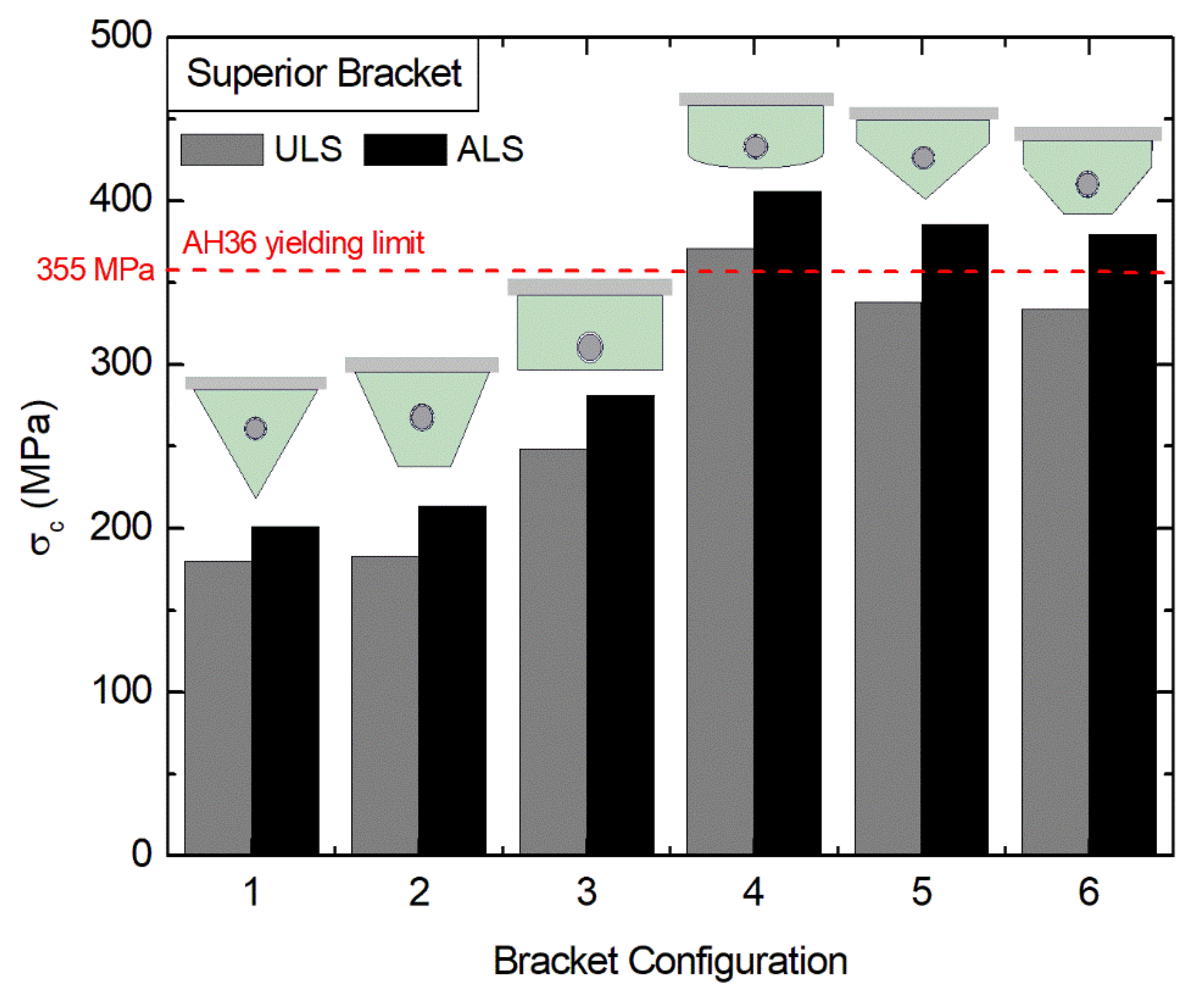
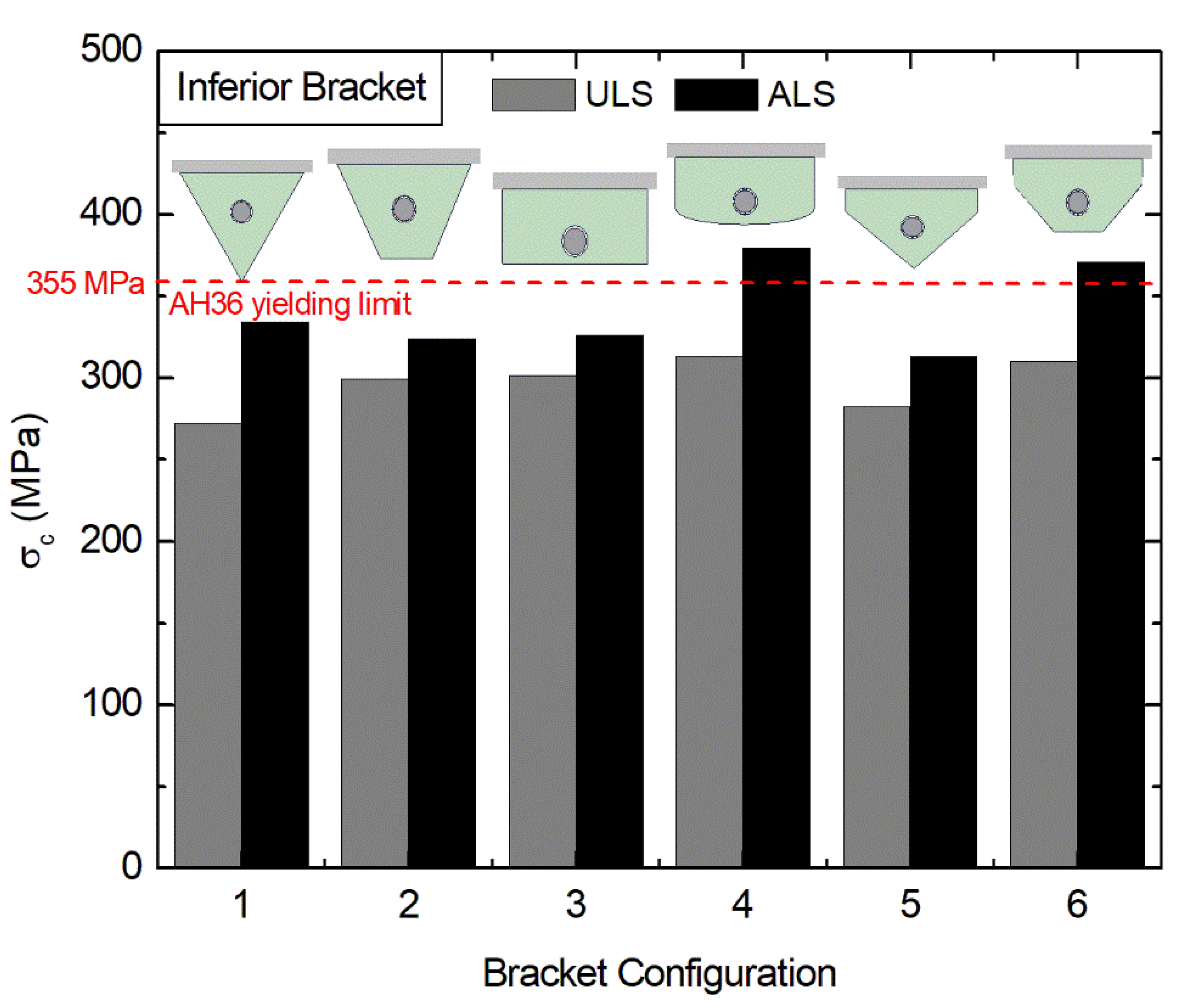
The Finite Element Method (FEM) is one of the most powerful methods to solve structural analysis [18,19]. Here, the numerical approach is made with the ANSYS Mechanical APDL [18]. The SOLID186 finite element is adopted, composed of 20 nodes with 3 degrees of freedom per node, with the translation on the x, y, and z axes [40]. The tetrahedral shape of the SOLID186 is adopted, allowing a more accurate discretization of the different proposed geometries (see Figure 7).
The influence of the number of elements over the maximum von Mises stress in the solid domain to define an adequate discretization was investigated. More precisely, the SOLID186 finite element size was varied from nearly 100,000 elements to around 500,000 elements. Table 2 shows one example of the mesh convergence test results for the case with an inferior triangular bracket (Figure 7a) under the ALS load condition.
This procedure was repeated for the twelve performed study cases (six different geometries with two different load cases). As can be seen, the results of Table 2 increase with the augmentation of the number of elements. However, the variation between a coarse and the next refined mesh showed some fluctuation, with it being difficult to establish a criterion for the definition of mesh convergence, and consequently, establish a comparison among the different geometries.
To solve this problem, one interesting strategy for the study of mesh sensitivity is the use of the Richardson extrapolation technique [41,42]. This technique proposes defining the magnitude of a dependent variable (here the maximum von Mises stress) when the number of elements tends to infinity. It consists of solving the problem with different refined meshes using the same reduction factor for three meshes. This method’s accuracy depends directly on the factor applied in the meshes’ variation and its proximity with the element size zero. For this study, simulations were performed looking for asymptotic values for meshes with different sizes of the largest element, which varied between 33 and 12.2 mm. The convergent values for maximum von Mises stress were sought without using a size variation ratio, but seeking to obtain analyses of approximately 500,000 elements.
For Richardson’s Extrapolation employed here, the same ratio (r) is adopted to variate the number of elements used in the domain. Three different meshes in the mesh convergence test interval are used; see the example in Table 2. Later, we obtained the order of convergence of the solution (p) and the estimation of the dependent variable (maximum von Mises stress) when the discretization tends to a continuum domain (σc) [41,42].
The order of solution convergence (p) and the maximum von Mises stress extrapolated for the continuum domain (σc) are, respectively, given by [41,42]:
p = ln ( σ m 1 σ m 2 σ m 2 σ m 3 ) ln ( r ) ,
σ c = σ m 3 + σ m 3 σ m 2 r p 1 ,
where r is the ratio between a coarse and a subsequent refined mesh and σm1, σm2, and σm3 are the maximum von Mises stress for the coarsest, intermediate, and most refined meshes, respectively.
Concerning the reliability of the FEM code studied here, the verifications were previously performed in the research group’s recent works. Please see the verification procedures performed in Refs. [22,39,43]. Therefore, for the sake of brevity, the computational model verification is not repeated here.

3. Results

Firstly, the loads acting in the mooring lines and some characteristics as the inclination angle between the line and the hull, line length, and anchoring radius were determined. The line’s linear weight, the depth of the water column, and the horizontal load were used to determine the line characteristics and the loads acting in the line. Table 3 presents these values for the two different states simulated with 24 lines (ULS) and 20 lines (ALS). The highest difference was found for the anchoring radius, but once radius interference with other vessels or submerged pipelines is disregarded this difference does not affect the present study. Despite this, this variable can be important in defining the anchoring placement.
After calculating the loads on the centroid of the fairlead, it is possible to consrtuct a free-body diagram in the set fairlead/bracket to estimate the reaction forces acting on the brackets. Figure 8 illustrates a lateral view of the brackets and the pin that connects them to the fairlead. Table 4 presents the reaction forces calculated in the brackets under two ULS and ALS conditions. It is possible to observe that the inferior bracket is subject to higher force magnitudes than the superior bracket, mainly because it absorbs the loads in the y-axis, which does not happen with the superior bracket. As expected, the ALS condition’s reaction forces are higher than those found for the ULS condition.
Finally, Figure 9 shows the maximum von Mises stress in the upper bracket for the six different geometric configurations considering the ULS and ALS conditions. Figure 10 presents the same investigation for the inferior bracket. The results indicated that the triangular geometry of the ULS condition leads to the best mechanical performance for both brackets (superior and inferior). For the ALS condition, the best shape for the inferior bracket changes to the trapezoidal configuration, indicating that different designs can be recommended for different brackets or conditions. For the superior bracket, the triangular shape leads to a maximum von Mises stress of σc = 179.82 MPa in the ULS condition. This performance is 2.1 times better than the σc found for the rectangular/elliptical configuration (which surpassed the material yielding stress limit). The latter configuration is the worst among the compared geometries. The trapezoidal and rectangular configurations also have a good performance for the superior bracket, quite inferior to the triangular one.
In contrast, the rectangular/triangular and rectangular/trapezoidal configurations have a poor performance, with the magnitudes of von Mises stresses almost achieving the yielding limit stress of the material. It is possible to notice that the performance is more homogeneous among the different configurations for the inferior bracket. Moreover, the magnitudes were higher those that reached for the superior bracket, with the best performance for ULS and ALS conditions being reached, respectively, for the triangular (with σc = 272.07 MPa) and the rectangular/triangular (with σc = 313.01 MPa) configurations. In general, the results demonstrated that the geometric design could be an essential aspect to improve the stress distribution in the bracket domain.
Finally, regarding the superior brackets and the ULS conditions (see Figure 9) the von Mises stress distributions for the best (triangular) and worst (rectangular/elliptical) bracket shapes are depicted, respectively, in Figure 11 and Figure 12.
One can note in Figure 11 and Figure 12 that the maximum von Mises stress is achieved for a specific point located at the region where the central vertical plate is fixed to the central bracket block. It is worth mentioning that, in a general way, this behavior was also observed for the other proposed bracket geometries.

4. Conclusions

The present study developed a computational methodology for predicting the mechanical behavior of brackets found in mooring systems, a topic that has been scarcely investigated in the literature. The computational methodology was divided into several steps, encompassing the environmental loads that the structures are subjected to until using an FEM code to predict the von Mises stress distribution. Two different conditions of load states are investigated (ULS and ALS). The developed methodology was applied to obtain theoretical recommendations about the brackets’ design based on the Constructal Design method.
The obtained results indicated that the developed methodology could be promising for the brackets’ analysis and design. Even considering brackets composed of plates four times thinner than those found in real applications, under ULS conditions the best configurations reached maximum von Mises stress magnitudes almost two times inferior to the material yielding limit. The results also proved that the geometrical configuration could be an essential aspect of the investigation to improve the brackets’ mechanical performance. In the comparison between the best and worst shapes, ratios of performance of 2.1 times were noticed. For the present study, the results recommended triangular shapes for the ULS conditions in both brackets. For the ALS condition, the rectangular/triangular shape was the best for the inferior bracket. The triangular shape was the best for the superior one, indicating that different designs can be recommended for superior and inferior brackets since they are subjected to different loads.
A more detailed analysis of the geometrical configurations studied here (mainly varying the basis plate dimensions) is recommended for future studies. Moreover, the implementation of dynamic loads in the analysis would be an important investigation with which to better predict more realistic conditions. Another critical aspect is investigating the problem under survival conditions, a limit situation for design in the mooring system.

Author Contributions

Conceptualization, K.L.M., L.A.I., and E.D.d.S.; methodology, K.L.M., V.T.P., L.A.I., and E.D.d.S.; software, K.L.M., L.A.I., and M.V.R.; validation, K.L.M., V.T.P., M.V.R., and L.A.I.; formal analysis, L.A.O.R., C.F., M.V.R., L.A.I., and E.D.d.S.; investigation, K.L.M., V.T.P., C.F., and L.A.I.; resources, L.A.I., L.A.O.R., E.D.d.S., and C.F.; data curation, K.L.M., V.T.P., L.A.I., and E.D.d.S.; writing—original draft preparation, K.L.M. and E.D.D.S.; writing—review and editing, C.F., M.V.R., L.A.O.R., and L.A.I.; visualization, C.F., M.V.R., and L.A.O.R.; supervision, L.A.I., and E.D.d.S.; project administration, L.A.I. and E.D.d.S.; funding acquisition, C.F. and E.D.d.S. All authors have read and agreed to the published version of the manuscript.

Funding

This research was funded by the Brazilian Coordination for the Improvement of Higher Education Personnel (CAPES) (Finance Code 001); the Brazilian National Council for Scientific and Technological Development (CNPq) (Processes: 304211/2018-4, 307791/2019-0; 306012/2017-0, 306024/2017-9); and the Italian Minister of Foreign Affairs and International Cooperation (MAECI), as part of the “Two Seats for a Solar Car” international project.

Acknowledgments

K. L. Martins thank CAPES for the Master Dissertation Scholarship (Finance Code 001). C. Fragassa thanks the MAECI as part of the “Two Seats for a Solar Car” international project. MV Real, L.A.O. Rocha, L.A. Isoldi, and ED dos Santos thank CNPq for the research grant (Processes: 304211/2018-4, 307791/2019-0; 306012/2017-0, 306024/2017-9).

Conflicts of Interest

The authors declare no conflict of interest.

References

  1. Gordon, R.B.; Brown, M.G.; Allen, E.M. Mooring Integrity Management: A State-of-the-Art Review. In Proceedings of the Offshore Technology Conference, Houston, TX, USA, 5–8 May 2014; OCT 25134. pp. 1–12. [Google Scholar]
  2. Pecher, A.; Foglia, A.; Kofoed, J.P. Comparison and sensitivity investigations of a CALM and SALM type mooring system for wave energy converters. J. Mar. Sci. Eng. 2014, 2, 93–122. [Google Scholar]
  3. Kasper, F.; Barros, M.; Rossi, R.; Masetti, I.; Falkenberg, E.; Karlsen, S.; Waclawek, I. DICAS—A new mooring concept for FPSO’s. In Proceedings of the Offshore Technology Conference, Houston, TX, USA, 5–8 May 1997; OTC-8439-MS. pp. 1–12. [Google Scholar]
  4. Babicz, J. Wärtsilä Encyclopedia of Marine Technology, 2nd ed.; Wärtsilä Corporation: Helsinki, Finland, 2015; pp. 1–663. [Google Scholar]
  5. Finucane, M. Details of Gryphon Incident of 4th February 2011 and Lessons Learned; Technical Report, Maersk Oil; IOSH Institution of Occupational Safety and Health: Aberdeen, UK, 2012. [Google Scholar]
  6. Qiao, D.; Yan, J.; Ou, J. Fatigue analysis of deepwater hybrid mooring line under corrosion effect. Pol. Marit. Res. 2014, 21, 68–76. [Google Scholar]
  7. Azcona, J.; Munduate, X.; Gonzáles, L.; Nygaard, T.A. Experimental validation of a dynamic mooring lines code with tension and motion measurements of a submerged chain. Ocean Eng. 2017, 129, 415–427. [Google Scholar]
  8. Shen, K.; Guo, Z.; Wang, L. Prediction of the whole mooring chain reaction to cyclic motion of a fairlead. Bull. Eng. Geol. Environ. 2019, 78, 2197–2213. [Google Scholar]
  9. Kim, M.H.; Koo, B.J.; Mercier, R.M.; Ward, E.G. Vessel/mooring/riser coupled dynamic analysis of a turret-moored FPSO compared with OTRC experiment. Ocean Eng. 2005, 32, 1780–1802. [Google Scholar]
  10. Hollyhead, C.J.; Townsend, N.C.; Blake, J.I.R. Experimental investigations into the current-induced motion of a lifeboat at a single point mooring. Ocean Eng. 2017, 146, 192–201. [Google Scholar]
  11. Wang, S.; Wang, X.; Woo, W.L.; Seow, T.H. Study on green water prediction for FPSOs by a practical numerical approach. Ocean Eng. 2017, 143, 88–96. [Google Scholar]
  12. Pradana, M.R.; Qian, X.; Ahmed, A. Efficient discrete element simulation of man-aged ice actions on moored floating platforms. Ocean Eng. 2019, 190, 106483. [Google Scholar]
  13. Touzon, I.; Nava, V.; Gao, Z.; Mendikoa, I.; Petuya, V. Small scale experimental validation of a numerical model of the HarshLab2.0 floating platform coupled with a non-linear lumped mass catenary mooring system. Ocean Eng. 2020, 200, 107036. [Google Scholar]
  14. Jin, C.; Bakti, F.P.; Kim, M. Multi-floater-mooring coupled time-domain hydro-elastic analysis in regular and irregular waves. Appl. Ocean Res. 2020, 101, 102276. [Google Scholar]
  15. Skjetne, R.; Zhengru, R. A survey on modeling and control of thruster-assisted position mooring systems. Mar. Struct. 2020, 74, 102830. [Google Scholar] [CrossRef]
  16. Det Norske Veritas (DNV). Offshore Standard DNV-OS-E301: Position Mooring; Det Norske Veritas (DNV): Namibia (NA), 2015. [Google Scholar]
  17. Det Norske Veritas (DNV) - Germanischer Lloyd (GL). Offshore Standard DNVGL-OS-E301: Position Mooring; Det Norske Veritas (DNV) - Germanischer Lloyd (GL): Namibia (NA), 2015. [Google Scholar]
  18. ANSYS, Inc. ANSYS Mechanical APDL Theory Reference; Release 15.0; SAS IP, Inc.: Canonsburg, PA, USA, 2013. [Google Scholar]
  19. Zienkiewicz, O.C.; Taylor, R.L.; Zhu, J.Z. The Finite Element Method: Its Basis and Fundamentals, 6th ed.; Elsevier: Oxford, UK, 2005; pp. 1–752. [Google Scholar]
  20. Bejan, A.; Lorente, S. Design with Constructal Theory; Wiley: Hoboken, NJ, USA, 2008; pp. 1–529. [Google Scholar]
  21. Bejan, A. Freedom and Evolution: Hierarchy in Nature, Society and Science; Springer: Cham, Switzerland, 2020; pp. 1–151. [Google Scholar]
  22. De Queiroz, J.; Cunha, M.L.; Pavlovic, A.; Rocha, L.A.O.; Dos Santos, E.D.; Troina, G.; Isoldi, L.A. Geometric evaluation of stiffened steel plates subjected to transverse loading for naval and offshore applications. J. Mar. Sci. Eng. 2019, 7, 7. [Google Scholar] [CrossRef] [Green Version]
  23. Magalhães, G.M.C.; Fragassa, C.; Lemos, R.L.; Isoldi, L.A.; Amico, S.C.; Rocha, L.A.O.; Souza, J.A.; Dos Santos, E.D. Numerical Analysis of the Influence of Empty Channels Design on Performance of Resin Flow in a Porous Plate. Appl. Sci. 2020, 10, 4054. [Google Scholar] [CrossRef]
  24. Vieira, R.S.; Petry, A.P.; Rocha, L.A.O.; Isoldi, L.A.; Dos Santos, E.D. Numerical evaluation of a solar chimney geometry for different ground temperatures by means of constructal design. Renew. Energy 2017, 109, 222–234. [Google Scholar] [CrossRef]
  25. Rodrigues, P.M.; Biserni, C.; De Escobar, C.C.; Rocha, L.A.O.; Isoldi, L.A.; Dos Santos, E.D. Geometric optimization of a lid-driven cavity with two rectangular intrusions under mixed convection heat transfer: A numerical investigation motivated by constructal design. Int. Commun. Heat Mass Transf. 2020, 117, 104759. [Google Scholar] [CrossRef]
  26. Gonzales, G.V.; Estrada, E.d.S.D.; Emmendorfer, L.R.; Isoldi, L.A.; Xie, G.; Rocha, L.A.O.; Dos Santos, E.D. A comparison of simulated annealing schedules for constructal design of complex cavities intruded into conductive walls with internal heat generation. Energy 2015, 93, 372–382. [Google Scholar] [CrossRef]
  27. Rocha, L.A.O.; Real, M.V.; Correia, A.L.G.; Vaz, J.; Dos Santos, E.D.; Isoldi, L.A. Geometric optimization based on the Constructal Design of perforated thin plates subject to buckling. Comput. Therm. Sci. 2012, 4, 119–129. [Google Scholar] [CrossRef] [Green Version]
  28. Lorenzini, G.; Helbig, D.; Real, M.V.; dos Santos, E.D.; Rocha, L.A.O.; Isoldi, L.A. Computational modeling and Constructal Design method applied to the mechanical behavior improvement of thin perforated steel plates subject to buckling. J. Eng. Thermophys. 2016, 25, 197–215. [Google Scholar] [CrossRef]
  29. Da Silva, C.C.C.; Helbig, D.; Cunha, M.L.; Dos Santos, E.D.; Rocha, L.A.O.; Real, M.V.; Isoldi, L.A. Numerical buckling analysis of thin steel plates with centered hexagonal perforation through constructal design method. J. Braz. Soc. Mech. Sci. Eng. 2019, 41, 309-1–309-18. [Google Scholar] [CrossRef]
  30. Pinto, V.T.; Cunha, M.L.; Troina, G.S.; Martins, K.L.; Dos Santos, E.D.; Isoldi, L.A.; Rocha, L.A.O. Constructal design applied to geometrical evaluation of rectangular plates with inclined stiffeners subjected to uniform transverse load. Res. Eng. Struct. Mat. 2019, 5, 379–392. [Google Scholar]
  31. Troina, G.S.; Cunha, M.L.; Pinto, V.T.; Rocha, L.A.O.; Dos Santos, E.D.; Fragassa, C.; Isoldi, L.A. Computational Modeling and Design Constructal Theory Applied to the Geometric Optimization of Thin Steel Plates with Stiffeners Subjected to Uniform Transverse Load. Metals 2020, 10, 220. [Google Scholar] [CrossRef] [Green Version]
  32. Amaral, R.R.; Troina, G.S.; Fragassa, C.; Pavlovic, A.; Cunha, M.L.; Rocha, L.A.O.; dos Santos, E.D.; Isoldi, L.A. Constructal design method dealing with stiffened plates and symmetry boundaries. Theor. Appl. Mech. Let. 2020, 10, 266–372. [Google Scholar]
  33. Mardanpour, P.; Izadpanahi, E.; Rastkar, S.; Lorente, S.; Bejan, A. Constructal design of aircraft: Flow of stresses and aeroelastic stability. AIAA J. 2019. [Google Scholar] [CrossRef]
  34. Izadpanahi, E.; Moshtaghzadeh, M.; Radnezhad, H.R.; Mardanpour, P. Constructal approach to design of wing cross-section for better flow of stresses. AIAA J. 2020, in press. [Google Scholar] [CrossRef]
  35. Bergdahl, L.; Kofoed, J.P. Simplified Design Procedures for Moorings of Wave-Energy Converters: Deliverable 2.2; DCE Technical Report nº172; Department of Civil Engineering, Aalborg University: Aalborg, Denmark, 2015. [Google Scholar]
  36. Kawasaki, P.Y. Analysis of Anchoring Lines of Ocean Platforms Considering Several Sections and Partially Buried Line (In Portuguese). Ph.D. Thesis, Federal University of Rio de Janeiro, Rio de Janeiro, Brazil, 2010. (In Portuguese). [Google Scholar]
  37. Rocha, L.; Azevedo, C. Projetos de Poços de Petróleo—Geopressões e Assentamento de Colunas de Revestimento; Interciência: Rio de Janeiro, Brazil, 2019; pp. 1–696. (In Portuguese) [Google Scholar]
  38. Hoerner, S.F. Fluid Dynamic Drag: Practical Information on Aerodynamic Drag and Hydrodynamic Resistance; Hoerner Fluid Dynamics: Bakersfield, CA, USA, 1965; pp. 1–455. [Google Scholar]
  39. Martins, K.L.; Pinto, V.T.; Rocha, L.A.O.; Dos Santos, E.D.; Isoldi, L.A. Numerical evaluation of the mechanical behavior of an FPSO mooring system fairleads foundations due to maximum environmental loads. Res. Eng. Struct. Mat. 2019, 5, 355–366. [Google Scholar] [CrossRef]
  40. Marinkovic, D.; Rama, G.; Zehn, M. Abaqus implementation of a corotational piezoelectric 3-node shell element with drilling degree of freedom. FU Mech. Eng. 2019, 17, 269–283. [Google Scholar] [CrossRef] [Green Version]
  41. Roache, P.J. Verification and Validation in Computational Science and Engineering; Hermosa Publishers: Albuquerque, NM, USA, 1998; pp. 1–446. [Google Scholar]
  42. The American Society of Mechanical Engineers (ASME). An Illustration of the Concepts of Verification and Validation in Computational Solid Mechanics, V&V 10.1-2012 Standard; The American Society of Mechanical Engineers: New York, NY, USA, 2012. [Google Scholar]
  43. Lima, J.P.S.; Cunha, M.L.; Dos Santos, E.D.; Rocha, L.A.O.; Real, M.V.; Isoldi, L.A. Constructal design for the ultimate buckling stress improvement of stiffened plates submitted to uniaxial compressive load. Eng. Struct. 2020, 203, 109883. [Google Scholar] [CrossRef]
Figure 1. Illustration of a mooring system of an oil production platform vessel: (a) the full view of the mooring system mounted in the platform hull, (b) local view of the set fairlead-brackets component.
Jmse 08 00929 g001
Figure 2. Dimensions of the hull based on Floating, Production, Storage, and Offloading (FPSO) models operating in Campos’s basin.
Jmse 08 00929 g002
Figure 3. Illustration of the line segments adopted in the present problem and the forces acting in the catenary mooring line’s infinitesimal element: (a) global view, (b) forces acting in the infinitesimal element of the line.
Jmse 08 00929 g003
Figure 4. Sketch of the fairlead/bracket set with the position of the centroid of the fairlead (values in mm).
Jmse 08 00929 g004
Figure 5. Computational domain of the inferior bracket for the case with a rectangular base plate.
Jmse 08 00929 g005
Figure 6. Scheme of application of the reaction forces applied in the hole of the bracket: (a) hole area division in quadrants for application of forces, (b) areas where loads on z-axis are applied, (c) areas where loads on the x-axis are applied, (d) areas where loads on the y-axis are applied.
Jmse 08 00929 g006
Figure 7. Representation of the different configurations of brackets studied here: (a) triangular, (b) trapezoidal, (c) rectangular, (d) rectangular/elliptical, (e) rectangular/triangular, (f) rectangular/trapezoidal.
Jmse 08 00929 g007
Figure 8. Free-body diagram scheme in the set fairlead/bracket and the reaction forces in the problem.
Jmse 08 00929 g008
Figure 9. Maximum von Mises stress obtained in the superior bracket for the six different geometric configurations under the ULS and ALS conditions.
Jmse 08 00929 g009
Figure 10. Maximum von Mises stress obtained in the inferior bracket for the six different geometric configurations under the ULS and ALS conditions.
Jmse 08 00929 g010
Figure 11. Distribution of the von Mises stress (in MPa) for the triangular shape of the superior bracket under ULS conditions: (a) superior view and (b) inferior view.
Jmse 08 00929 g011
Figure 12. Distribution of the von Mises stress (in MPa) for the rectangular/elliptical shape of the superior bracket under ULS conditions: (a) superior view and (b) inferior view.
Jmse 08 00929 g012
Table 1. Environmental loads calculated for an FPSO (magnitudes in MN).
Environmental Load TypeTotal LoadPer Line (24 Lines)Per Line (20 Lines)
Wind6.690.280.33
Current5.960.250.30
Waves11.430.480.57
Total24.081.011.20
Table 2. Grid independence study for the inferior triangular bracket subjected to the ALS condition of loading.
Number of ElementsLargest Element Size (mm)Maximum von Mises Stress (MPa)
110,38530.0275.83
144,32127.0270.58
188,80524.0273.93
222,37922.0288.52
298,35121.0289.77
376,49019.0292.57
449,26518.0305.54
463,52817.5298.33
510,01117.0297.50
563,92516.5303.30
Table 3. Characteristics of the mooring lines and loads of the line applied in the fairlead centroid.
Characteristic/Loads24 Lines (ULS)20 Lines (ALS)
Line length (m)1554.521584.22
Anchoring radius (m)761.91820.81
Angle between the line and hull (°)60.6058.80
Fairlead centroid load (x axis) (kN)421.38505.66
Fairlead centroid load (y axis) (kN)1780.551987.95
Fairlead centroid load (z axis) (kN)902.961083.55
Table 4. Reaction forces calculated in the superior and inferior brackets.
Reaction ForcesULS (kN)ALS (kN)
Sbx−1105.37−1258.66
Sbz785.18942.22
Ibx1526.751680.05
Iby1780.551987.95
Ibz785.18942.22
Publisher’s Note: MDPI stays neutral with regard to jurisdictional claims in published maps and institutional affiliations.

