Seismic Dynamics of Pipeline Buried in Dense Seabed Foundation


Abstract
:1. Introduction
2. Coupled Numerical Model: FSSI-CAS 2D
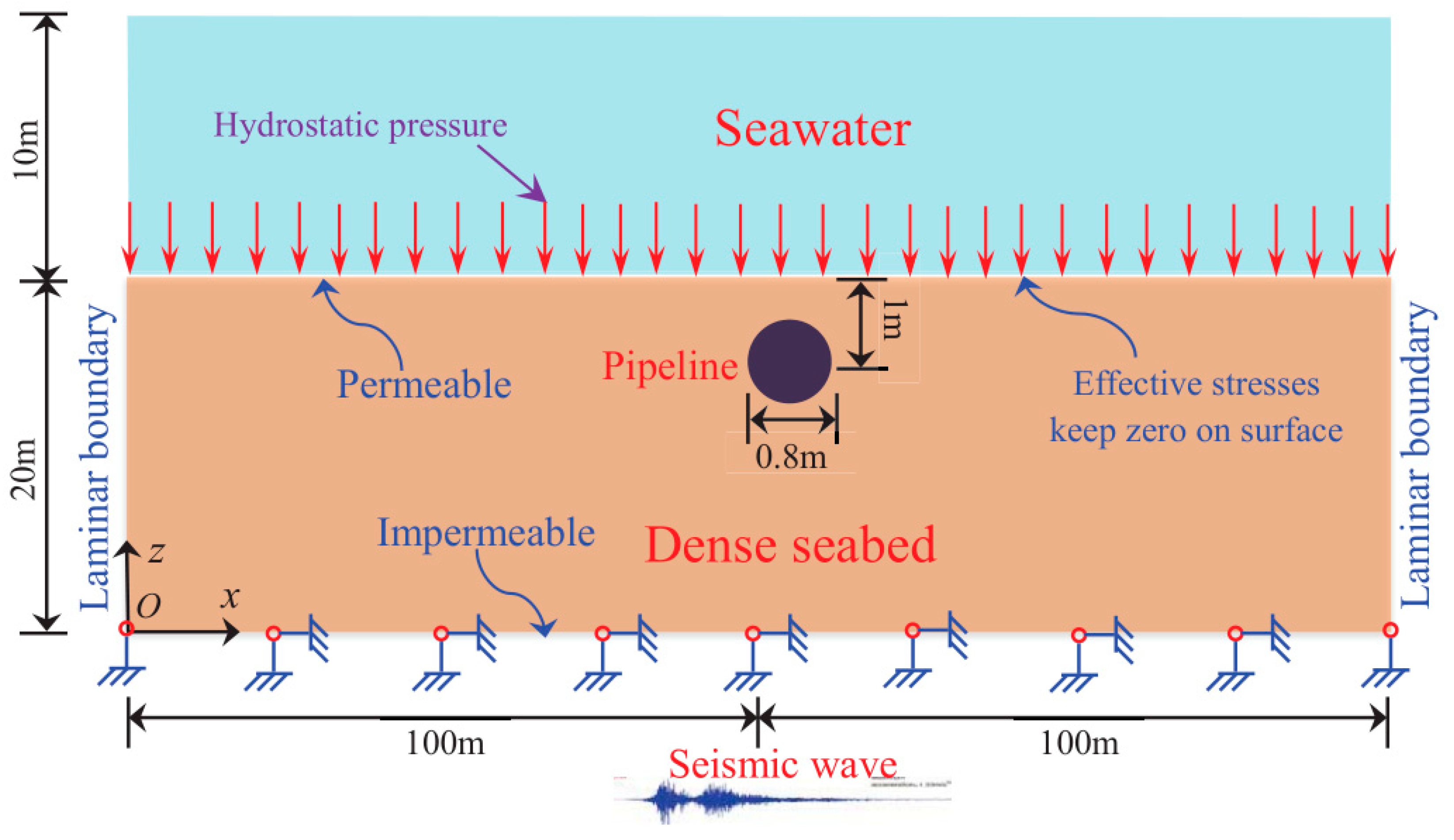
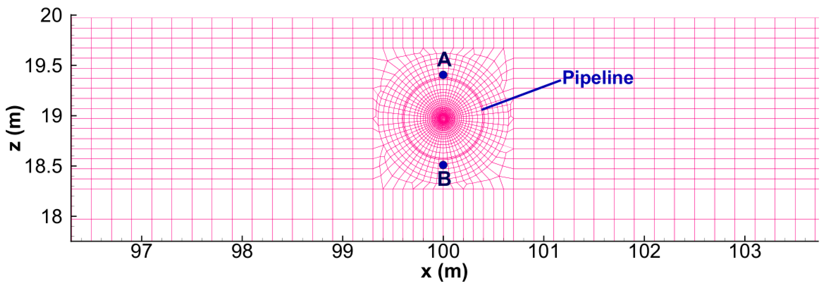
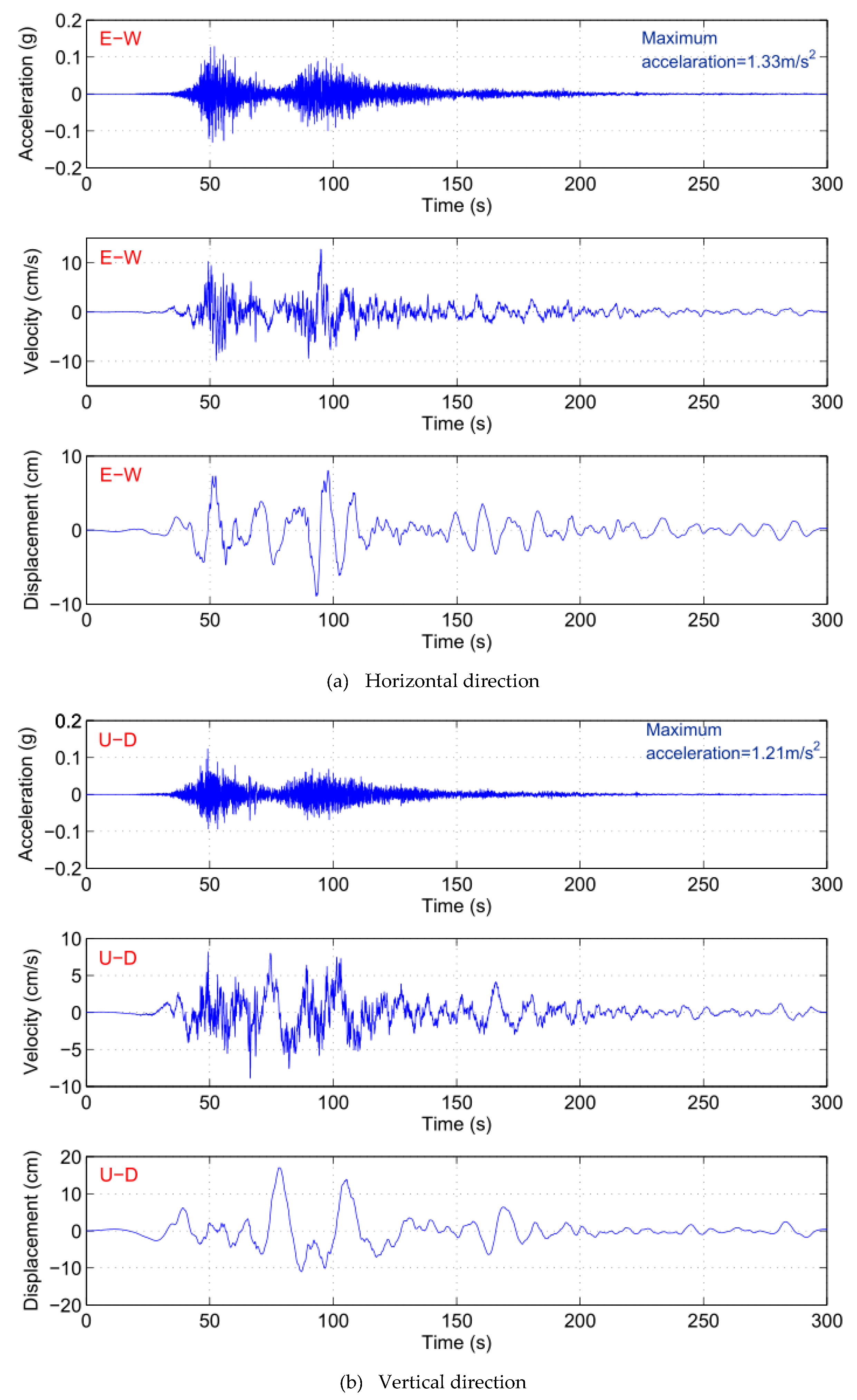
3. Computational Domain, Boundary Condition, Seismic Wave and Parameters
4. Results
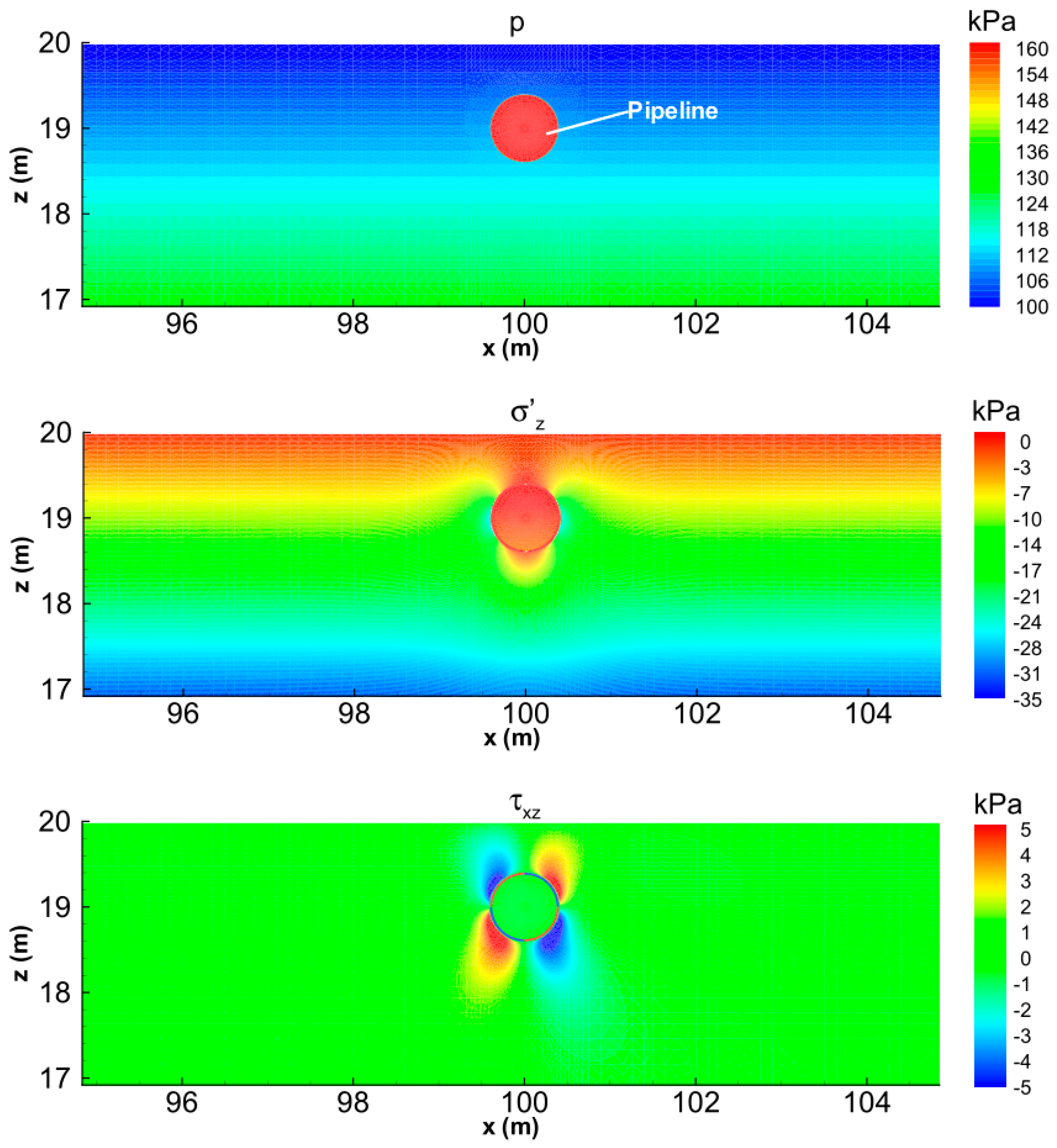
4.1. Initial Status
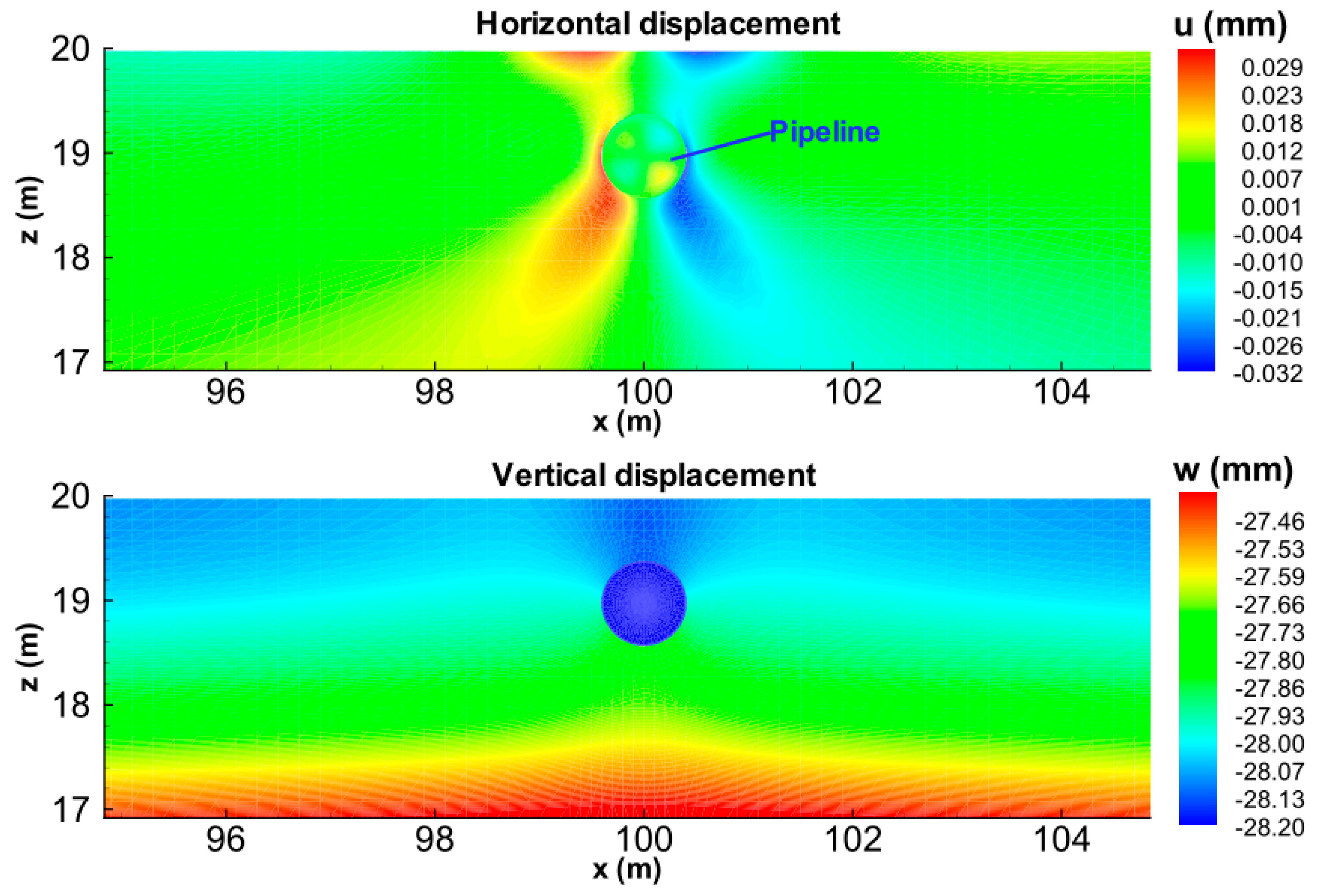
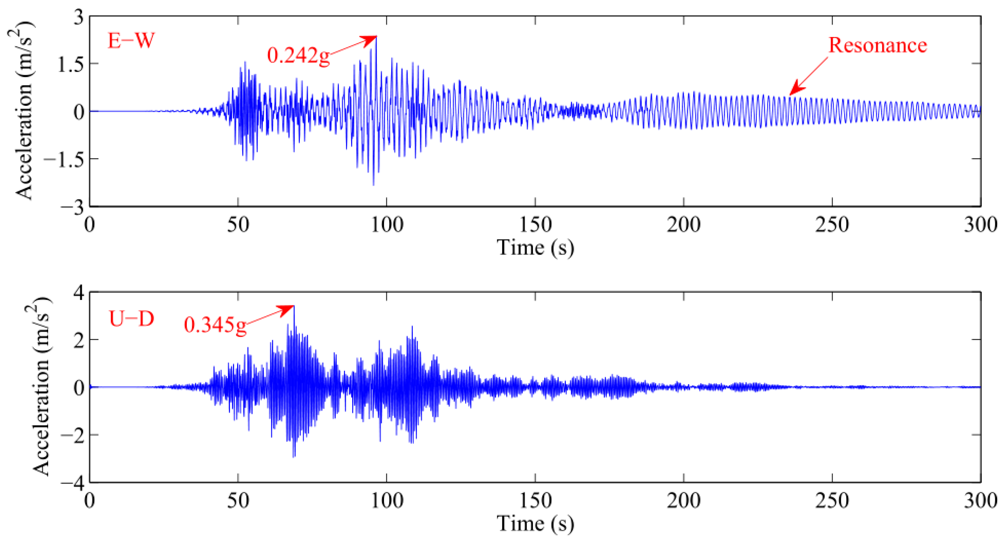
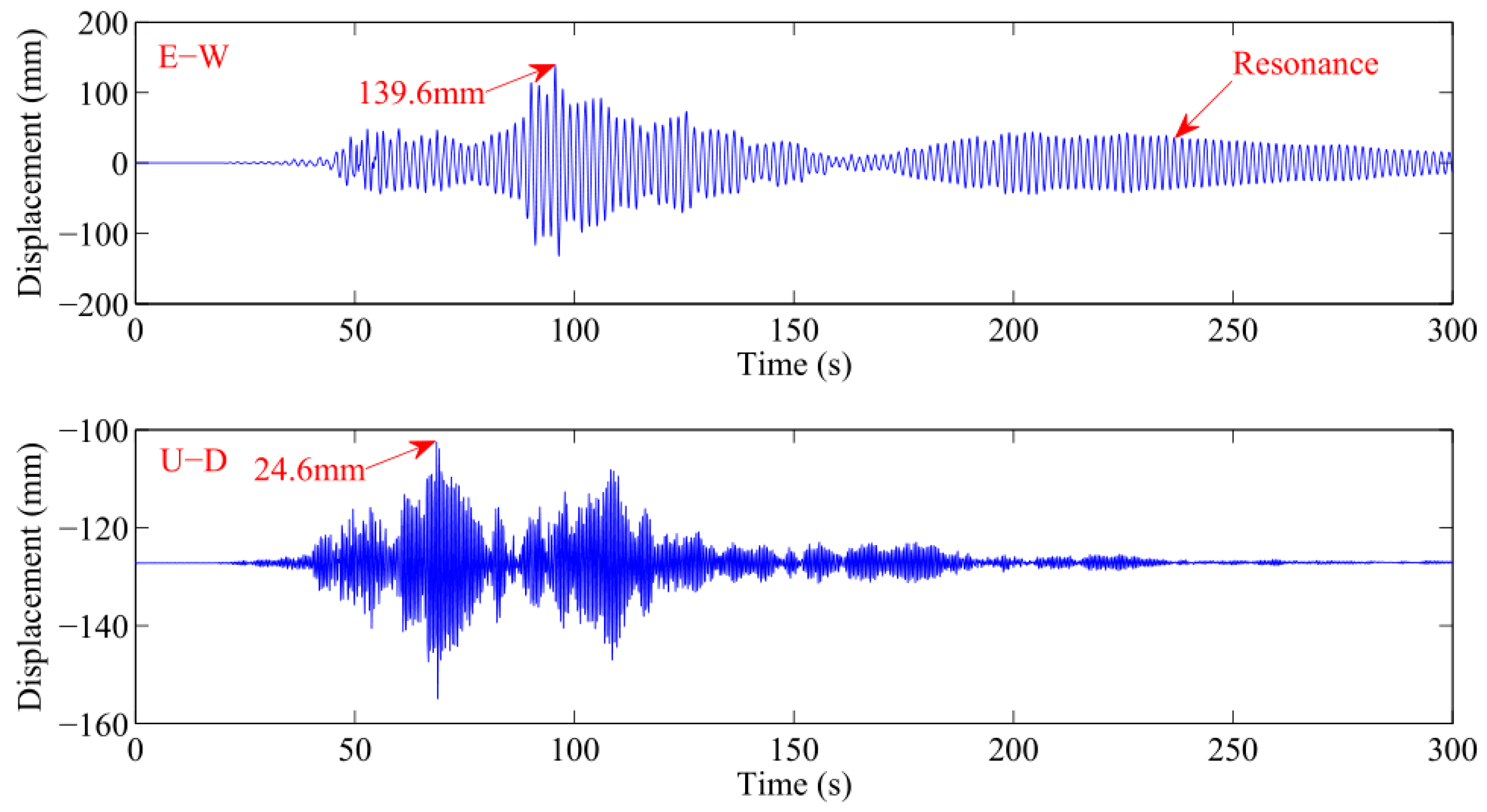
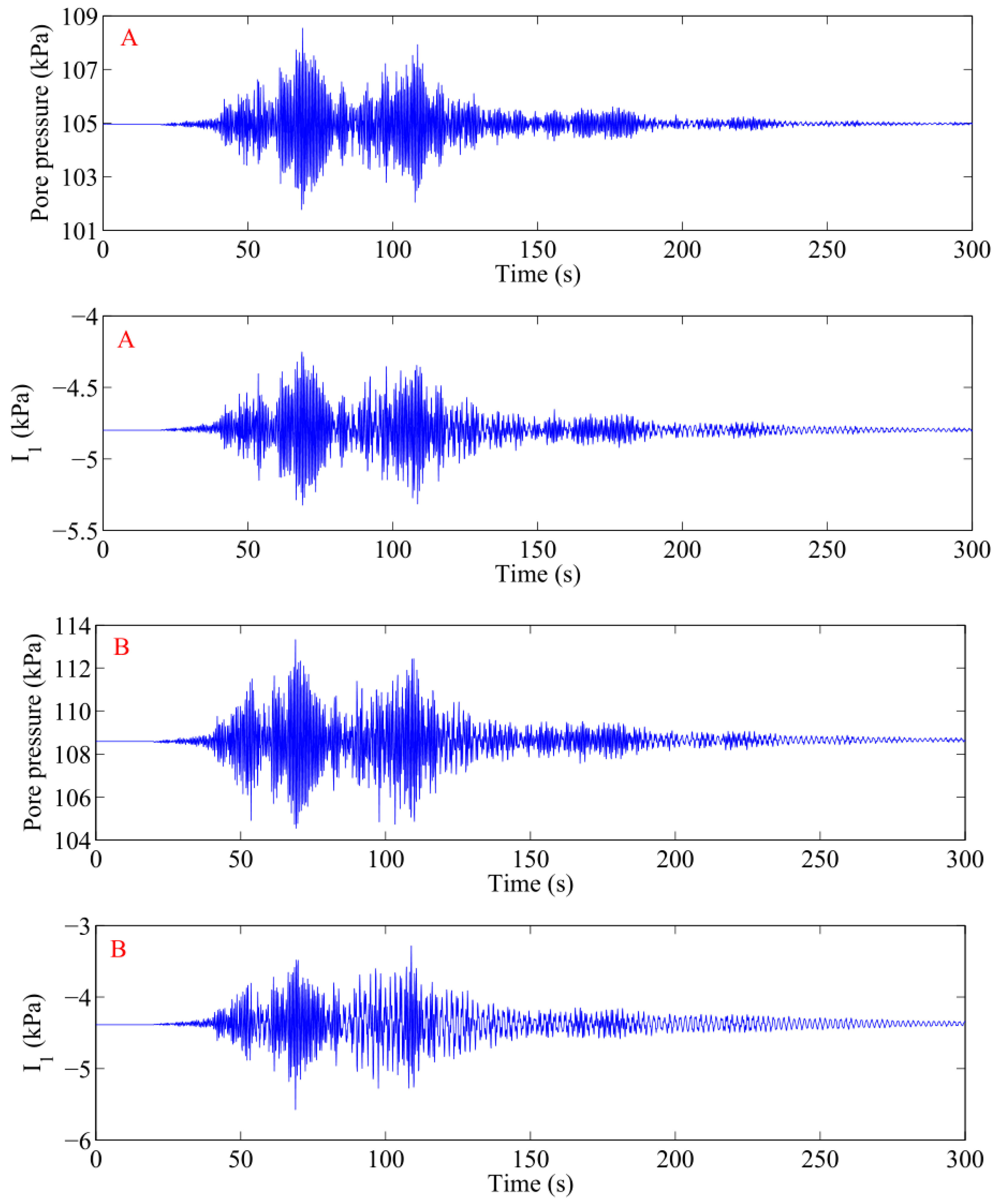
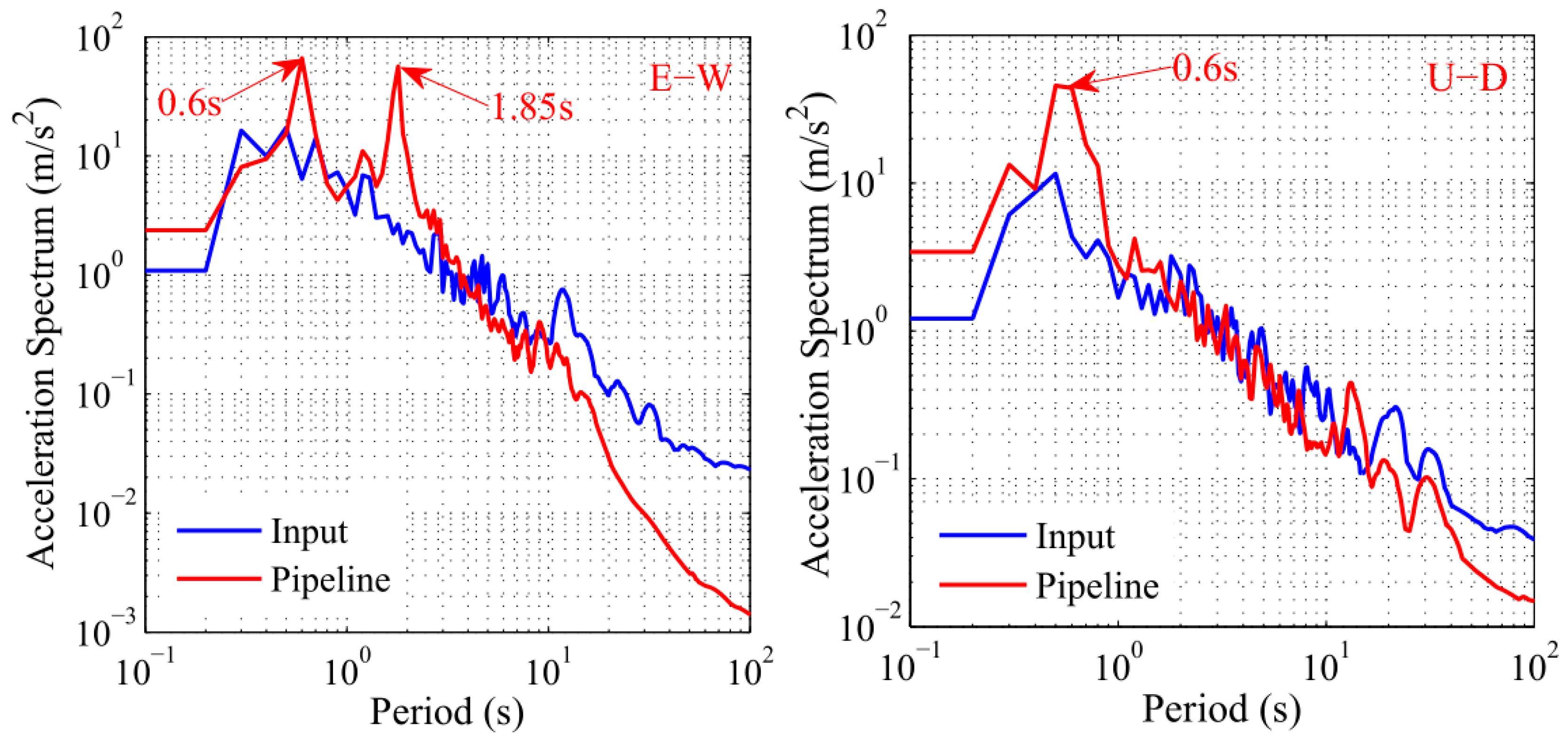
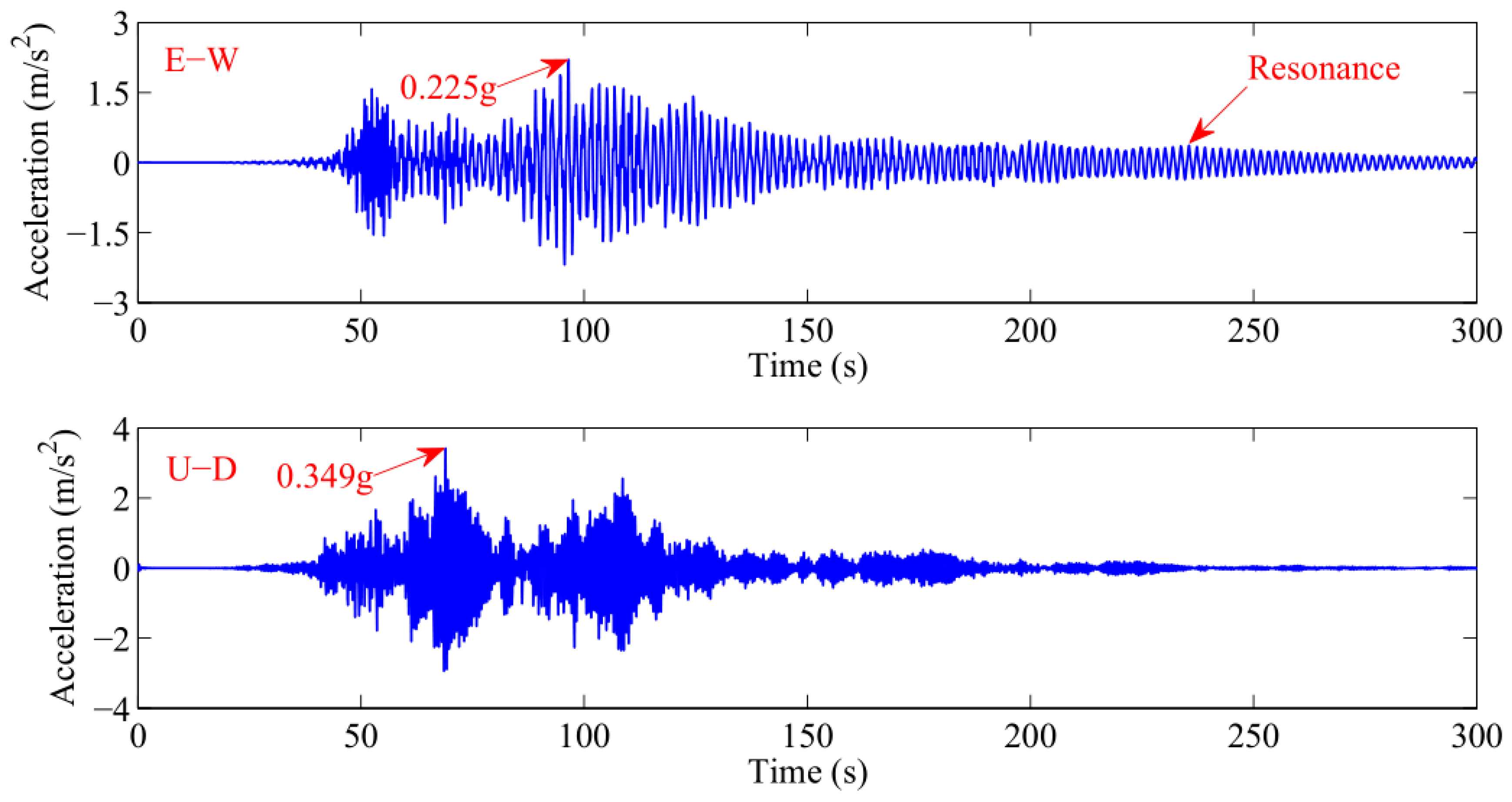
4.2. Seismic Dynamics of Pipeline
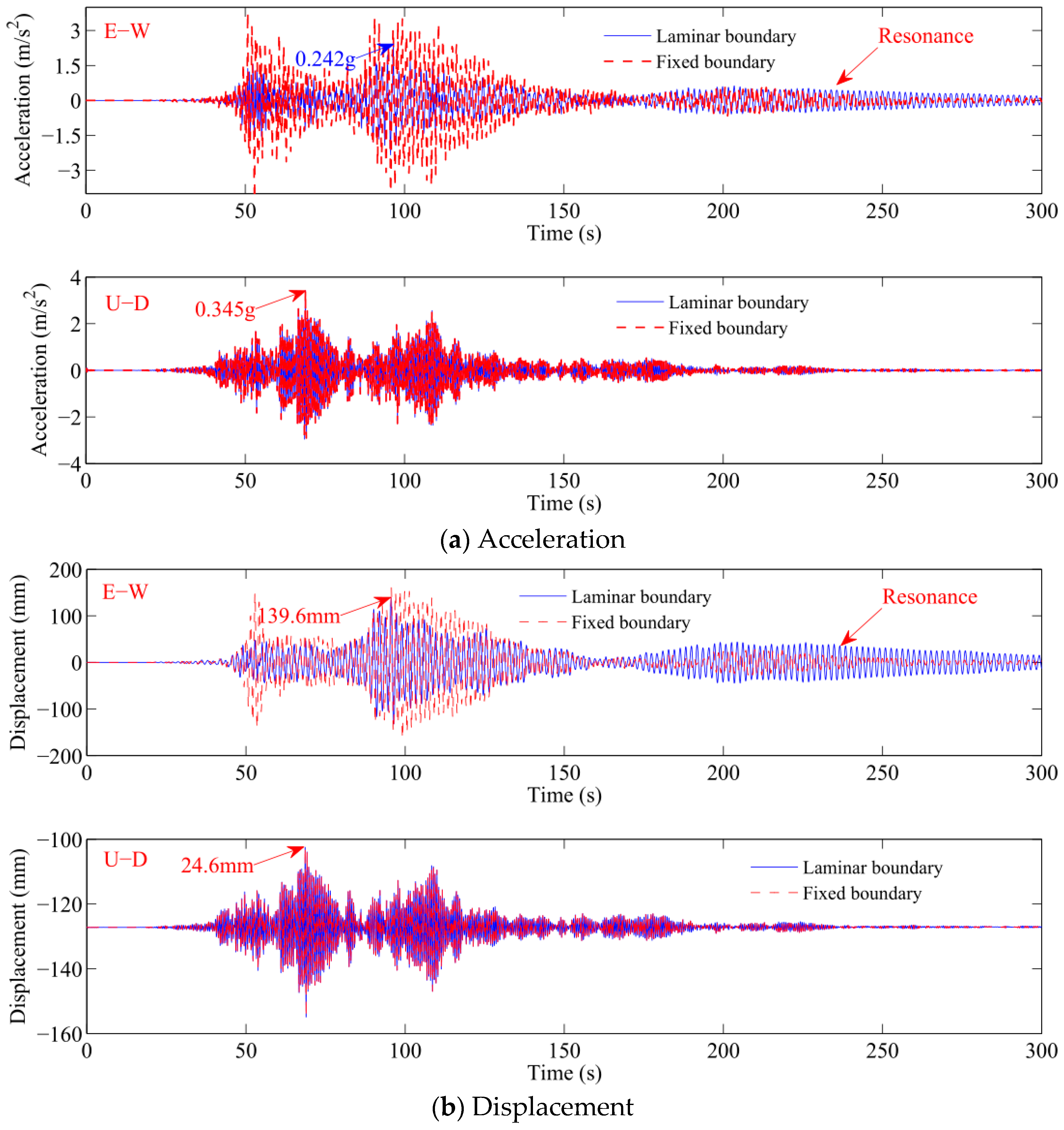
4.3. Effect of Lateral Boundary Condition
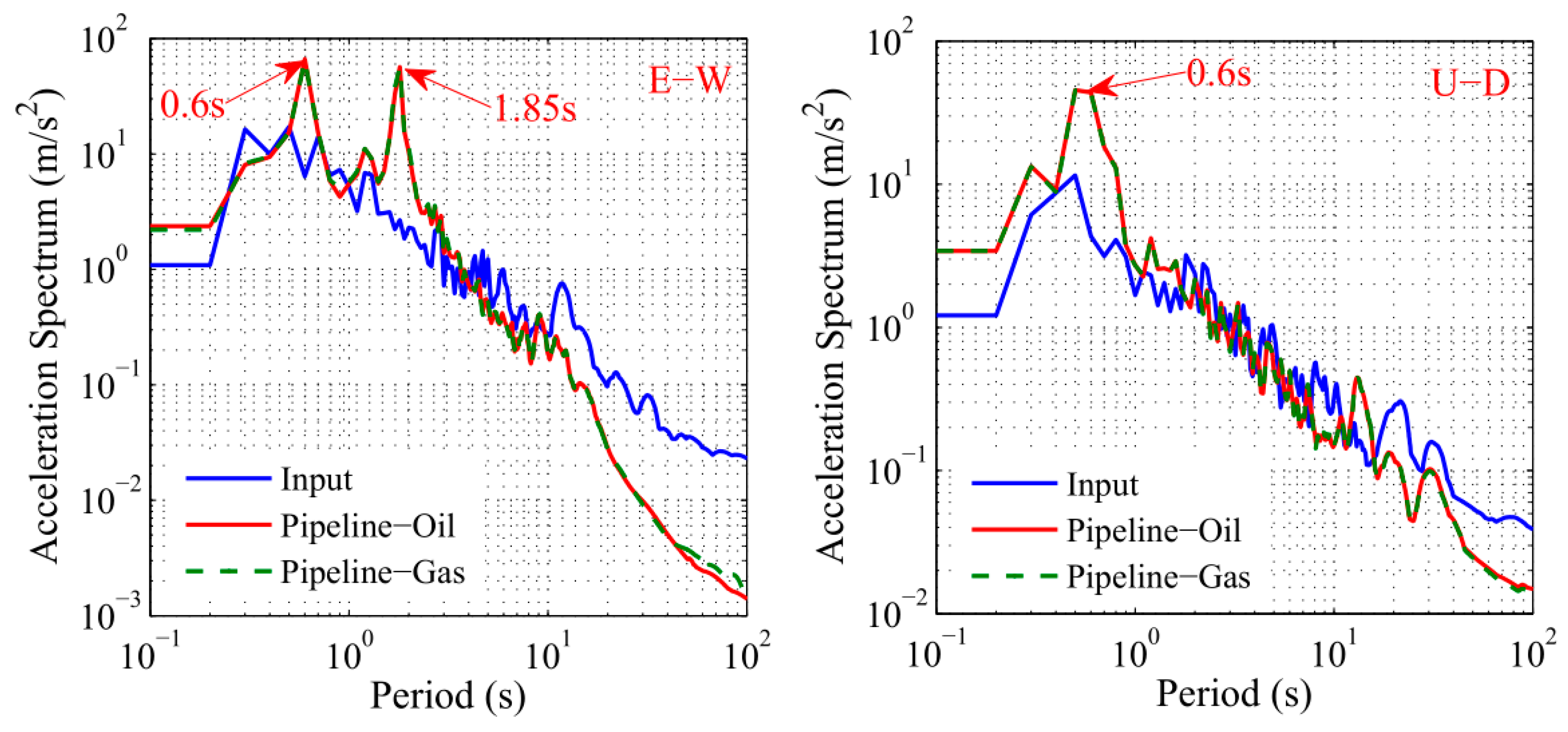
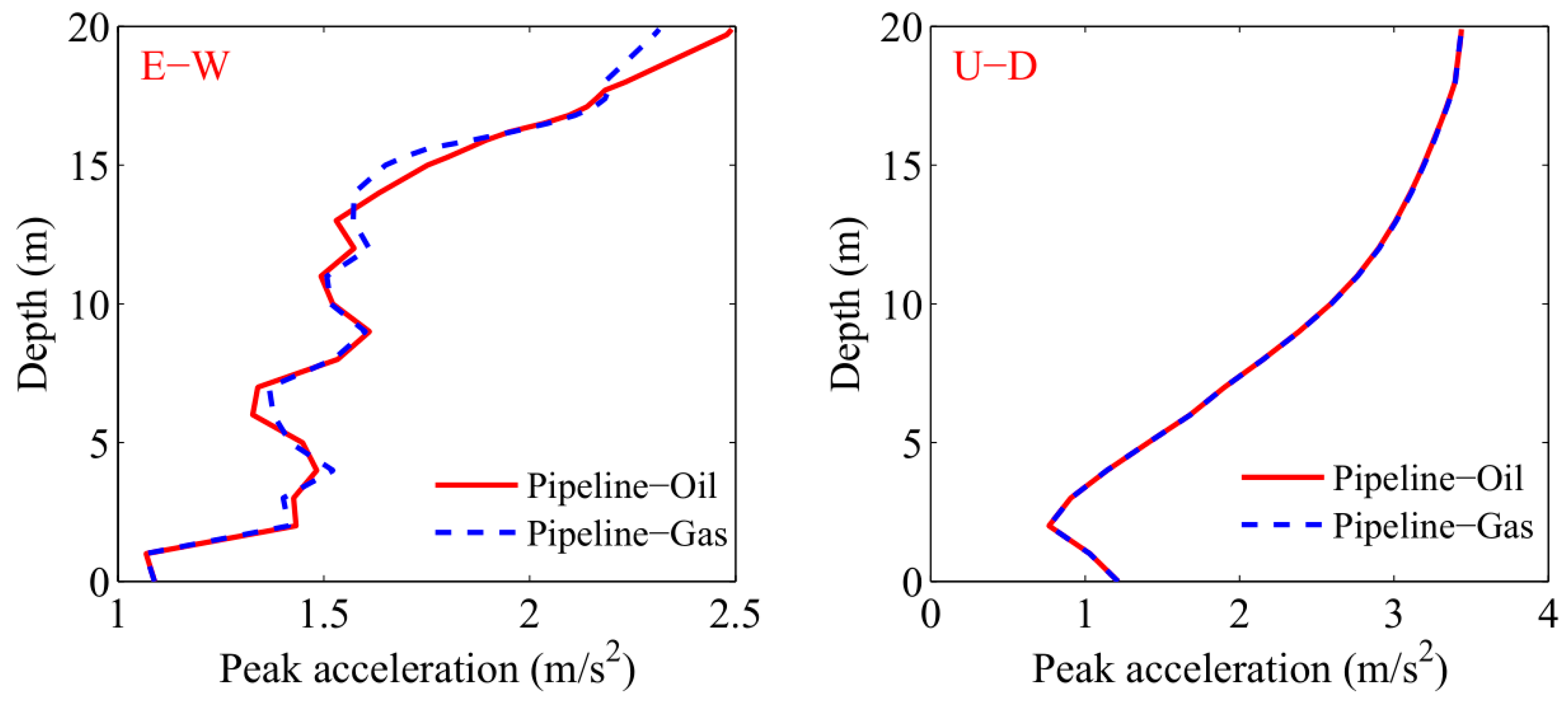
4.4. Comparison with Pipeline-Gas System
5. Conclusions
Author Contributions
Funding
Conflicts of Interest
References
- Larsen, B.E.; Fuhrman, D.R.; Sumer, B.M. Simulation of wave-plus-current scour beneath submarine pipelines. J. Waterw. Port Coast. Ocean Eng. 2016, 142, 04016003. [Google Scholar] [CrossRef]
- Kiziloz, B.; Cevik, E.; Yuksel, Y. Scour below submarine pipelines under irregular wave attack. Coast. Eng. 2013, 79, 1–8. [Google Scholar] [CrossRef]
- Bayraktar, D.; Ahmada, J.; Larsena, B.E.; Carstensena, S.; Fuhrmana, D.R. Experimental and numerical study of wave-induced backfilling beneath submarine pipelines. Coast. Eng. 2016, 118, 63–75. [Google Scholar] [CrossRef] [Green Version]
- Cheng, A.H.-D.; Liu, P.L.-F. Seepage force on a pipeline buried in a poro-elastic seabed under wave loadings. Appl. Ocean Res. 1986, 8, 22–32. [Google Scholar] [CrossRef]
- Fu, C.J.; Li, G.Y.; Zhao, T.L. Calculation of seepage force around buried pipelines under nonlinear waves. Chin. J. Geotech. Eng. 2015, 37, 932–936. [Google Scholar]
- An, H.; Cheng, L.; Zhao, M. Numerical simulation of a partially buried pipeline in a permeable seabed subject to combined oscillatory flow and steady current. Ocean Eng. 2011, 38, 1225–1236. [Google Scholar] [CrossRef]
- Mostafa, A.M.; Mizutani, N. Nonlinear wave forces on a marine pipeline buried in a sand seabed. In Proceedings of the Twelfth International Offshore and Polar Engineering Conference, Kitakyushu, Japan, 26–31 May 2002; pp. 68–75. [Google Scholar]
- Magda, W. Wave-induced uplift force on a submarine pipeline buried in a compressible seabed. Ocean Eng. 1997, 24, 551–576. [Google Scholar] [CrossRef]
- Jeng, D.-S.; Cheng, L. Wave-induced seabed instability around a buried pipeline in a poro-elastic seabed. Ocean Eng. 2002, 27, 127–146. [Google Scholar] [CrossRef]
- Wang, X.; Jeng, D.S.; Lin, Y.S. Effects of a cover layer on wave-induced pore pressure around a buried pipe in an anisotropic seabed. Ocean Eng. 2000, 27, 823–839. [Google Scholar] [CrossRef]
- Jeng, D.S. Numerical modeling for wave-seabed-pipe interaction in a non-homogeneous porous seabed. Soil Dyn. Earthq. Eng. 2001, 21, 699–712. [Google Scholar] [CrossRef]
- Gao, F.P.; Jeng, D.S.; Sekiguchi, H. Numerical study on the interaction between nonlinear wave, buried pipeline and non-homogenous porous seabed. Comput. Geotech. 2003, 30, 535–547. [Google Scholar] [CrossRef]
- Gao, F.P.; Wu, Y.X. Non-linear wave-induced transient response of soil around a trenched pipeline. Ocean Eng. 2006, 33, 311–330. [Google Scholar] [CrossRef] [Green Version]
- Luan, M.; Qu, P.; Jeng, D.S.; Guo, Y.; Yang, Q. Dynamic response of a porous seabed-pipeline interaction under wave loading: Soil-pipeline contact effects and inertial effects. Comput. Geotech. 2008, 35, 173–186. [Google Scholar] [CrossRef]
- Zhou, X.L.; Zhang, J.; Guo, J.J.; Wang, J.H.; Jeng, D.S. Cnoidal wave induced seabed response around a buried pipeline. Ocean Eng. 2015, 101, 118–130. [Google Scholar] [CrossRef]
- Zhou, X.L.; Jeng, D.S.; Yan, Y.G.; Wang, J.H. Wave-induced multi-layered seabed response around a buried pipeline. Ocean Eng. 2013, 72, 195–208. [Google Scholar] [CrossRef]
- Zhang, X.L.; Jeng, D.S.; Luan, M.T. Dynamic response of a porous seabed around pipeline under three-dimensional wave loading. Soil Dyn. Earthq. Eng. 2011, 31, 785–791. [Google Scholar] [CrossRef]
- Zhao, H.Y.; Jeng, D.S.; Guo, Z.; Zhang, J.S. Two-dimensional model for pore pressure accumulations in the vicinity of a buried pipeline. J. Offshore Mech. Arct. Eng. 2014, 136, 042001. [Google Scholar] [CrossRef]
- Zhao, K.; Xiong, H.; Chen, G.; Zhao, D.; Chena, W.; Du, X. Wave-induced dynamics of marine pipelines in liquefiable seabed. Coast. Eng. 2018, 140, 100–113. [Google Scholar] [CrossRef]
- Seed, H.B.; Rahman, M.S. Wave-induced pore pressure in relation to ocean floor stability of cohesionless soils. Mar. Geotechnol. 1978, 3, 123–150. [Google Scholar] [CrossRef]
- Martin, G.R.; Seed, H.B. One-dimensional dynamic ground response analyses. J. Geotech. Eng. ASCE 1984, 108, 935–952. [Google Scholar] [CrossRef]
- Dunn, S.L.; Vun, P.L.; Chan, A.H.C.; Damgaard, J.S. Numerical modeling of wave-induced liquefaction around pipelines. J. Waterw. Port Coast. Ocean Eng. 2006, 132, 276–288. [Google Scholar] [CrossRef]
- Zienkiewicz, O.C.; Chan, A.H.C.; Pastor, M.; Schrefler, B.A.; Shiomi, T. Computational Geomechanics with Special Reference to Earthquake Engineering; John Wiley and Sons: Chichester, UK, 1999. [Google Scholar]
- Nath, B.; Soh, C.H. Transverse seismic response analysis of offshore pipelines in proximity to the seabed. Earthq. Eng. Struct. Dyn. 1978, 6, 569–583. [Google Scholar] [CrossRef]
- Datta, T.K.; Mashaly, E.A. Transverse response of offshore pipelines to random ground motion. Earthq. Eng. Struct. Dyn. 1990, 19, 217–228. [Google Scholar] [CrossRef]
- Wang, L.R.L.; Cheng, K.M. Seismic response behavior of buried pipelines. J. Press. Vessel Technol. 1979, 101, 21–30. [Google Scholar] [CrossRef]
- Datta, S.K.; O’Leary, P.M.; Shah, A.H. Three-dimensional dynamic response of buried pipelines to incident longitudinal and shear waves. J. Appl. Mech. 1985, 52, 919–926. [Google Scholar] [CrossRef]
- Datta, T.K.; Mashaly, E.A. Seismic response of buried submarine pipelines. J. Energy Resour. Technol. 1988, 110, 208–218. [Google Scholar] [CrossRef]
- Ling, H.I.; Sun, L.X.; Liu, H.B.; Mohri, Y.; Kawabata, T. Finite element analysis of pipe buried in saturated soil deposit subject to earthquake loading. J. Earthq. Tsunami 2008, 2, 1–17. [Google Scholar] [CrossRef]
- Luan, M.T.; Zhang, X.L.; Yang, Q.; Guo, Y. Numerical analysis of liquefaction of porous seabed around pipeline fixed in space under seismic loading. Soil Dyn. Earthq. Eng. 2009, 29, 855–864. [Google Scholar]
- Zhang, X.L.; Han, Y. Numerical analysis of seismic dynamic response of saturated porous seabed around a buried pipeline. Mar. Georesour. Geotechnol. 2013, 31, 254–270. [Google Scholar] [CrossRef]
- Saeedzadeh, R.; Hataf, N. Uplift response of buried pipelines in saturated sand deposit under earthquake loading. Soil Dyn. Earthq. Eng. 2011, 31, 1378–1384. [Google Scholar] [CrossRef]
- Duan, M.L.; Mao, D.F.; Yue, Z.Y. A seismic design method for subsea pipelines against earthquake fault movement. China Ocean Eng. 2011, 25, 179–188. [Google Scholar] [CrossRef]
- Uckan, E.; Akbas, B.; Shen, J.; Rou, W.; Paolacci, F.; O’Rourke, M. A simplified analysis model for determining the seismic response of buried steel pipes at strike-slip fault crossings. Soil Dyn. Earthq. Eng. 2011, 75, 55–65. [Google Scholar] [CrossRef]
- Ling, H.I.; Mohri, Y.; Kawabata, T.; Liu, H.B.; Burke, C.; Sun, L. Centrifugal modeling of seismic behavior of large-diameter pipe in liquefiable soil. J. Geotech. Geoenviron. Eng. 2003, 129, 1092–1101. [Google Scholar] [CrossRef]
- Huang, B.; Liu, J.; Lin, P.; Ling, D. Uplifting behavior of shallow buried pipe in liquefiable soil by dynamic centrifuge test. Sci. World J. 2014, 2014, 838546. [Google Scholar] [CrossRef] [PubMed]
- Jeng, D.-S.; Ye, J.H.; Zhang, J.-S.; Liu, P.-F. An integrated model for the wave-induced seabed response around marine structures: Model, verifications and applications. Coast. Eng. 2013, 72, 1–19. [Google Scholar] [CrossRef]
- Ye, J.H.; Jeng, D.-S.; Wang, R.; Zhu, C.Q. A 3-D semi-coupled numerical model for fluid-structures-seabed-interaction (FSSI-CAS 3D): Model and verification. J. Fluids Struct. 2013, 40, 148–162. [Google Scholar] [CrossRef]
- Ye, J.H.; Jeng, D.-S.; Wang, R.; Zhu, C.-Q. Validation of a 2D semi-coupled numerical model for Fluid-Structures-Seabed Interaction. J. Fluids Struct. 2013, 42, 333–357. [Google Scholar] [CrossRef]
- Hsu, T.J.; Sakakiyama, T.; Liu, P.L. A numerical model for wave motions and turbulence flows in front of a composite breakwater. Coast. Eng. 2002, 46, 25–50. [Google Scholar] [CrossRef]
- Zienkiewicz, O.C.; Chang, C.T.; Bettess, P. Drained, undrained, consolidating and dynamic behaviour assumptions in soils. Géotechnique 1980, 30, 385–395. [Google Scholar] [CrossRef]
- Ye, J.H.; Jeng, D.-S.; Chan, A.H.C. Consolidation and dynamics of 3D unsaturated Cheng:1986p22porous seabed under rigid caisson breakwater loaded by hydrostatic pressure and wave. Sci. China-Technol. Sci. 2012, 55, 2362–2376. [Google Scholar] [CrossRef]
- He, K.; Huang, T.; Ye, J. Stability analysis of a composite breakwater at Yantai port, China: An application of FSSI-CAS-2D. Ocean Eng. 2018, 168, 95–107. [Google Scholar] [CrossRef]
- Ye, J.H.; Wang, G. Seismic dynamics of offshore breakwater on liquefiable seabed foundation. Soil Dyn. Earthq. Eng. 2015, 76, 86–99. [Google Scholar] [CrossRef]
- Zhang, M.S.; Liu, H.J.; Li, X.D.; Jia, Y.G.; Wang, X.H. Study of liquefaction of silty soil and mechanism of development of hard layer under wave actions at Yellow River Estuary. Rock Soil Mech. 2009, 30, 3347–3352. [Google Scholar]
- Yang, G.; Ye, J. Wave & current-induced progressive liquefaction in loosely deposited seabed. Ocean Eng. 2017, 142, 303–314. [Google Scholar]
- Yang, G.X.; Ye, J.H. Nonlinear standing wave-induced liquefaction in loosely deposited seabed. Bull. Eng. Geol. Environ. 2018, 77, 205–223. [Google Scholar] [CrossRef]


| Parameter | Seabed | Pipeline | Crude Oil |
|---|---|---|---|
| Elastic modulus E (MPa) | 20 | 200 × 103 | 1 × 10⁻¹ |
| Poisson’s ratio v | 0.33 | 0.25 | 0.5 |
| Porosity n | 0.4 | 0 | 1.0 |
| Permeability k (m/s) | 1.0 × 10⁻⁵ | 0 | 1.0 × 10⁻¹ |
| Saturation Sr (%) | 98 | 0 | 100 |
| Density ρ (g/cm3) | 2.65 | 7.85 | 0.85 |
© 2019 by the authors. Licensee MDPI, Basel, Switzerland. This article is an open access article distributed under the terms and conditions of the Creative Commons Attribution (CC BY) license (http://creativecommons.org/licenses/by/4.0/).
Share and Cite
Zhang, Y.; Ye, J.; He, K.; Chen, S. Seismic Dynamics of Pipeline Buried in Dense Seabed Foundation. J. Mar. Sci. Eng. 2019, 7, 190. https://doi.org/10.3390/jmse7060190
Zhang Y, Ye J, He K, Chen S. Seismic Dynamics of Pipeline Buried in Dense Seabed Foundation. Journal of Marine Science and Engineering. 2019; 7(6):190. https://doi.org/10.3390/jmse7060190
Chicago/Turabian StyleZhang, Yan, Jianhong Ye, Kunpeng He, and Songgui Chen. 2019. "Seismic Dynamics of Pipeline Buried in Dense Seabed Foundation" Journal of Marine Science and Engineering 7, no. 6: 190. https://doi.org/10.3390/jmse7060190