Simulation Techniques for Design and Control of a Waste Heat Recovery System in Marine Natural Gas Propulsion Applications


Abstract
:1. Introduction
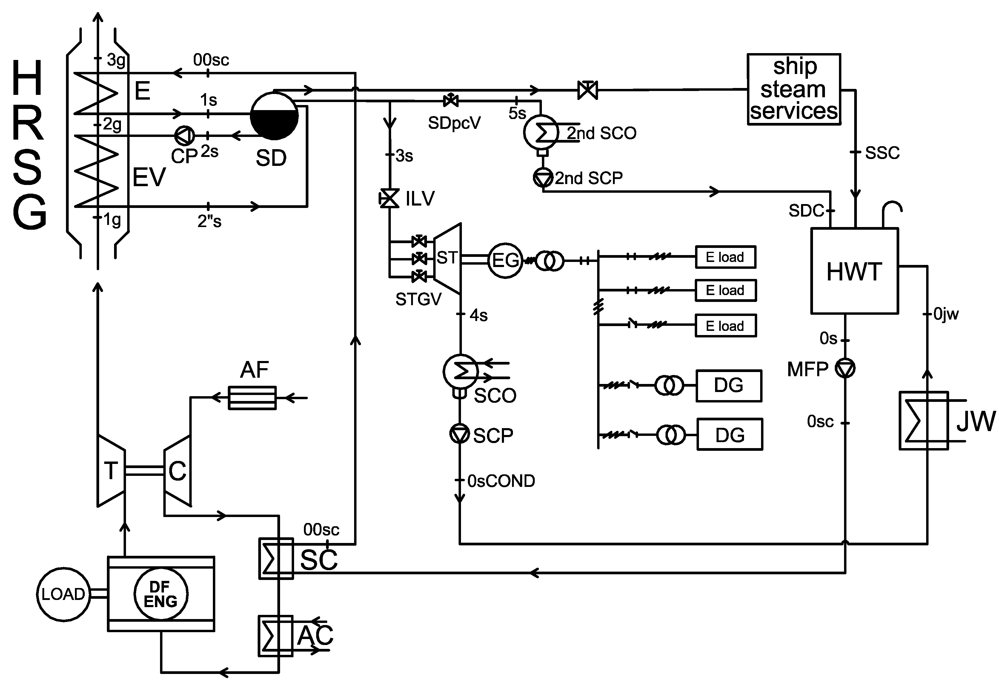
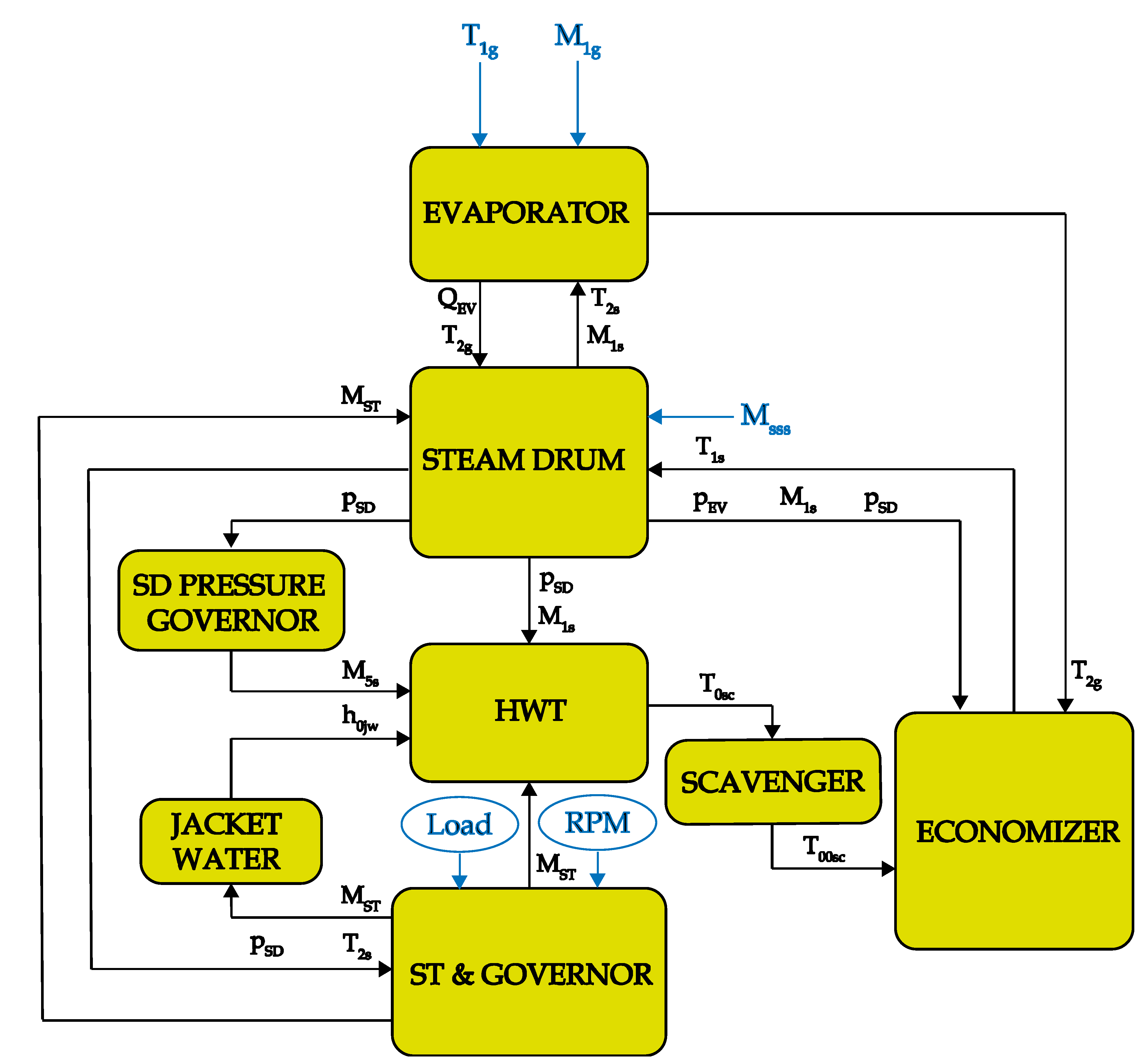
2. Simulation Model
2.1. Main Basic Equations
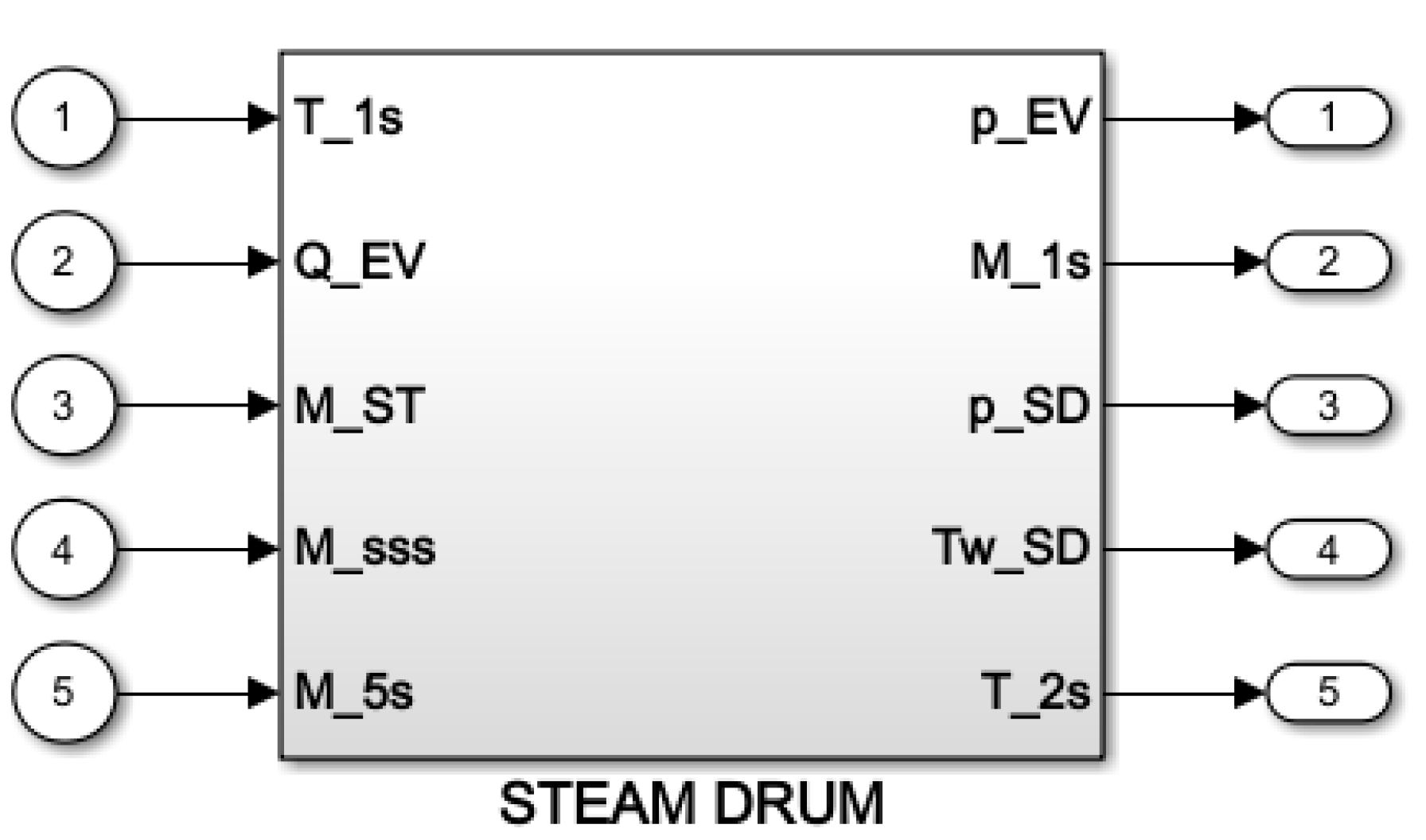
2.2. Steam Turbine Modeling
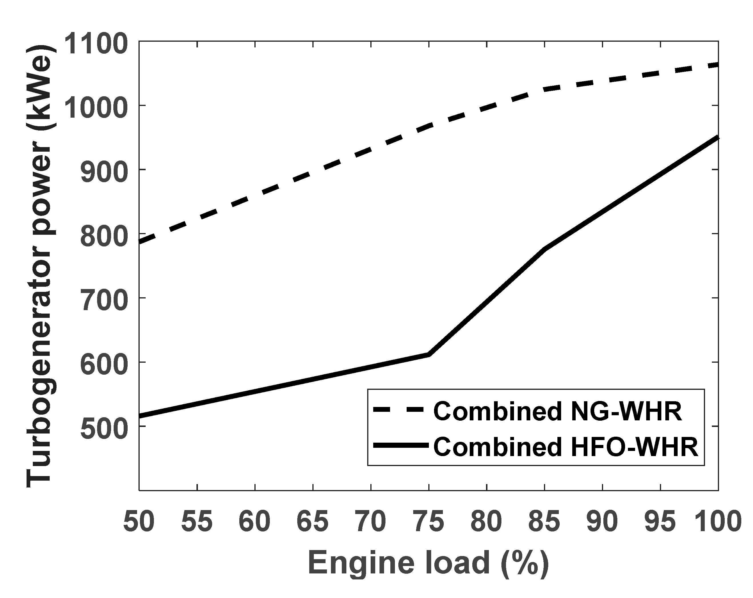
3. Steady-State Performance
4. ST Governor Design: Methodology and Application
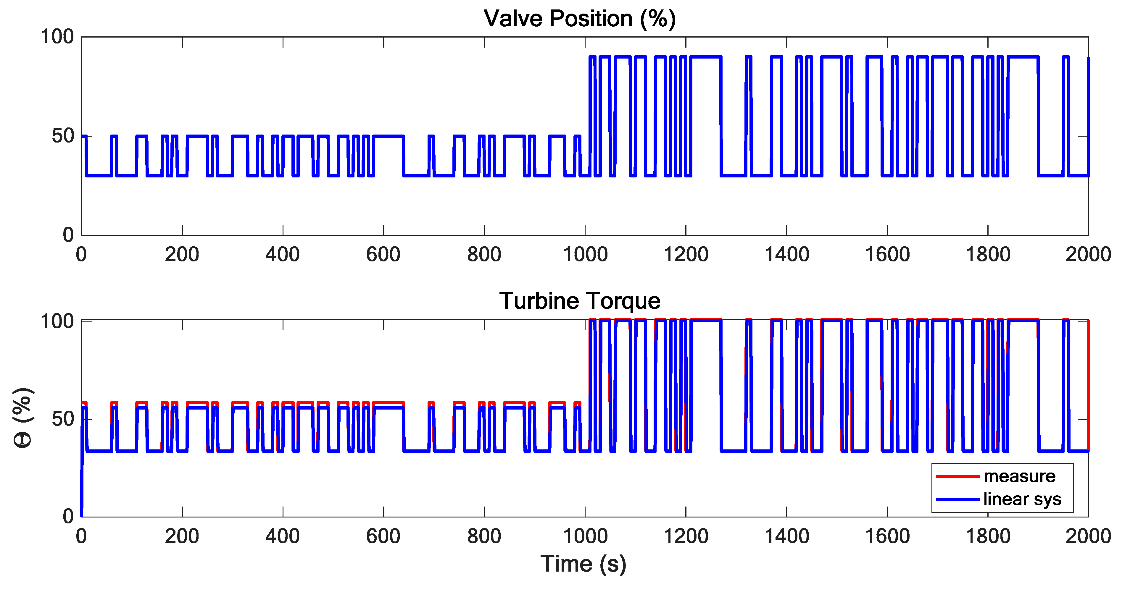
4.1. System Identification
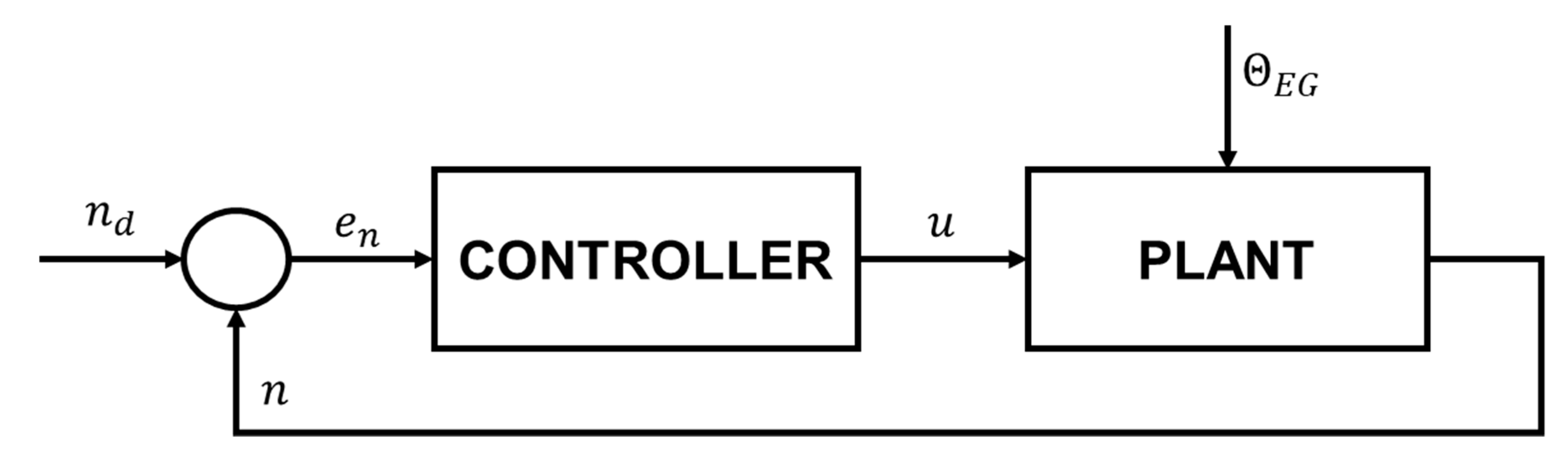
4.2. Controller Design and Synthesis
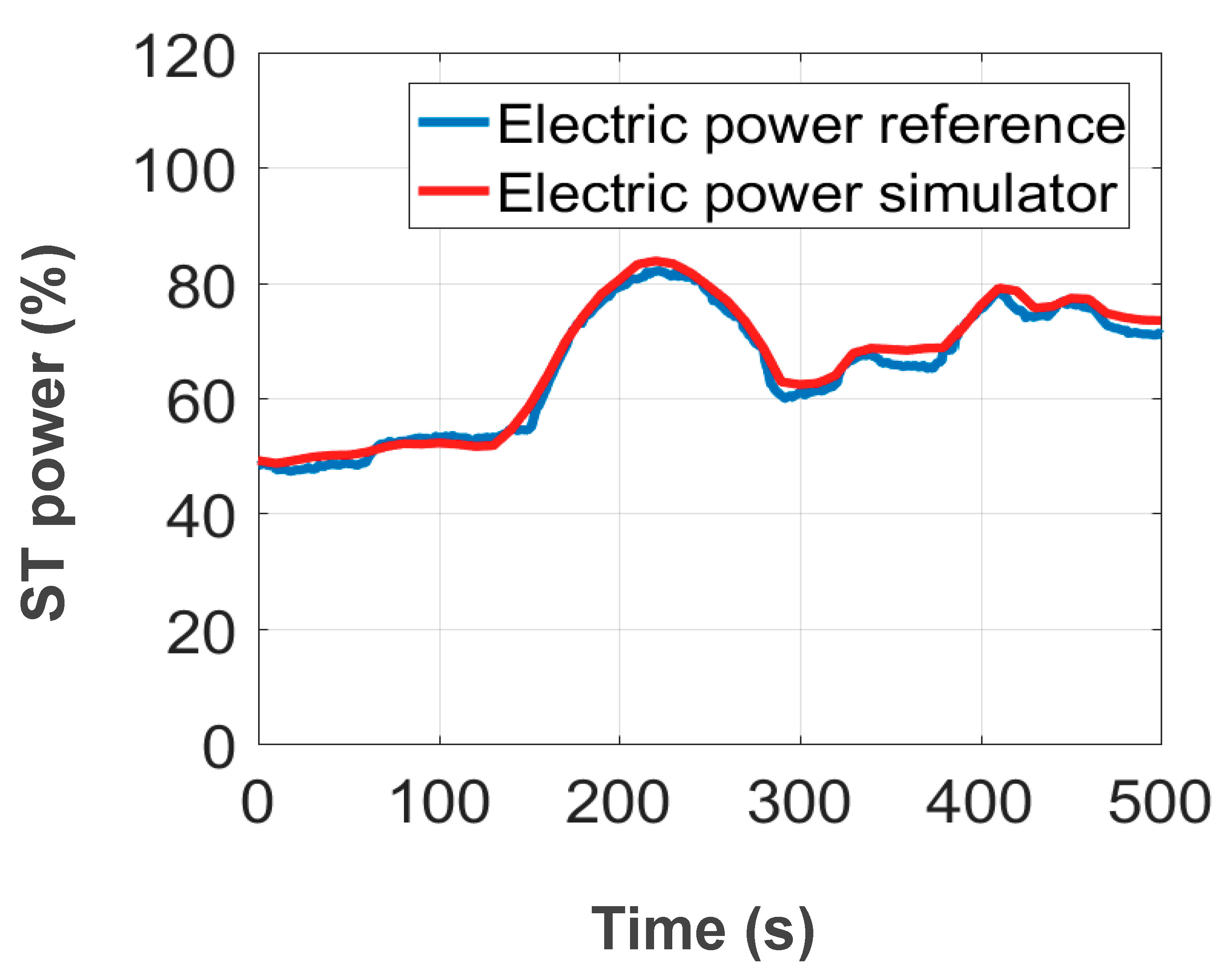
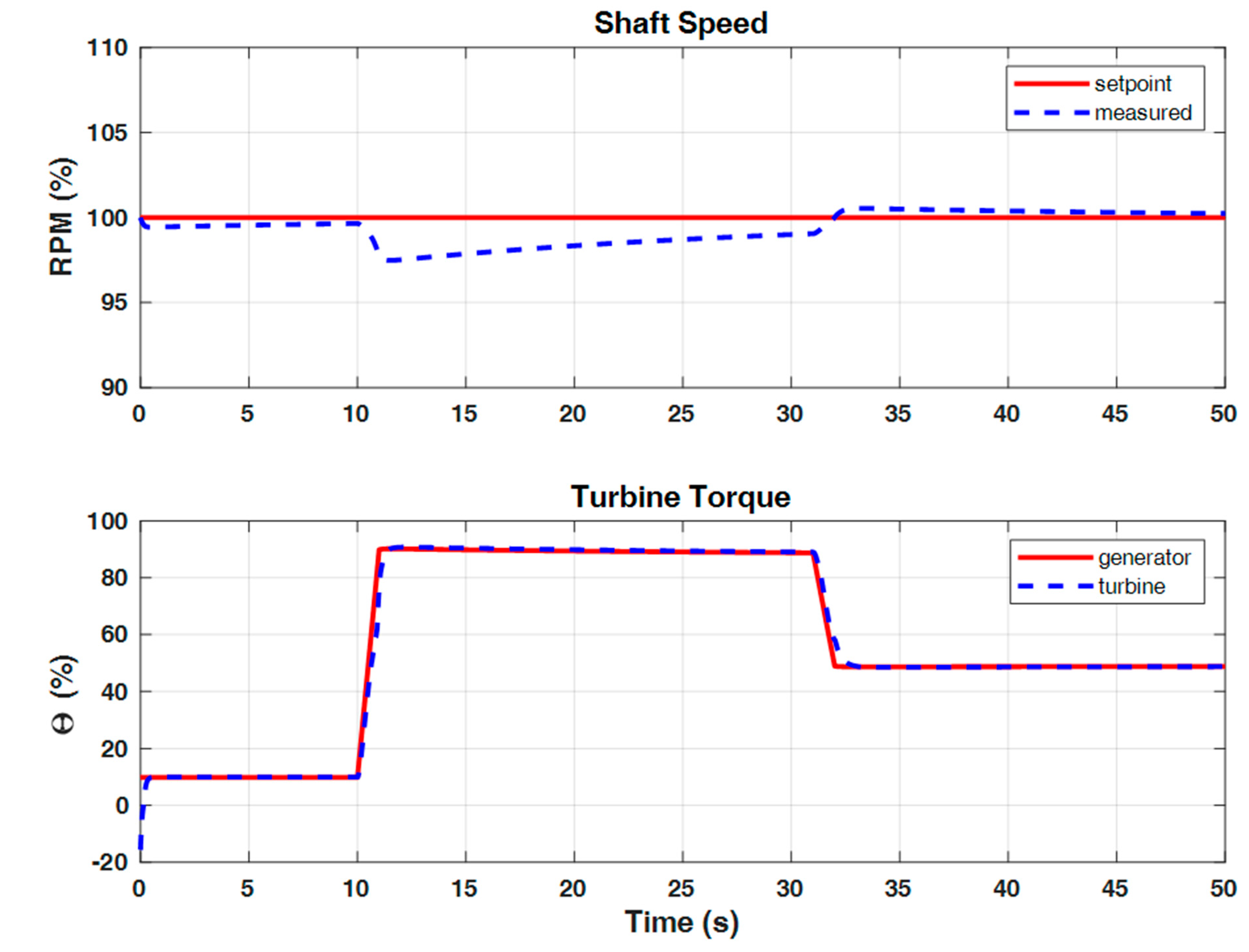
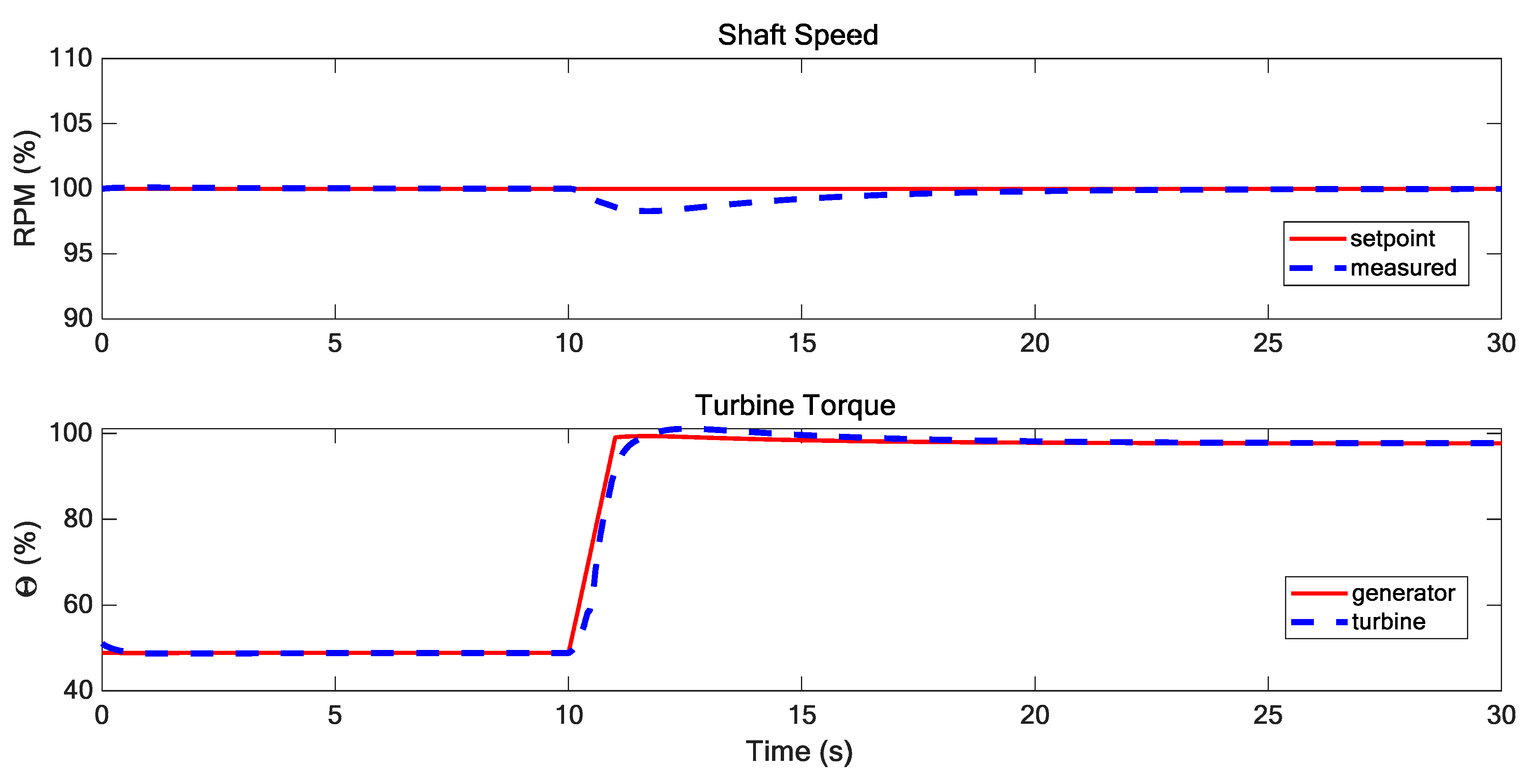
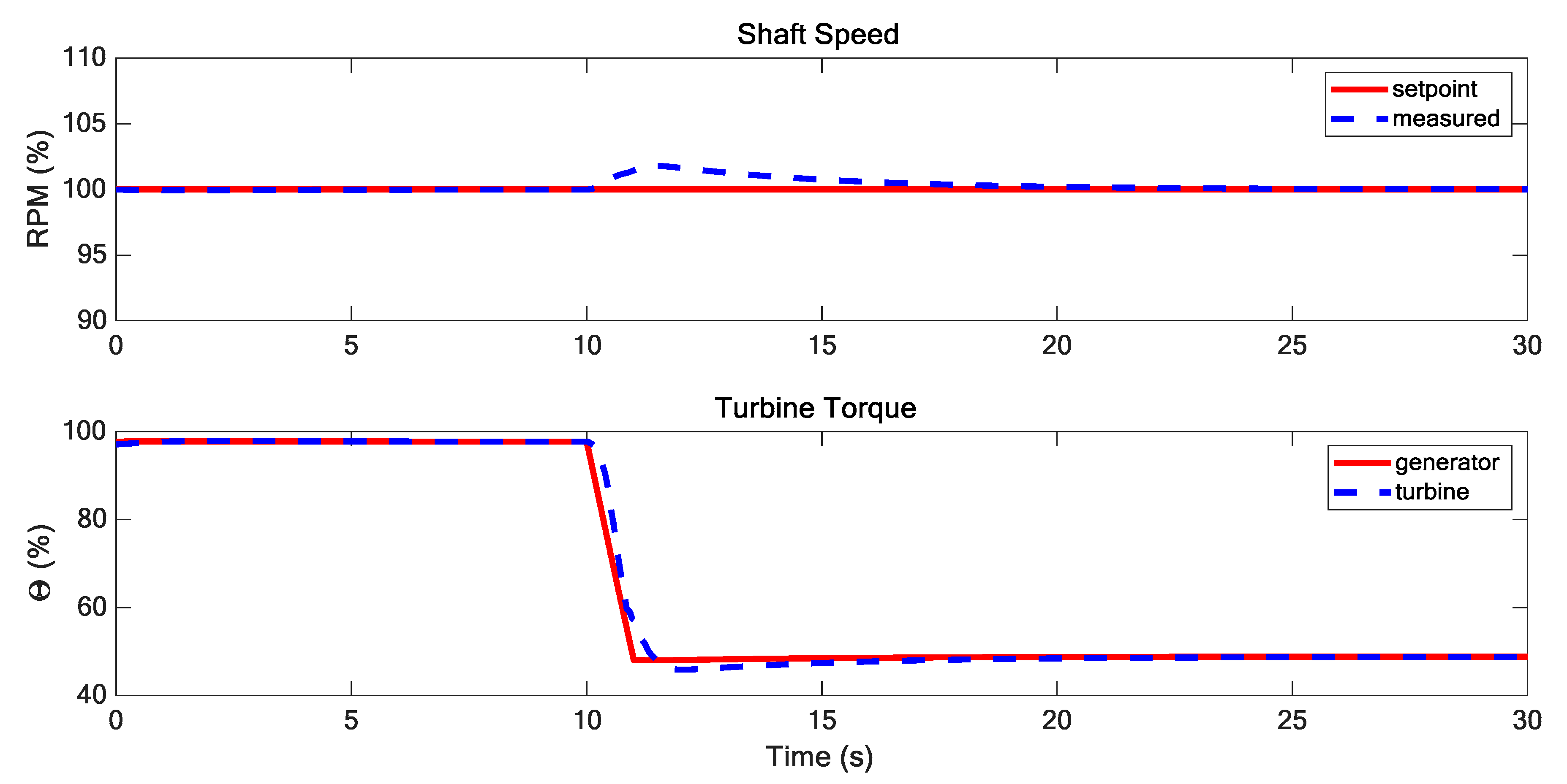
5. Dynamic Simulation Results
6. Conclusions
Author Contributions
Funding
Acknowledgments
Conflicts of Interest
References
- International Maritime Organization (IMO). Report of the Marine Environment Protection Committee (MEPC) on its 57th Session; International Maritime Organization: London, UK, 2008. [Google Scholar]
- International Maritime Organization (IMO). International Convention for the Prevention of Pollution from Ships (MARPOL) Annex VI; International Maritime Organization: London, UK, 2011. [Google Scholar]
- International Maritime Organization (IMO). Marine Environment Protection Committee (MEPC), 66th Session; International Maritime Organization: London, UK, 2014. [Google Scholar]
- International Maritime Organization (IMO). Interim Guidelines on the Method of Calculation of the Energy Efficiency Design Index (EEDI) for New Ships; In MEPC 1/Circ: 681; International Maritime Organization: London, UK, 2009. [Google Scholar]
- International Maritime Organization (IMO). Guidelines to the Method of Calculation of the Attained Energy Efficiency Design Index (EEDI) for New Ships; In MEPC 212 (63/23); Annex 8; International Maritime Organization: London, UK, 2012. [Google Scholar]
- Altosole, M.; Figari, M.; Martinelli, L.; Raimondi, M. Hybrid propulsion by gas engines for an ASD harbour tug. In Proceedings of the 17th International Conference on Ships and Shipping Research, NAV 2012, Naples, Italy, 17–19 October 2012. [Google Scholar]
- Altosole, M.; Buglioni, G.; Figari, M. Alternative propulsion technologies for fishing vessels: A case study. Int. Rev. Mech. Eng. 2014, 8, 296–301. [Google Scholar]
- Pedersen, M.F. Emission Standards; DieselNet: Mississauga, ON, Canada, 2015. [Google Scholar]
- Altosole, M.; Benvenuto, G.; Campora, U.; Laviola, M.; Zaccone, R. Simulation and performance comparison between diesel and natural gas engines for marine applications. Proc. Inst. Mech. Eng. Part. M J. Eng. Marit. Environ. 2017, 231, 690–704. [Google Scholar] [CrossRef]
- Schmid, H. Less emissions through waste heat recovery. In Proceedings of the Green Ship Technology Conference, London, UK, 28–29 April 2004. [Google Scholar]
- Theotokatos, G.; Livanos, G. Exhaust gas waste heat recovery in marine propulsion plants. In Proceedings of the 14th International Conference on Maritime Association of Mediterranean, IMAM 2011, Genova, Italy, 13–16 September 2011; Soares, C.G., Rizzuto, E., Eds.; CRC Press/Balkema: Boca Raton, FL, USA, 2012. [Google Scholar]
- Altosole, M.; Laviola, M.; Trucco, A.; Sabattini, A. Waste heat recovery systems from marine diesel engines: Comparison between new design and retrofitting solutions. In Maritime Technology and Engineering. In Proceedings of the 2nd International Conference on Maritime Technology and Engineering, MARTECH 2014, Lisbon, Portugal, 14–17 October 2014; Soares, C.G., Santos, T.A., Eds.; CRC Press/Balkema: Boca Raton, FL, USA, 2015. [Google Scholar]
- Altosole, M.; Benvenuto, G.; Campora, U.; Laviola, M.; Trucco, A. Waste heat recovery from marine gas turbines and diesel engines. Energies 2017, 10, 718. [Google Scholar] [CrossRef]
- Livanos, G.A.; Theotokatos, G.; Pagonis, D.N. Techno-economic investigation of alternative propulsion plants for Ferries and RoRo ships. Energy Convers. Manag. 2014, 79, 640–651. [Google Scholar] [CrossRef] [Green Version]
- Altosole, A.; Campora, U.; Laviola, M.; Zaccone, R. Waste heat recovery from dual-fuel marine engines. In Maritime Transportation and Harvesting of Sea Resources. In Proceedings of the 17th International Congress of the International Maritime Association of the Mediterranean, IMAM 2017, Lisbon, Portugal, 9–11 October 2017; Soares, C.G., Teixeira, A.P., Eds.; CRC Press/Balkema: Boca Raton, FL, USA, 2017. [Google Scholar]
- Altosole, A.; Campora, U.; Savio, S. Improvements of the ship energy efficiency by a steam powered turbogenerator in LNG propulsion applications. In Proceedings of the International Symposium on Power Electronics, SPEEDAM 2018, Amalfi, Italy, 20–22 June 2018; pp. 449–455. [Google Scholar]
- Altosole, A.; Campora, U.; Laviola, M.; Zaccone, R. High Efficiency waste heat recovery from dual fuel marine engines. In technology and science for the ships of the future. In Proceedings of the 19th International Conference on Ship and Maritime Research, NAV 2018, Trieste, Italy, 20–22 June 2018; Marino, A., Bucci, V., Eds.; Associazione Italiana di Tecnica Navale: Genoa, Italy, 2018. [Google Scholar]
- Man Diesel & Turbo. Waste Heat Recovery System (WHRS) for Reduction of Fuel Consumption, Emissions and EEDI; Man Diesel & Turbo: Copenhagen, Denmark, 2011. [Google Scholar]
- Lucia, U.; Grisolia, G. Exergy inefficiency: An indicator for sustainable development analysis. Energy Rep. 2019, 5, 62–69. [Google Scholar] [CrossRef]
- Altosol, M.; Figari, M.; Bagnasco, A.; Maffioletti, L. Design and test of the propulsion control of the aircraft carrier “Cavour” using real-time hardware in the loop simulation. In Proceedings of the SISO European Simulation Interoperability Workshop 2007, EURO SIW 2007, Genoa, Italy, 18–20 June 2007; pp. 67–74. [Google Scholar]
- Altosole, M.; Benvenuto, G.; Figari, M.; Campora, U.; Bagnasco, A.; D’Arco, S.; Giuliano, M.; Giuffra, V.; Spadoni, A.; Zanichelli, A.; et al. Real time simulation of the propulsion plant dynamic behaviour of the Aircraft Carrier “Cavour”. In Proceedings of the 9th International Naval Engineering Conference and Exhibition: Embracing the Future, INEC 2008, Hamburg, Germany, 1–3 April 2008. [Google Scholar]
- Michetti, S.; Ratto, M.; Spadoni, A.; Figari, M.; Altosole, M.; Marcilli, G. Ship Control system wide integration and the use of dynamic simulation techniques in the Fremm project. In Proceedings of the International Conference on Electrical Systems for Aircraft, Railway and Ship Propulsion, ESARS 2010, Bologna, Italy, 19–21 October 2010. [Google Scholar]
- Altosole, M.; Benvenuto, G.; Figari, M.; Campora, U. Real-time simulation of a COGAG naval ship propulsion system. In Maritime Industry, Ocean Engineering and Coastal Resources. In Proceedings of the 12th International Congress of the International Maritime Association of the Mediterranean, IMAM 2007, Varna, Bulgaria, 2–6 September 2007; pp. 331–337. [Google Scholar]
- Altosole, M.; Martelli, M. Propulsion control strategies for ship emergency manoeuvres. Ocean Eng. 2017, 137, 99–109. [Google Scholar] [CrossRef]
- Marchelli, L. Modellazione Numerica del Comportamento Dinamico di una Turbina a Vapore per Applicazioni Navali. Master’s Thesis, University of Genova, Genova, Italy, 2018. [Google Scholar]
- Shin, J.Y.; Jeon, Y.J.; Maeng, D.J.; Kim, J.S.; Ro, S.T. Analysis of the dynamic characteristics of a combined-cycle power plant. Energy 2002, 27, 1085–1098. [Google Scholar] [CrossRef]
- MAN Energy Solutions. 51/60DF Project Guide; MAN Energy Solutions: Augsburg, Germany, 2014. [Google Scholar]
- RINA. Rules for the Classification of Ships; Part C, Chapter 2, Section 2; RINA: Genoa, Italy, 2017. [Google Scholar]
- Alessandri, A.; Donnarumma, S.; Vignolo, S.; Figari, M.; Martelli, M.; Chiti, R.; Sebastiani, L. System control design of autopilot and speed pilot for a patrol vessel by using LMIs. Towards Green Mar. Technol. Transp. 2015, 577–583. [Google Scholar] [CrossRef]


| Performance Data | DF Engine | Steam Turbine |
|---|---|---|
| Maximum continuous power (MW) | 17.55 | 1.00 |
| Maximum continuous speed (rpm) | 500 | 10,400 |
| Performance Data | LNG Mode | HFO Mode |
|---|---|---|
| SD pressure [bar] | 8 | 8 |
| HRSG outlet gas temperature [°C] | 157 | 171 |
| Ship users steam flow rate [kg/s] | 0.15 | 0.38 |
| ST steam flow rate [kg/s] | 2.06 | 1.30 |
| Turbogenerator power [kWe] | 968 | 611 |
© 2019 by the authors. Licensee MDPI, Basel, Switzerland. This article is an open access article distributed under the terms and conditions of the Creative Commons Attribution (CC BY) license (http://creativecommons.org/licenses/by/4.0/).
Share and Cite
Altosole, M.; Campora, U.; Donnarumma, S.; Zaccone, R. Simulation Techniques for Design and Control of a Waste Heat Recovery System in Marine Natural Gas Propulsion Applications. J. Mar. Sci. Eng. 2019, 7, 397. https://doi.org/10.3390/jmse7110397
Altosole M, Campora U, Donnarumma S, Zaccone R. Simulation Techniques for Design and Control of a Waste Heat Recovery System in Marine Natural Gas Propulsion Applications. Journal of Marine Science and Engineering. 2019; 7(11):397. https://doi.org/10.3390/jmse7110397
Chicago/Turabian StyleAltosole, Marco, Ugo Campora, Silvia Donnarumma, and Raphael Zaccone. 2019. "Simulation Techniques for Design and Control of a Waste Heat Recovery System in Marine Natural Gas Propulsion Applications" Journal of Marine Science and Engineering 7, no. 11: 397. https://doi.org/10.3390/jmse7110397