Article

Investigation of Focusing Wave Properties in a Numerical Wave Tank with a Fully Nonlinear Potential Flow Model

Department of Civil and Environmental Engineering, Norwegian University of Science and Technology, 7491 Trondheim, Norway
*
Author to whom correspondence should be addressed.
These authors contributed equally to this work.
J. Mar. Sci. Eng. 2019, 7(10), 375; https://doi.org/10.3390/jmse7100375
Submission received: 1 August 2019 / Revised: 9 October 2019 / Accepted: 10 October 2019 / Published: 21 October 2019
(This article belongs to the Special Issue Computational Fluid Dynamics for Ocean Surface Waves)

Abstract

:
Nonlinear wave interactions and superpositions among the different wave components and wave groups in a random sea sometimes produce rogue waves with extremely large wave heights that appear unexpectedly. A good understanding of the generation and evolution of such extreme wave events is of great importance for the analysis of wave forces on marine structures. A fully nonlinear potential flow (FNPF) model is proposed in the presented paper to investigate the different factors that influence the wave focusing location, focusing time and focusing wave height in a numerical wave tank. Those factors include wave steepness, spectrum bandwidth, wave generation method, focused wave spectrum, and wave spreading functions. The proposed model solves the Laplace equation together with the boundary conditions on a σ -coordinate grid using high-order discretisation schemes on a fully parallel computational framework. The model is validated against the focused wave experiments and thereafter used to obtain insights into the effects of the different factors. It is found that the wave steepness contributes to changing the location and time of focus significantly. Spectrum bandwidth and directional spreading affect the focusing wave height and profile, for example, a wider bandwidth and a wider directional spread lead to a lower focusing wave height. A Neumann boundary condition represents the nonlinearity of the wave groups better than a relaxation method for wave generation.

1. Introduction

Random seas consist of many incident wave components of different amplitudes, frequencies and phases. The nonlinear interactions among them may result in extreme waves that are much higher than that expected from the sea state in the region. Such large and unexpected extreme waves can exert tremendous forces on offshore structures. Understanding the generation and evolution of such waves is important for determining the wave loads on marine structures. One of the most renowned extreme events is the ‘New Year Wave’ recorded at the Draupner platform [1] where a maximum wave height of nearly 26 m was observed in a sea state with a measured significant wave height of 12 m . Retrospectively, many efforts have been made to generate and reproduce such extreme events in both physical experiments and numerical wave tanks. Among those efforts, focused wave groups are considered an efficient method to replicate extreme wave events.
Due to the stochastic nature of the sea state and extreme events, the basis for the generation of focused waves is the irregular wave theory. Lindgren [2] presented a theoretical explanation for wave generation through empirically studying the propagation of irregular wave groups. Based on his results, Tromans et al. [3] suggested a practical spectrum for focused wave groups. The spectrum has a shape that is proportional to the auto-correlation function of the underlying random processes. This type of compact wave spectrum was later named the NewWave model. The NewWave model is based on the linear wave theory and wave spectra such as the JONSWAP and PM spectrum can be used to generate the irregular wave components for linear superposition. The NewWave method has been successfully applied to investigate irregular large waves both in deep [4] and intermediate water depths [5]. The method has also been used for the study of directional irregular seas and three-dimensional (3D) wave focusing in spreading seas [4,6,7]. Recently, researchers have further extended the NewWave theory to coastal applications in the shallow water domain, for example, wave run-up and flow kinematics at plane beaches [8,9] and focused wave overtopping and forces on seawalls [10,11,12,13,14]. Another method for extreme wave generation is to use the transient wave packet approach, which has been validated during an experimental study in a wave flume [15]. The approach was later improved with increased flexibility, allowing a prediction of the wave train at any instant and location in a wave tank [16]. It was further optimised to avoid premature breaking by adjusting the high-frequency components [17]. Compared to the NewWave theory, the spectrum for the wave packet has a wider bandwidth and consists of more harmonic components of lower amplitudes relative to the focusing wave height. Consequently, a larger focusing wave height can be achieved and premature breaking is avoided.
Using different wave focusing theories, researchers have conducted many experiments to investigate different aspects of the evolution of focusing wave groups. Ning et al. [18] performed an experiment in a wave flume to study the propagation of transient focusing wave groups with a range of different steepness. It is shown that the focusing point in time and space changes with varying wave steepnesses. Clauss and Steinhagen [19] reported an experimental study on the evolution of a wave packet at the Large Wave Flume (GWK) in Hannover and demonstrated a similar finding. Sriram et al. [20] investigated the evolution of a focused wave packet in intermediate and deep water conditions using different paddle displacements for a piston-type wavemaker. The results, using second-order corrected paddle motion and linear paddle motion, were compared and it was found that the difference is more prominent for a broadband spectrum. Bai et al. [21] reported an experiment to generate focused waves in a wave flume and used the measured data for the validation of a numerical model.
Taylor and Williams [5] analyzed the data set from the WACSIS measurement program [22]. The authors paid special attention to the average shape of large crests and troughs and the vertical and horizontal asymmetry. It was shown that the NewWave theory fits the average shape of large waves well when the trough-crest asymmetry is accounted for. Buldakov et al. [23] introduced a linearized amplitude spectrum methodology following the NewWave theory to produce focused waves up to weak breaking waves in a physical wave flume. They found that the steepness of the limiting breaking wave depends strongly on the choice of the wave group spectrum. Focused wave group interaction with offshore and coastal structures and the impact forces were also investigated in several experiments [24,25]. In a 3D wave basin, Johannessen and Swan [7] performed a laboratory study on the influence of directionality on the transient focusing wave groups in a spreading sea. The experiments prove the effectiveness of the focusing wave theories and provided fundamental insights into the generation and evolution of focused waves. However, experiments were also limited by the capability of continuous measurement. Wave focusing is a transient phenomenon with a short duration, and therefore demands more dense measurements.
Many numerical models have been employed to investigate focusing wave groups. Ning et al. [18] used the local surface elevation measurements from a physical experiment to drive the numerical solution in their numerical model using a high-order boundary element method (HOBEM). Bai and Taylor [26] reported their numerical study on the diffraction of a focusing wave group around a circular cylinder using a HOBEM model with a mixed Eulerian–Lagrangian approach. A similar approach has been discussed in detail by Grilli et al. [27] and used for the modeling of different 3D focusing wave groups [28]. Other studies on the 3D energy focusing in a spreading sea have also been performed following the BEM approach [29,30]. However, the BEM approaches generally involve mathematic expressions that make them less flexible for handling complex boundaries. Wu and Taylor [31] suggested that a finite element method requires less memory than a BEM method and is more computationally efficient as a result. Following the suggestions and formulations of Wu and Taylor [32], Clauss and Steinhagen [19] performed numerical simulations of nonlinear transient waves using a potential flow solver with a moving boundary finite element method. Good agreements were achieved in the validation process against their laboratory data.
Boussinesq-type models [33,34] can also be used for extreme sea states, especially for shallow water regions. With higher order terms for hydrodynamic pressure, Boussinesq-type models can resolve better dispersion relation in deeper wave condition [35], often with increasing risks of numerical instabilities due to higher order derivatives. The double-layer approach developed by Chazel et al. [36] reduces the order of derivatives in comparison to the traditional high-order Boussinesq models and still shows the ability of modeling deep water waves up to k h = 10 . Other numerical methods based on fast Fourier transforms (FFT) are also explored for a further increase in computational efficiency. A fully-nonlinear spectral model was applied systematically for simulating the focusing of directionally spread surface water waves in 3D [6,37,38]. The model is based on a Neumann operator similar to the G-operator [39] and only the velocity potential at the free surface is needed for the solution. Both the free surface elevation η and velocity potential Φ are represented by a Fourier series and are advanced in time. The model is computationally efficient, as necessary spatial derivatives can be calculated rapidly using the FFT. However, the periodicity assumption is necessary to ensure that the spatial derivatives can be evaluated rapidly using FFT and this requirement is not necessarily physically realistic.
Similarly, a high-order spectral (HOS) model was described and used in the simulation of 2D and 3D focused wave groups [40,41,42]. The spectral based methods are generally effective but also require certain criteria for the boundary conditions. Another approach is to solve the Laplace equation directly. Bingham and Zhang [43] used a finite difference scheme for solving the Laplace equation and recommended using a stretched grid that is clustered towards the free surface in the vertical direction. Based on the research, Engsig-Karup and Bingham [44] introduced a general purpose fully nonlinear potential flow model OceanWave3D for wave propagation over varying bottoms with no water depth limits. The model uses a curvilinear grid in the horizontal plane for irregular boundaries. This approach requires sophisticated grid treatment when the boundary geometry becomes complicated. Efforts have been made to combine the usage of finite difference methods and spectral methods. Yates and Benoit [45] compared a spectral approach with a finite difference approach in the vertical direction and found that the spectral approach is more accurate and efficient in one-dimensional tests. Based on that, Raoult et al. [46] and Zhang et al. [47] introduced the model Whisper3D that combines a finite difference scheme in the horizontal direction with a spectral approach in the vertical with a Chebyshev polynomial.
Clamond and Grue [48] and Fructus et al. [49] introduced another approach to evaluate the Dirichlet to Neumann operator, where the global terms of the operator are computed using FFT and the local terms are evaluated by numerical integration. However, the model also limits itself to periodic boundary conditions [49] as many others that rely on FFT. The coupled-mode Hamiltonian approach of Belibassakis and Athanassoulis [50] and Athanassoulis et al. [51] also shows a good representation of non-linear high waves over varying bottoms in finite depth. For example, Athanassoulis et al. [51] studied a focused wave evolution over both a constant finite water depth and a sloping bottom. The model has an efficient treatment of the bottom boundary and is most suitable for shallow to intermediate water depth simulations. In a recent development, a spectral element method (SEM) is used for the study of focused wave groups [52]. The aforementioned numerical models are all based on potential flow theory and represent the free surface with a single-value and therefore cannot represent overturning breaking waves.
For an accurate representation of overturning breaking waves, computational fluid dynamic (CFD) models are usually needed. Efforts to model the steep near-breaking focused wave group using a finite volume method (FVM) and a volume of fluid (VOF) technique for the free surface have been reported [21,53,54]. Westphalen et al. [55] compared the focused wave impact forces modeled by Navier–Stokes solvers with FVM and with a control-volume finite element method (CV-FE). To accurately capture the overturning breaker, the finite difference CFD model REEF3D ::CFD [56] has been used for extreme wave generation. With this model, focused breaking wave impact on structures is investigated with transient wave packets [57,58] and the NewWave theory [59,60]. A level-set method is used to capture the free surface and overturning breakers are well represented. The modeled free surface elevations and impact loads are validated against experimental measurements and good agreement is achieved. CFD methods generally require high spatial resolution and present high demands on computational power. To reduce the computational cost associated with the CFD simulations, a one-way coupling between a CFD model and a fully nonlinear potential flow (FNPF) solver was presented by Paulsen et al. [61] to study focusing wave groups. In this approach, the wave propagation is modeled rapidly in the FNPF domain and the breaking wave is resolved in a smaller CFD domain. However, special attention is needed for the coupling error at the boundaries of information exchange.
The presented paper attempts to offer insights into the different numerical configurations and aspects that influence the generation and evolution of non-breaking focused wave groups in a comprehensive manner. The work focuses on the time domain analysis and the geometric study of focusing wave groups. The changes of focusing time, focusing location, wave height and wave profile of the focused waves due to the effects of the wave generation method, bandwidth, wave nonlinearity, choice of focusing wave spectrum and wave spreading are investigated in detail. After examining the existing numerical approaches, a fully nonlinear potential flow model with a flexible boundary treatment is considered as a reliable and efficient alternative for non-breaking nonlinear steep focusing waves.
Therefore, the paper proposes a new FNPF model for this investigation. Compared to the boundary integral method and the spectral-based method, the proposed FNPF model solves the Laplace equation on a σ -coordinate with a finite difference method. The model is developed as a part of the open-source hydrodynamic code REEF3D.
The code uses high-order discretization schemes in space and time and provides fully parallel computation using a message passing interface (MPI). The code has been widely used for various hydrodynamic studies, for example, wave interactions with surface piercing cylinders [62,63], extreme wave generation [58], free falling objects into water [64], local scour around a pipeline [65], and new developments of a non-hydrostatic Navier–Stokes solver [66]. The proposed potential flow model REEF3D::FNPF inherits the high-order schemes and parallel computation from the REEF3D framework. In comparison to the CFD solvers, the presented model is much less computationally demanding and therefore is ideal for the time domain analyses of different factors. For example, in order to obtain the same accuracy for the simulation of the wave propagation over a submerged bar [67], a CFD simulation takes 17 h while the FNPF solver takes only 54 s in the work presented by [68].
The structure for the presented work is arranged as follows: First, the mathematical model and numerical methods are presented. The model is then validated against the experimental data using a wave packet input [19]. A detailed time domain analysis is applied to identify the real focusing point and further studies are performed using different wave steepnesses and wave generation methods. Next, the model is validated against the experiments performed by Ning et al. [18] using the NewWave theory input. Similarly, the effect of wave generation method and wave steepness are investigated. In addition, various bandwidths of the input JONSWAP spectrum are used to obtain a better understanding of the frequency bandwidth effect. Finally, a 3D focusing wave in a directional sea is simulated and the effects of the directional spreading function on the focused wave evolution in the longitudinal and transverse direction are studied. With high efficiency and accuracy, the proposed model is able to offer insights into 2D and 3D wave groups and from low steepness wave groups up to near-breaking. The effects of the different factors are helpful for future configurations of numerical wave tanks and physical experiments when studying focused wave groups.

2. Numerical Model

2.1. Governing Equations

The governing equation for the proposed fully nonlinear potential flow model is the Laplace equation:
2 ϕ x 2 + 2 ϕ y 2 + 2 ϕ z 2 = 0 .
Boundary conditions are required in order to solve for the velocity potential ϕ from this elliptic equation, especially at the free surface and at the bed. The fluid particles at the free surface should remain at the surface where the pressure in the fluid should be equal to the atmospheric pressure. These conditions must be fulfilled at all times and they form the kinematic and dynamic boundary conditions at the free surface respectively:
η t = η x ϕ ˜ x η y ϕ ˜ y + w ˜ 1 + η x 2 + η y 2 ,
ϕ ˜ t = 1 2 ϕ ˜ x 2 + ϕ ˜ y 2 w ˜ 2 1 + η x 2 + η y 2 g η
where η is the free surface elevation, ϕ ˜ = ϕ ( x , η , t ) is the velocity potential at the free surface, x = ( x , y ) represents the location at the horizontal plane, and w ˜ is the vertical velocity at the free surface.
At the bottom, the component of the velocity normal to the bottom must be zero at all times since the fluid particle cannot penetrate the solid boundary. This gives the bottom boundary condition:
ϕ z + h x ϕ x + h y ϕ y = 0 , z = h
where h = h ( x ) is the water depth measured from the still water level to the seabed.
The Laplace equation, together with the boundary conditions are solved with a finite difference method on a σ -coordinate system. The σ -coordinate system follows the water depth changes and offers flexibility for irregular boundaries. The transformation from a Cartesian grid to a σ -coordinate is expressed as follows:
σ = z + h x η ( x , t ) + h ( x ) .
In the model, the vertical coordinates also follow a stretching function so that the grid becomes denser close to the free surface:
σ i = sinh α sinh α i N z 1 sinh α ,
where α is the stretching factor and i and N z stand for the index of the grid point and the total number of cells in the vertical direction.
The velocity potential after the σ -coordinate transformation is denoted as Φ . The boundary conditions and the governing equation in the σ -coordinate are then written in the following format:
Φ = ϕ ˜ , σ = 1 ;
2 Φ x 2 + 2 Φ y 2 + 2 σ x 2 + 2 σ y 2 Φ σ + 2 σ x x Φ σ + σ y y Φ σ + σ x 2 + σ y 2 + σ z 2 2 Φ σ 2 = 0 , 0 σ < 1 ;
σ z + h x σ x + h y σ y Φ σ + h x Φ x + h y Φ y = 0 , σ = 0 .
Once the velocity potential Φ is obtained in the σ -domain, the velocities can be calculated as follows:
u x , z = Φ x , z x = Φ x , σ x + σ x Φ x , σ σ ,
v x , z = Φ x , z y = Φ x , σ y + σ y Φ x , σ σ ,
w x , z = Φ x , z z = σ z Φ x , σ σ .
The waves are generated at the inlet using a Neumann boundary condition where the spatial derivatives of the velocity potential are defined. In this way, the velocity potential at the boundary is calculated using the desired analytical horizontal velocity:
φ i 1 = u ( x , z , t ) x + φ i .
where u ( x , z , t ) is the analytical horizontal velocity.
The numerical beach uses the relaxation method [69] to mitigate wave reflection. The relaxation function is used in the model:
Γ ( x ˜ ) = 1 e ( x ˜ 3.5 ) 1 e 1 f o r x ˜ [ 0 ; 1 ] .
where x ˜ is scaled to the length of the relaxation zone.
The Laplace equation is discretized using second-order central differences and solved using a parallelized geometric multigrid preconditioned conjugated gradient solver provided by Hypre [70].
Insufficient grid resolution can lead to numerical diffusion which causes unphysical damping of the waves as a result. In order to achieve the balance between numerical accuracy, stability and efficiency, the convection terms at the free-surface boundary conditions are discretized with the five-order Hamilton–Jacobi version of the weighted essentially non-oscillatory (WENO) scheme [71]. The WENO discretization stencil consists of three loca ENO-stencils based on the smoothness indicators. A large smoothness indicator means a non-smooth solution in a local stencil. The scheme is designed such that the local stencil with the highest smoothness is assigned the largest weight and therefore contributes the most significantly. In this way, the scheme is able to handle large gradients up to shock with good accuracy. For example, let u represent the convective quantities, which include the η / x and Φ ˜ / x terms in the free surface boundary conditions and let U represent the stencils used in the discretisation. At the cell face i + 1 / 2 , u i + 1 / 2 is reconstructed with the WENO procedure:
U i + 1 / 2 ± = ω 1 ± U i + 1 / 2 1 ± + ω 2 ± U i + 1 / 2 2 ± + ω 3 ± U i + 1 / 2 3 ± .
U 1 , U 2 and U 3 represent the three possible ENO stencils, and the ± sign indicates the upwind direction. For the upwind direction in the positive i-direction, they are:
U i + 1 / 2 1 = 1 3 u i 2 7 6 u i 1 + 11 6 u i , U i + 1 / 2 2 = 1 6 u i 1 + 5 6 u i + 1 3 u i + 1 , U i + 1 / 2 3 = 1 3 u i + 5 6 u i + 1 1 6 u i + 2 .
For the time treatment, a third-order accurate TVD Runge–Kutta scheme [72] is used. Adaptive time stepping is used by controlling a constant time factor as an equivalence to the CFL number:
c u = d x m a x ( u m a x , 1.0 9.81 h m a x ) , c v = d x m a x ( v m a x , 1.0 9.81 h m a x ) , c t o t = m i n ( c u , c v ) , d t = c t o t C F L .
where u m a x , v m a x are the maximum particle velocities in x and y directions, and h m a x is the maximum water depth.
The model is fully parallelized following the domain decomposition strategy where ghost cells are used to exchange information between adjacent domains. These ghost cells are updated with the values from the neighboring processors via a message passing interface (MPI).

2.2. Focused Wave Generation

The focusing irregular wave generation is achieved by a linear superposition of a finite number of individual regular wave components with different amplitudes, frequencies, and phases. The phase of each wave component is adjusted so that the wave components focus at the pre-defined focusing time and focusing location. The first-order free surface η ( 1 ) is defined as
η 1 = i = 1 N A i cos α i
where A i is the amplitude of each wave component and α i is the phase of each component, which is defined as
θ i = k i x ω i t ε i
where ω i is the angular frequency, k i is the wave number and ε i is the phase angle of each component. For irregular waves, the phases are randomly distributed with a uniform probability distribution function over the [ π , π ] range. In the case of focused waves, ε i is designed so that each individual wave focuses at a specified time t F and location x F :
ε i = k i x F ω i t F .
In the case of a 3D focusing wave group, the propagation angle is also included in the phase adjustment:
ε i = k i x F cos ( β i ) + k i y F sin ( β i ) ω i t F .
The amplitude of the individual wave components are calculated based on the different methods for the focused waves. The wave packet generation uses a dimensionless amplitude spectrum of the form [73]:
A ( ω ) = 27 ω ω b e g ω ω e n d 2 4 ω e n d ω b e g 3 .
Here, ω is the angular frequency and the subscripts b e g and e n d define the frequency range for the Fourier spectrum. The absolute magnitude of the resulting wave amplitude A i does not represent the given focused wave input at this point, therefore a scaling factor f is calculated:
f = A F i = 1 N A i .
Then the amplitudes of the harmonic components can be calculated as:
A i = f A i .
When using the NewWave theory, a JONSWAP spectrum is used to describe the distribution of the wave energy as a function of the angular frequency ω . The required significant wave height H s , the peak angular frequency ω p , and the number of components N are given as input values to the JONSWAP spectrum [74]:
S ω = 5 16 H s 2 ω p 4 ω i 5 e x p 5 4 ω i ω p 4 γ e x p ω ω p 2 2 σ 2 ω p 2 A γ
where the peak-shape parameter γ = 3.3 and the spectral width parameter σ is 0.07 for ω i ω p and 0.09 for ω i > ω p . The normalising factor A γ = 1 0.287 l n ( γ ) .
The Pierson–Neumann–James (PNJ) directional spreading function [75] is used to describe the directionality in the wave field:
G ( β ) = 2 π cos n ( β j β ¯ ) , if β j β ¯ < π 2 0 , else .
where β ¯ is the principal direction representing the major energy propagation direction, and β j is the direction of each incident wave component measured counterclockwise from the principal. The shape parameter n is subject to change in order to study the effect of different angular spreading properties.
By multiplying Equations (25) and (26), the directional spectrum is obtained. An equal energy method is used to discretize the frequency spectrum and the spreading function to prevent phase-locking in the directional wave field and ensure ergodicity [76,77]. With the equal energy method, the amplitude of each wave component can be expressed in terms of the wave spectrum S i ( ω ) and the amplitude at the focus point A F :
A i = A F S i ω ω i = 1 N S i ω ω .
Following the first-order wave theory, the particle velocities u ( 1 ) , v ( 1 ) and w ( 1 ) are defined as the sum of individual wave components
u ( 1 ) = i = 1 N A i ω i cosh k i z + h sinh k i h cos θ i ,
v ( 1 ) = i = 1 N A i ω i cosh k i z + h sinh k i h sin θ i ,
w ( 1 ) = i = 1 N A i ω i sinh k i z + h sinh k i h sin θ i .
With increasing wave steepness, it is necessary to take the second-order effects into account. In the presented study, the second-order component is added to the first-order component of the free surface elevation, velocity potential and the particle velocities.
η = η ( 1 ) + η ( 2 ) ,
ϕ = ϕ ( 1 ) + ϕ ( 2 ) ,
u = u ( 1 ) + u ( 2 ) ,
w = w ( 1 ) + w ( 2 ) .
In the presented model, the second-order wave components are implemented following the formulations presented in [18] using second-order irregular wave theory [78].

3. Results and Discussion

The proposed model is first validated against two experiments with a wave packet spectrum and NewWave theory respectively. The differences between the numerical and experimental data are analyzed and the advantages of the numerical simulations are discussed. Then, different wave generation methods, wave steepnesses, frequency bandwidths, and wave spreading are investigated with the numerical tool.

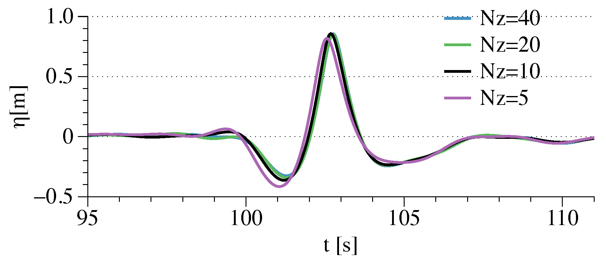
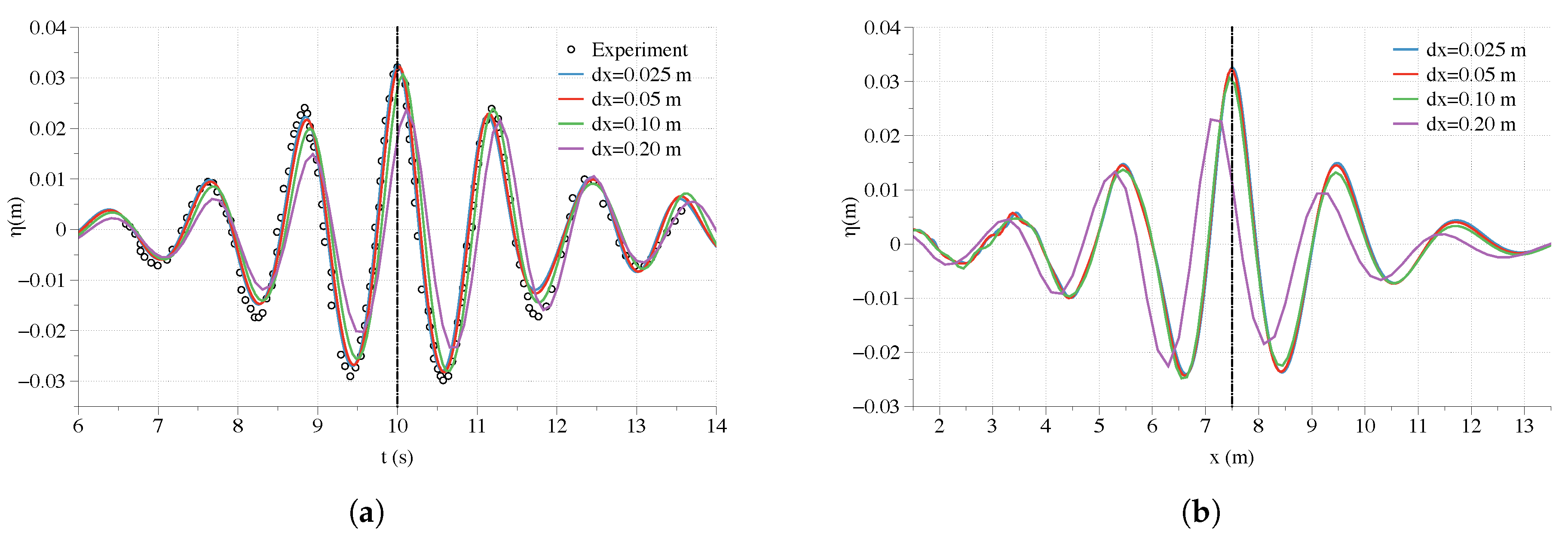
3.1. Validation of the Focused Wave Group Generation in the Numerical Wave Tank (NWT)

The focused irregular wave group is generated with the wave packet method and the numerical results are compared with the experimental data measured in the Large Wave Flume (GWK), Hannover, Germany [19]. The physical wave tank in the experiments is 300 m long with a constant water depth of h = 4.01 m . A piston-type wavemaker is used to generate the wave packet that focuses at the designated location at x F = 126.21 m and time at t F = 103 s . Following the experimental setup, a 2D numerical wave tank (NWT) 250 m long with a water depth of h = 4.01 m is used in the numerical test. A Neumann boundary is used at the inlet of the NWT to generate the wave packet that focuses at x F = 126.21 m and t F = 103 s . A 50 m long numerical beach is located at the outlet to absorb the wave energy. A linear wavemaker theory is used in the experiment [19], therefore a first-order focused wave theory is used in the numerical wave tank. The free surface elevations are measured at x = 3.59 m , 90.30 m and 126.21 m in both the physical and the numerical wave tank. The grid convergence study is shown in Figure 1. The time series at the focusing location and the wave profiles at the focusing time are nearly identical when a further grid refinement is made from d x = 0.25 m to d x = 0.167 m in the horizontal direction. Therefore, the grid size of d x = 0.25 m is considered sufficient for the simulation. A vertical grid convergence study with the σ -coordinate arrangement is also shown in Figure 2. With more than 10 cells, the focused wave shape, focusing time and focused wave crest height are nearly identical. It is therefore concluded that 10 cells in the water depth are sufficient to capture the extreme event accurately. Ning et al. [18] captured the focused wave shape in their NWT with only 16 frequency components due to the transient nature of the focusing event. In this study, the free surface time series with different numbers of frequency components are also compared in Figure 3. At the wave focusing event, 25 wave components appear to be sufficient to capture the focusing crest geometry very well as shown in Figure 3a. However, away from the crest, 50 components are needed to achieve convergence in the time domain. With a grid size of 0.25 m in the horizontal direction, 10 cells in the vertical direction and 50 wave components, a 180 s simulation takes 553 s on a Mac pro with with two Intel Xeon E5 processors (2.7 GHz). The simulated results are compared to the experimental observations in Figure 4. A favourable match is achieved at all wave probes. At the focusing point, the absolute difference between the simulated and measured wave peak height | H F ( s i m ) H F ( e x p ) | is divided by the measured wave peak height H F ( e x p ) to quantify the relative numerical error, which is found to be limited to 4.5 % .
The velocity potential, the vertical velocities at the focusing point and the grid are shown in Figure 5a,b. It is seen that the σ -grid follows the free surface well at the focusing peak with a sharp curvature. The velocity potential and the velocity field inside the water volume are also presented and the vertical velocity distribution for the intermediate water depth is demonstrated. The evolution of the wave packet and its vertical velocities are shown in Figure 6 for the sampled time frames t = 59.5 s , 103.0 s and 126.0 s . At t = 59.5 s , the wave packet propagates from the wave generating Neumann boundary with shorter waves leading the wave train and the trailing longer waves. At t = 103.0 s , all the wave components propagate to the focusing location at the same time, creating an amplified single peak with high velocities. At t = 126.0 s , the longer wave components surpass the shorter waves and the single peak decomposes into several smaller components of different frequencies.
In spite of the agreement between the experimental and numerical results, the asymmetry of the time series at the focusing location indicates that the real focusing event might not happen at the measured location in the experiment, i.e., not all the wave components superimpose simultaneously at the designated point. As can be observed in Figure 1a, both the simulated and physically measured focused wave at the designated focusing location at x = 126.21 m take place slightly ahead of the designated focusing time t = 103 s . In addition, at the designated focusing time, the waves in the numerical wave tank focus at x = 127.5 m , 1.29 m after the designated focusing location. These discrepancies indicate that there is a possibility that the real focusing event is delayed in comparison to the designated focusing location and time. Since it is challenging to perform a continuous measurement at very fine spatial intervals in the experiment, it is likely that there are no wave probes located at the real focusing point in the experiment. With the flexibility of the NWT, the spatial wave profiles along the longitudinal direction of the wave tank are plotted in one graph with a small interval of 0.06 s near t = 103.0 s as shown in Figure 7.
As can be seen from Figure 7, the highest peak appears at the location x = 129.38 m , reaching 0.8845 m , 8.5 % higher than the measured peak in the experiment. It indicates that the real focusing location is x = 129.38 m , 3.17 m after the designated focusing location, and the corresponding focus time is t = 103.4 s , 0.4 s after the designated focusing time. This finding is also illustrated in the time domain, as shown in Figure 8.
Previous research on focusing waves also found that the focusing time and location is delayed with increasing nonlinearity [79]. A detailed discussion on the influence of nonlinearity on the focusing wave group in time and space is presented in Section 3.2.
The input wave packet is a strictly defined wave train with a very specific spectrum. To investigate a more general wave focusing mechanism, the widely used NewWave theory [2,3] is also implemented in the proposed model. The numerical results are validated against the experiments performed by Ning et al. [18]. The experiments were conducted at the Dalian University of Technology in a wave flume 69 m long and 3 m wide. A constant water depth of 0.5 m is used during the tests. A 4 m region of foam is located at the outlet of the tank to reduce wave reflections. The experimental setup has been modified by [60] considering the computational convenience. The equivalence of the modified NWT to the original experimental setup has been demonstrated in [60]. The current study adopts the modified configuration of the NWT in a two-dimensional arrangement by removing the transverse dimension. Two of the physical tests are used for the validation in the study, the input wave conditions are summarized in Table 1. The Neumann boundary condition is used for the wave generation. The input wave in case NING 1 has a more linear behaviour, while the input wave in NING3 is expected to show more nonlinearity with higher steepness. As described by Ning et al. [18], a second-order wave theory is implemented in the wave generation to account for higher nonlinearity.
To begin with, the grid convergence studies in the x-direction are performed for both NING1 and NING3, which are shown in Figure 9 and Figure 10. Since the numerical wave tank length and the designated focusing location are modified from the original experiment, the experimental time series are shifted 0.6 s and 0.2 s respectively for the NING1 and NING3 cases to match the numerical focusing time in the numerical wave tank. These shifts are kept constant in all following comparisons. For both cases, further refinements of the horizontal grid from d x = 0.05 m to d x = 0.025 m do not improve the results further and the time series with both grid sizes match well with the experimental measurements. The location, time and crest height at focusing and the wave group shape adjacent to the focused crest are almost identical between the experimental and numerical results with the grid size of d x = 0.05 m . Consequently, the horizontal grid size of d x = 0.05 m is used in all the following simulations. In the vertical direction, the grid convergence study is shown in Figure 11. As can be seen in these two plots, the vertical grid resolution has a low influence on the accuracy of the model and a resolution of ten cells is found to be sufficient for both cases. As reported by Ning et al. [18], 20 frequency components are seen to be sufficient for all the tested wave conditions. To confirm this finding with the proposed model, the time series using different numbers of frequency components are compared at the focusing location in Figure 12. It is seen that 20 components are sufficient to capture the focusing wave group shape. All the following results are obtained with d x = 0.05 m in the horizontal plane, 10 cells in the vertical direction and 20 wave components for the irregular wave generation. The simulation time for the case NING1 is 20 s and it takes 37 s to finish the simulation with two Intel Xeon E5 processors (2.7 GHz) on a Mac Pro. On the same computer, the 32 s simulation for the case NING3 takes 76 s .
For the first case NING1, the wave focuses at nearly the exact designated focusing time at t = 10 s both in the experiment and the numerical simulation, as shown in Figure 9a. Correspondingly, the focusing location is found to be also nearly as designated at x = 7.5 m , as shown in Figure 9b. However, with a higher wave steepness and consequently stronger nonlinearity, both the focusing time and the focusing location are delayed for the case NING3. These observations are again confirmed by both the experiment and the simulations. In the case NING3, the wave group actually focuses at x = 8.475 m instead of focusing at x = 7.2 m , as designated. The numerical wave tank is able to provide a continuous output of the wave evolution at close time intervals. By plotting the wave profiles along the tank together at a time interval of 0.06 s near t = 10.7 s in Figure 13, one can clearly observe the real focusing location marked in red in comparison to the designated focusing location marked in blue. Similarly, the focusing time is delayed to t = 10.7 s rather than t = 10.0 s . The difference in the focusing location and time is mainly due to the nonlinear wave-wave interaction in the process of the wave group evolution. With stronger nonlinearity in NING3 case, the effect becomes more prominent. To demonstrate the evolution of the two different wave groups, the vertical velocity in the flow field for the two cases are illustrated in Figure 14. The focusing amplitude is much higher and the wave profile is much narrower with the steeper wave in NING3 in comparison to NING1. The difference in the focusing location is also visible when the two simulations are laid side by side. The vertical velocity magnitude of steeper waves is comparatively higher. This finding of the shifted focusing point due to nonlinear wave-wave interaction confirms the previous research reported by [6,18,55,79].

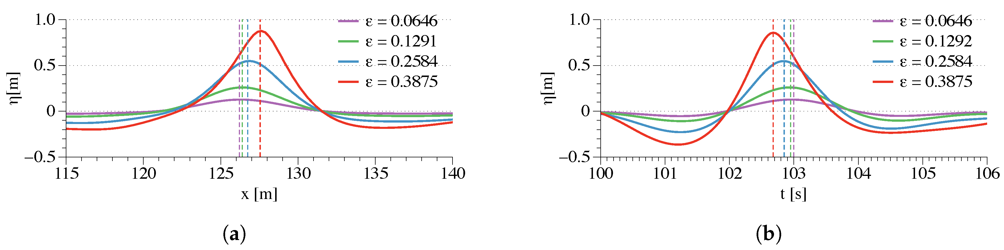
3.2. Effects of Nonlinearity

As found in the previous section, nonlinearity has a strong impact on the focused wave group evolution in time and space. In order to investigate the effect of wave nonlinearity, four wave groups with varying wave steepness are generated with the wave packet method, as shown in Table 2. The NWT configurations and designated focusing locations and times are the same as in the experiment shown in Section 3.1. The wave length L p is calculated based on linear wave theory with the corresponding peak period T p . The wave steepness is then defined as ϵ p = k p A F , where A F is the input value for the focusing amplitude, and k p = 2 π / L p is the corresponding wave number at the peak period.
The wave profiles in the longitudinal direction at the designated focusing time t = 103 s in the four cases are compared in Figure 15a. The time series at the designated focusing location x = 126.21 m in the four cases are compared in Figure 15b. As can be seen from the figure, stronger asymmetries are observed with steeper waves at the designated focusing time and location, indicating that the wave is not really focused at this location. As can be seen further in Figure 16a,b, the wave profiles and time series are more symmetric at their respective real focus locations and time. It is also seen that the focusing location and focusing time of the simulated waves approach the designed values for lower wave steepness. For example, the simulated focusing location and time are almost identical with the designed input at the wave steepness ϵ p = 0.0646 , as shown in Figure 17. The spatial and temporal differences at the designated focusing points are listed in Table 2. The relative differences in time and space are then defined as δ x F = Δ x F / L p and δ t F = Δ t F / L p . The general trend of increasing relative differences with increasing wave steepnesses is further demonstrated in Figure 18. The finding confirms the previous investigations and justifies the differences between the measured and real focusing point in the experiment of Clauss and Steinhagen [19].
Similarly, the influence of wave steepness on the focusing location and focusing time is also investigated with the NewWave theory. The designated input wave parameters are listed in Table 3. While keeping the same peak period, the focusing wave amplitude increases consistently. The time series at the respective focusing location and the wave profiles at the respective focusing time are plotted in Figure 19. It is seen that the differences between the real and designated focusing location and focusing time increase monotonically with increasing steepnesses. This finding agrees with the previous observations with the wave packet in the previous section. The absolute differences of focusing time and focusing location for each case are also listed in Table 3 and the relative differences are plotted in Figure 20. It is shown that there are almost no differences in the first two cases with lower steepnesses. As larger waves evolve, the focusing location and focusing time of the wave group shift downstream due to the highly nonlinear wave-wave interactions. After a certain threshold, the differences start to increase dramatically following a near-linear trend.

3.3. Effects of Frequency Bandwidth

Another factor influencing the properties of the focusing wave group is the frequency bandwidth. The combined effects of the nonlinearity and bandwidth (randomness) have been investigated previously by [80,81,82]. In this study, instead of focusing on the statistical properties, the authors focus on the geometrical properties and the general shape of the evolving wave train. Since the frequency range of a wave packet spectrum is strictly defined, the frequency bandwidth effects are only studied with the NewWave theory. Five different bandwidths are tested with the same peak frequency. The detailed specifications are listed in Table 4. The input wave height is the same as that defined in NING1. The focusing wave time series and wave profiles are plotted together in Figure 21. The focusing wave height decreases as the frequency bandwidth gets wider, the differences between the focusing wave height in comparison to the designated wave height are also listed in Table 4. It is seen that the focusing wave height decreases by 12 % with the widest bandwidth in case NB5. However, it is also noticed that the bandwidth does not have an influence on the focusing location and time.

3.4. Effects of Wave Generation Method

The presented waves are generated using a Neumann boundary when the gradient of the velocity potential changes are defined at the wave generation boundary. Another widely used wave generation method is the relaxation method [69]. Following the configurations in the experiments, a linear irregular wave theory and a second-order wave theory are used in the relaxation zones for the simulations using the wave packet method and the NewWave theory respectively. However, in both theories, only linear dispersion is represented inside the generation zone, which might result in errors in wave phases and the location and time of the focusing point. To demonstrate the difference between the two different wave generation methods, the validation cases presented in Section 3.1 are simulated with a relaxation wave generation zone and the results are compared to the corresponding results from the Neumann boundary condition. It is seen that the two wave generation methods show similar results for waves of relative weaker nonlinearity as in Figure 22 and Figure 23a. However, with increasing wave steepness and nonlinearity, the wave focusing properties are significantly different between the two wave generation methods, as shown in Figure 23b. The wave group generated by the relaxation method focuses earlier and overpredicts the focusing wave crest. In contrast, the waves groups generated with the Neumann method match the experiments very well.

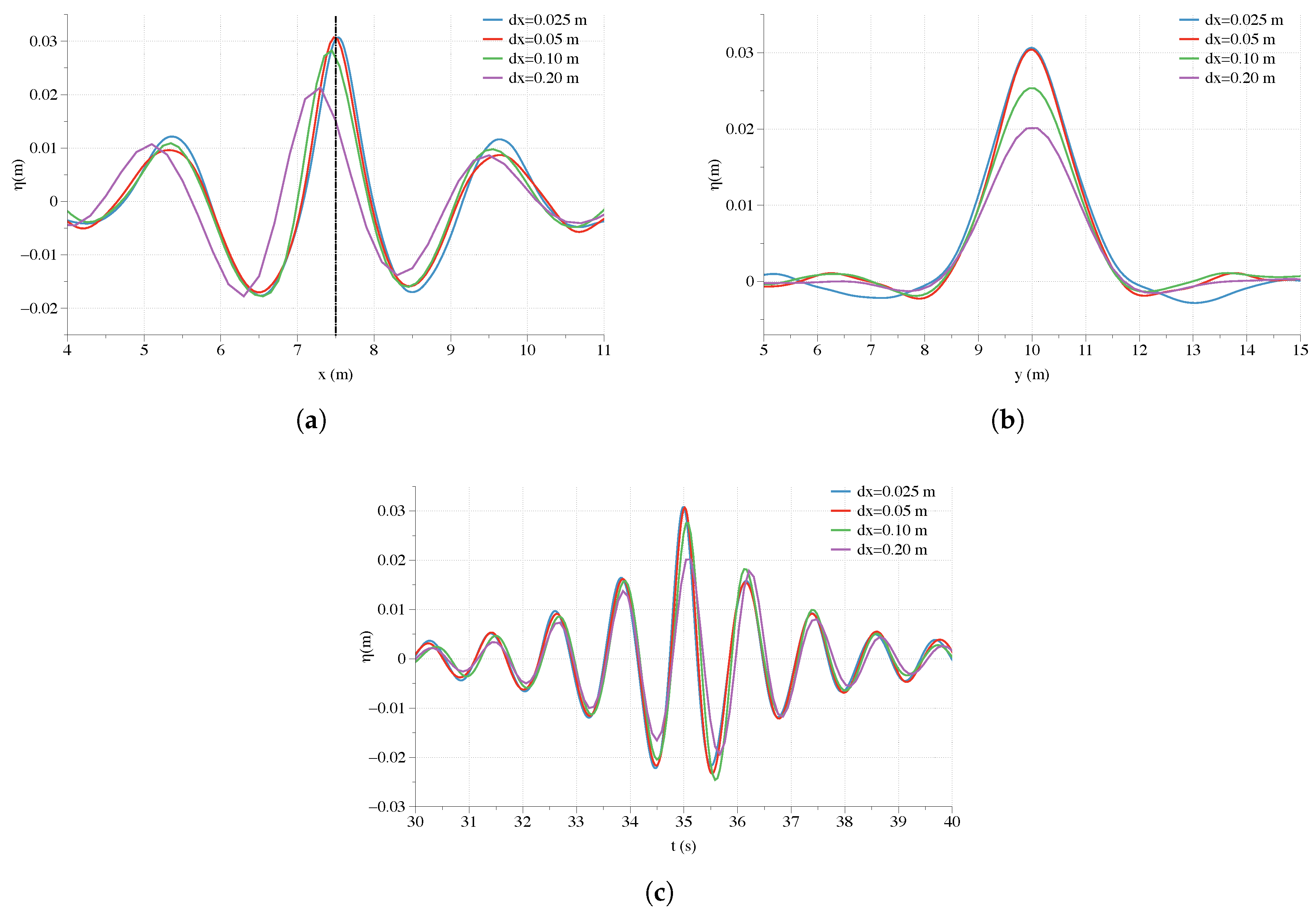
3.5. Effects of Directional Spreading on 3D Focused Wave Group

Rogue waves are more likely to happen in a crossing sea state [83]. To study the wave-wave interaction in a 3D sea-state, the JONSWAP spectrum and the PNJ directional spreading function are used to generate a multi-directional irregular wave field. The NewWave theory is used for wave focusing. A numerical wave basin 20 m long, 20 m wide with a constant water depth of 0.5 m is used in the study. Numerical beaches of 2 m width are arranged along the side walls and at the outlet of the tank. To fully resolve the 3D wave field, an Equal Energy method is used to discretise the frequency spectrum and spreading function. In this study, 500 frequency components and 20 directions are used, i.e., 10,000 wave components in total are generated at the boundary. The wave height and peak period in NING1 are used as the input wave properties in this simulation. The designated focusing location is ( x , y ) = ( 7.5 , 10 ) m and the focusing time is set to be 35 s . The wave profiles along the x-axis and the y-axis at the designated focusing time together with the free surface elevation time series are compared with different grid sizes in Figure 24. It is found that a grid size of 0.05 m is sufficient to achieve convergence. Ten cells are used in the vertical direction, resulting in 1.76 million cells in total. With 256 processors on NOTUR ’s supercomputer Fram, the 70 s simulation is finished in 5 h . The wave envelope is shown in Figure 25 by plotting the wave profile along the centre of the tank with a small time interval around t F = 35 s . It is seen that the highest peak of the wave envelope emerges at x = 7.5 m , indicating that the wave group focuses at the designated location. The evolution of the 3D focusing wave field is demonstrated in Figure 26 by showing the velocity magnitude in the wave field at the chosen time frames at t = 30 s , t = 35 s and t = 40 s . The 3D wave train forms several curved wave fronts asymmetric along the centreline of the tank and approaches the focusing point in a wedge-shape pattern in the x-y plane. At the focusing location, the wave profile along the x-axis is similar to the 2D NewWave profile as shown in Figure 24a and the wave profile along the y-axis is a single crested peak.
Different energy spreading conditions are investigated in the study with various values of the spreading parameter n, as shown in Equation (26). The wave profile along y = 10.0 m and x = 7.5 m are plotted in Figure 27 with different spreadings. A larger value of n signifies higher energy concentration and less spreading. It is seen from Figure 27a that the focused wave height slightly decreases with stronger energy spreading. The two secondary peaks adjacent to the focused peak also follow the same trend. The directional spreading function tends to redistribute the energy in the horizontal plane more evenly and leads to smaller waves near the focusing point. Figure 27a shows the wave profile in the y-direction at the focusing location. The focusing peak is higher and the wave profile is wider with more energy concentration. In contrast, with stronger directional spreading, the focused peak reduces and profile becomes narrower. The investigation indicates that different spreading conditions might lead to different load scenarios for marine structures due to varying peak height and the transverse dimension of the wavefront.

4. Conclusions

In this paper, an efficient fully-nonlinear potential flow model is introduced. The model solves the Laplace equation with a finite difference method on a σ -grid. The model employs high-order discretisation schemes in space and time which allows for larger grid sizes and time steps and ensures both the computational efficiency and accuracy. Ten vertical grids in the σ -coordinate system are usually found to be sufficient for surface wave applications. The focusing wave generated by the proposed model is validated against experiments using both the wave packet input and the NewWave theory. Favourable agreements are achieved with different wave conditions for both methods. The model is also used to create a 3D focusing wave group and the wave group focuses at the designated time and location. Further studies are performed to investigate the change of focusing location, focusing time, the geometry of the wave group and wave height in relation to the wave steepness, wave generation method, bandwidth and directional spreading. The focus of the study has been on the time domain analysis and geometry near the focusing point. The following findings are derived from the studies:
(1) Wave steepness and the nonlinearity affects the wave focusing location and time significantly. As a steeper wave group evolves, both the focusing location and the focusing time are shifted downstream due to stronger nonlinear wave-wave interactions.
(2) The close relation between the wave nonlinearity and the downstream shift of the focusing time and location challenges the physical test arrangement to allocate the wave probe at the exact focusing point. Instead of repeated attempts in a physical wave tank, a numerical wave model proves to be a useful tool to predict the exact real focusing time and location due to its flexibility and near-continuous output capacity.
(3) The frequency bandwidth does not have an influence on the focusing time and location but affects the focusing wave crest height. A wider bandwidth tends to reduce the focusing wave crest height.
(4) The focusing wave evolution is a very nonlinear phenomenon, the wave generation using a relaxation method does not represent the nonlinearity correctly as the wave steepness increases. Therefore, a Neumann boundary is recommended for the generation of the focusing wave group in an NWT.
(5) In a directional sea state, the directional spreading function also influences the 3D focused wave profile. In a more spreading sea, the focused wave crest height is reduced and the wave profile in the transversal plane becomes narrower.
In conclusion, the proposed FNPF model is efficient and flexible to investigate the focusing wave evolution comprehensively. The finding of the study offers insights into the numerical tank configurations for future studies on focused waves both numerically and experimentally.

Author Contributions

Conceptualization, W.W. and H.B.; methodology, W.W., C.P. and A.K.; software, H.B.; validation, W.W., A.K. and C.P.; formal analysis, W.W.; investigation, W.W.; resources, C.P.; data curation, A.K.; writing–original draft preparation, W.W.; writing–review and editing, W.W. and A.K.; visualization, W.W.; supervision, H.B.; project administration, H.B.; funding acquisition, H.B.

Funding

The research work has been funded by the Norwegian Public Roads Administration through the E39 fjord crossing project (No. 304624).

Acknowledgments

This study has been carried out as part of the E39 fjord crossing project (No. 304624) and the authors are grateful for the grants provided by the Norwegian Public Roads Administration. This study was also supported by the computational resources at the Norwegian University of Science and Technology (NTNU) provided by NOTUR, http://www.notur.no.

Conflicts of Interest

The authors declare no conflict of interest. The funders had no role in the design of the study; in the collection, analyses, or interpretation of data; in the writing of the manuscript, or in the decision to publish the results.

References

  1. Haver, S. A possible freak wave event measured at the Draupner jacket January 1 1995. In Proceedings of the Rogue Waves 2004, Brest, France, 20–22 October 2004. [Google Scholar]
  2. Lindgren, G. Some Properties of a Normal Process Near a Local Maximum. Ann. Math. Stat. 1970, 41, 1870–1883. [Google Scholar] [CrossRef]
  3. Tromans, P.S.; Anaturk, A.R.; Hagemeijer, P. A New Model for the Kinematics of Large Ocean Waves-Application as a Design Wave. Int. J. Offshore Polar. 1991, 4, 64–71. [Google Scholar]
  4. Jonathan, P.; Taylor, P.H. On Irregular, Nonlinear Waves in a Spread Sea. J. Offshore Mech. Arct. Eng. 1997, 119, 37–41. [Google Scholar] [CrossRef]
  5. Taylor, P.H.; Williams, B.A. Wave Statistics for Intermediate Depth Water—NewWaves and Symmetry. J. Offshore Mech. Arct. Eng. 2004, 126, 54–59. [Google Scholar] [CrossRef]
  6. Bateman, W.; Swan, C.; Taylor, P. On the Efficient Numerical Simulation of Directionally Spread Surface Water Waves. J. Comput. Phys. 2001, 174, 277–305. [Google Scholar] [CrossRef]
  7. Johannessen, T.B.; Swan, C. A Laboratory Study of the Focusing of Transient and Directionally Spread Surface Water Waves. Proceedings 2001, 457, 971–1006. [Google Scholar] [CrossRef]
  8. Borthwick, A.G.; Hunt, A.C.; Feng, T.; Taylor, P.H.; Stansby, P.K. Flow kinematics of focused wave groups on a plane beach in the U.K. Coastal Research Facility. Coast. Eng. 2006, 53, 1033–1044. [Google Scholar] [CrossRef]
  9. Whittaker, C.; Fitzgerald, C.; Raby, A.; Taylor, P.; Orszaghova, J.; Borthwick, A. Optimisation of focused wave group runup on a plane beach. Coast. Eng. 2017, 121, 44–55. [Google Scholar] [CrossRef]
  10. Hunt, A. Extreme Waves, Overtopping and Flooding at Sea Defences. Ph.D. Thesis, University of Oxford, Oxford, UK, 2003. [Google Scholar]
  11. Hunt-Raby, A.C.; Borthwick, A.G.; Stansby, P.K.; Taylor, P.H. Experimental measurement of focused wave group and solitary wave overtopping. J. Hydraul. Res. 2011, 49, 450–464. [Google Scholar] [CrossRef] [Green Version]
  12. Whittaker, C.; Raby, A.; Fitzgerald, C.; Taylor, P. The average shape of large waves in the coastal zone. Coast. Eng. 2016, 114, 253–264. [Google Scholar] [CrossRef] [Green Version]
  13. Whittaker, C.; Fitzgerald, C.; Raby, A.; Taylor, P.; Borthwick, A. Extreme coastal responses using focused wave groups: Overtopping and horizontal forces exerted on an inclined seawall. Coast. Eng. 2018, 140, 292–305. [Google Scholar] [CrossRef]
  14. Hofland, B.; Wenneker, I.; Van Steeg, P. Short test durations for wave overtopping experiments. In Proceedings of the 5th International Conference on the Application of Physical Modelling to Port and Coastal Protection, Varna, Bulgaria, 29 September–2 October 2014; pp. 349–358. [Google Scholar]
  15. Clauss, G.F.; Bergmann, J. Gaussian wave packets—A new approach to seakeeping testsof ocean structures. Appl. Ocean Res. 1986, 8, 190–206. [Google Scholar] [CrossRef]
  16. Clauss, G.F.; Kühhnlein, W.L. Numerical Simulation of Nonlinear Transient Waves and Its Validation by Laboratory Data. In Proceedings of the 3rd International Conference on Fast Sea Transport, Luebeck/Travemuende, Germany, 25–27 September 1995; Volume 2, pp. 1193–1204. [Google Scholar]
  17. Clauss, G.F.; Kuhnlein, W.L. A New Tool for Seakeeping Tests—Nonlinear Transient Wave Packets; 1997; Volume 2, pp. 269–285. Available online: https://www.osti.gov/etdeweb/biblio/634779 (accessed on 20 October 2019).
  18. Ning, D.Z.; Zang, J.; Liu, S.X.; Eatock Taylor, R.; Teng, B.; Taylor, P.H. Free-surface evolution and wave kinematics for nonlinear uni-directional focused wave groups. Ocean Eng. 2009, 36, 1226–1243. [Google Scholar] [CrossRef]
  19. Clauss, G.F.; Steinhagen, U. Numerical Simulation of Nonlinear Transient Waves and Its Validation by Laboratory Data. In Proceedings of the 9th International Offshore and Polar Engineering Conference, Brest, France, 30 May–4 June 1999. [Google Scholar]
  20. Sriram, V.; Schlurmann, T.; Schimmels, S. Focused wave evolution using linear and second order wavemaker theory. Appl. Ocean Res. 2015, 53, 279–296. [Google Scholar] [CrossRef]
  21. Bai, J.; Ma, N.; Gu, X. Numerical Simulation of Focused Wave and Its Uncertainty Analysis. J. Shanghai Jiaotong Univ. (Sci.) 2018, 23, 475–481. [Google Scholar] [CrossRef]
  22. Forristall, G.Z.; Barstow, S.F.; Krogstad, H.E.; Prevosto, M.; Taylor, P.H.; Tromans, P.S. Wave Crest Sensor Intercomparison Study: An Overview of WACSIS. J. Offshore Mech. Arct. Eng. 2004, 126, 26–34. [Google Scholar] [CrossRef]
  23. Buldakov, E.; Stagonas, D.; Simons, R. Extreme wave groups in a wave flume: Controlled generation and breaking onset. Coast. Eng. 2017, 128, 75–83. [Google Scholar] [CrossRef]
  24. Zang, J.; Taylor, P.H.; Tello, M. Steep Wave and Breaking Wave Impact on Offshore Wind Turbine Foundations—Ringing Re-Visited. In Proceedings of the 25th International Workshop on Water Waves and Floating Bodies, Harbin, China, 9–12 May 2010. [Google Scholar]
  25. Zang, J.; Gibson, R.; Taylor, P.; Eatock Taylor, R.; Swan, C. Second order wave diffraction around a fixed ship-shaped body in unidirectional steep waves. J. Offshore Mech. Arct. Eng. 2006, 128, 89–99. [Google Scholar] [CrossRef]
  26. Bai, W.; Taylor, R.E. Numerical simulation of fully nonlinear regular and focused wave diffraction around a vertical cylinder using domain decomposition. Appl. Ocean Res. 2007, 29, 55–71. [Google Scholar] [CrossRef]
  27. Grilli, S.T.; Guyenne, P.; Dias, F. A fully non-linear model for three-dimensional overturning waves over an arbitrary bottom. Int. J. Numer. Methods Fluids 2001, 35, 829–867. [Google Scholar] [CrossRef]
  28. Grilli, S.T.; Dias, F.; Guyenne, P.; Fochesato, C.; Enet, F. Progress in Fully Nonlinear Potential Flow Modeling of 3D Extreme Ocean Waves. In Advances in Numerical Simulation of Nonlinear Water Waves; World Scientific: Singapore, 2010; Chapter 1; pp. 75–128. [Google Scholar] [CrossRef]
  29. Brandini, C.; Grilli, S.T. Three-Dimensional Wave Focusing in Fully Nonlinear Wave Models. In Ocean Wave Measurement and Analysis (2001); American Society of Civil Engineers: Reston, VA, USA, 2001; pp. 1102–1111. [Google Scholar] [CrossRef]
  30. Fochesato, C.; Grilli, S.; Dias, F. Numerical modeling of extreme rogue waves generated by directional energy focusing. Wave Motion 2007, 44, 395–416. [Google Scholar] [CrossRef]
  31. Wu, G.; Taylor, R.E. Finite element analysis of two-dimensional non-linear transient water waves. Appl. Ocean Res. 1994, 16, 363–372. [Google Scholar] [CrossRef]
  32. Wu, G.; Taylor, R.E. Time stepping solutions of the two-dimensional nonlinear wave radiation problem. Ocean Eng. 1995, 22, 785–798. [Google Scholar] [CrossRef]
  33. Madsen, P.A.; Murray, R.; Sørensen, O.R. A new form of the Boussinesq equations with improved linear dispersion characteristics. Coast. Eng. 1991, 15, 371–388. [Google Scholar] [CrossRef]
  34. Nwogu, O. Alternative form of Boussinesq equations for nearshore wave propagation. J. Waterw. Port Coast. Ocean Eng. 1993, 119, 618–638. [Google Scholar] [CrossRef]
  35. Madsen, P.A.; Bingham, H.B.; Liu, H. A new Boussinesq method for fully nonlinear waves from shallow to deep water. J. Fluid Mech. 2002, 462, 1–30. [Google Scholar] [CrossRef]
  36. Chazel, F.; Benoit, M.; Ern, A.; Piperno, S. A double-layer Boussinesq-type model for highly nonlinear and dispersive waves. Proc. R. Soc. A 2009, 465, 2319–2346. [Google Scholar] [CrossRef]
  37. Bateman, W.; Swan, C.; Taylor, P. On the calculation of the water particle kinematics arising in a directionally spread wavefield. J. Comput. Phys. 2003, 186, 70–92. [Google Scholar] [CrossRef]
  38. Bateman, W.; Katsardi, V.; Swan, C. Extreme ocean waves. Part I. The practical application of fully nonlinear wave modelling. Appl. Ocean Res. 2012, 34, 209–224. [Google Scholar] [CrossRef]
  39. Craig, W.; Sulem, C. Numerical Simulation of Gravity Waves. J. Comput. Phys. 1993, 108, 73–83. [Google Scholar] [CrossRef]
  40. Ducrozet, G.; Bonnefoy, F.; Le Touzé, D.; Ferrant, P. A modified High-Order Spectral method for wavemaker modeling in a numerical wave tank. Eur. J. Mech. B/Fluids 2012, 34. [Google Scholar] [CrossRef]
  41. Bonnefoy, F.; Touzé, D.L.; Ferrant, P. A fully-spectral 3D time-domain model for second-order simulation of wavetank experiments. Part A: Formulation, implementation and numerical properties. Appl. Ocean Res. 2006, 28, 33–43. [Google Scholar] [CrossRef]
  42. Bonnefoy, F.; Touzé, D.L.; Ferrant, P. A fully-spectral 3D time-domain model for second-order simulation of wavetank experiments. Part B: Validation, calibration versus experiments and sample applications. Appl. Ocean Res. 2006, 28, 121–132. [Google Scholar] [CrossRef] [Green Version]
  43. Bingham, H.B.; Zhang, H. On the accuracy of finite-difference solutions for nonlinear water waves. J. Eng. Math. 2007, 58, 211–228. [Google Scholar] [CrossRef]
  44. Engsig-Karup, A.; Bingham, H. Boundary-fitted solutions for 3D nonlinear water wave-structure interaction. IWWWFB24. 2009; 20. [Google Scholar]
  45. Yates, M.L.; Benoit, M. Accuracy and efficiency of two numerical methods of solving the potential flow problem for highly nonlinear and dispersive water waves. Int. J. Numer. Methods Fluids 2015, 77, 616–640. [Google Scholar] [CrossRef]
  46. Raoult, C.; Benoit, M.; Yates, M.L. Validation of a fully nonlinear and dispersive wave model with laboratory non-breaking experiments. Coast. Eng. 2016, 114, 194–207. [Google Scholar] [CrossRef]
  47. Zhang, J.; Benoit, M.; Kimmoun, O.; Chabchoub, A.; Hsu, H.C. Statistics of Extreme Waves in Coastal Waters: Large Scale Experiments and Advanced Numerical Simulations. Fluids 2019, 4, 99. [Google Scholar] [CrossRef]
  48. Clamond, D.; Grue, J. A fast method for fully nonlinear water-wave computations. J. Fluid Mech. 2001, 447, 337–355. [Google Scholar] [CrossRef] [Green Version]
  49. Fructus, D.; Clamond, D.; Grue, J.; Øyvind, K. An efficient model for three-dimensional surface wave simulations: Part I: Free space problems. J. Comput. Phys. 2005, 205, 665–685. [Google Scholar] [CrossRef]
  50. Belibassakis, K.; Athanassoulis, G. A coupled-mode system with application to nonlinear water waves propagating in finite water depth and in variable bathymetry regions. Coast. Eng. 2011, 58, 337–350. [Google Scholar] [CrossRef]
  51. Athanassoulis, G.A.; Belibassakis, K.A.; Papoutsellis, C.E. An exact Hamiltonian coupled-mode system with application to extreme design waves over variable bathymetry. J. Ocean Eng. Mar. Energy 2017, 3, 373–383. [Google Scholar] [CrossRef]
  52. Engsig-Karup, A.P.; Eskilsson, C. Spectral Element FNPF Simulation of Focused Wave Groups Impacting a Fixed FPSO. In The 28th International Ocean and Polar Engineering Conference; International Society of Offshore and Polar Engineers: Sapporo, Japan, 2018; p. 8. [Google Scholar]
  53. Chen, L.F.; Zang, J.; Hillis, A.J.; Morgan, G.C.J.; Plummer, A.R. Numerical investigation of wave–structure interaction using OpenFOAM. Ocean Eng. 2014, 88, 91–109. [Google Scholar] [CrossRef]
  54. Vyzikas, T.; Stagonas, D.; Buldakov, E.; Greaves, D. The evolution of free and bound waves during dispersive focusing in a numerical and physical flume. Coast. Eng. 2018, 132, 95–109. [Google Scholar] [CrossRef]
  55. Westphalen, J.; Greaves, D.; Williams, C.; Hunt-Raby, A.; Zang, J. Focused waves and wave–structure interaction in a numerical wave tank. Ocean Eng. 2012, 45, 9–21. [Google Scholar] [CrossRef]
  56. Bihs, H.; Kamath, A.; Chella, M.A.; Aggarwal, A.; Arntsen, Ø.A. A new level set numerical wave tank with improved density interpolation for complex wave hydrodynamics. Comput. Fluids 2016, 140, 191–208. [Google Scholar] [CrossRef]
  57. Bihs, H.; Kamath, A.; Alagan Chella, M.; Arntsen, Ø. Extreme Wave Generation, Breaking and Impact Simulations With REEF3D. Proceeding of the 36th International Conference on Ocean, Offshore & Arctic Engineering, Trondheim, Norway, 25–30 June 2017. [Google Scholar]
  58. Bihs, H.; Kamath, A.; Alagan Chella, M.; Arntsen, Ø.A. Extreme Wave Generation, Breaking, and Impact Simulations Using Wave Packets in REEF3D. J. Offshore Mech. Arct. Eng. 2019, 141, 41802–41807. [Google Scholar] [CrossRef]
  59. Bihs, H.; Alagan Chella, M.; Kamath, A.; Arnsten, Ø.A. Wave-Structure Interaction of Focussed Waves with REEF3D. In Proceedings of the ASME 2016 35th International Conference on Ocean, Offshore and Arctic Engineering, Busan, Korea, 19–24 June 2016; number 49934. p. V002T08A027. [Google Scholar]
  60. Bihs, H.; Chella, M.A.; Kamath, A.; Arntsen, Ø.A. Numerical Investigation of Focused Waves and Their Interaction With a Vertical Cylinder Using REEF3D. J. Offshore Mech. Arct. Eng. 2017, 139, 41101–41108. [Google Scholar] [CrossRef]
  61. Paulsen, B.T.; Bredmose, H.; Bingham, H. An efficient domain decomposition strategy for wave loads on surface piercing circular cylinders. Coast. Eng. 2014, 86, 57–76. [Google Scholar] [CrossRef]
  62. Chella, M.A.; Bihs, H.; Myrhaug, D. Wave impact pressure and kinematics due to breaking wave impingement on a monopile. J. Fluids Struct. 2019, 86, 94–123. [Google Scholar] [CrossRef]
  63. Kamath, A.; Chella, M.A.; Bihs, H.; Arntsen, Ø.A. Evaluating wave forces on groups of three and nine cylinders using a 3D numerical wave tank. Eng. Appl. Comput. Fluid Mech. 2015, 9, 343–354. [Google Scholar] [CrossRef]
  64. Kamath, A.; Bihs, H.; Arntsen, Ø.A. Study of Water Impact and Entry of a Free Falling Wedge Using Computational Fluid Dynamics Simulations. J. Offshore Mech. Arct. Eng. 2017, 139, 31802–31806. [Google Scholar] [CrossRef]
  65. Ahmad, N.; Bihs, H.; Myrhaug, D.; Kamath, A.; Arntsen, Ø.A. Numerical modelling of pipeline scour under the combined action of waves and current with free-surface capturing. Coast. Eng. 2019, 148, 19–35. [Google Scholar] [CrossRef]
  66. Bihs, H.; Kamath, A.; Aggarwal, A.; Pakozdi, C. Efficient Wave Modeling using Nonhydrostatic Pressure Distribution and Free Surface Tracking on Fixed Grids. J. Offshore Mech. Arct. Eng. 2019, 141, 41805–41806. [Google Scholar] [CrossRef]
  67. Beji, S.; Battjes, J.A. Experimental investigation of wave propagation over a bar. Coast. Eng. 1993, 19, 151–162. [Google Scholar] [CrossRef]
  68. Bihs, H.; Wang, W.; Martin, T.; Kamath, A. REEF3D::FNP—A Flexible Fully Nonlinear Potential Flow Solver. In Proceeding of the 38th International Conference on Ocean, Offshore & Arctic Engineering, Glasgow, Scotland, UK, 9–14 June 2019. in press. [Google Scholar]
  69. Mayer, S.; Garapon, A.; Sørensen, L.S. A fractional step method for unsteady free surface flow with applications to non-linear wave dynamics. Int. J. Numer. Methods Fluids 1998, 28, 293–315. [Google Scholar] [CrossRef]
  70. Van der Vorst, H. BiCGStab: A fast and smoothly converging variant of Bi-CG for the solution of nonsymmetric linear systems. SIAM J. Sci. Comput. 1992, 13, 631–644. [Google Scholar] [CrossRef]
  71. Jiang, G.S.; Shu, C.W. Efficient Implementation of Weighted ENO Schemes. J. Comput. Phys. 1996, 126, 202–228. [Google Scholar] [CrossRef] [Green Version]
  72. Shu, C.W.; Osher, S. Efficient Implementation of Essentially Non-Oscillatory Shock Capturing Schemes. J. Comput. Phys. 1988, 77, 439–471. [Google Scholar] [CrossRef]
  73. Hennig, J. Generation and Analysis of Harsh Wave Environments. Ph.D. Thesis, Technical University Berlin, Berlin, Germany, 2005. [Google Scholar]
  74. DNV Recommended Practice RP-C205 “Environmental Conditions and Environmental Loads”; Technical Report; 2000; Available online: https://books.google.com.ph/books?hl=en&lr=&id=p6dpDQAAQBAJ&oi=fnd&pg=PR5&dq=In+Advances+in+Numerical+Simulation+of+Nonlinear+Water+Waves%3B+World+Scientific:&ots=ACLl5FYHQ0&sig=GJHXXMCd29gQ23p3FTAQD1jHnZk&redir_esc=y#v=onepage&q=In%20Advances%20in%20Numerical%20Simulation%20of%20Nonlinear%20Water%20Waves%3B%20World%20Scientific%3A&f=false (accessed on 20 October 2019).
  75. Pierson, W.J.; Neumann, G.; James, R.W. Practical Methods for Observing and Forecasting Ocean Waves by Means of Wave Spectra and Statistics; U.S. Government Printing Office: Washington, DC, USA, 1955.
  76. Duarte, T.; Gueydon, S.; Jonkman, J.; Sarmento, A. Computation of Wave Loads under Multidirectional Sea States for Floating Offshore Wind Turbines. In Proceedings of the 33rd International Conference on Ocean, Offshore and Arctic Engineering, San Francisco, CA, USA, 8–13 June 2014. [Google Scholar] [CrossRef]
  77. Jefferys, E.R. Directional seas should be ergodic. Appl. Ocean Res. 1987. [Google Scholar] [CrossRef]
  78. Schäffer, H.A. Second-Order Wavemaker Theory for Irregular Waves. Ocean Eng. 1996, 23, 47–88. [Google Scholar] [CrossRef]
  79. Baldock, T.E.; Swan, C.; Taylor, P.H. A laboratory study of nonlinear surface waves on water. Philos. Trans. R. Soc. A 1996. [Google Scholar] [CrossRef]
  80. Alber, I.E.; Stewartson, K. The effects of randomness on the stability of two-dimensional surface wavetrains. Proc. R. Soc. Lond. A 1978, 363, 525–546. [Google Scholar] [CrossRef]
  81. Socquet-Juglard, H.; Dysthe, K.; Trulsen, K.; Krogstad, H.E.; Liu, J. Probability distributions of surface gravity waves during spectral changes. J. Fluid Mech. 2005, 542, 195–216. [Google Scholar] [CrossRef] [Green Version]
  82. Dysthe, K.B.; Trulsen, K.; Krogstad, H.E.; Socquet-Juglard, H. Evolution of a narrow-band spectrum of random surface gravity waves. J. Fluid Mech. 2003, 478, 1–10. [Google Scholar] [CrossRef] [Green Version]
  83. Kharif, C.; Pelinovsky, E.; Slunyaev, A. Rogue Waves in the Ocean. In Advances in Geophysical and Environmental Mechanics and Mathematics; Springer: Berlin/Heidelberg, Germany, 2009. [Google Scholar] [CrossRef]
Figure 1. Grid convergence study of the focusing wave group generated using a wave packet method. (a) Comparison of time series at the designated focusing location with different grid sizes. The time series are also compared to the measurements. (b) Comparison of wave profiles at the designated focusing time with different grid sizes. Four grid sizes are investigated: d x = 0.167 m , 0.25 m , 0.5 m and 1.0 m . 10 vertical cells are used in the study.
Jmse 07 00375 g001
Figure 2. The grid convergence study of the vertical grid resolution in a σ -coordinate arrangement for the focusing wave group generated using a wave packet method.
Jmse 07 00375 g002
Figure 3. Convergence study for the number of frequency components for the generation of the focused wave group using the wave packet approach, (a) time series near the focusing event with a different number of frequency components, (b) time series away from the focusing event with a different number of frequency components.
Jmse 07 00375 g003
Figure 4. Comparison of the wave elevation time series at the three wave probes between the numerical wave tank and the experiment for the wave packet study. (d.) The close-up view of the wave profile near the focusing region.
Jmse 07 00375 g004
Figure 5. Flow information and σ -grid near the focusing event, (a) velocity potential in the water volume, (b) the vertical velocity component in the water volume.
Jmse 07 00375 g005
Figure 6. Vertical velocity component during the evolution of the focused wave group generated by the wave packet method, (a) t = 59.5 s , (b) t = 103.0 s , (c) t = 126.0 s .
Jmse 07 00375 g006
Figure 7. Wave profiles along the longitudinal direction of the wave tank are plotted in one graph at an interval of 0.06 s near t = 103.0 s . The red dash-dot line indicates the real focusing location in the NWT at x = 129.38 m . The blue dash-dot line indicates the designated focusing location at x = 126.21 m .
Jmse 07 00375 g007
Figure 8. The comparison of the time series at the designated focusing location at x = 126.21 m and at the real focusing location at x = 129.38 m as detected in the numerical simulation. The black dash-dot curve is the time series measured in the experiment at x = 126.21 m and the vertical black dash-dot line indicates the measured focusing time at t = 102.825 s . The red solid curve is the time series at x = 126.21 m in the numerical wave tank (NWT), and the vertical red dashed line indicates the corresponding numerical focusing time t = 102.7 s . The red dash-dot curve is time series at the real focusing location x = 129.38 m in the NWT and the vertical red dash-dot line indicates the real focusing time t = 103.4 s . The vertical black dashed line is the designated focusing time at t = 103 s .
Jmse 07 00375 g008
Figure 9. Grid convergence study in the x-direction for the case NING1, where four grid sizes are tested d x = 0.025 , 0.05 , 0.1 and 0.2 m . Ten vertical cells are used in the study. (a) The time series at the focusing location x = 7.5 m , (b) the spatial wave profiles at the focusing time t = 10.0 s .
Jmse 07 00375 g009
Figure 10. Grid convergence study in the x-direction for the case NING3, where four grid sizes are tested d x = 0.025 , 0.05 , 0.1 and 0.2 m . Ten vertical cells are used in the study. (a) The time series at the focusing location x = 8.475 m , (b) the spatial wave profiles at the focusing location t = 10.7 s .
Jmse 07 00375 g010
Figure 11. Grid convergence study in the z-direction, (a) the time series at the focusing location x = 7.5 m for case NING1, (b) the time series at the focusing location x = 8.475 m for case NING3. The tested numbers of grid in the vertical direction are N z = 5 , 10 , 20 and 40 .
Jmse 07 00375 g011
Figure 12. Convergence study of the number of frequency components, (a) the time series at the focusing location x = 7.5 m for case NING1, (b) the time series at the focusing location x = 8.475 m for case NING3. The tested numbers of frequency components are N = 10 , 15 , 20 , 100 and 500 .
Jmse 07 00375 g012
Figure 13. The wave profiles along the longitudinal direction of the wave tank are plotted in one graph at an interval of 0.06 s near t = 10.7 s for the simulation case NING3. The red dash-dot line indicates the real focusing location in the NWT at x = 8.475 m . The blue dash-dot line indicates the designated focusing location at x = 7.2 m . The red curve is the wave profile at the real focusing time.
Jmse 07 00375 g013
Figure 14. The vertical velocity in the wave fields at the focusing time, (a) for the simulation case NING1 with a less steep input wave, (b) for the simulation case NING3 with a more steep input wave. The black vertical dashed line in (a) indicates the location of the focused wave crest in the case NING1, and the red vertical dashed line in (b) indicates the location of the focused wave crest in the case NING3. The black dashed line in (a) is extended to (b), and the red dashed line in (b) is extended to (a) so that the horizontal distance between the focused wave crests in the two cases is straightforwardly observable.
Jmse 07 00375 g014
Figure 15. Comparison of the wave surface elevations at the designated focusing time and location with four different wave steepnesses, (a) the wave profiles in the longitudinal direction at t = 103 s , (b) the time series at x = 126.21 m .
Jmse 07 00375 g015
Figure 16. Comparison of the wave surface elevations at the respective real focusing time and location with four different wave steepnesses, (a) the wave profiles in the longitudinal direction, (b) the time series at the respective real focusing location.
Jmse 07 00375 g016
Figure 17. The wave profiles along the longitudinal direction of the wave tank with the wave steepness ϵ p = 0.0646 are plotted in one graph at an interval of 0.06 s near t = 103.0 s . The red dash-dot line indicates the real focusing location in the NWT at x = 126.21 m , which aligns with the designated focusing locations.
Jmse 07 00375 g017
Figure 18. The relative spatial differences in focusing location δ x F and temporal differences in focusing time δ t F in relation to wave steepness in the simulation with the wave packet.
Jmse 07 00375 g018
Figure 19. Comparison of wave surface elevations at the respective real focusing time and location with four different wave steepnesses (a) the time series at respective real focusing time, (b) the comparison of the wave profiles in the longitudinal direction at the respective real focusing locations.
Jmse 07 00375 g019
Figure 20. The relative spatial differences in focusing location δ x F and temporal differences in focusing time δ t F in relation to wave steepness in the simulation with the NewWave theory.
Jmse 07 00375 g020
Figure 21. Comparison of the wave surface elevations with five different frequency bandwidths. (a) the time series at the designated focusing location x = 7.5 m , (b) the spatial wave profile in the longitudinal direction at the designated focusing time t = 10 s .
Jmse 07 00375 g021
Figure 22. Comparison of the time series at the focusing location of 126.21 m generated by a relaxation method and a Neumann boundary using the wave packet input.
Jmse 07 00375 g022
Figure 23. Comparison of the time series at the focusing location of 7.5 m generated by a relaxation method and a Neumann boundary, (a) for the simulation case NING1, (b) for the simulation case NING3.
Jmse 07 00375 g023
Figure 24. Grid convergence study for the 3D wave focusing simulation with four grid sizes d x = 0.025 , 0.05 , 0.1 and 0.2 m , 10 vertical cells are used in the study. (a) Wave profile along the x-axis at y = 10 m and t F = 35 s , (b) wave profile along the y-axis at x = 7.5 m and t F = 35 s , (c) free surface elevation time series at ( x , y ) = ( 7.5 , 10 ) m .
Jmse 07 00375 g024
Figure 25. Wave profile envelop along the x-axis at y = 10 m , plotted with short time intervals around t F = 35 s .
Jmse 07 00375 g025
Figure 26. Velocity magnitude in the 3D focusing wave field. The time frames are t = 30 s , t = 35 s and t = 40 s from left to right.
Jmse 07 00375 g026
Figure 27. Comparison of the wave free surface elevations with four different spreading functions, (a) comparison of the wave profiles in the longitudinal x-z plane at y = 10 m , (b) comparison of wave profiles in the transverse y-z plane at x = 7.5 m .
Jmse 07 00375 g027
Table 1. The focusing wave inputs and the real focusing properties for the validation cases.
Case No. T p (s) A F (m) x F (m) t F (s) x Fr (m) t Fr (s)
NING11.200.03137.510.07.510.0
NING31.250.08757.210.08.47510.7
Table 2. The wave inputs and the absolute differences in the focusing points for the wave groups generated using the wave packet with different wave steepnesses.
Case No. A F (m) T p (s) L p (m) ϵ p x F (m) t F (s)
Case PK10.254.2024.320.06460.000.00
Case PK20.504.2024.320.12920.090.05
Case PK31.004.2024.320.25840.540.15
Case PK41.504.2024.320.38751.290.31
Table 3. The wave inputs and the absolute differences in the focusing points for the wave groups generated using the NewWave theory with different wave steepnesses.
Case No. A F (m) T p (s) L p (m) ϵ p x F (m) t F (s)
NS10.03911.202.000.12290.0000.000
NS20.04701.202.000.14750.0750.015
NS30.06261.202.000.19670.3750.165
NS40.07831.202.000.24581.0250.520
Table 4. The input wave properties with different bandwidth for the wave spectrum.
Case No. ω Range (rad/s)Bandwidth (rad/s) H F (m) δ H F ( % )
NB1[5.02, 6.54]1.520.061911.10
NB2[4.27, 7.04]2.770.061421.88
NB3[3.77, 7.54]3.770.061431.87
NB4[2.77, 9.54]6.770.056909.11
NB5[1.77, 11.04]9.270.0549512.22

