Article

Elastoplastic Solution of Cylindrical Cavity Expansion in Unsaturated Offshore Island Soil Considering Anisotropy

1
Department of Civil Engineering, University of Shanghai for Science and Technology, Shanghai 200093, China
2
Department of Geotechnical Engineering, Tongji University, Shanghai 200092, China
3
Department of Structural Engineering, University of California San Diego, San Diego, CA 92093-0085, USA
*
Author to whom correspondence should be addressed.
J. Mar. Sci. Eng. 2024, 12(2), 308; https://doi.org/10.3390/jmse12020308
Submission received: 26 December 2023 / Revised: 1 February 2024 / Accepted: 5 February 2024 / Published: 9 February 2024

Abstract

:
An elastoplastic analysis scheme for the cylindrical cavity expansion in offshore islands unsaturated soils considering anisotropy is established. The hydraulic properties and anisotropy caused by stress of unsaturated soils are coupled in an elastoplastic constitutive matrix for unsaturated soil to obtain the governing equations for the cylindrical cavity expansion problem, with an analytical solution that utilizes the original hydro-mechanical state of the soil as the initial conditions. Through a comparative analysis with other analytical solutions, the effectiveness of the new solution is verified. Moreover, the swelling response of the cylindrical cavity expansion in unsaturated soils is examined by systematically analyzing different parameters of the surrounding soil. The findings reveal that the development and rate of anisotropy in normal consolidated soil and over-consolidated soil exert a significant impact on the soil’s mechanical characteristics. Nevertheless, the alteration in the model constant h has little effect on the soil’s mechanical characteristics. The analytical solution introduces anisotropy and broadens the expansion theory of unsaturated soils to yield a more comprehensive theoretical framework for the comprehensive analysis of offshore islands’ unsaturated soils.

1. Introduction

The expansion or contraction of a cavity in geotechnical media represents a fundamental one-dimensional problem [1,2,3]. Addressing this necessitates a fusion of continuum media mechanics principles and fundamental mathematical models capable of delineating intrinsic geotechnical media relationships [4,5,6].
Presently, geotechnical intrinsic theories primarily lean on elasticity and plasticity theories, serving as the cornerstone [7,8,9,10,11]. Although initial solutions for the cylindrical cavity expansion relied on ideal elastic–plastic assumptions, recent decades have witnessed an evolution towards critical state models within the theory of cylindrical cavity expansion [12,13,14]. Collins et al. [15] pioneered the integration of critical state soil model into the theory of cylindrical cavity expansion, followed by Zhou et al. [16], who refined it by adopting a more innovative critical state model to deduce the cylindrical cavity expansion. In the recent interim, Chen and Abousleiman [17,18] proposed a standard analytical framework for analyzing cavity expansion issues in soils at the critical state based on the Lagrangian description. Since then, different advanced soil models have been gradually introduced into the theory of cavity expansion to address challenges in various field conditions. These models include the anisotropic modified Cam-Clay model [19,20], the boundary surface model [21,22,23,24], the cutting-edge anisotropic critical state clay plasticity model [25], and the unified condition matrix for clay and sand [26].
Under natural or artificial changes in the environment, soil in offshore islands often undergoes dehumidification, humidification, and alternation of dry and wet processes. At this point, soil will exhibit characteristics such as volume, strength, permeability, and consolidation that markedly differ from those in its saturated condition. The strength of unsaturated soil plays a pivotal role in the analysis of the pile-bearing capacity of wind farms in offshore islands [27,28,29]. Sun et al. [29] proposed the unsaturated soil critical state model (UCSM) and introduced the SWCC (soil–water characteristic curve, which is a curve describing the relationship between the water content in soil and the soil water potential) related to the void ratio to propose the exact solution of the reaming problem under different drainage conditions, respectively. They expanded the theory of cavity expansion to encompass more general unsaturated soils by employing a coupled hydraulic-mechanical critical state model in their solution approach. However, the solution proposed by Chen et al. [30] does not take into account the anisotropy of the soil. In fact, anisotropy, which signifies variations in properties based on direction and results in distinct attributes along different axes (distinct from non-uniformity), is widespread in geomaterials and geotechnical engineering projects [31,32]. Dafalias [33] once proposed an evolution law of anisotropic variables using the rotated and twisted ellipse in the p q flat as the yield surface, which has been widely adopted and validated by subsequent researchers. Therefore, in this paper, the anisotropic framework presented by Dafalias [34] is further integrated with the elastoplastic analytical solution proposed by Chen et al. [30], aiming to improve the elastoplastic analytical solution of the cylindrical cavity expansion problem in unsaturated anisotropic soil. Furthermore, for the purpose of adequately representing the evolution of anisotropic variables, two new model constants, denoted as x and h , are introduced, where x regulates the extent of anisotropy that might emerge during consistent loading and h governs the rate at which such anisotropy develops or disappears. Through these enhancements, this study successfully broadens the scope of the cylindrical cavity expansion problem in unsaturated soils from an isotropic to an anisotropic context.

2. Basic Analysis Model

Figure 1 illustrates the expansion process of the cylindrical cavity resulting from the initial horizontal σ h 0 and vertical total pressure σ v 0 . As the inside total stress of the cavity increases from σ h 0 to σ a , the initial radius a 0 is expanded accordingly to present radius a . Any soil material particles within a certain range of the cavity perimeter move from r 0 to the present location r over the course of this interval. With the rise in interior stress, the soil particles surrounding the cavity yield and create a plastic region. The plastic deformation happens in the region a r r p , where r p indicates the position of the soil material particles at the present elastoplastic border (EPB) with the initial position r p 0 . Soils other than EPB exhibit elastic behavior.
The balanced equation of soil material particles during the expansion process were denoted by Chen et al. [30] as follows:
D σ r D r S r D s D r s D S r D r + σ r σ θ r = 0

3. The Establishment of an Anisotropic Elastoplastic Model

3.1. Stress and Strain Variables

Unsaturated soil contains both liquid and atmosphere within its pores; this is the cause of suction, which involves the coupling of the interaction between hydraulic behavior and soil mechanical behavior. Therefore, this paper proposes to use the average soil skeleton pressure tensor σ i j and strain tensor ε ij to describe the mechanical behavior, and the corresponding hydraulic behavior is expressed by suction s and saturation Sr. The above variables can be described according to the definition of Sun et al. [34] as
σ i j = σ i j S r u w + 1 S r u a δ i j
s = u a u w
where σ i j is the overall pressure tensor; S r is the saturation; u a and u w denote the pore–air and pore–water pressures, respectively; and δ i j is the Kronecker delta.
It should be noted that because the hydraulic variables and suction have been incorporated into the average skeleton stress expression, the hydromechanical behavior of unsaturated soils could be replicated.

3.2. Soil–Water Characteristic Behavior

For the purpose of combining hydraulic and mechanical characteristics, the specific volume v can be incorporated into the major arid curve and major moist curve in the SWCC. For this paper, a widely used SWCC curve put forward by Sun et al. [29] was adopted, which is uniformly expressed as
d S r = λ se d v β d s s
When β = κ sr , it is on the scanning curve, and when β = λ sr , the hydraulic behavior is on the primary desiccation–wet curve.

3.3. LC Yield Function

In order to describe the conditions under which soil transitions from an elastic condition to a plastic condition, the yield function curve of anisotropic unsaturated soil is given as shown in Figure 2. Assuming that the soil obeys the relevant flow laws, it takes the following form:
f LC = p 2 p p y + 3 2 M 2 s i j p α i j s i j p α i j + p y p p α i j α i j = 0
α ˙ i j = Λ α ¯ i j = Λ 1 + e λ s κ tr f p h p y s i j x p α i j
In the formula, p ( = σ i j σ i j / 3 ) is the average effective pressure; M is the pressure ratio at critical state; d ε i j p is the plastic strain increment tensor caused by loading; Λ is the plastic scalar multiplier and its detailed derivation is shown in Appendix A; s i j ( = σ i j δ i j p ) is the deviatoric pressure tensor; are Macaulay brackets; t r represents the trace function; κ is the slope of the unsaturated soil loal–uninstall line in the e ln p flat; and e is the void ratio. In the unsaturated soil model, we assumed that it remains approximately unchanged within the range of suction variation; x and h are two model constants that control the degree of anisotropy, which can evolve separately under the constant load and anisotropic development rate; and p y represents the yield stress of unsaturated soil under suctio s , expressed by the following equation p 0 y :
p y = p n p 0 y p n λ 0 κ λ s κ
In the following formula, λ 0 and λ s represent the slope of the standard compression line of saturated and unsaturated soil (matric suction is s ) on the e ln p flat, respectively, where λ s can be represented by λ 0 (Alonso et al. [11]):
λ s = λ 0 1 b e c s + b
Based on Formulas (5) and (6) and related flow rules, d ε i j p can be expressed by the following formula:
d ε i j p = Λ f LC σ i j

4. Elastic Zone Response

From the above balanced equations and linear elasticity theory, the following stress distribution can be obtained [17]:
σ r = σ h 0 + σ rp σ h 0 r p r 2
σ θ = σ h 0 σ rp σ h 0 r p r 2
σ v = σ v 0
U r = 1 + μ σ rp σ h 0 E r p 2 r
where σ rp will present specific expressions later in the article.

5. Elastoplastic Analysis

The strain increment is easily obtained
D ε r = D ε r e + D ε r p
D ε θ = D ε θ e + D ε θ p
D ε z = D ε z e + D ε z p
where D ε r e , D ε θ e , and D ε z e represent elastic strain increments; and D ε r p , D ε θ p , and D ε z p are the three principle plastic strain increments.
D ε i j = Λ f p p σ i j + f s m n s m n σ i j = Λ f p δ i j 3 + f s m n s m n σ i j = Λ f p δ i j 3 + f s i j
The expression for three primary plastic strain increments can be derived in accordance with the pertinent liquidity regulation outlined in Equations (5) and (9). This is denoted as
D ε r p = A A r A r D σ r + A θ D σ θ + A z D σ z + A s D s
D ε θ p = A A θ A r D σ r + A θ D σ θ + A z D σ z + A s D s
D ε z p = A A z A r D σ r + A θ D σ θ + A z D σ z + A s D s
where
A = 1 K p = 1 v λ 0 κ p 0 y p 3 α i j α i j 2 M 2 1 f p p y p 0 y + 3 p M 2 v λ s κ f p c p y p y α i j s i j s i j x p α i j
A r = 1 3 f p + f s r = 1 3 2 p p y + 3 2 M 2 p y α i j α i j 2 α i j s i j + 3 M 2 s r p α r
A θ = 1 3 f p + f s θ = 1 3 2 p p y + 3 2 M 2 p y α i j α i j 2 α i j s i j + 3 M 2 s θ p α θ
A z = 1 3 f p + f s z = 1 3 2 p p y + 3 2 M 2 p y α i j α i j 2 α i j s i j + 3 M 2 s z p α z
A s = f p y p y s = p 3 α i j α i j 2 M 2 1 λ 0 λ 0 κ p y c 1 b e c s λ s κ 2 ln p 0 y p n
Λ = 1 K b A r D σ r D r + A θ D σ θ D r + A z D σ z D r + A s D s D r
D α r D r = 1 K p A r D σ r D r + A θ D σ θ D r + A z D σ z D r + A s D s D r v λ s κ f p c p y s r x p α r
D α θ D r = 1 K p A r D σ r D r + A θ D σ θ D r + A z D σ z D r + A s D s D r v λ s κ f p c p y s θ x p α θ
D α z D r = 1 K p A r D σ r D r + A θ D σ θ D r + A z D σ z D r + A s D s D r v λ s κ f p c p y s z x p α z
From Equations (5) and (7), p 0 y can be represented by p n as
p 0 y = p n 1 p n p 2 + 3 2 M 2 s i j p α i j s i j p α i j p 2 α i j α i j p 3 2 M 2 p α i j α i j λ s κ λ 0 κ
Substituting Equations (4), (15), and (16a–c) into Equation (14a–c), the elastic–plastic constitutive relationship of this problem may be depicted in the subsequent matrix arrangement:
D σ r D σ θ D σ z D s = B 11 / Δ B 12 / Δ B 13 / Δ B 14 / Δ 1 B 21 / Δ B 22 / Δ B 23 / Δ B 24 / Δ 1 B 31 / Δ B 32 / Δ B 33 / Δ B 34 / Δ 1 0 0 0 B 44 D ε r D ε θ D ε z D S r + λ se D v
where B i j , Δ , and Δ 1 can be represented by a trio of primary stresses σ r , σ θ , σ z , v , and s , that is, their explicit functions.
B 11 = E A E ( A θ 2 + A z 2 + 2 μ A θ A z ) + ( 1 μ 2 )
B 12 = B 21 = E E A ( μ A z 2 A r A θ μ A r A z μ A θ A z ) + μ ( 1 + μ )
B 13 = B 31 = E E A ( μ A θ 2 A r A z μ A r A θ μ A θ A z ) + μ ( 1 + μ )
B 14 = A A s E ( 1 μ ) A r + μ A θ + μ A z
B 22 = E E A ( A r 2 + A z 2 + 2 μ A r A z ) + ( 1 μ 2 )
B 23 = B 32 = E E A ( μ A r 2 A θ A z μ A r A θ μ A r A z ) + μ ( 1 + μ )
B 24 = E A A s μ A r + ( 1 μ ) A θ + μ A z
B 33 = E E A ( A r 2 + A θ 2 + 2 μ A r A θ ) + 1 μ 2
B 34 = E A A s μ A r + μ A θ + ( 1 μ ) A z
B 44 = s β
Δ = ( 1 + μ ) ( 1 μ ) E A ( A r 2 + A θ 2 + A z 2 ) + 2 E A μ ( A r A θ + A r A z + A z A θ ) + 1 μ 2 μ 2 )
Δ 1 = β s ( 1 μ ) E A ( A r 2 + A θ 2 + A z 2 ) + 2 E A μ ( A r A θ + A r A z + A z A θ ) + 1 μ 2 μ 2 )
The indeterminate variables in the above equation are σ r , σ θ , σ z , s , S r , and v , which can be known from Chen et al. [18], considering that the strain can be articulated as a function of ξ and v employing the auxiliary variable ξ = U r / r .
D ε z = 0
D ε θ = D ξ 1 ξ
D ε r = D ε v D ε θ D ε z = D v v + D ξ 1 ξ
It can be noticed that there are only four fundamental governing equations for the six variables in place. Therefore, in the subsequent sections, the equilibrium equations and the consistent water content conditions under undrained circumstances are introduced to facilitate the solving process.
The undrained condition in the cylindrical cavity expansion problem of unsaturated soil means that although the soil volume is expanding, the water mass in it remains unchanged, that is, it is supposed that the gravitational water content remains constant w throughout the expansion phase, which can be alternatively described according to the saturation and the specific volume or the gravimetric water content w and specific gravity G s as follows:
S r v 1 = w G s = Constant
The increment of saturation can be described by Equation (22) as
D S r = S r D v v 1
We introduce auxiliary variables ξ into the equilibrium equation as follows:
D σ r D ξ + β w G s v 1 D s D ξ + s λ se D v D ξ D ξ D r + σ r σ θ r = 0
Combining Equations (19) and (21a–c)–(24), this problem can be described using first-order differential equations:
D υ D ξ = σ r σ θ 1 v 0 / v / ( 1 ξ ) ξ B 12 B 11 Δ ξ 1 s λ se B 11 Δ v + λ se w G s v 1 2 B 14 Δ 1 + B 44 β w G s v 1
D σ r D ξ = B 11 Δ v + B 14 Δ 1 λ se w G s v 1 2 D v D ξ + B 12 B 11 Δ ξ 1
D σ θ D ξ = B 21 Δ v + B 24 Δ 1 λ se w G s v 1 2 D v D ξ + B 22 B 21 Δ ξ 1
D σ z D ξ = B 31 Δ v + B 34 Δ 1 λ se w G s v 1 2 D v D ξ + B 31 B 32 Δ ξ 1
D s D ξ = B 44 λ se w G s v 1 2 D v D ξ
D α r D r = 1 K p A r D σ r D r + A θ D σ θ D r + A z D σ z D r + A s D s D r v λ s κ f p c p y s r x p α r
D α θ D r = 1 K p A r D σ r D r + A θ D σ θ D r + A z D σ z D r + A s D s D r v λ s κ f p c p y s θ x p α θ
D α z D r = 1 K p A r D σ r D r + A θ D σ θ D r + A z D σ z D r + A s D s D r v λ s κ f p c p y s z x p α z
Any soil material particle in the plastic region within the range of a r r p can be transformed into an initial value problem through the above governing differential equations. Nevertheless, it merits attention that the resulting differential equation is expressed in terms of auxiliary variables. The functional connection between the auxiliary variables ξ and the radial coordinate r is introduced by using the following equation proposed by Chen and Abousleiman [18]:
r r p = exp ξ p ξ v ( 1 ξ ) v ( 1 ξ ) 2 v 0 d ξ
The saturation at any soil particle within the plastic region can be described by integrating Equation (23):
S r = S rp v p 1 v 1
where ξ p , S rp , and v p are the values of ξ , S r , and v at the elastic–plastic boundary (the specific expressions are detailed below), and v 0 is the specific volume’s initial value.

6. Initial Value Condition

To solve the initial value problem for the above first-order differential equations, it is essential to determine the initial conditions for the fundamental unknown quantities before addressing the initial value problems. Due to the continuity condition, at the moment when the mechanical behavior of soil particles first changes to plastic behavior, the values of the basic unknowns still satisfy the elastic solution. Consequently, we combine (5) and (6); (10) and (12); and σ rp , σ θ p , and σ zp as follows:
( M 2 α 0 2 ) p y 0 p 0 1 = 3 2 σ rp p 0 A 0 σ r 0 p 0 2 + σ θ p p 0 A 0 σ θ 0 p 0 2 + σ zp p 0 A 0 σ z 0 p 0 2
σ rp = σ h 0 + 1 3 ( M 2 α 0 2 ) p y 0 p 0 p 0 2 1 2 1 A 0 2 2 K 0 2 + 1 σ v 0
σ θ p = σ h 0 1 3 ( M 2 α 0 2 ) p y 0 p 0 p 0 2 1 2 1 A 0 2 2 K 0 2 + 1 σ v 0
σ zp = 3 1 + 2 K 0 σ v 0
where p y 0 is the highest isotropic average pre-consolidation pressure and A 0 is the deviatoric mean skeleton pressure.
s p = s 0
v p = v 0
S rp = S r 0
The initial value of ξ p is described as
ξ 0 = ξ p = U r ( ξ p ) r ( ξ p ) = σ rp σ h 0 2 G 0

7. Validation and Discussion

In this section, the response characteristics of the initial suction and solidification ratio to the expansion of the cavity were studied to investigate the distribution of stresses around the soil and the change of saturation, etc., during the expansion. The following Table 1 and Table 2 shows the soil parameters used in this study.

7.1. Distribution of Stress and Specific Volume

Formulas (2) and (3) show that the initial pore pressure can be approximately equal to the pressure in the saturated state when the suction gradually approaches zero. In this case, the solution proposed in this paper can be simplified to the strict solution proposed by Chen et al. [30]. Figure 3 and Figure 4 show the stress component distributions for normally consolidated soil ( R us = 1 ) and over-consolidated soil ( R us = 5 ) at a / a 0 = 2 , respectively. In the above diagram, we assume that the initial pore pressure equals the initial saturated pore pressure while considering the normalization of the stress results and the current pore radius. In addition, to make a comprehensive comparison, the strict solution of the undrained expansion of cylindrical cavities in saturated soil proposed by Chen et al. [30] is presented in the figure. Figure 5 shows the specific volume distribution of normally consolidated soil (marked as R us = 1 ) and over-consolidated soil (marked as R us = 5 ) around the cavity at a / a 0 = 2 position. Examining Figure 3 and Figure 4 reveals that the radial mean skeleton stress diminishes in correspondence with the radial coordinate. Simultaneously, the tangential mean skeleton stress experiences a decrease followed by an increase along the radial coordinate. In soil expansion, the radial stress gradient is the critical factor that promotes the outward expansion of soil. Based on the findings depicted in Figure 5, it can be observed that the specific volume rises proportionally with the distance from the wall. This demonstrates a decline in soil compression as the distance from the wall increases. It is essential to highlight that the examination of Figure 5 reveals that the alteration in soil volume is not significantly influenced by suction during the expansion of the cavity. Conversely, the consolidation ratio substantially impacts the distribution of specific volumes in unsaturated soil.
Upon comparing the solution proposed in this paper to the curve without suction, it becomes apparent that the stress component of unsaturated soil is significantly more pronounced than that of saturated soil. However, simultaneously, the alteration in the specific volume of saturated soil is more substantial than that of unsaturated soil. This discrepancy can be attributed to the influence of suction on the soil, as it enhances the strength and rigidity of the soil. As a result, the soil’s stress distribution and specific volume distribution are significantly affected by suction. As the consolidation ratio increases, the stress and specific volume exhibit an ascending pattern, causing the elastic zone surrounding the soil to expand while the plastic zone shrinks. This phenomenon occurs due to the upsurge in the soil’s yield stress and the subsequent expansion of its yield surface.

7.2. Distribution of Suction and Saturation

Figure 6 and Figure 7 show the normalized suction s / p n e t 0 at a / a 0 = 2 position and a radial variation of S r saturation of R us = 1 for normally consolidated soil and R us = 5 for over-consolidated soil, respectively. The chart shows the normalization of the radial distance r concerning the cavity radius a and the normalization of the suction concerning the initial average net stress p net 0 . From the diagram, it can be seen that the saturation gradually decreases with the increase in the distance from the wall. This phenomenon occurs because the soil around the wall increases its compression due to expansion. On the contrary, there is a significant positive correlation between the magnitude of suction and the distance from the wall. This again emphasizes the influence of suction on the distribution of soil saturation around the cavity. It can also be observed from Figure 6 and Figure 7 that the radial variation in the normalized suction s / p net 0 and saturated S r is different under different consolidation ratios, indicating that the over-consolidation ratio greatly influences the suction and saturation distribution of unsaturated soil.

7.3. The Projection of the Pressure Path

Figure 8a,b depict pressure flat projections in the p q flat for a soil under normal consolidation with parameter R us = 1 and an over-consolidated soil with parameter R us = 5 , respectively. The diagram intuitively shows the stress path in the yield surface. In Figure 9, we can see that under the condition of a / a 0 = 2 and under different initial suction conditions, the specific volume of normally consolidated soil and over-consolidated soil changes. The surrounding soil’s internal pressure elevates with the cavity’s expansion. In the natural state, as the initial pressure point O gradually moves to the yield pressure point F, the soil yields, indicating that the elastic behavior begins to change to plastic behavior. The pressure path of the soil gradually approaches the critical state line with the increase in stress, indicating that the soil undergoes strain hardening. At this juncture, the soil undergoes an adjustment towards a novel equilibrium state. Examination of the figures reveals that an escalation in initial suction results in an augmented partial stress. This observation shows that suction is crucial in improving the strength of unsaturated soils and triggers plastic hardening. Suction significantly affects the coupled hydrodynamic behavior of soil during cavity expansion. For over-consolidated soil, the stress path initiates from within the initial yield surface, proceeding vertically initially, followed by a lateral shift post-yielding, before converging towards the critical state line in an upward trajectory. This phenomenon arises because the average skeleton pressure of the super-consolidated soil remains constant in the elastic phase. Upon yielding, the super-consolidated soil undergoes an initial phase of strain softening, characterized by a decrease in soil strength with increasing deformation. Subsequently, it transitions into a strain hardening stage where the soil strength is amplified alongside deformation, ultimately reaching a stable critical state. Observation of Figure 9 reveals that the stress path in the p s flat moves toward the critical state point F with a decreasing trend, i.e., the average skeleton pressure increases and the suction decreases throughout the loading procedure, which means the LC yield surface tends to expand and shows strain hardening characteristics. Comparing the stress trajectory projections on the two planes with those obtained by Chen et al. [30], it is evident that the pressure trajectory projections are highly overlapping, which once more corroborates the correctness of the suggested solution.
Figure 10 plots the change curve for the specific volume under different initial suction conditions in normally consolidated and over-consolidated soils for a / a 0 = 2 . The figure readily reveals that the specific volume v of regularly consolidated soil R us = 1 reduces rapidly with the increase in p , while for over-consolidated soil R us = 5 , v increases first and then decreases as p increases; the anomalous curve of the latter is because of the shear expansion phenomenon of over-consolidated soil during the expansion and extrusion process. Comparing the stress paths under different initial suction conditions, one can observe that the average valid stress p required to expand the cavity to the same extent is larger as the initial suction force increases, and the corresponding p and v values when the soil reaches the critical state are also larger. In addition, we find that the principal stress predicted by this solution is higher than that in solution without suction, while the change in specific volume is less compared to the solution devoid of suction. This may be caused by the suction hardening in the soil. Closer examination of Figure 10 reveals that the influence of suction force on v is evident for a small initial suction force, and as the initial suction force value exceeds a certain range, the effect on v decreases, while the specific volume v is basically stabilized at a certain value. This phenomenon shows that the effect of suction hardening stabilizes with the increase in the initial suction force.

8. Discussion of Anisotropic Variables

Subsequently, a detailed analysis of the anisotropic variables of the model was performed. In order to fully describe the evolution law of anisotropic variables, two new model constants, x and h , are introduced. The model constant x commands the extent of anisotropy formed under a steady load and h determines the rate at which this anisotropy develops or disappears, i.e., the speed of the yield surface’s rotation. Figure 11 illustrates how varying the values of the two model constants, x and h , in the anisotropy variable influences the model’s calculation results.
Figure 11a,b show the soil mechanical properties of normally consolidated soil when the model constant h takes different values. When h = 0 , it means that the yield surface does not rotate, that is, throughout the loading procedure, the soil’s anisotropy remains constant. It can be found from the figure that in the results when h was taken into account, that is, when h > 0 , there was a greater alteration in the mechanical properties of the soil than that for h = 0 . This indicates that the development rate of anisotropy exerts a substantial effect on the mechanical behavior of the soil throughout the loading procedure, while the effect diminishes considerably when the impact varies significantly for different values of h . At the same time, it can also be found that when h > 0 , with the increase in h , although the development rate of anisotropy is increasing, the influence of different h values on the yield surface stress trajectory and soil mechanical properties is small. As can be discerned from Figure 11c,d that the model constant x and the model constant h have different effects on the mechanical behavior of soil, among them, the degree of anisotropy development exerts a profound impact on the mechanical behavior of soil.
Figure 12 exhibits the distribution of soil mechanical behavior when different values of model constants x and h are taken into account in the prediction of over-consolidated soil. It can be found that the influence of the change of the model constants x and h on the mechanical properties of the soil in over-consolidated soil is basically consistent with that in normal consolidated soil. Only in the two cases of model constant h = 0 and h > 0 (that is, whether the development rate of anisotropy is considered), was the distribution of soil mechanical properties slightly different from that of normally consolidated soil. This may be due to the difference in shear strength between over-consolidated soil and normally consolidated soil, which leads to differences in soil properties in different directions, resulting in different responses to changes in the development rate of anisotropy. Therefore, the influence of anisotropy variables also needs to be considered in the mechanical analysis of over-consolidated soil.

9. Conclusions

Building upon the elastic–plastic analytical solution of the cylindrical cavity expansion for unsaturated soil put forward by Chen et al. [30], the anisotropic variables of the soil were introduced by following the evolution law of anisotropy proposed by Dafalias [33], and an elastic–plastic analysis scheme considering anisotropy was established for the cylindrical cavity expansion in unsaturated soil on offshore islands. The development and degree of anisotropy under a constant load were controlled using two new model constants. The elastoplastic constitutive matrix was transformed into first-order differential equations and addressed as a problem with an initial conditions issue, where the initial conditions were established based on both the LC yield function and the continuity condition.
The solution proposed in this article in comparison to the solution derived by Chen et al. [30] was achieved through an extensive analysis of parameters such as the consolidation ratio, initial suction, saturation, and specific volume of the surrounding soil. In addition, an in-depth analysis of the model constants x and h introduced in the anisotropy variable shows that the analytical solution of the cylindrical cavity expansion proposed in this paper agrees well with Chen’s solution, which proves the effectiveness of the solution. At the same time, the following conclusions could be drawn:
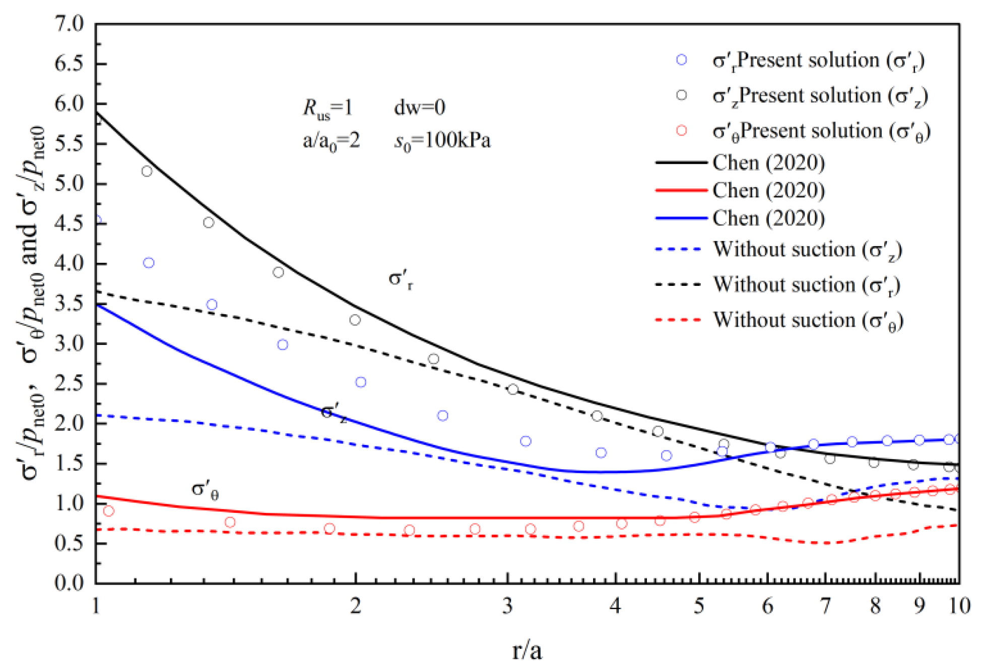
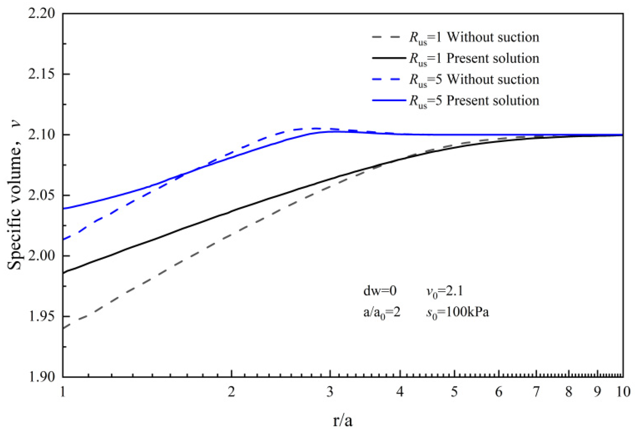
  • Both suction and the consolidation ratio affect the swelling response of unsaturated soils. Given that suction enhances the soil’s strength and rigidity, and the consolidation ratio enhances the yield stress, the radial distribution of both soil stress and specific volume are significantly affected.
  • Suction and the consolidation ratio significantly influence the saturation changes in the soil surrounding the cavity. Due to expansion, the average skeleton pressure escalates and the saturation decreases as the distance from the cavity wall grows, while the suction s is just the opposite, but both eventually tend to stabilize.
  • Suction significantly affects the coupled hydrodynamic behavior of the soil throughout the loading procedure. The initial suction increases, resulting in a rise in bias stress, and the soil demonstrates characteristics of suction hardening, stabilizing as the initial suction heightens. Meanwhile, as the initial suction increases, the p and v required for the soil to attain the critical condition are also larger.
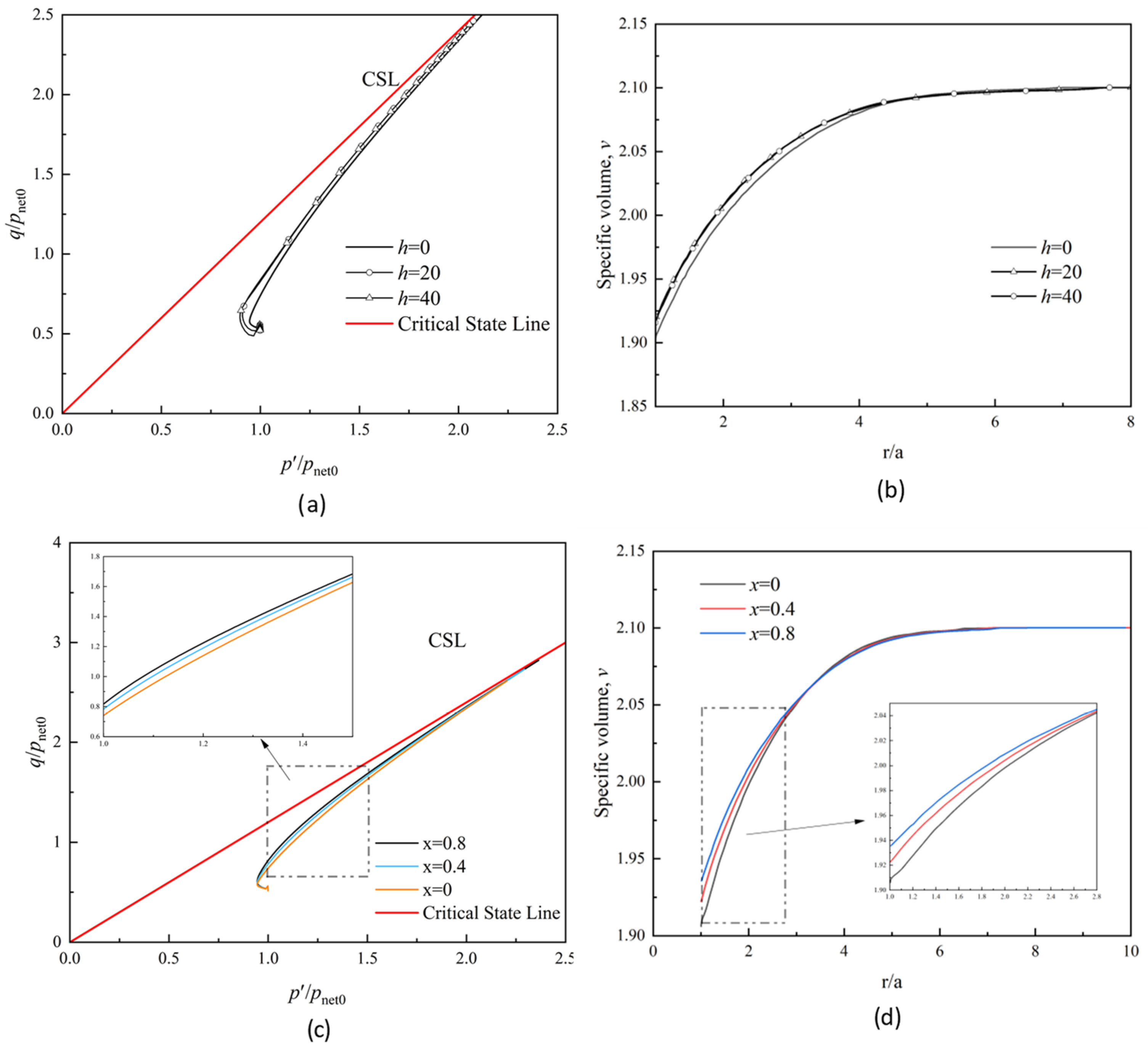
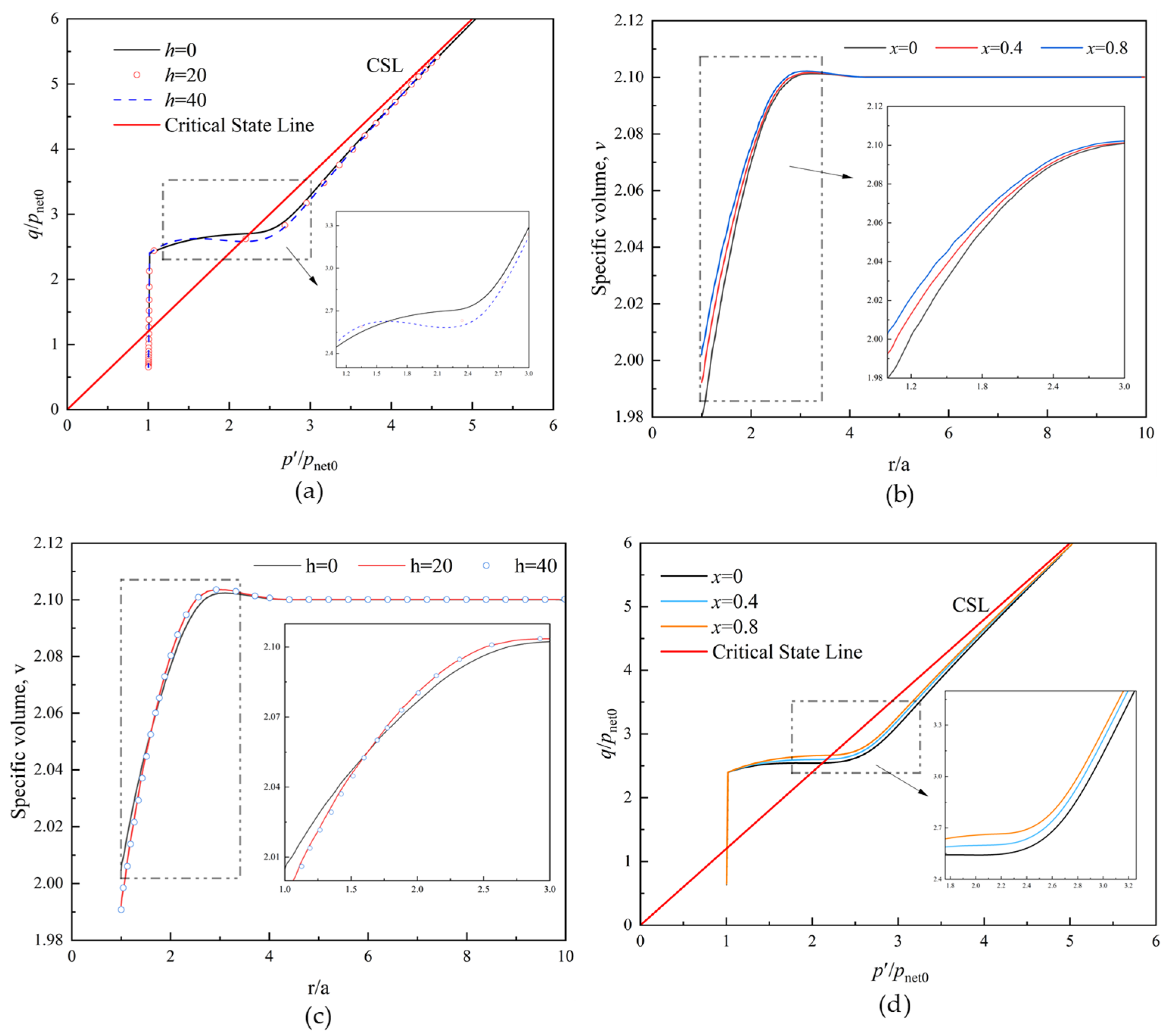
  • The development degree and rate of anisotropy in normally consolidated soil and over-consolidated soil exerts a substantial effect on the soil’s mechanical behavior. However, the model constant h controlling the rate of anisotropic development has a relatively small effect.
The solution achieves the broadening of the cylindrical cavity expansion theory for unsaturated soils from isotropic to anisotropic scenarios, offering a more universal analytical framework for unsaturated soil analysis, and furnishes theoretical backing for the soil’s mechanical behavior. However, the main comparison object of this article is Chen’s model, which may still be lacking in a direct comparison with field test data. Therefore, further improvements can be made in subsequent research.

Author Contributions

Conceptualization, J.C. and Y.J. (Yanhao Jin); methodology, J.C. and Y.J. (Yingjie Jing); software, Y.J. (Yanhao Jin); formal analysis, Y.J. (Yingjie Jing); investigation, Y.L.; resources, Y.J. (Yanhao Jin); data curation, Y.L.; writing—original draft preparation, J.C. and Y.J. (Yanhao Jin); writing—review and editing, Y.L. All authors have read and agreed to the published version of the manuscript.

Funding

This research was funded by the National Natural Science Foundation of China (grant 52108328).

Institutional Review Board Statement

Not applicable.

Informed Consent Statement

Not applicable.

Data Availability Statement

The data are contained within the article.

Conflicts of Interest

The authors declare no conflicts of interest.

Appendix A. Determination of Plastic Scalar Multiplier

The plastic scalar multiplier can be expressed as follows:
Λ = f p d p + f s i j d s i j + f p y p y s d s f p y p y p 0 y p ¯ 0 y + f α i j α ¯ i j = 1 K p f p d p + f s i j d s i j + f p y p y s d s
where
K p = f p y p y p 0 y p ¯ 0 y f α i j α ¯ i j
f p = 2 p p y + 3 2 M 2 p y α i j α i j 2 α i j s i j
f s i j = 3 M 2 s i j p α i j
f p y = p 3 α i j α i j 2 M 2 1
f α i j = 3 p M 2 p y α i j s i j
p y s = λ 0 λ 0 κ p y c 1 b e c s λ s κ 2 ln p 0 y p n
p y p 0 y = λ 0 κ λ s κ p 0 y p n λ 0 λ s λ s κ
d p = 1 3 d δ i j σ i j
d s i j = d σ i j p δ i j = d σ i j d p δ i j = d σ i j 1 3 δ m n d σ m n δ i j
p ¯ 0 y = 1 + e λ 0 κ p 0 y f p
α ¯ i j = 1 + e λ s κ f p c p y s i j x p α i j
p y = p 2 + 3 2 M 2 s i j p α i j s i j p α i j p 2 α i j α i j p 3 2 M 2 p α i j α i j

References

  1. Li, C.; Zou, J.F. Anisotropic elasto-plastic solutions for cavity expansion problem in saturated soil mass. Soils Found. 2019, 59, 1313–1323. [Google Scholar] [CrossRef]
  2. Russell, A.R.; Khalili, N. On the problem of cavity expansion in unsaturated soils. Comput. Mech. 2006, 37, 311–330. [Google Scholar] [CrossRef]
  3. Li, Y.J.; Chen, Y.M.; Ling, D.S. A general solution for the expansion of cavities in soil mass. China Civ. Eng. J. 2002, 35, 93–98. (In Chinese) [Google Scholar]
  4. Yang, C.Y.; Li, J.P.; Li, L. Expansion responses of a cylindrical cavity in over-consolidated unsaturated soils: A semi-analytical elastoplastic solution. Comput. Geotech. 2020, 130, 103922. [Google Scholar] [CrossRef]
  5. Carter, J.P.; Booker, J.R.; Yeung, S.K. Cavity expansion in cohesive frictional soils. Géotechnique 1986, 36, 349–358. [Google Scholar] [CrossRef]
  6. Wang, H.; Li, L.; Li, J.; Sun, D.A. Drained expansion responses of a cylindrical cavity under biaxial in situ stresses: Numerical investigation with implementation of anisotropic S-CLAY1 model. Can. Geotech. J. 2022, 60, 198–212. [Google Scholar] [CrossRef]
  7. Lade, P.V.; Duncan, J.M. Elastoplastic stress-strain theory for cohesionless soil. J. Geotech. Eng. Div. 1975, 101, 1037–1053. [Google Scholar] [CrossRef]
  8. Muravskii, G.B. On analytical description of stress-strain relationship for rocks and soils. Commun. Numer. Methods Eng. 1996, 12, 827–834. [Google Scholar] [CrossRef]
  9. Yan, B.; Wang, P.; Ren, F.; Guo, Q.; Cai, M. A review of mechanical properties and constitutive theory of rock mass anisotropy. Arab. J. Geosci. 2020, 13, 1–16. [Google Scholar] [CrossRef]
  10. Vatsala, A.; Nova, R.; Murthy, B.R.S. Elastoplastic model for cemented soils. Eng. J. Geotech. Geoenvironmental Eng. 2001, 127, 679–687. [Google Scholar] [CrossRef]
  11. Alonso, E.E.; Gens, A.; Josa, A.A. Constitutive model fo partially saturated soils. Géotechnique 1990, 40, 405–430. [Google Scholar] [CrossRef]
  12. Collins, I.F.; Yu, H.S. Undrained cavity expansion in critical state soils. Int. J. Numer. Anal. Methods Geomech. 1996, 20, 489–516. [Google Scholar] [CrossRef]
  13. Salgado, R.; Randolph, M.F. Analysis of cavity expansion in sand. Int. J. Geomech. 2001, 1, 175–192. [Google Scholar] [CrossRef]
  14. Russell, A.R.; Khalili, N. Drained cavity expansion in sands exhibiting particle crushing. Int. J. Numer. Anal. Methods Geomech. 2002, 26, 323–340. [Google Scholar] [CrossRef]
  15. Collins, I.F.; Pender, M.J.; Wang, Y. Cavity expansion in sands under drained loading conditions. Int. J. Numer. Anal. Methods Geomech. 1992, 16, 3–33. [Google Scholar] [CrossRef]
  16. Zhou, H.; Kong, G.Q.; Liu, H.L.; Laloui, L. Similarity solution for cavity expansion in thermoplastic soil. Int. J. Numer. Anal. Methods Geomech. 2018, 42, 274–294. [Google Scholar] [CrossRef]
  17. Chen, S.L.; Abousleiman, Y.N. Exact undrained elasto-plastic solution for cylindrical cavity expansion in modified Cam Clay soil. Géotechnique 2012, 62, 447–456. [Google Scholar] [CrossRef]
  18. Chen, S.L.; Abousleiman, Y.N. Exact drained solution for cylindrical cavity expansion in modified Cam Clay soil. Géotechnique 2013, 63, 510–517. [Google Scholar] [CrossRef]
  19. Chen, H.H.; Li, L.; Li, J.P.; Wang, H. Stress transform method to undrained and drained expansion of a cylindrical cavity in anisotropic modified cam-clay soils. Comput. Geotech. 2019, 106, 128–142. [Google Scholar] [CrossRef]
  20. Zhang, J.; Li, L. Similarity solution for undrained cylindrical cavity contraction in anisotropic modified Cam-clay model soils. Comput. Geotech. 2020, 120, 103405. [Google Scholar] [CrossRef]
  21. Russell, A.R.; Khalili, N. A unified bounding surface plasticity model for unsaturated soils. Int. J. Numer. Anal. Methods Geomech. 2006, 30, 181–212. [Google Scholar] [CrossRef]
  22. Wang, Z.; Zhen, Y.H. A bounding surface model for concrete constitutive relationship. Eng. Mech. 1999, 16, 120–129. (In Chinese) [Google Scholar]
  23. Wei, X.; Huang, M.S. Anisotropic bounding surface model for natural structured clays. Chin. J. Geotech. Eng. 2007, 29, 1224–1229. (In Chinese) [Google Scholar]
  24. Wei, X.; Huang, M.S. Anisotropic bounding surface model for clays. J. Hydraul. Eng. 2006, 37, 831–837. (In Chinese) [Google Scholar]
  25. Wei, X.; Huang, M.S. An anisotropic elastoplastic model for soft clays. Rock. Soil. Mech. 2007, 28, 1811–1816. (In Chinese) [Google Scholar]
  26. Yu, H.S. CASM: A unified state parameter model for clay and sand. Int. J. Numer. Anal. Methods Geomech. 1998, 22, 621–653. [Google Scholar] [CrossRef]
  27. Shao, W.; Qin, F.; Shi, D.; Soomro, M.A. Horizontal bearing characteristic and seismic fragility analysis of CFRP composite pipe piles subject to chloride corrosion. Comput. Geotech. 2024, 166, 105977. [Google Scholar] [CrossRef]
  28. Shao, W.; Li, Q.; Zhang, W.; Shi, D.; Li, H. Numerical modeling of chloride diffusion in cement-based materials considering calcium leaching and external sulfate attack. Constr. Build. Mater. 2023, 401, 132913. [Google Scholar] [CrossRef]
  29. Sun, D.A.; Sheng, D.; Xiang, L.; Sloan, S.W. Elastoplastic prediction of hydro-mechanical behaviour of unsaturated soils under undrained conditions. Comput. Geotech. 2008, 35, 845–852. [Google Scholar] [CrossRef]
  30. Chen, H.H.; Li, L.; Li, J.P. Elastoplastic solutions for cylindrical cavity expansion in unsaturated soils. Comput. Geotech. 2020, 123, 103569. [Google Scholar] [CrossRef]
  31. Lee, K.L.; Farhoomand, I. Compressibility and crushing of granular soil in anisotropic triaxial compression. Can. Geotech. J. 1967, 4, 68–86. [Google Scholar] [CrossRef]
  32. Lu, Y.; Ye, W.M.; Wang, Q.; Chen, Y.G. Insights into anisotropic swelling pressure of compacted GMZ bentonite. Acta Geotech. 2023, 18, 5721–5734. [Google Scholar] [CrossRef]
  33. Dafalias, Y.F. An anisotropic critical state soil plasticity model. Mech. Res. Commun. 1986, 13, 341–347. [Google Scholar] [CrossRef]
  34. Sun, D.A.; Sheng, D.; Sloan, S.W. Elastoplastic modelling of hydraulic and stress–strain behaviour of unsaturated soils. Mech. Mater. 2007, 39, 212–221. [Google Scholar] [CrossRef]
Figure 1. Diagrammatic sketch for cylindrical cavity expansion.
Jmse 12 00308 g001
Figure 2. Mapping of yield curve onto the p q flat.
Jmse 12 00308 g002
Figure 3. Comparison of the stress distribution of normally consolidated soil R us = 1 at time a / a 0 = 2 with Chen [30].
Jmse 12 00308 g003
Figure 4. Comparison of the stress distribution of normally consolidated soil R us = 5 at time a / a 0 = 2 with Chen [30].
Jmse 12 00308 g004
Figure 5. Change of specific volume along radial distance for R us = 1 and R us = 5 .
Jmse 12 00308 g005
Figure 6. Radial variation of normalized suction and saturation of soil around cavity for R us = 1 .
Jmse 12 00308 g006
Figure 7. Radial variation of normalized suction and saturation of soil around cavity for R us = 5 .
Jmse 12 00308 g007
Figure 8. Variation of standardized pressure components across radial extents: (a) R us = 1 (b) R us = 5 .
Jmse 12 00308 g008
Figure 9. Projection of stress trajectories on the p s plane.
Jmse 12 00308 g009
Figure 10. Change curve of specific volume under different initial suction when a / a 0 = 2 : (a) R us = 1 (b) R us = 5 .
Jmse 12 00308 g010
Figure 11. Soil mechanics properties of normal consolidated soil with different values of model constants x and h: (a) stress paths for disparate values of h; (b) specific volume at disparate values of h; (c) stress paths for disparate values of x; (d) specific volume at disparate values of x.
Jmse 12 00308 g011
Figure 12. Soil mechanics properties of over-consolidated soil under different model constants x and h: (a) stress paths for disparate values of h; (b) specific volume at disparate values of h; (c) stress paths for different values of x; (d) specific volume at different values of x.
Jmse 12 00308 g012
Table 1. Soil parameters with different over-consolidation ratios.
Rus σ h 0 σ v 0 pnet0K0Sr0 p 0 y p a
11602201200.730.6193.9193.9
51901601201.190.6917.4183.5
Table 2. Basic parameters of soil.
M b c λ ( 0 ) λ se λ sr   κ sr β v 0
1.20.650.1250.150.210.130.030.032.1
κ μ p at s I s D p n s 0 w 0   G s  
0.030.3100120401010024.09%2.74
Disclaimer/Publisher’s Note: The statements, opinions and data contained in all publications are solely those of the individual author(s) and contributor(s) and not of MDPI and/or the editor(s). MDPI and/or the editor(s) disclaim responsibility for any injury to people or property resulting from any ideas, methods, instructions or products referred to in the content.

