Article

Analysis of Holding Force Acting on Anchored Vessels

1
Department of Natural Science, Korea Naval Academy, Changwon 51704, Republic of Korea
2
Department of Aircraft MRO (Maintenance, Repair and Operation) Engineering, Howon University, Gunsan 54058, Republic of Korea
*
Author to whom correspondence should be addressed.
J. Mar. Sci. Eng. 2024, 12(1), 95; https://doi.org/10.3390/jmse12010095
Submission received: 14 December 2023 / Accepted: 31 December 2023 / Published: 2 January 2024

Abstract

:
In this paper, a mathematical and physical interpretation of the length and angle of the catenary curve made by anchor chains was implemented, and the safety of an anchored vessel was reviewed. So far, the holding force has usually been calculated when the angle of the catenary curve of the anchor chain to the seafloor is 0 ° . In this study, the holding force equation was strictly and explicitly derived considering the length of the chain and the depth of the sea. In addition, equations for the angle and length of the catenary curve were mathematically derived when anchor dragging occurs. The holding force equations derived in this paper are expected to help provide guidelines for vessel design or increase the safety of anchoring.

1. Introduction

Unlike cars that can park on the ground, vessels are impossible to be fixed on the sea. One of the safest ways to secure a vessel on the sea, besides mooring, is to use an anchor. Anchors can hold a vessel that weighs more than 1000 times its own weight. When a vessel is anchored, its safety is determined by the difference between the frictional force by the anchor and the various external forces acting on the vessel. When an anchor is dropped on the seafloor, the weight of the anchor makes it dig into the floor. Then, the frictional force of the anchor is greatly increased. The holding force is defined as the maximum static frictional force of the anchor [1,2].
The holding force is one of the most important indicators for the safety of anchored vessels. However, the holding force is a physical quantity that is hard to analyze because of various factors, such as friction on the seafloor; the big and complex shape of the vessel, which makes it difficult to estimate the external force; various catenary curves, which change the magnitude of the anchor chain’s tension; and so on. Estimating the holding force is known to be difficult, so the anchor’s holding force is usually measured by actually dragging anchors on the seafloor [3]. Nevertheless, theoretical and experimental studies on the holding force have been conducted occasionally in the field of geological oceanography and hydrodynamics. Ref. [4] theoretically analyzed the holding forces between tension and the shape of the catenary, and [5] carried out a reliability evaluation of the anchor’s holding force by the catenary curve. Ref. [6] examined the changes in holding force according to the seafloor composition and the angle of anchor fluke through model experiments. Ref. [7] studied the development of a prediction system in which operators check the expected situation of anchor dragging in missionary work. Ref. [8] derived the holding force motion equation through model experiments on the dragging of anchors on the seafloor. Ref. [9] studied the holding force in three stages according to the shape of the anchor when the seafloor composition was sand. Ref. [10] investigated the risks associated with drag embedment anchors for floating offshore wind turbines, emphasizing the impact of load angles on anchor design, uncertainties in postinstallation inspections, and the importance of ship specifications for anchor installation vessels with the goal of contributing insights to minimize trial and error in developing floating offshore wind power systems. Ref. [11] analyzed the equilibrium conditions of a ship’s anchor and cable during anchoring, considering three scenarios and introducing a coefficient to represent the effects of vertical cable tension on anchor holding force with a focus on safety considerations and numerical examples. Ref. [12] conducted 240 laboratory tests and proposed a formula based on embedded depth, net weight, geometry, and soil properties for accurate estimation of the undrained monotonic holding capacity of torpedo anchors, demonstrating consistency with both laboratory and field data for effective mooring system design in soft sedimentary beds. Ref. [13] investigated the optimal design of expanded head bolts to address inadequate traditional bolt supports in complex geological conditions, revealing that factors such as front and rear end bearing capacity, side bearing capacity, and side friction resistance influence the drawing capacity of the bolt, with circular table-shaped tensile bolts exhibiting the highest pull-out force and representing the best design. Ref. [14] addressed the design of anchor foundations for civil engineering structures subjected to upward load action, proposing the use of physical modeling with two parameters obtained from laboratory tests on different scale models to predict the ultimate pulling capacity and pull–rise curve and providing a reasonably accurate methodology for analyzing the complex soil foundation system of under-reamed anchor pile foundations in soft clay.
In addition, case studies on anchoring and application studies for the design of anchoring have been conducted [15,16,17,18,19,20].
In a general situation, the safety of the anchored vessel can be controlled by adjusting the released length of anchor chains. However, in harsh environments, such as typhoons, it is difficult to secure the safety of the vessel just by controlling the released length of anchor chains. If the net external force caused by the winds, currents, and waves exceeds the holding force of an anchor, anchor dragging occurs. Then, the vessel eventually leaves the anchoring point and strands on a sandbank or collides with other vessels. When a typhoon is about to hit, vessels usually deviate far from the expected route of the typhoon or select a less dangerous area to anchor. However, judgment on the anchoring area and the vessel’s safety after anchoring still depends on the experience of the operators. The authors of [21] investigated 62 maritime accidents that occurred during the invasion of Typhoon Maemi (category 5) in Jinhae Bay, the Republic of Korea, in 2003 and published the results as a manual for anchored vessels in 2009. Other researchers have simulated the anchor dragging of vessels under bad weather, including typhoons, or presented guidelines by studying them based on real situations [22,23,24,25].
The holding force of an anchor is a complicated function related to the shape of the anchor chain’s catenary curve generated by external forces. Therefore, it is not sufficient to independently study the frictional force of anchors using geological oceanography or the external forces of vessels using fluid dynamics. It can be said that a given system can be properly understood only by considering the physical relationship between the external forces of the vessel and the holding force of the anchor, which are transmitted by the anchor chain. In this study, we estimated the conditions in which anchor dragging occurs and then calculated the holding force theoretically.
The contents of this paper are as follows. In Section 2, the forces of an anchored vessel as a physical system are described. In Section 3.1, we derive the tension and length of the anchor chain as functions of depth and tangential angle between the anchor chain and the seafloor. In Section 3.2, we derive equations considering the length of the chain’s holding part and the tangential angle. Then, in Section 3.3, we derive holding force equations for cases with or without a holding part. Finally, in Section 4, we summarize and discuss the results.

2. Materials

Vessels usually anchor to securely fix their position on the sea. When an external force, such as wind, acts on the vessel, anchors with chains resist external force through friction on the seafloor. In normal cases, the external force and the frictional force are in equilibrium with each other. However, when the external force increases, the anchors and chains receive upward forces derived from the catenary shape of the chain, so the frictional force due to the anchor and chains is reduced. Moreover, if external force exceeds a threshold, the anchor and chains on the seafloor cannot play their role and the anchor is eventually dragged.
Figure 1 shows the shapes of catenary curves according to the magnitude of the external force acting on an anchored vessel. The process of anchor dragging is as follows.
If the frictional forces generated by the anchor and the holding part of the chain are insufficient for the external force, anchor dragging occurs even if the length of the holding part is not 0.
Figure 2a shows all the forces acting on a vessel. If we neglect the vertical motion of a vessel caused by a wave, we can consider only the horizontal forces because all vertical forces are canceled out by each other. Figure 2b shows horizontal forces, i.e., external force ( F e x t ); horizontal components of tension T x ; and frictional force on seafloor f .
Table 1 shows all the forces constituting these three horizontal forces and the independent variables that determine them.
In most cases, the external force F e x t , the horizontal tension T x , and the friction force f are balanced with each other, so anchor dragging does not occur. However, in an extreme situation where the external force is bigger than the frictional force, anchor dragging occurs, and the system of mass M , constituting of the vessel, chain, and anchor, accelerates as shown in Equation (1) according to Newton’s second law.
a = F e x t f M
Let the holding force H be the maximum static frictional force generated by the anchor and the chains on the seafloor. When there is no anchor dragging, the external force must be smaller than the holding force. However, the external force exceeds the holding force when anchor dragging occurs. Equation (2) shows the relationships between the forces when anchor dragging does or does not occur.
F e x t = T x = f < H ,             no   anchor   dragging F e x t T x f = H ,           at   anchor   dragging

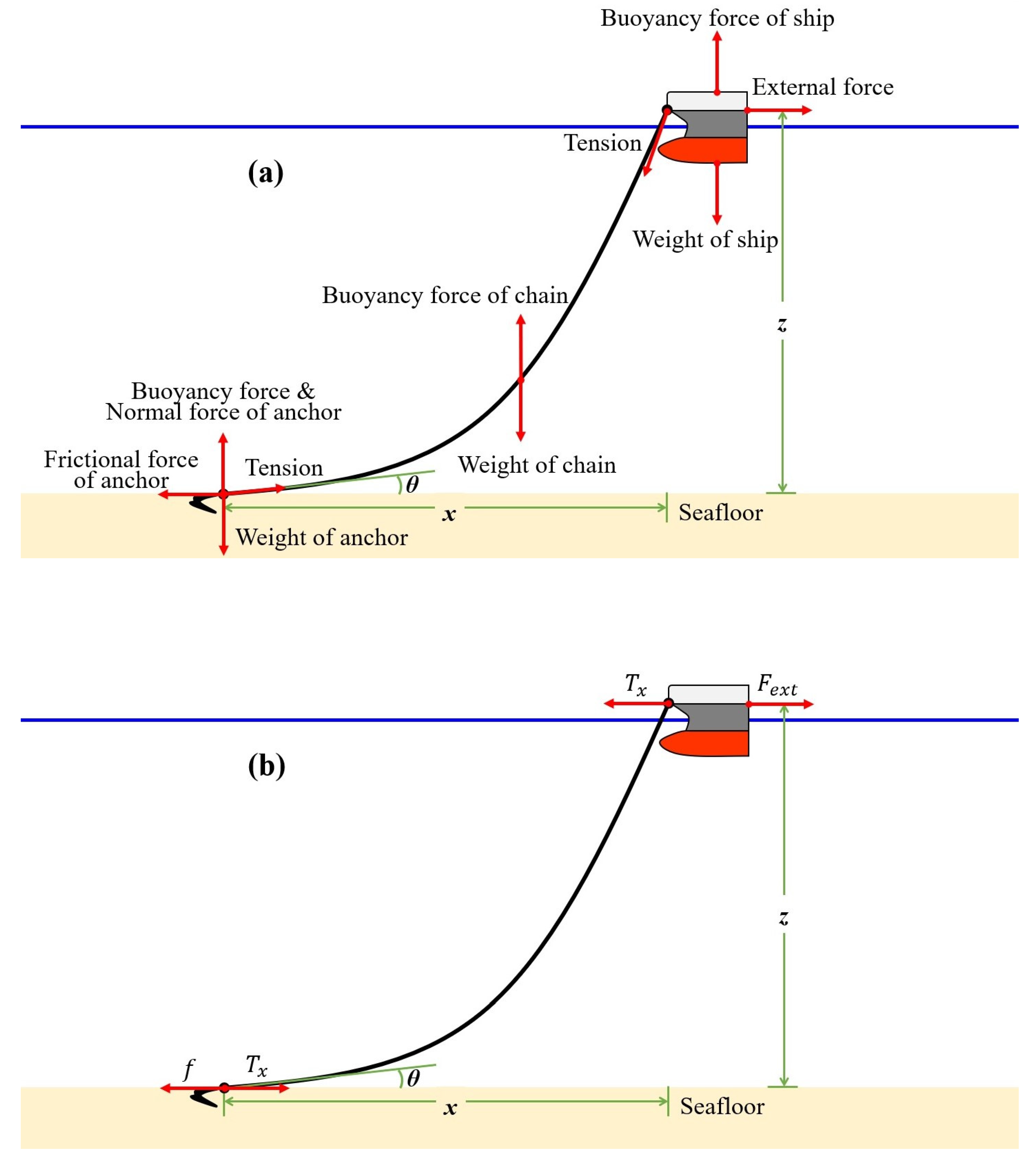
3. Analysis of Holding Force

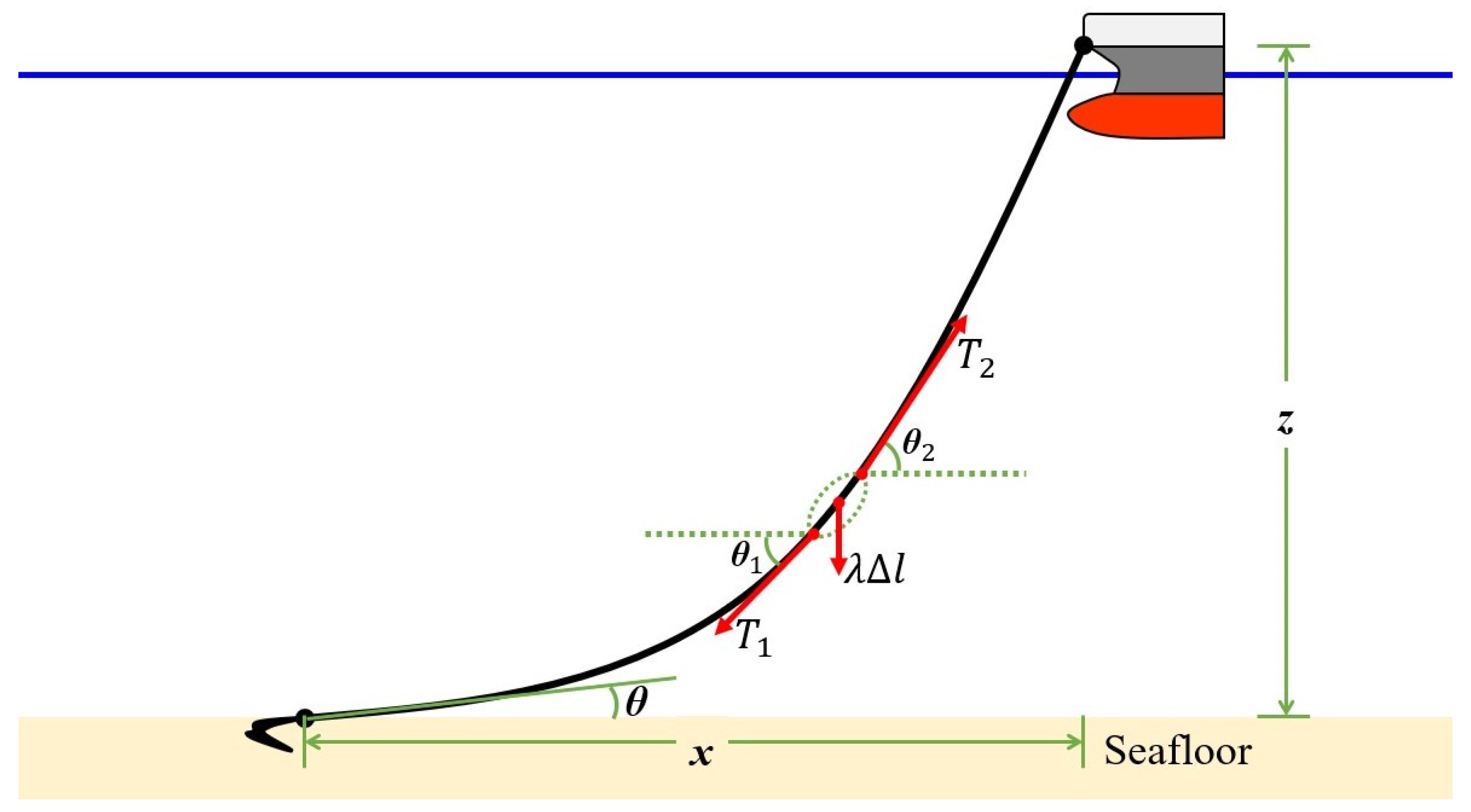
3.1. Tension of Catenary Curved Chain

The tension acting on a catenary curved chain depends on the weight per unit length of the chain. Figure 3 is a diagram showing the three forces: ① λ Δ l is the weight of infinitesimal length Δ l of the chain in the seawater where the weight per unit length in the seawater is λ , and ② tension T 1 and T 2 act on both ends of Δ l . According to Figure 3, the horizontal component and vertical component of T 1 and T 2 must satisfy Equation (3).
T 1 cos θ 1 = T 2 cos θ 2 = constant   ,                     x component T 1 sin θ 1 + λ l = T 2 sin θ 2 ,                                           z component
where λ is the weight per unit length, Δ l is the infinitesimal length of the chain, and T 1 and T 2 are tensions acting on both ends of Δ l .
With some calculations, we could derive Equations (4)–(6), giving the vertical coordinates z of the vessel, the length l of the catenary part, and the horizontal tension T x for tangential angles θ , respectively. For the derivation of the equations, refer to Appendix A.
z = T x λ cosh λ T x x + s i n h 1 t a n θ s e c θ
l = T x λ sinh λ T x x + s i n h 1 t a n θ t a n θ
T x = λ 2 l 2 z 2 z s e c θ l t a n θ

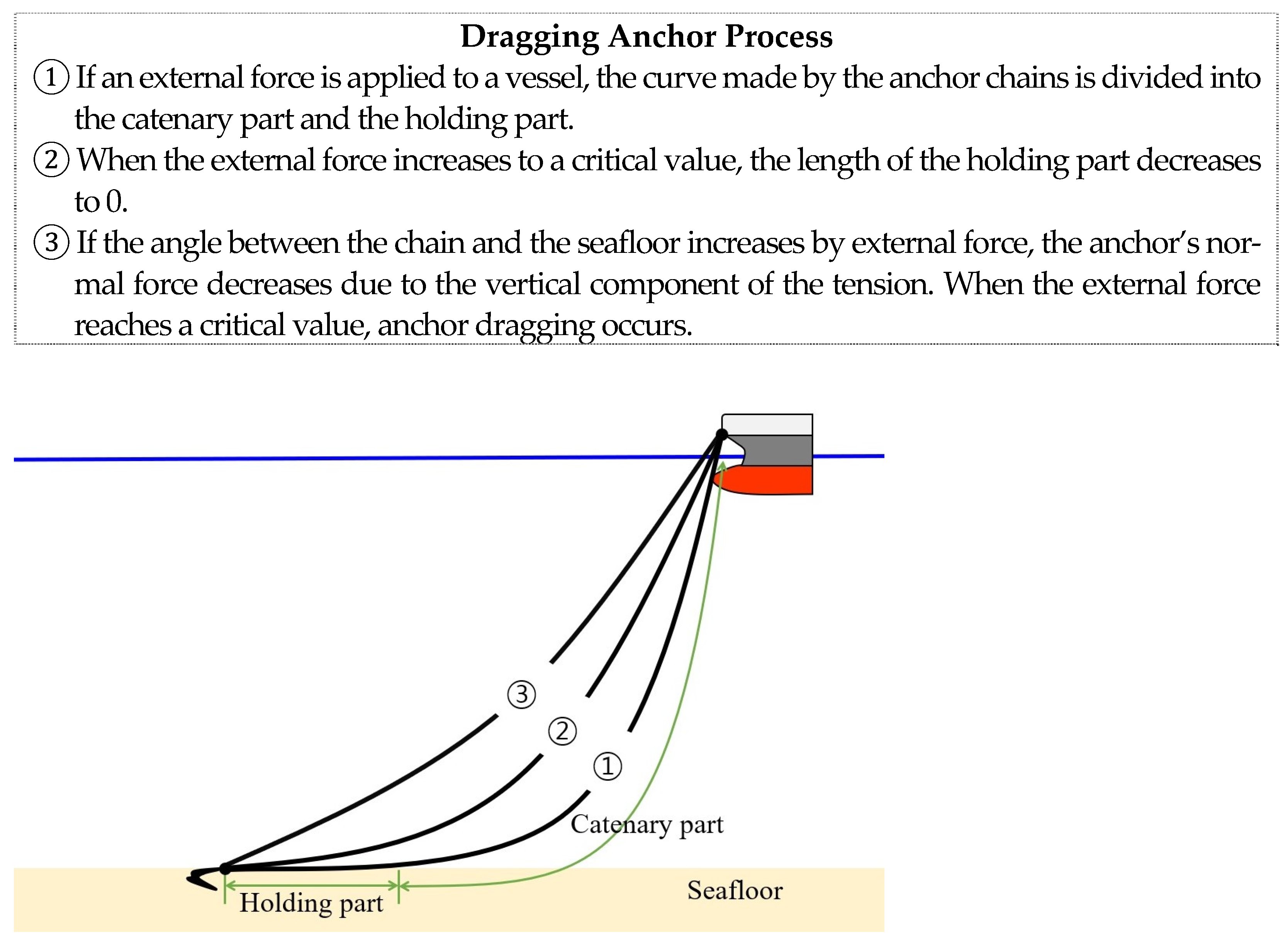
3.2. Holding Force before Anchor Dragging: F e x t = T x < H

Anchor is usually dropped into the sea to keep a vessel in place. If an anchor alone is not enough to secure the vessel, concrete sinkers may be added to the anchor to increase the holding force. Figure 4 compares two cases that represent the shape of the catenary part when a sinker exists. Figure 4a represents the case where the tangential angle θ between the catenary part of the anchor chain and the seafloor is 0 ° . Then, the chain of length l 0 is divided into a holding part of length d and a catenary part of length l = l 0 d . Figure 4b represents the case where there is no holding part. In this case, angle θ is bigger than 0 ° .
Equations (7) and (8) show the length d of the holding part and the angle θ between the catenary and the seafloor using T x and z as independent variables. For the derivation of the equations, refer to Appendix B.
  • Cases where there is a holding part: d 0   ( θ = 0 ° )
d = l 0 z 2 + 2 T x λ z
  • Cases when there is no holding part: d = 0   ( θ > 0 ° )
θ = t a n 1 λ l 2 T x + 1 2 λ l T x 2 λ 2 l 2 z 2 T x 2 4 z 2 l 2 z 2
Now, consider the holding forces taking into account the anchor, sinker, and chain. Because the sinker is connected to the catenary curved chain, the normal force of the sinker is changed by the shape of the curve. However, the normal force of the anchor is constant, so the holding force due to the anchor is a constant value, as shown in Equation (9).
H a = μ a w a ,
where μ a is the holding coefficient of the anchor, and w a is the weight of the anchor in the water.
Equation (10) shows the holding force of the chains is proportional to the length of the chains lying on the seafloor.
H c = μ c w c = μ c λ ( d + d 0 ) ,
where μ c is the holding coefficient of chain, w c is the weight of the chains lying on the seafloor, λ is the weight of the chains per unit length, d 0 is the length of the chains between the anchor and the sinker, and d is the length of the holding part.
Finally, as shown in Equation (11), the holding force of the sinker is proportional to the normal force of the sinker. In this case, the normal force of the sinker is reduced due to the vertical component of tension.
H s = μ s ( w s T x t a n θ ) ,
where μ s is the holding coefficient of the sinker, w s is the weight of the sinker in the water, and T x is the horizontal component of tension.
Thus, total holding force on the system can be written as in Equation (12).
H = H a + H c + H s = μ a w a + μ c λ ( d + d 0 ) + μ s ( w s T x t a n θ )

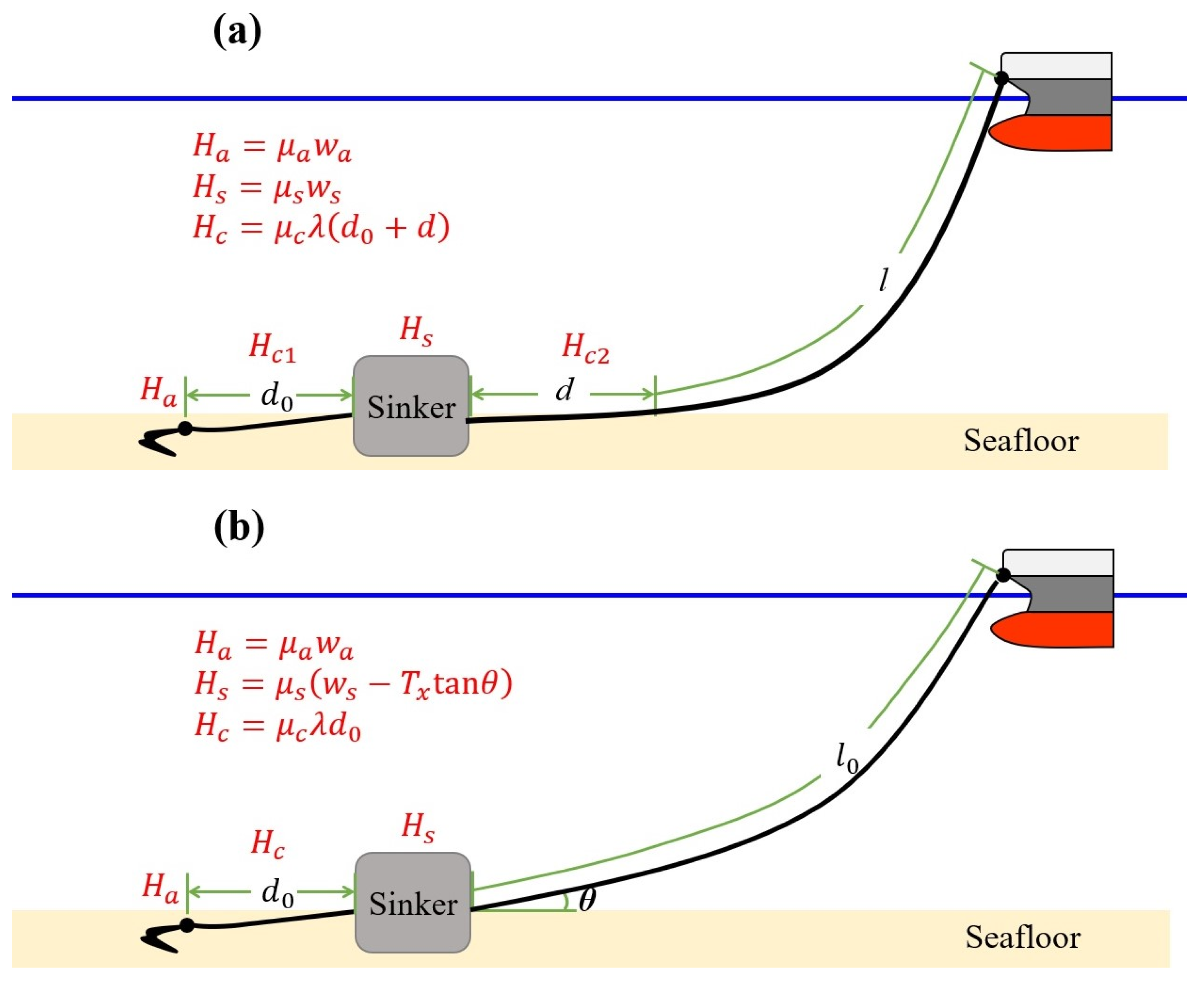
3.3. Holding Force at Anchor Dragging: F e x t = T x = H

When the external force, tension, and holding force are balanced with each other (i.e., F e x t = T x = H ), anchor dragging occurs. Therefore, by putting T x = H and substituting T x in Equations (6), (11) and (12) with H , we could derive holding force Equations (13) and (14) when anchor dragging occurs.
H = λ 2 l 2 z 2 z s e c θ l t a n θ
H = μ a w a + μ s w s + μ c λ ( d + d 0 ) 1 + μ s t a n θ
When the chain is released sufficiently, the length of the holding part d is greater than 0, resulting in the tangential angle of 0° between the chain and the seafloor. Anchor dragging may also occur in this case. Equations (15) and (16) show the length of the holding part d and the holding force H at the moment of anchor dragging when a holding part exists. For the derivation of the equations, refer to Appendix C.
  • Where there is a holding part: d 0   ( θ = 0 ° )
d = l 0 + μ c z { 1 + μ c 2 z 2 + 2 A + μ c l 0 z
H = λ A + μ c λ l 0 + μ c z 1 + μ c 2 z 2 + 2 A + μ c l 0 z
A μ a w a + μ s w s + μ c λ d 0 / λ
The length of the holding part d should not be negative in Equation (15). Thus, in this case, it can be considered that the tangential angle θ between the chain and the seafloor is greater than 0°. Equations (17) and (18) show the tangential angle θ and the holding force H at the moment of anchor dragging when a holding part does not exist. Equations (15)–(18) show that anchor dragging can occur in both cases, i.e., with or without a holding part. For the derivation of the equations, refer to Appendix C.
  • Where there is no holding part: d = 0   ( θ > 0 ° )
θ = t a n 1 Π + Π 2 Ξ Σ Ξ
    H = μ a w a + μ s w s + μ c λ d 0 1 + μ s Π + Π 2 Ξ Σ Ξ
Ξ A l + B μ s 2 A 2 z 2 ,   Π B A l + B μ s ,   Σ B 2 A 2 z 2   with A μ a w a + μ s w s + μ c λ d 0 / λ ,   B l 2 z 2 / 2
Table 2 shows the ratio of holding force using Equation (14) according to the holding coefficients of the anchor (sinker) and the tangential angle between the anchor (sinker) and the seafloor. By Dove’s experiment, it is known that the holding force decreases by 1/4 when θ = 5 ° and decreases by 1/2 when θ = 15 ° [5,26]. However, we can see Dove’s results are consistent only if the holding coefficient is about 4 in Table 2. This inconsistency means that the prediction of the decreasing ratio of the holding forces only by the tangential angle θ can give us inaccurate information because the holding force depends on two factors: θ and μ a ( μ s ).

4. Conclusions

We examined the safety of vessels by studying the holding force acting on anchored vessels. The holding force of an anchor was strictly analyzed by a mathematical and physical approach, which has been known to be a difficult problem in the field of shipbuilding engineering and navigation. In order to predict and prevent anchor dragging in extreme situations, such as typhoons, this study mathematically and physically analyzed the tension of the anchor chain by deducing the catenary curve equation and holding force of the anchor and then strictly examining the relationship between tension and holding force.
The force acting on the anchor was analyzed, and the horizontal component of tension was newly derived as a function of the depth of the sea, the length of the catenary part, and the angle with the seafloor (Equation (6)). Moreover, the holding force for a vessel with a sinker attached was analyzed. The anchor chains transmit the external force to the sinker (anchor). When the external force exceeds the threshold, anchor dragging occurs in both cases with or without the holding part of the anchor chain. If there is no holding part, the holding force decreases due to the decrease in normal force of the sinker (anchor). In this case, to make the anchor and the sinker play their intended roles, it is necessary to increase the number of released anchor chains. However, as the length of the released anchor chain increases, the radius of movement of vessels increases, so the risk of collisions with other vessels or structures may increase. Therefore, the safety of anchored vessels should be increased by controlling the amount of released chain according to the situation. In this study, the angle between the holding part and the seafloor, the length of the holding part, and the holding force were systemically derived (Equations (15)–(18)). The larger the coefficient of friction and angle between the anchor and the seabed, the more the holding force decreases. If the coefficient of friction is 4, the holding force decreases by about 1/4 when the angle is 5 ° and about 1/2 when the angle is 15 ° . However, if the coefficient of friction is 12, the holding force decreases by about 1/2 when the angle is 5 ° and about 3/4 when the angle is 15 ° . Even when the coefficient of friction is 12 and the angle is 60 ° , only 4.5% is exhibited compared to when the angle is 0 ° (Table 2).
With these results, we could provide more symbolic equations describing the anchor dragging moments instead of the conventional method of using inaccurate approximation values. In this paper, the circulating load due to external forces, such as waves, was not considered. Research through actual experiments or cases will be required to further verify the theory. However, the holding force equations derived in this paper could provide more accurate ways for vessel design and improved guidelines for preventing anchor dragging. The conventional method mainly involves calculating the angle between the seafloor and the anchor chain as 0 degrees using the suspension line equation in a simple case and further verifying it through experiments. We calculated the holding force through rigorous calculation even when the angle of interference is not 0 degrees. In addition, holding force estimation is possible for anchored structures as well as general vessels as the calculations were performed for a vessel with a sinker attached. In the future, if additional research is conducted on various anchor dragging cases, the safety of anchored vessels in a harsh environment may be further explored.

Author Contributions

Conceptualization, S.M. and K.O.; methodology, S.M.; validation, K.O.; writing—original draft preparation, S.M.; writing—review and editing, K.O.; funding acquisition, S.M. All authors have read and agreed to the published version of the manuscript.

Funding

This work was supported by the Korea Naval Academy Maritime Institute in 2023.

Data Availability Statement

No new data were created or analyzed in this study. Data sharing is not applicable to this article.

Conflicts of Interest

The authors declare no conflicts of interest.

Appendix A. Forces at a Catenary Curve

In the catenary part, when λ is the weight per unit length of the catenary part, the weight of infinitesimally small length Δ l is λ Δ l . Let T 1 and T 2 be the tensions acting on both ends of Δ l and let the angles be θ 1 and θ 2 at two horizontal ends. Then, the horizontal components of the two tensions must be the same, but the vertical components are different by λ Δ l (see Figure 3).
Then,
T 1 cos θ 1 = T 2 cos θ 2 = constant   ,                       x component T 1 sin θ 1 + λ l = T 2 sin θ 2 ,                                             z component
Hence,
λ d l = d T s i n φ
Thus,
λ d l = λ d x 2 + d z 2 = λ 1 + z 2 d x
d T s i n φ = d T c o s φ t a n φ = d T x t a n φ = T x d z
T x = T c o s φ = c o n s t a n t ,   z = d z / d x = t a n φ
Then,
λ 1 + z 2 d x = T x d z
λ T x d x = d z 1 + z 2
If both sides are integrated with respect to x  and z ,
λ T x x = s i n h 1 z s i n h 1 z 0
z 0 = tan θ ,
z = sinh λ T x x + s i n h 1 z 0 = sinh λ T x x + s i n h 1 tan θ
The vertical coordinates of the vessel can be derived as shown in Equations (A9) by integration of Equation (A8).
  • Vertical coordinate of the anchored vessel:
z = T x λ   cosh λ T x x + s i n h 1 tan θ sec θ   ;         g e n e r a l c a s e T x λ   cosh λ T x x                                                                             ;         θ = 0
The length of the catenary part is derived through integration as shown in Equation (A10).
l = 0 x 1 + z 2 d x
= 0 x 1 + sinh 2 λ T x x + s i n h 1 tan θ d x
= 0 x cosh λ T x x + s i n h 1 tan θ d x
  • Length of the catenary part:
l = T x λ   sinh λ T x x + s i n h 1 tan θ tan θ   ;   g e n e r a l c a s e T x λ   sinh λ T x x                                                                               ;   θ = 0
Now, we can obtain a general formula for horizontal tension using the relationship between z = z x , θ and l = l x , θ by combining Equations (A9) and (A11).
As cosh 2 t sinh 2 t = 1 is satisfied for any t ,
λ z T x + sec θ 2 λ l T x + tan θ 2 = 1
Finally, T x is summarized as shown in Equation (A13).
  • Horizontal tension of the catenary
T x = λ 2 l 2 z 2 z s e c θ l t a n θ

Appendix B. Before Anchor Dragging

In normal cases where no anchor drag occurs, let the length of the holding part be d . Then, from Equation (A13), we can obtain the following equations for d and θ .
  • Where there is a holding part: d 0 θ = 0 °
T x = λ 2 z l 0 d 2 z 2
d = l 0 z 2 + 2 T x λ z
  • Where there is no holding part: d = 0 ( θ > 0 ° )
T x = λ 2 l 2 z 2 z s e c θ l tan θ
z s e c θ = l tan θ + λ l 2 z 2 2 T x
By squaring Equation (A17) using sec 2 θ = tan 2 θ + 1 ,
tan 2 θ + λ l T x tan θ + λ 2 l 2 z 2 4 T x 2 z 2 l 2 z 2 = 0
θ = t a n 1 λ l 2 T x + 1 2 λ l T x 2 λ 2 l 2 z 2 T x 2 4 z 2 l 2 z 2

Appendix C. At the Moment of Anchor Dragging

The horizontal part of the chain’s tension and the anchor’s holding force are given in Equations (A20)–(A21).
T x = λ 2 l 2 z 2 z s e c θ l t a n θ
H = μ a w a + μ s w s + μ c λ d + d 0 1 + μ s tan θ
When anchor dragging occurs, the horizontal tension T x and the holding force H of the system should be equal.
  • Where there is a holding part: d 0   ( θ = 0 ° )
H = λ l 0 d 2 z 2 2 z = μ a w a + μ s w s + μ c λ d + d 0
l 0 d 2 z 2 = 2 z μ c d + A
A μ a w a + μ s w s + μ c λ d 0 / λ
d 2 2 l 0 + μ c z d + l 0 2 z 2 2 A z = 0
If the solution of Equation (A24) is substituted for Equation (A21), then,
d = l 0 + μ c z { 1 + μ c 2 z 2 + 2 A + μ c l 0 z
H = λ A + μ c λ d       = λ A + μ c λ l 0 + μ c z 1 + μ c 2 z 2 + 2 A + μ c l 0 z
;   A μ a w a + μ s w s + μ c λ d 0 / λ
  • Where there is no holding part: d = 0 ( θ > 0 ° )
From Equations (A20)–(A21),
H = λ 2 l 2 z 2 z s e c θ l t a n θ = μ a w a + μ s w s + μ c λ d 0 1 + μ s tan θ
A 1 + μ s tan θ = B z s e c θ l t a n θ
  A μ a w a + μ s w s + μ c λ d 0 / λ ,   B l 2 z 2 / 2
A z s e c θ l t a n θ = B 1 + μ s tan θ
A l + B μ s tan θ + B = A z s e c θ
A l + B μ s 2 tan 2 θ + 2 B A l + B μ s tan θ + B 2 = A 2 z 2 tan 2 θ + 1
A l + B μ s 2 A 2 z 2 tan 2 θ + 2 B A l + B μ s tan θ + B 2 A 2 z 2 = 0
By squaring Equation (A30) using sec 2 θ = tan 2 θ + 1 ,
A l + B μ s 2 tan 2 θ + 2 B A l + B μ s tan θ + B 2 = A 2 z 2 tan 2 θ + 1
A l + B μ s 2 A 2 z 2 tan 2 θ + 2 B A l + B μ s tan θ + B 2 A 2 z 2 = 0
If the quadratic equation solution of Equation (A34) is substituted for Equation (A21) and solved, we can obtain θ 0 and H at the moment of anchor dragging, as shown in Equations (A35)–(A36).
θ = tan 1 Π + Π 2 Ξ Σ Ξ
H = μ a w a + μ s w s + μ c λ d 0 1 + μ s Π + Π 2 Ξ Σ Ξ
Ξ A l + B μ s 2 A 2 z 2 ,   Π B A l + B μ s ,   Σ B 2 A 2 z 2   with A μ a w a + μ s w s + μ c λ d 0 / λ ,   B l 2 z 2 / 2

References

  1. Lim, B.-T.; Ko, J.-W.; Kim, B.-S. A study on theoretical consideration to the holding power and holding power coefficient of war vessel anchor. J. Navig. Port Res. 2015, 39, 1–6. [Google Scholar] [CrossRef]
  2. Kim, M.-S.; Ahn, J.-Y.; Lee, C.-H. Evaluation of Holding Power by Tension Meter for Anchoring. J. Fish. Mar. Sci. Educ. 2019, 99, 682–692. [Google Scholar]
  3. Sato, H. A study on the holding capacity of anchor. J. Sch. Mar. Sci. Technol. Tokai Univ. 2005, 3, 31–39. [Google Scholar]
  4. Shoji, K. Study on the motion of a moored body and the tension of mooring lines. Soc. Nav. Archit. Jpn. 1975, 138, 233–246. [Google Scholar] [CrossRef] [PubMed]
  5. Moharrami, M.J.; Shiri, H. Reliability assessment of drag embedment anchors in clay for catenary mooring systems. Mar. Struct. 2018, 58, 342–360. [Google Scholar] [CrossRef]
  6. O’Neill, M.P.; Bransby, M.F.; Randolph, M.F. Drag anchor fluke soil interaction in clays. Can. Geotech. J. 2003, 40, 78–94. [Google Scholar] [CrossRef]
  7. Okazaki, T.; Hirai, Y. Development of a support system to predict dragging anchor phenomenon for mariner. In Proceedings of the 2011 6th International Conference on System of Systems Engineering, Albuquerque, NM, USA, 27–30 June 2011; IEEE: New York, NY, USA, 2011; pp. 185–190. [Google Scholar]
  8. Liu, H.; Liu, C.; Yang, H.; Li, Y.; Zhang, W.; Xiao, Z. A novel kinematic model for drag anchors in seafloor soils. Ocean Eng. 2012, 49, 33–42. [Google Scholar] [CrossRef]
  9. Ren, X.Y.; Lei, Z.M.; Sun, L.; Yan, S. Model tests of dragging hall anchors in sand. J. Mar. Sci. Technol. 2016, 24, 26–31. [Google Scholar]
  10. Yoon, S.; Joung, T. Risk on design & installation of drag embedment anchor (DEA) for floating offshore wind turbine (FOWT). J. Int. Marit. Saf. Environ. Aff. Shipp. 2022, 6, 199–205. [Google Scholar]
  11. Ueno, M. Analysis of Holding Force Limit and Provision against Dragging Anchor. J. Waterw. Port Coast. Ocean. Eng. 2022, 148, 04021042. [Google Scholar] [CrossRef]
  12. Wang, W.; Wang, X.; Yu, G. Vertical holding capacity of torpedo anchors in underwater cohesive soils. Ocean. Eng. 2018, 161, 291–307. [Google Scholar] [CrossRef]
  13. Zhang, S.; Wang, Y.; Li, C.; Wang, C.; Zhang, G.; Sun, S. Study on the Style Design and Anchoring Mechanism of Enlarged Head Anchors. Sustainability 2023, 15, 8645. [Google Scholar] [CrossRef]
  14. Golait, Y.S.; Padade, A.H.; Cherian, T. Prediction of Quantitative Response of Under-Reamed Anchor Piles in Soft Clay Using Laboratory Model Study. J. Test. Eval. 2018, 46, 507–522. [Google Scholar] [CrossRef]
  15. Thorne, C.P. Penetration and Load Capacity of Marine Drag Anchors in Soft Clay. J. Geotech. Geoenvironmental Eng. 1998, 124, 945–953. [Google Scholar] [CrossRef]
  16. Navy. Design Criteria of Anchor and Anchor Chain; Naval vesselbuilding(SU)-GI-06-007(2004); Navy: Oklahoma City, OK, USA, 2004. [Google Scholar]
  17. Mierlo, R.V. Anchor Trajectory Modeling; Faculty of Mechanical Engineering, Offshore Engineering Major, Delft University of Technology: Delft, Switzerland, 2005. [Google Scholar]
  18. Murff, J.D.; Randolph, M.F.; Elkhatib, S.; Kolk, H.J.; Ruinen, R.M.; Strom, P.J.; Thorne, C.P. Vertically Loaded Plate Anchors for Deepwater Applications. In Frontiers in Offshore Geotechnics ISFOG; Taylor & Francis: Abingdon, UK, 2005. [Google Scholar]
  19. Ruinen, R.M. Influence of Anchor Geometry and Soil Properties on Numerical Modeling of Drag Anchor Behavior in Soft Clay. In Frontiers in Offshore Geotechnics ISFOG; Taylor & Francis: Abingdon, UK, 2005. [Google Scholar]
  20. Miedema, S.A.; Lagers, G.H.G.; Kerkvliet, J. An Overview of Drag Embedded Anchor Holding Capacity for Dredging and Offshore Applications; WODCON: Orlando, FL, USA, 2007. [Google Scholar]
  21. Jung, C.-H.; Kong, G.-Y. A Study on the Development of Anchoring Manual for T.S. HANBADA. J. Kor. Soc. Mar. Environ. Saf. 2009, 15, 49–55. [Google Scholar]
  22. Lee, Y.-S.; Jung, Y.-C.; Kim, S.-W.; Yun, J.-H.; Bae, S.-H.; Guyen, P. A Study on the Limit of Anchor Dragging for Vessel at Anchor (I). J. Navig. Port Res. 2005, 29, 357–363. [Google Scholar] [CrossRef]
  23. Jung, C.-H.; Kong, G.-Y.; Bae, B.-D.; Lee, Y.-S. Analysis on the Pattern of Dragging Anchor in Actual Vessel. J. Navig. Port Res. 2009, 33, 505–511. [Google Scholar] [CrossRef]
  24. Jung, C.-H.; Lee, Y.-S.; Kim, J.-S.; Kong, G.-Y. A Study on the Holding Power Coefficient of AC-14 type and ASS type Anchor in Actual Vessels. J. Navig. Port Res. 2011, 35, 613–618. [Google Scholar] [CrossRef]
  25. Jung, C.-H.; Kong, G.-Y. A Study for the Evaluation of the Force by the Wind on the Vessel at Anchoring. Korean Soc. Mar. Environ. Saf. 2009, 15, 223–228. [Google Scholar]
  26. Yoon. The Theory and Executive Ability of Ship Control; Se-Jong Publisher: Seongnam, Republic of Korea, 2014; pp. 1–15. [Google Scholar]
Figure 1. Shape of catenary curve on an anchored vessel according to external forces.
Jmse 12 00095 g001
Figure 2. Forces acting on anchored vessel system: (a) all forces are expressed, (b) horizontal components need to be considered.
Jmse 12 00095 g002
Figure 3. Tension acting on a small length Δ l in the catenary.
Jmse 12 00095 g003
Figure 4. Holding force according to the shape of the catenary: (a) θ = 0 ° ( d 0 ); (b) θ > 0 ° ( d = 0 ).
Jmse 12 00095 g004
Table 1. Constituting forces and variables of horizontal forces.
ForcesConstituting ForcesVariables
F e x t F w i n d : wind-driven force v a : wind speed
F c u r r e n t : current-induced hydraulic force v w : current speed
F w a v e : drift force by wave h : wave height
T x T x : horizontal component of tension( x ,   z ) : position of vessel (origin: anchor)
l : length of catenary
θ : angle
f f a : frictional force by anchor
f c : frictional force by anchor chains
f s : frictional force by sinker
Table 2. Holding force ratio according to the holding coefficient of the anchor and the tangential angle between the anchor chain and the seafloor.
H θ > 0 ° / H θ = 0 ° Holding Coefficient of Anchor (Sinker)
24681012
Tangential angle  θ
between 
anchor chain and seafloor
(degree)
5 ° 0.8510.7400.6550.5880.5330.487
10 ° 0.7390.5860.4850.4140.3610.320
15 ° 0.6510.4820.3830.3180.2710.237
20 ° 0.5780.4070.3140.2550.2150.186
25 ° 0.5170.3490.2630.2110.1760.151
30 ° 0.4640.3020.2240.1770.1470.126
35 ° 0.4160.2630.1920.1510.1240.106
40 ° 0.3730.2290.1650.1290.1060.090
45 ° 0.3330.2000.1420.1110.0900.076
50 ° 0.2950.1730.1220.0940.0770.065
55 ° 0.2590.1480.1040.0800.0650.055
60 ° 0.2240.1260.0870.0670.0540.045
Disclaimer/Publisher’s Note: The statements, opinions and data contained in all publications are solely those of the individual author(s) and contributor(s) and not of MDPI and/or the editor(s). MDPI and/or the editor(s) disclaim responsibility for any injury to people or property resulting from any ideas, methods, instructions or products referred to in the content.

