1. Introduction
Underwater vehicles have been widely used in the exploration and exploitation of marine resources [
1,
2], among which the underwater manipulator is considered to be one of the most suitable tools for performing underwater tasks [
3]. Such vehicles equipped with manipulators promote the development and utilization of marine resources [
4]. In scenarios such as underwater pipeline maintenance, underwater object retrieval, and scientific exploration, the use of underwater robots equipped with manipulator arms can replace the need for divers to perform operational tasks. This eliminates the necessity for specialized diver training. Additionally, underwater manipulator arms can take on tasks in high-pressure or high-temperature underwater environments, enhancing operational safety by substituting for human divers. Therefore, the research of underwater manipulators has received extensive attention from scholars and researchers all over the world. Underwater manipulators are subjected to additional fluid viscous resistance, additional mass force, and unknown water flow disturbance [
5] in the hydraulic environment, which makes the modeling of underwater manipulators much more complicated than ordinary manipulators [
6]. The nonlinear, time-varying system and the strong influence of hydrodynamic forces and disturbances, such as tides and waves, have become great challenges for traditional control methods.
Given these challenges, numerous control schemes have been proposed to address these issues, encompassing fuzzy control [
7], adaptive control [
8], robust control [
9], and sliding mode control [
10,
11]. Sliding mode control (SMC) is promising for the trajectory tracking control of underwater manipulators with the advantages of easy implementation, insensitivity to disturbances, and fast response. However, system chattering will be caused by the intrinsic characteristics of SMC. As it is necessary to eliminate the chattering of sliding mode control, many methods have been proposed to solve this problem [
12,
13]. Zhang proposed a switching reaching law based on switched sliding mode control, which not only improves the reaching speed but also reduces the chattering effectively [
14]. Bartolini used second-order sliding mode control to eliminate the chattering of multi-input nonlinear systems characterized by uncertainties of a general nature [
15]. Mu and Ge proposed an indirect adaptive fuzzy sliding mode control that can reduce the chattering of the controller by tracking the robot parameters and disturbances automatically [
16]. Liu et al. proposed PID sliding mode control based on disturbance observer, which can suppress the chattering as well as improve the performance of tracking [
17]. Thanh et al. introduced a novel approach to control matched and unmatched uncertain nonlinear systems using a lumped perturbation observer-based control method with an extended multiple sliding surface [
18]. Alattas et al. proposed an adaptive nonsingular finite-time control technique, which is based on a barrier function terminal sliding mode controller and, uniquely, this approach eliminates the need for information on high disturbance boundaries [
19]. Afifa et al. proposed an adaptive backstepping integral sliding mode controller that merges the benefits of adaptive backstepping and integral sliding mode control to enhance the overall system’s robustness while reducing chattering [
20]. Ahmad et al. proposed a model-based chattering-free sliding mode control algorithm. This algorithm demonstrates reduced chattering effects owing to its continuous control law. Additionally, this method employs a state-dependent Kalman filter to estimate unmeasurable states [
21].
Although sliding model control performs quite well in the control of manipulators, in most cases, it still requires detailed system dynamics. During the working process of the underwater manipulator, the vehicle on which the manipulator is equipped will sway due to uncertain disturbances of the underwater environment and the coupling forces between the vehicle and the manipulator. This affects the external forces acting on the manipulator. Thus, it is almost impractical to get detailed system dynamics during the control process. Time delay estimation (TDE) has the possibility to solve these difficulties in a simple but effective way [
22]. The core thought of TDE is to estimate and compensate the lumped unknown system dynamics through intentionally time-delayed signals [
23]. Therefore, TDE brings a fascinating model-free feature and keeps the concision feature compared with other model-free methods [
24].
Achieving high-precision control requires the establishment of accurate mathematical models. When operating in a complex or unfamiliar marine environment, it is challenging to create a precise mathematical model for an underwater manipulator and to accurately observe external disturbances. To address this issue, this work presents a novel sliding mode controller with time delay estimation for the high-precision control of an underwater manipulator mounted on an underwater vehicle. The proposed controller circumvents the requirement for precise mathematical models of underwater manipulators and knowledge of external disturbances. This enables the underwater manipulator to perform operational tasks in complex and unknown marine environments.
In this study, a time delay estimation element combined with a sliding mode control method is adopted for the precise control of the underwater manipulator, which is susceptible to external time-varying disturbance and has the characteristics of mathematical model uncertainty due to the underwater environment. The feedback of intended time-delayed accelerations and control inputs is utilized to estimate the dynamic model of the system, encompassing its inherent parameters and uncertain water flow disturbances. Furthermore, a power function and a hyperbolic tangent function are used as a special sliding mode reaching law, which can suppress the chattering during the tracking process. Thus, a model-free controller combining a Time Delay Estimation and Novel Switching Reaching Law-based Sliding Mode Controller (TDE-NRLSMC) is investigated.
The proposed controller enables the precise control of the underwater manipulator in an environment with uncertain water flow disturbances, relying solely on the feedback of joint accelerations and the time-delayed controller outputs of the underwater manipulator. It overcomes the need for an exact mathematical model of the underwater manipulator, leading to improved control precision without relying on detailed modeling information. Additionally, the controller ensures robustness against uncertain water flow disturbances, thereby safeguarding the underwater manipulator’s performance in challenging underwater conditions. In addition, the utilization of the time delay estimation mechanism in the proposed controller serves as a substitute for the mathematical model, leading to a reduction in computational demands for deploying the controller. This feature facilitates a more convenient integration of the controller into underwater robots.The contributions of this work are shown as follows:
- (1)
A novel model-free control method is proposed for an underwater manipulator, which combines the TDE technique with an SMC adopting special sliding mode surfaces. The proposed method enables the precise control of the underwater robotic arm without the need for precise mathematical models or knowledge about external disturbances.
- (2)
We established a relationship between the sliding surface and the time delay estimating error and proved the boundedness and convergence of both the tracking error and the time delay estimating error using the Lyapunov approach.
- (3)
The effectiveness of the proposed method is demonstrated through comparative experiments on an own-developed underwater manipulator.
The remainder of this paper is organized as follows.
Section 2 presents the design details and the dynamic model of the own-developed underwater manipulator. In
Section 3, the proposed TDE-NRLSMC scheme is addressed. In
Section 4, the effectiveness of the proposed TDE-NRLSMC method is evaluated and compared with other control approaches through adequate simulations. In
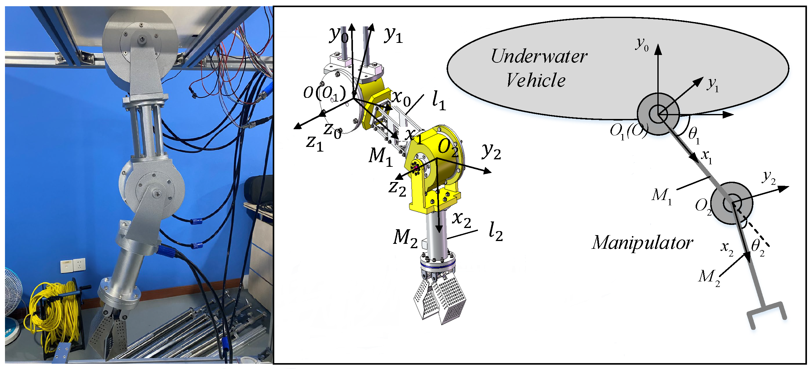
Section 5, with the help of an own -developed underwater manipulator, which is shown in
Figure 1, the effectiveness of the control method (TDE-NRLSMC) proposed in this paper is verified by experiments.
3. Controller Design
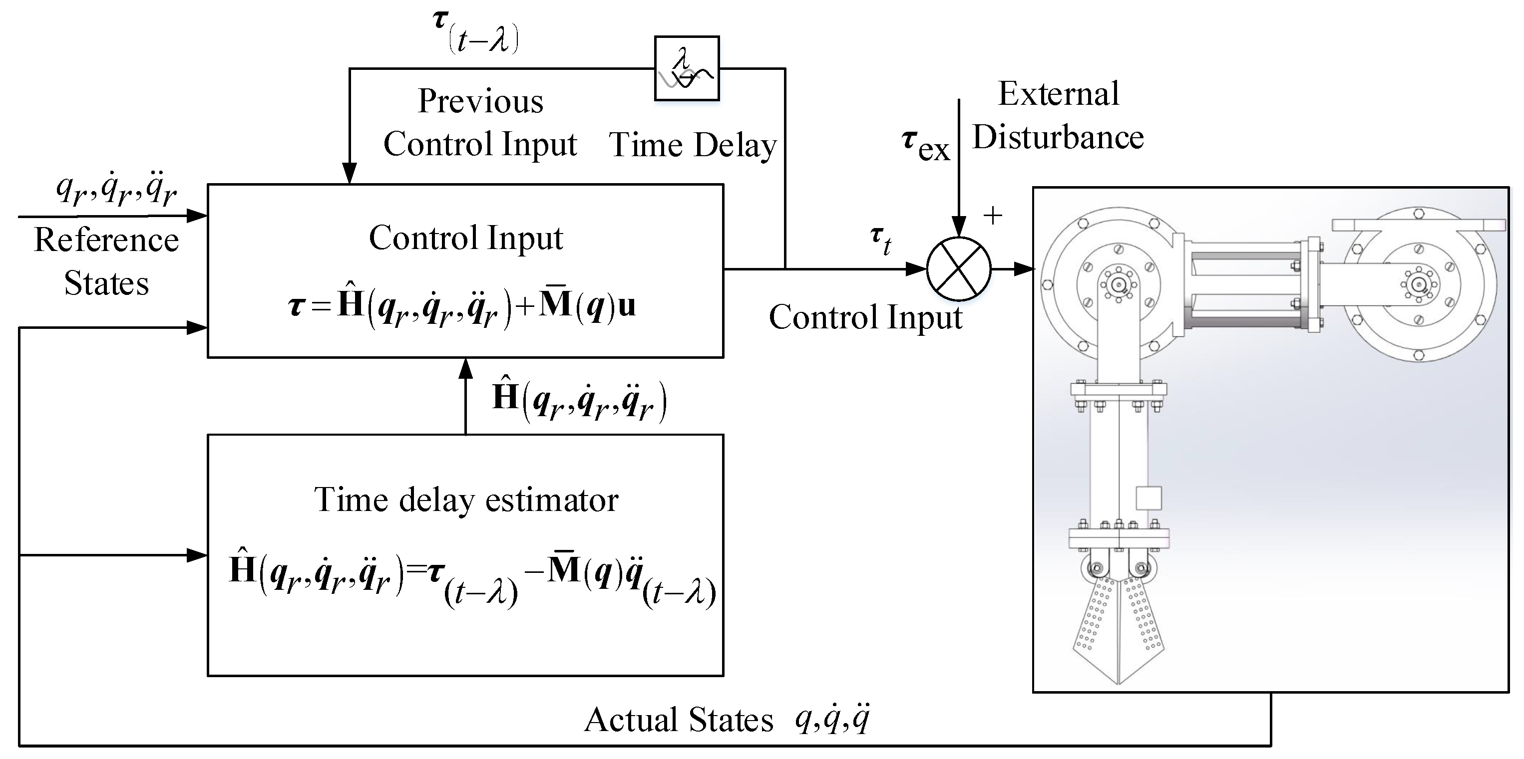
In order to reduce the reaching time in the process of trajectory tracking control, eliminate system chattering, and reduce the influence caused by system uncertainties and time-varying external disturbances, TDE-NRLSMC is presented in this section (
Figure 2).
3.1. Assumptions
This paper is grounded on the following assumptions: (1) The external disturbances acting on the underwater manipulator are bounded. (2) The reference trajectory and its derivatives , exist and are bounded.
Noting that the above assumptions are readily satisfied in practical operational scenarios. In real underwater environments, the disturbances caused by water currents are typically bounded. Meanwhile, the reference trajectories are typically designed by humans and satisfy the condition of having existing and bounded derivatives for the reference trajectories.
3.2. Design of Manipulator Trajectory Tracking Controller of TDE-SMC
By adopting TDE, Equation (
1) can be rewritten as follows:
where
is a constant diagonal matrix to be designed and
is referred to as a lumped unknown dynamic vector of the manipulator.
Define the reference trajectory of the manipulator as
, which is continuous and differentiable. Then, the trajectory tracking error
and the change rate of the trajectory tracking error
can be defined in the following forms, respectively:
Define the sliding mode surface vector
as follows:
where
is the system sliding surface parameter matrix, which is positive definite such that
.
With the sliding manifold mode surface vector defined as Equations (
4), (
9) and (
10), a proposed TDE-SMC controller is designed as follows:
where
is the reaching law of SMC to be designed,
k is the gain factor,
stands for the estimation of
in Equation (
2), and
is the gain factor.
By adopting TDE,
can be obtained as expressed in [
25] as follows:
where
denotes a time-delayed value, which is usually chosen as several sampling periods.
Finally, combining Equations (
5)–(
7), the TDE-NRLSMC controller is governed by adopting a general reaching law of SMC
as the reaching law, the TDE-SMC controller is governed by the following:
3.3. Switching Reaching Law for Improving Sliding Mode Control
In order to reduce the oscillation of inputs, the reaching law of SMC is established using Equation [
26]:
where
,
,
is a hyperbolic tangent function, and
is defined as follows
where
,
and
is the length of the interval of the special power function
between the positive and negative symmetric linear segments around the origin.
And, the TDE-NRLSMC controller is governed by the following equation:
3.4. Stability Analysis of TDE-NRLSMC
In this section, the stability of TDE-NRLSMC is analyzed in two steps. A connection was established between the time delay estimation error and the tracking error of the underwater manipulator. Then, the uniform asymptotic boundedness of the tracking errors for the underwater manipulator was demonstrated, thereby confirming the stability inherent in the control approach put forth.
Step 1. Prove the convergence of the tracking error.
Substituting Equations (
5), (
9) and (
11) into Equation (
2) yields:
where
is the TDE error.
The Lyapunov function of the control system is defined as follows:
Combining Equations (
9), (
10), and (
14),
can be rewritten in the following form:
When , , , and , then . And, when , , , and , then . So, .
Combining Equations (
9) and (
13),
can be rewritten in the following form:
where
and
are derivatives of
and
. If
is bounded (the boundedness of
will be discussed in Step 2),
is bounded. According to Equation (
9),
is bounded. And,
,
,
, and
are all bounded, so
is bounded. What is more,
is negative semi-definite (
). Then, according to Barbalat’s lemma [
27],
as
.
So, when , then , , and the stability of the control system is assured.
Step 2. For
to be bounded, the following condition must be satisfied [
28]:
where
stands for the
ith eigenvalue and
is an
identity matrix.
It has been proved in the existing work [
28] that Equation (
17) can be easily satisfied by the suitable choice of
. Therefore, when Equation (
17) is properly satisfied,
is bounded, and the stability of the control system is assured.
4. Simulation Studies
4.1. Simulation Model
In this section, to illustrate the effectiveness of the proposed TDE-NRLSMC method, comparative simulations in the presence of small environmental disturbances have been performed on an own-developed manipulator. The D-H parameters of the manipulator are listed in
Table 1. And, the basic physical parameters of the underwater manipulator are shown in
Table 2.
4.2. Simulation without External Disturbances
To clearly demonstrate the effect of the proposed algorithm on chattering suppression, a comparative simulation was conducted between the proposed algorithm (TDE-NRLSMC) and TDE-SMC under conditions of no external disturbances. The underwater manipulator is ordered to track a fixed desired position of and .
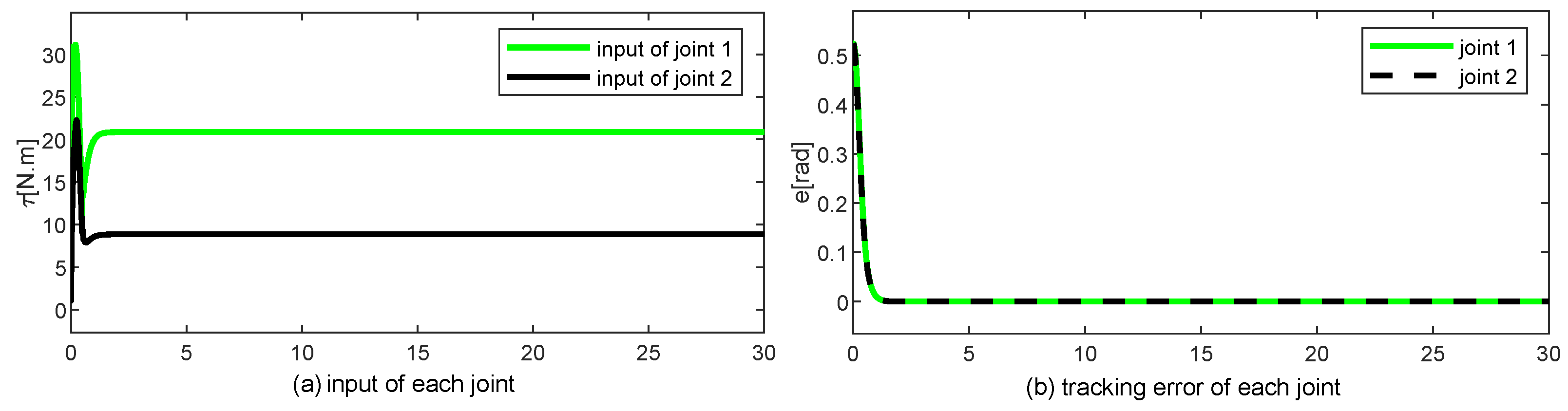
The results are displayed in
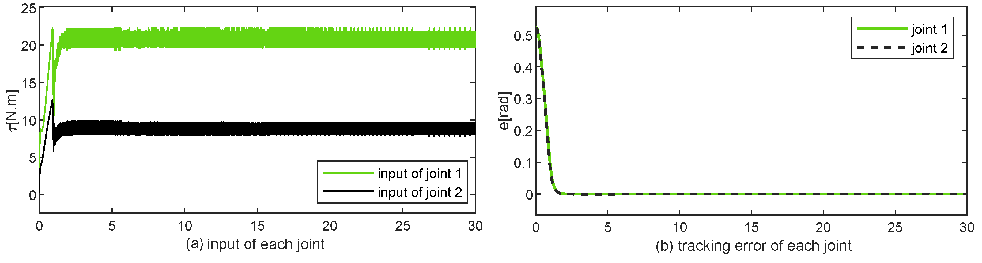
Figure 3 and
Figure 4, with the parameters
and
. The simulation results indicate that both TDE-NRLSMC and TDE-SMC are capable of controlling the joints to track the desired trajectories. However, the control input of TDE-SMC exhibits pronounced oscillations between 19.28 N·m and 22.36 N·m once the system reaches a stable state, whereas the control input of TDE-NRLSMC remains smooth and continuous post-stabilization.
4.3. Simulation with External Disturbances
To simulate the manipulator in a wave environment, it is necessary to establish the external environment disturbance model for the underwater manipulator. The environmental disturbances of the manipulator mainly come from the effects of waves. And, according to [
29], the torque applied by the waves can be written as follows:
where,
is the length of each link,
is the density of fluid,
is the drag coefficient,
is the diameter,
is the added mass, and
w is the circular frequency of the waves.
Additionally,
and
in Equation (
18) can be written as follows:
where
is the frequency of encounter,
,
N is the equally spaced frequency bands,
is the number of waves,
is the random phase shifts relative to each frequency, and
is the wave spectrum function of the
ith encounter wave.
Considering the effects of system uncertainties, we introduced the modeling uncertainty parameters in simulations, which are designed as follows [
30]:
,
,
,
. The initial position vectors of joint 1 and joint 2 are
rad,
, and the sampling time
s. And, the entire simulation process takes the time of 30 s.
The selection of the design parameters
,
,
, and
l, which are associated with TDE-NRLSMC, depends on the time that the manipulator spends tracking the reference trajectory and the tracking accuracy. According to [
26], those design parameters that are associated with TDE-NRLSMC are designed as in
Table 3.
In the simulation of the mixed trajectory tracking, the reference trajectories of two joints of the manipulator are governed by the following equations:
The relevant parameters of NRLSMC in the simulation are set as
,
,
.
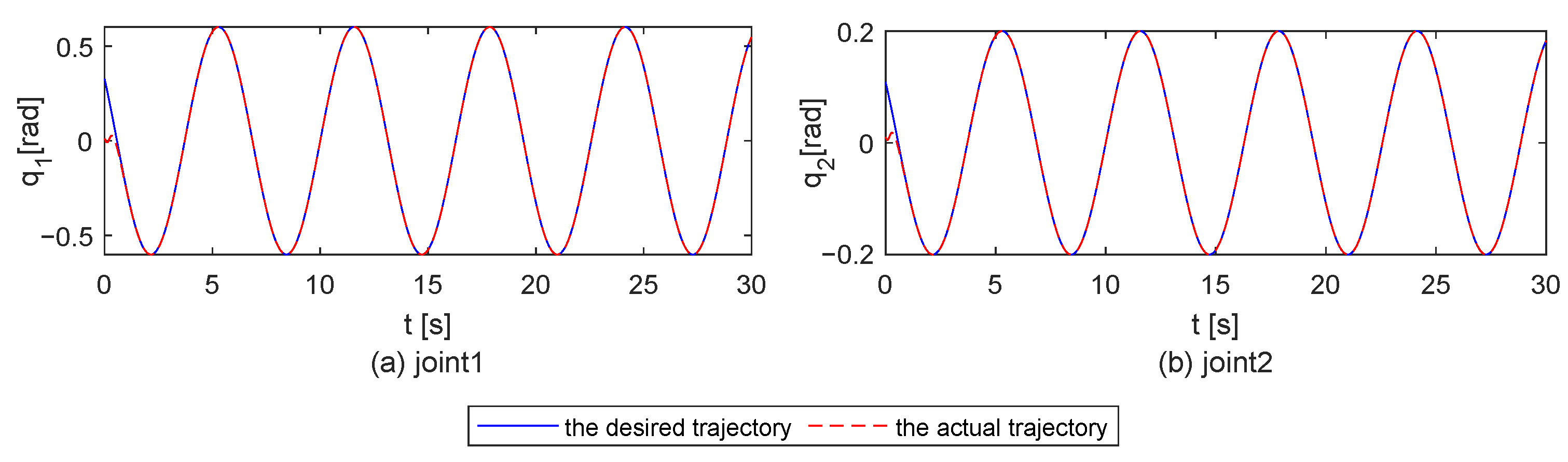
Figure 5 shows the desired trajectories and the actual trajectories of each joint based on the TDE-NRLSMC controller in the wave environment. As seen from
Figure 5, each joint of the underwater manipulator can accurately track the desired trajectory within 1 s, which reveals the effectiveness of the TDE-NRLSMC controller.
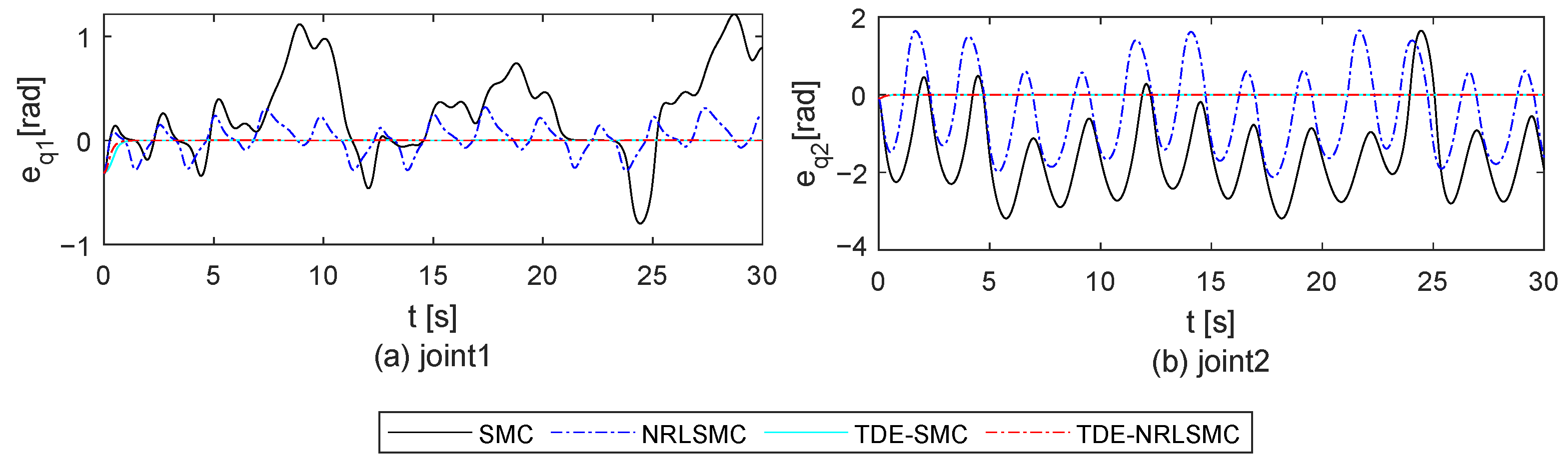
In order to illustrate the superiority of the proposed method in terms of tracking accuracy, TDE-NRLSMC is compared with other controllers, i.e., SMC, NRLSMC, and TDE-SMC. The relevant parameters of these controllers in the simulation are set as
.
Figure 6 shows the trajectory tracking errors of each joint based on the above controllers.
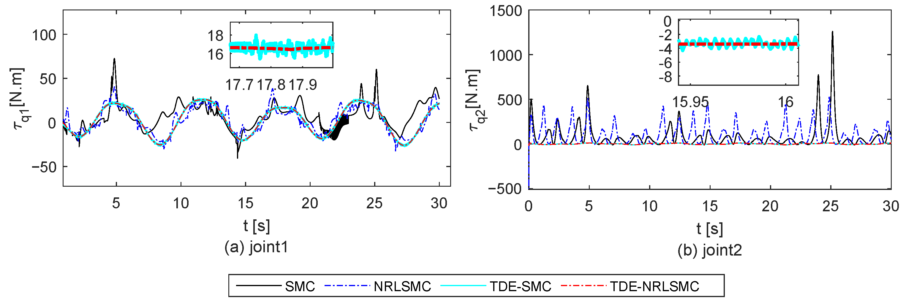
Figure 7 shows the control inputs among the different schemes.
The performance comparison between various control strategies on the response time, overshoot, and the root mean square errors (RMSEs) of SMC, NRLSMC, TDE-SMC, and TDE-NRLSMC are presented in
Table 4 and
Table 5. Anderson, an insightful quantitative assessment, was conducted on the results.
From the performance on Joint 1, the following can be seen: SMC and NRLSMC exhibit the quickest rise time at 0.27 s, while TDE-NRLSMC demonstrates the slowest rise time at 1.34 s. TDE-SMC showcases the least overshoot at 0.0001 rad, with TDE-NRLSMC following closely at 0.0002 rad, whereas SMC records the highest overshoot at 1.2120 rad. Notably, TDE-NRLSMC yields the smallest RMSE at 0.0145 rad, while NRLSMC demonstrates the largest RMSE at 0.4941 rad.
From the performance on Joint 2, the following can be seen: TDE-SMC and TDE-NRLSMC display the swiftest rise times, clocking in at 1.09 s, while SMC lags behind with a response time of 1.79 s. Impressively, TDE-NRLSMC boasts the least overshoot at 0.0001 rad and the smallest RMSE of 0.0045 rad.
The above analysis reveals that the model-free controller integrated with TDE technology significantly reduces the overshoot and trajectory tracking errors for the underwater manipulator in an environment characterized by unknown water flow disturbances. Moreover, TDE-NRLSMC exhibits the smallest RMSE across both joints, highlighting the superiority of the proposed controller in comparison to other counterparts.
It is obvious that in both disturbance-free and disturbed environments, TDE-NRLSMC demonstrates the capability to maintain the stable tracking of the desired trajectory for the joints of the underwater manipulator. It also effectively suppresses chattering. Such results validate the suitability of the proposed method for sensitive systems such as underwater manipulators.
5. Experiments
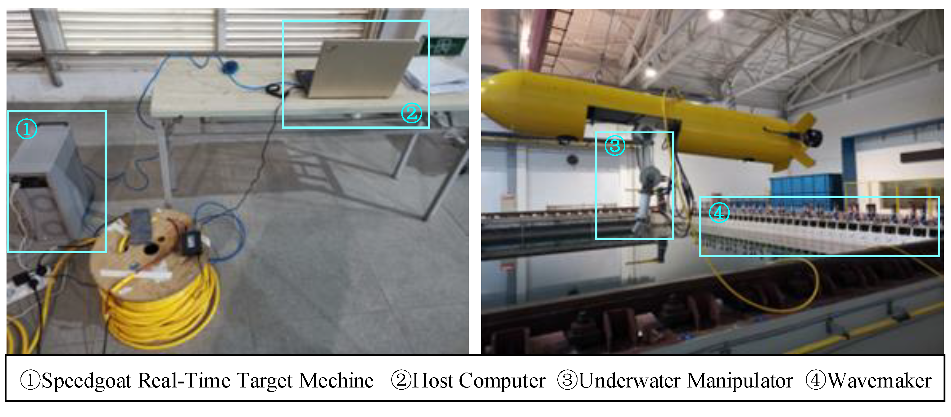
To comprehensively validate the efficacy of the proposed control methodology, trajectory tracking experiments were conducted on a manipulator integrated into an own-developed underwater vehicle manipulator system (UVMS), as shown in
Figure 8.
The experimental setup takes place in a controlled pool environment featuring a wavemaker, which is utilized to generate waves with the desired frequency and wave height, simulating the disturbances induced by fluid flow during the operation of the underwater manipulator. This approach enabled the creation of controlled and reproducible wave conditions, facilitating precise assessments of the controller’s performance under wave-induced disturbances.
Under normal circumstances, the underwater manipulator’s operating scenario involves the equipped vehicle hovering in the water, subject to continuous swaying induced by external disturbances, such as waves. To rigorously evaluate the impact of the proposed controller on the manipulator’s operational performance in environments that closely resemble real-world operational scenarios, the vehicle is tethered in the water using a rope throughout the experiment. In this approach, the complete UVMS is immobilized while retaining the swaying motion induced by the vehicle as the manipulator operates. This setup facilitates a more comprehensive evaluation of the robustness of the controllers by taking into account the influence of the vehicle’s swaying motion during the assessment process.
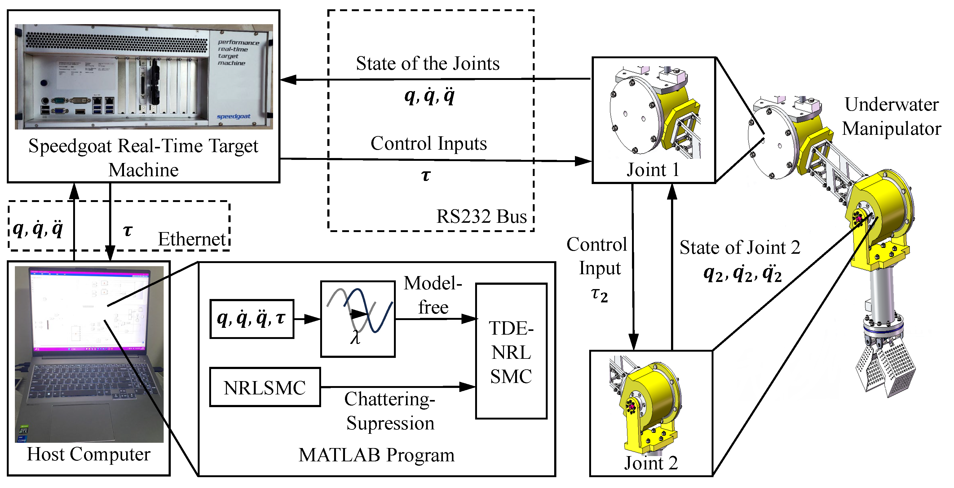
The experimental platform of trajectory tracking, which is shown in
Figure 8, consists of a rectangular experimental pool, a
Speedgoat Real-Time Target Machine, and the manipulator. The rectangular pool is 300 m long, 16 m wide, and 7.5 m deep. The waves generated by the wavemaker are level two waves, which have a height of 0.2 m and a peak frequency of 1.5 Hz.
The control of the joint motors and the feedback of the actual motor angle position of the underwater manipulator are achieved through the
Speedgoat Real-Time Target Machine. The framework of the experimental platform is illustrated in
Figure 9.
In order to improve the tracking accuracy in the experiments, we utilized the Speedgoat Real-Time Target Machine to dynamically translate the MATLAB program into an executable file and generate control signals in real time. Additionally, communication between the host computer and the Speedgoat Real-Time Target Machine is established via Ethernet, facilitating swift signal transmission and thereby enhancing the real-time performance of the controller.
The experiment utilized a Lenovo Thinkpad E460 as the host computer, with an Intel Core i5 6500 2.5 GHz and 8 GB of RAM. The host computer runs a MATLAB/Simulink real-time program, employing fixed step-size discretization, and establishes communication with the Speedgoat Real-time Target Machine via Ethernet. The real-time target machine and the underwater manipulator system communicate through an RS232 bus, operating at a baud rate of 9600 bps. The Speedgoat Real-time Target Machine translates the MATLAB program into an executable file and outputs control signals. Then, the underwater manipulator system receives those signals and delivers feedback regarding the states of the two joints via an RS232 bus, functioning at a baud rate of 9600 bps.
The actual joint angles of the underwater manipulator are obtained through angular sensors. To effectively validate the performance of the proposed controller, the parameter settings of the controllers, as well as the desired trajectories of the joints, are kept identical to those used in the simulation.
In order to verify the superiority of the proposed method in practice, TDE-NRLSMC is compared with SMC, NRLSMC, and TDE-SMC.
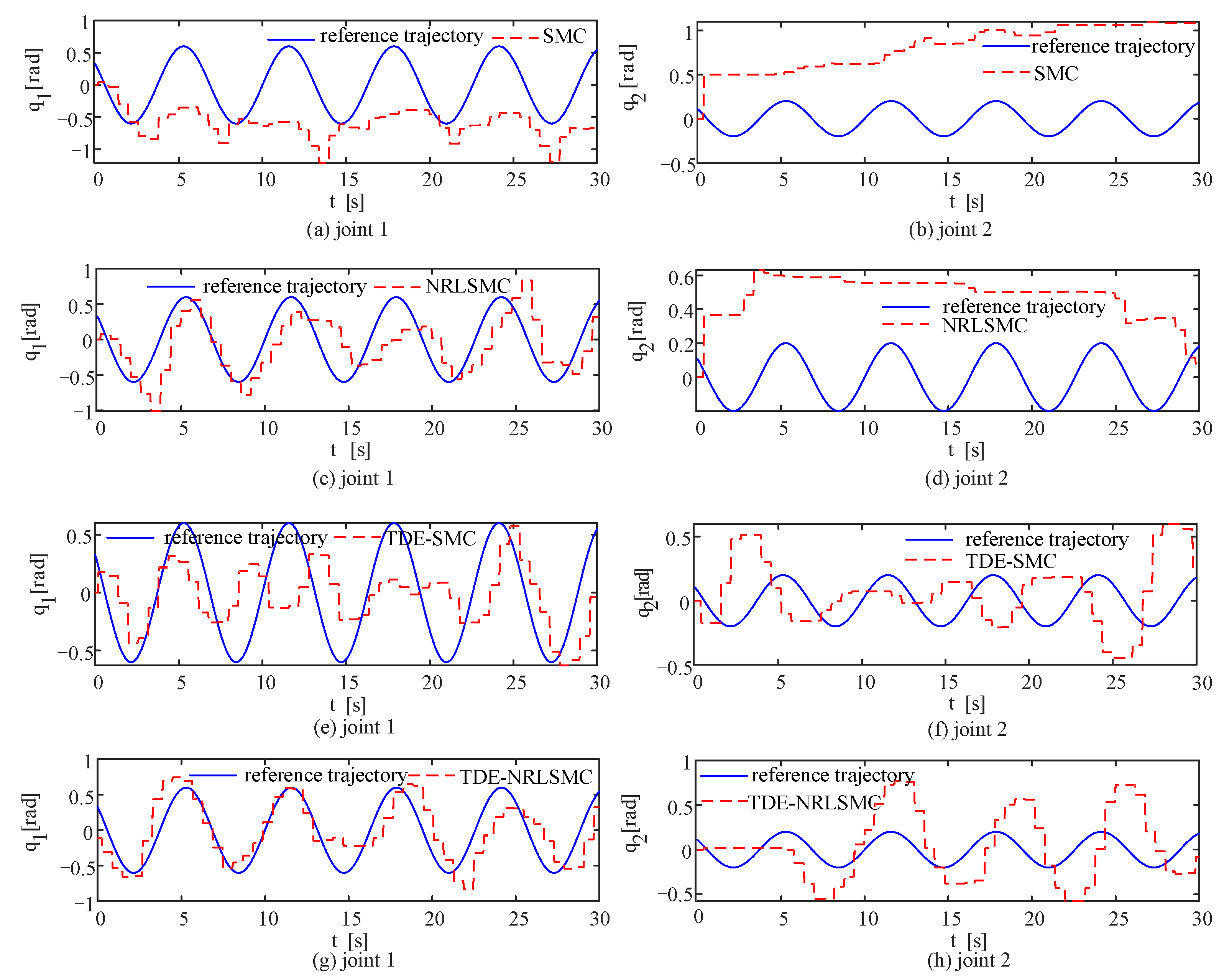
After the noise elimination of the experimental data,
Figure 10 shows the real trajectories and reference trajectories of two joints based on different controllers in the wave environment. And, the root mean square errors of the tracking errors based on the different schemes are listed in
Table 6.
It can be seen from
Figure 10 and
Table 6 that, among all the controllers, SMC exhibits the maximum RMSE values of 0.6934 rad and 0.8681 rad, respectively. For Joint 1, TDE-NRLSMC achieves the lowest RMSE of 0.299 rad, while for Joint 2, TDE-SMC demonstrates the smallest RMSE of 0.33 rad. This highlights that when facing substantial disturbances, the controllers incorporating the TDE element outperform their counterparts without the TDE element. Furthermore, the average RMSE of each joint for RDE-NRLSMC is the lowest among all the controllers at 0.3393 rad. This represents a reduction of 57%, 25%, and 8% compared to SMC, NRLSMC, and TDE-SMC, respectively. The above experimental results illustrate the superiority of the proposed controller over other controllers in a water environment with wave disturbances.
6. Conclusions
In this study, a novel approach to controlling underwater manipulators that eliminates the need for precise mathematical models is proposed. By utilizing pre-designed matrices and incorporating control inputs from the previous time step, this method estimates the states of the system, thereby addressing the challenges associated with accurately modeling the manipulator’s behavior in environments featuring uncertain water flow disturbances. Furthermore, this method integrates a time-delay estimator with sliding mode control, demonstrating robustness against unpredictable water flow disturbances and ensuring optimal performance of the underwater manipulator in demanding aquatic conditions. The introduced controller employs a uniquely designed sliding mode reaching law, effectively minimizing controller oscillations. Through simulations, the proposed approach was evaluated by subjecting it to underwater manipulator models with model uncertainties. We also conducted comparative assessments in environments characterized by sinusoidal disturbances, revealing the robustness of the proposed controller against underwater flow disturbances and model uncertainties. Moreover, practical underwater experiments were carried out in a pool equipped with a wave generator, effectively validating the precision control capabilities of the controller in real-world underwater scenarios, all without necessitating an exact mathematical model. The proposed control methodology primarily finds application in underwater manipulators mounted on underwater robots operating in unfamiliar aquatic environments. The proposed method enables the precise control of the underwater manipulator without relying on an accurate mathematical model, facilitating task execution in water bodies with unknown flow conditions. However, given the diverse and unpredictable nature of underwater operational tasks, the standalone capability of an individual underwater manipulator is inherently limited. Therefore, future efforts will emphasize the development of collaborative control strategies for multiple manipulators to address these challenges.


