Article

Bearing Characteristics of Tripod Bucket Foundation under Horizontal and Moment Load in Sand

1
Key Laboratory of Concrete and Prestressed Concrete Structure of Ministry of Education, Southeast University, Nanjing 210096, China
2
Department of Industrial Design, Monash University, Melbourne 3800, Australia
3
Fujian Yongfu Power Engineering Co., Ltd., Fuzhou 350001, China
*
Author to whom correspondence should be addressed.
J. Mar. Sci. Eng. 2023, 11(8), 1631; https://doi.org/10.3390/jmse11081631
Submission received: 27 July 2023 / Revised: 17 August 2023 / Accepted: 19 August 2023 / Published: 21 August 2023
(This article belongs to the Special Issue Engineering Properties of Marine Soils and Offshore Foundations)

Abstract

:
Based on a series of physical model tests and numerical simulations, the bearing characteristics of a tripod-bucket foundation are investigated. It is found that with the decrease in aspect ratio (L/D), the rotation center of the foundation will decrease, and the displacement model change from rotation to uplift. Characteristics of earth pressure on the buckets from both finite element analysis and model tests are studied, which is used to explain the failure mechanism for tripod-bucket foundations with different L/D. A revised method is proposed to estimate the moment bearing capacity of the tripod bucket foundation under horizontal and moment load. This method is thought to be more convenient and applicable in the practice.

1. Introduction

Offshore wind energy has been developing rapidly in recent years as a clean and sustainable energy resource [1,2]. However, the construction expense, especially the cost of the foundation, negatively affects the cost-effectiveness of offshore wind farms. The bucket foundation, which is installed by self-weight and suction pressure, is a good option for the offshore wind turbine foundation nowadays [3]. It is thought to be a cost-effective foundation type due to the speed of installation and reduction in material costs compared with other commonly used foundations. At present, tetrapod, tripod and single buckets are common types of bucket foundations. The tripod bucket foundation is made of three single buckets placed in a triangular shape and is thought to be more suitable for coastal areas with water depths greater than 20 m [4].
In the offshore environment, wind turbine foundations are subject to horizontal load (H) and the moment load (M) generated by wind, waves and currents [5,6,7,8]. Compared with offshore oil and gas platforms, the vertical load (V) from a wind turbine is relatively low [9]. Therefore, the combined HM loads are critical for the foundation of offshore wind turbines [10,11]. To ensure safe operation and good serviceability of the wind turbines, the bearing characteristics of the tripod bucket foundation under combined horizontal load and moment load should be studied comprehensively.
A number of investigations into bearing capacity focusing on single bucket foundations [12,13,14,15,16,17,18] have been conducted. However, group effects on the bearing capacity of multiple foundations in sand are still not enough. Martin and Hazell [19] investigated the group effect of strip foundations in non-homogeneous clays and found that the interaction of the footings was beneficial for improving the vertical bearing capacity coefficient. Gourvenec and Jensen [20] conducted an in-depth analysis of the effect of barrel spacing (S) on the bearing capacity of the foundation, and the group effect of two pile group systems with an aspect ratio L/D (L is the embedment depth and D is the diameter) of 0.5 in uniform clay was explored. It is found that with the increase in foundation spacing and embedding depth, the combined bearing capacity of HM loads increased significantly.
Bang et al. [21] conducted a series of centrifuge model tests. A three-dimensional analytical solution to evaluate the effect of the loading depth on the ultimate horizontal bearing capacity of suction piles was proposed. The results show that the location of the applied load influenced the modes of movement. When the loading depth increases, the ultimate horizontal bearing capacity of the suction piles would increase.
There are also some empirical formulae of bearing capacity proposed by theoretical analysis or numerical simulation. Based on the upper limit theory, Zhao et al. [22] found three critical positions S1, S2 and S3 which have significant effects on the horizontal bearing capacity of the quadruple bucket foundation. Considering the influence of the load direction on the bearing capacity, the empirical formula of the relationship between the distance among piles, the load direction, and the horizontal bearing capacity was established. Kim and Oh [23] studied the group effect of a tripod bucket foundation in cohesive soil with a three-dimensional finite element method, and the efficiency coefficient was proposed. The results show that the group efficiency factor had little effect on the vertical bearing capacity with S/D > 1.5, whereas the factor of the horizontal and the moment capacity of the tripod bucket foundation tended to be larger. Compared with previous studies, Hung and Kim [24] proposed new equations to evaluate the vertical-, horizontal- and moment-bearing capacities of the bucket foundation considering the effects of the non-homogeneity of clay and embedment depth. The capacity envelopes under general combined loads were defined. Based on the finite element method, He et al. [25] simulated the bucket penetration in clay by reducing the friction factor between the bucket wall and the surrounding soil. The results indicated that the spacing between buckets was a key factor affecting the bearing capacity of the tripod bucket foundation, but its bearing capacity envelope was similar to the monopod bucket foundation.
Previous studies have shown that the bearing characteristics of foundations are significantly influenced by aspect ratios L/D [15], load location [21], load direction [22], spacing ratios S/D and group effects [19,23]. Additionally, most of the work focuses on the mechanical properties of the single bucket foundation or the mechanical properties of the bucket foundation in clay. However, the research on the mechanical properties of the tripod bucket foundation in sandy soil is not enough. There is little comparison and analysis between numerical simulation results and experimental results now. This study aims to analyze the effect of bucket spacing and aspect ratios on the bearing capacity of the tripod bucket foundation under the combined load of HM based on a physical model test and three-dimensional finite element analysis.

2. Materials and Methods

2.1. Physical Model Test

A series of model tests were performed. Common sand was used in this study. Particle size distribution tests were conducted which showed it to be medium sand. Based on the relative porosity ratio measured on site, the relative density of the sand used in this experiment was 0.59, which was classified as medium-dense sand. The physical properties of the sand used in the model test are shown in Table 1. The tests were conducted in a model box with size of 1 m × 1 m × 1.2 m (length × width × height). Single-side drainage was adopted and pebbles, drainage pipe network and geotextile were laid at the bottom of the model box. The sandy soil was laid in the model box layer by layer and manual compaction was adopted to meet the test requirements. After the sand was laid, it was filled with water and allowed to stand for 3 days for consolidation. Q235 steel pipe was used as the bucket model because the deformation of the foundation was ignored in the test. The parameters of steel piles are shown in Table 1. To ensure the same model bucket weight and meet the requirements for eliminating the boundary effect of the model box [26], model sizes are calculated as shown in Table 2. The final distribution of the outer diameter of the bucket is 102 mm, 120 mm, 133 mm and the bucket length is 164.7 mm, 134 mm, and 112.6 mm, respectively, which is consistent with the range of aspect ratio of suction bucket foundation in practical engineering. Lifting lugs were set every 90 mm from the bottom of the tripod to apply horizontal load to the model as shown in Figure 1.
Two bolt holes were set at the top of a single bucket model. One was used to connect with the tripod at the top of the model, and the other was used as an exhaust hole to facilitate the penetration and extraction of the bucket model. Earth pressure cells were placed symmetrically at 1/3 L and 2/3 L from the foundation top at the outside, as shown in Figure 2.
When loading, ten steps were used with a load level difference of 1/10 of the estimated bearing capacity by adding weight blocks. Each level of loading was maintained for at least 5 min until the displacement remained almost stable. Both the earth pressure and displacement were measured and recorded to analyze the failure phenomenon and mechanism of the tripod bucket foundation in sand.

2.2. Numerical Simulation

The 3D Finite Element (FE) analyses were conducted with an elasto-plastic model and Mohr–Coulomb failure criterion. In practical engineering, the stiffness of the bucket is much higher than that of the soil, and it can be considered as a rigid foundation. This test does not consider the deformation of the bucket body under load but only considers the deformation between the bucket and the soil and the soil failure. The bucket foundation in the numerical simulation was modeled as a rigid body, and the parameters of the bucket foundation were shown in Table 2. The normally consolidated sand under drained conditions was modeled with the basic parameter same with the physical model test shown in Table 1. Brinkgreve et al. [27] confirmed that setting a small cohesion force and dilatancy angle was beneficial to improve the accuracy of the calculation. Young’s modulus Es of the sand was set as 38.6 Mpa. The interface coefficient between the bucket and soil was set at 0.68, with the aim of increasing the flexibility of finite element mesh, reducing the sharp angle of strength reduction and avoiding non-physical stress results.
Figure 3 shows the arrangement of the tripod bucket foundation and boundary extensions adopted in this study. The size of the soil elements gradually increased from the bucket to the domain boundary. The soil was divided by a dense grid within a horizontal range of 3 S (three times the spacing between buckets) and a vertical range of 2 L (two times the length of the bucket) boundary, and the roughness coefficient is 0.35. The remaining parts of the soil were adaptively divided by software. The boundary with horizontal boundary extents of the bucket foundation model was 10 S and the vertical was 5 L, respectively, which was thought to be able to eliminate the boundary effects.
The connection between the individual bucket foundations as jacket structure in practice was numerically and rigidly simulated by using a Load Reference Point (LRP) at the top center of the triangle cross in this study [20,24,28]. The load was applied to LRP using the load-controlled method, which increased 1/10 of the estimated ultimate bearing capacity at every step. When the load-controlled method is used in the physical model experiment, the long interval between each stage of loading belongs to slow-loading. The sand has good permeability and sufficient time for drainage, so it is defined as drainage behavior. The ultimate bearing capacity was estimated according to the load-displacement curve. The bearing capacity was determined by the tangent intersection method or the phenomenon of pulling out [29].

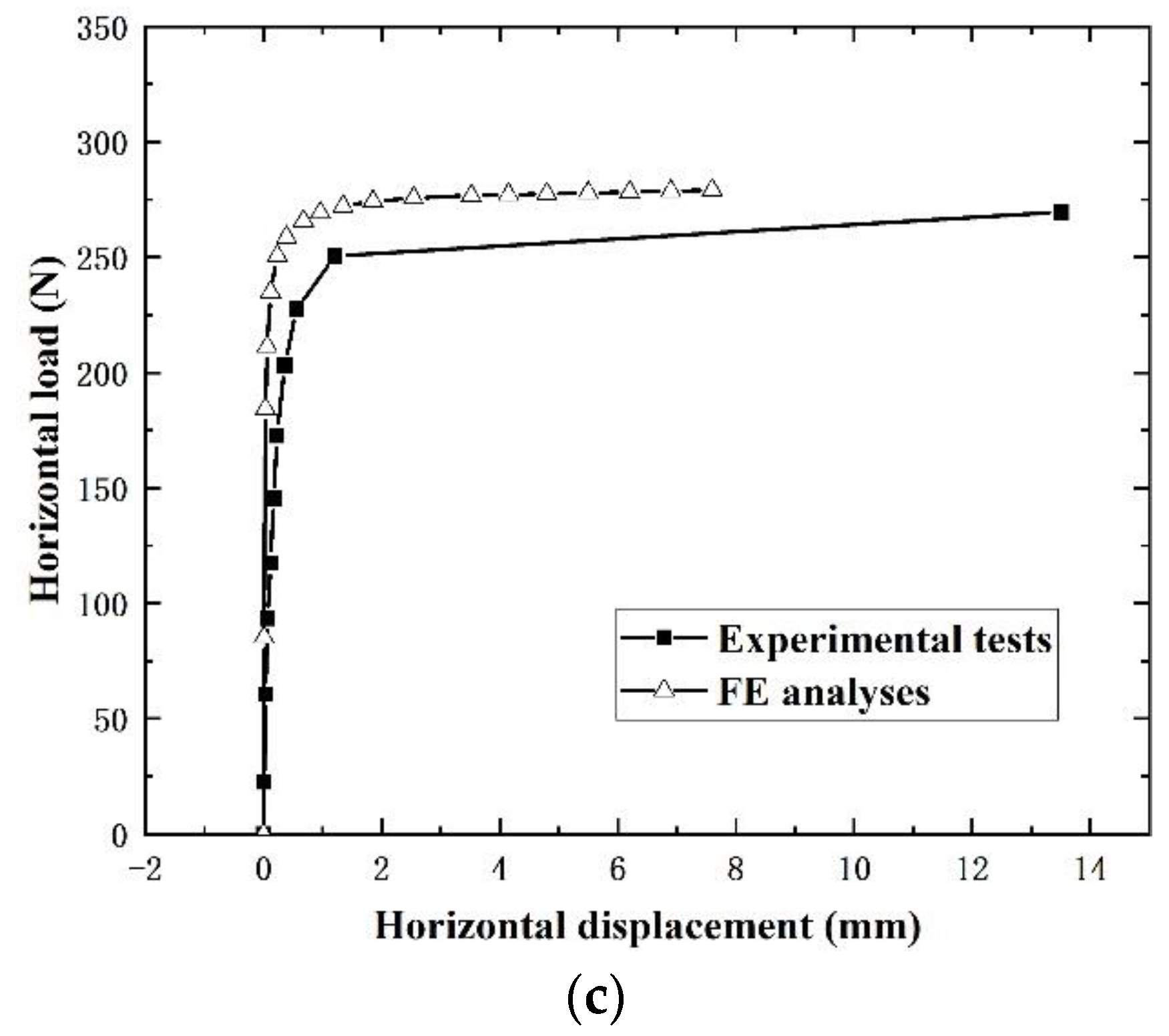
2.3. Validation of Numerical Modeling

The numerical modeling adopted in this study was validated by the results from the physical model tests. Figure 4 shows comparisons of the horizontal bearing capacities from model tests and FE analysis with S/D = 3 and L/D = 1.61, 1.12 and 0.85, respectively. The maximum error may be caused by the longer load interval. Based on this validation, the numerical modeling adopted in this study was thought to be reliable to evaluate the bearing capacity of the tripod bucket foundation in sand.

3. Results

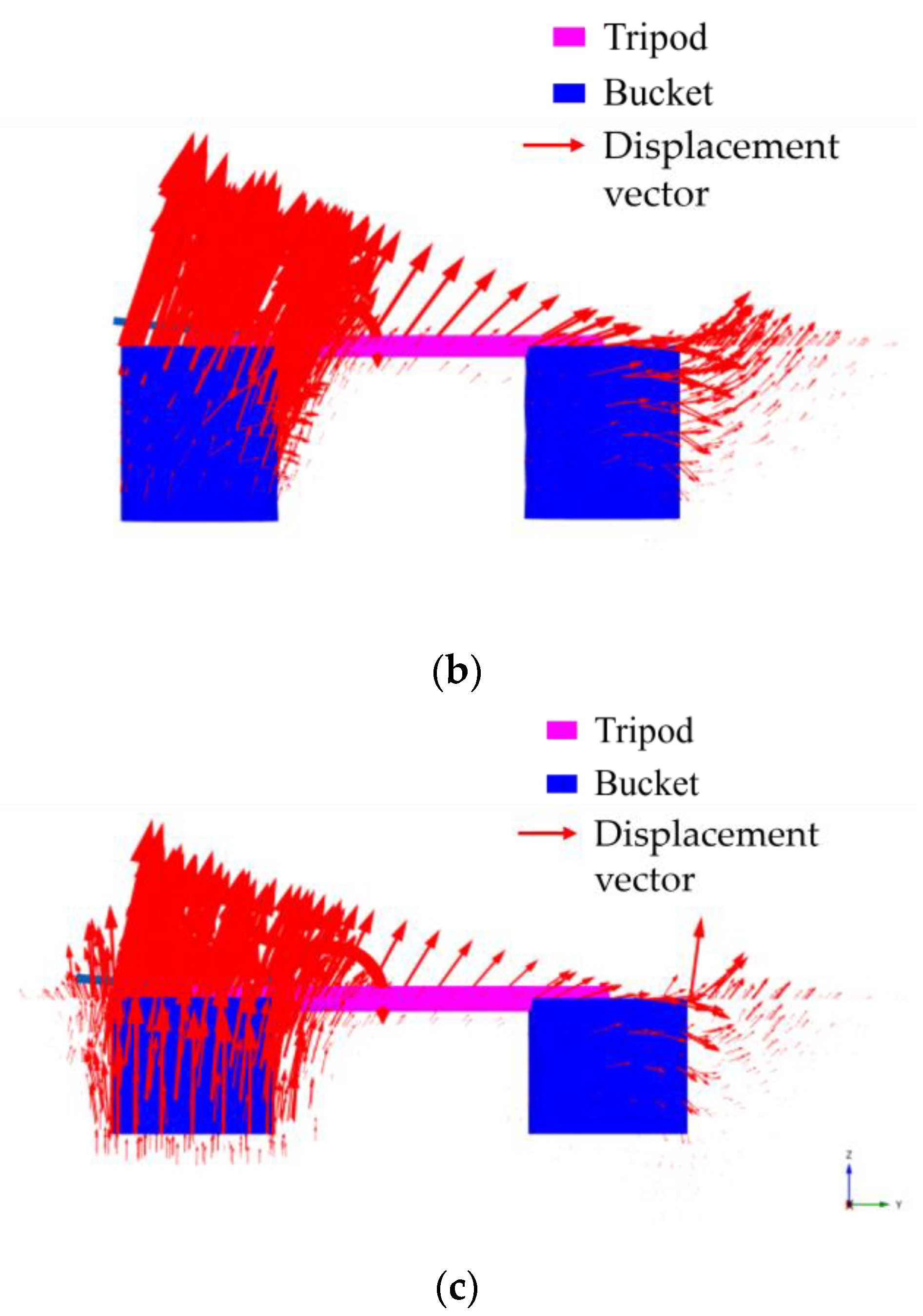
3.1. Failure Mechanism under H–M Loadings

According to the model tests, the failure process of the tripod bucket foundation can be divided into three stages, the initial stage, the intermediate stage and the failure stage.
In the initial stage, the horizontal displacement was very small and the soil around the bucket may be in the elastic state. Only micro-cracks behind the tension bucket could be observed. At this time, there was almost no obvious deformation around the compression bucket as shown in Figure 5a. As the load increased, the soil around the bucket gradually came to the plastic state. The cracks behind the tension bucket gradually expanded to a larger region at the rear side, and soil rise could be observed at the front side of the tension bucket. At this time, the tension bucket tended to pull up and rotate in the loading direction. Also, the cracks and soil deformation around the compression bucket were smaller than those around the tension bucket as seen in Figure 5b.
When the load increased to a certain value, the horizontal displacement of the bucket foundation started to increase dramatically. The soil in front of the compression bucket gradually rose to form a passive failure wedge. The foundation came to the state of complete instability, as shown in Figure 5c. The plastic failure area of the compression bucket had a wider scope, so the earth pressure in front of the compression bucket may provide greater horizontal resistance of the tripod bucket foundation. When the tension bucket was pulled up, it was observed that the soil plug fell off, as seen in Figure 5d, and the plastic failure area of the soil at the front and rear sides of the tension bucket was found to be limited to the layer close to the soil surface. It could be thought that the horizontal resistance provided by the tension bucket mainly came from the friction between the bucket wall and the sand.
According to the displacement vector diagram from FE analysis (Figure 6), with the decrease in L/D, the vertical uplift movement of the tension bucket was more obvious. This was consistent with the phenomenon observed in the model test that the soil layer of plastic failure was thinner; meanwhile, with the increase in the L/D (L/D = 1.61 compared to L/D = 1.12 and L/D = 0.85), the rotation trend of the compression bucket was more obvious and the tension bucket was also accompanied by the forward tilt rotation in the process of pulling up as shown in Figure 6.
In addition, according to the displacement analyses, the rotation center of the tripod bucket foundation was not located at the central axis of the compression bucket but deviated to the horizontal force direction. The specific results are shown in Table 3. It shows that with the decrease in L/D, the distance between the rotation center and axis changes only a little and the vertical position of the rotation center became deeper. This phenomenon may well explain that the main displacement of the tripod bucket foundation with a large aspect ratio was rotation and that with a small aspect ratio was horizontal displacement.

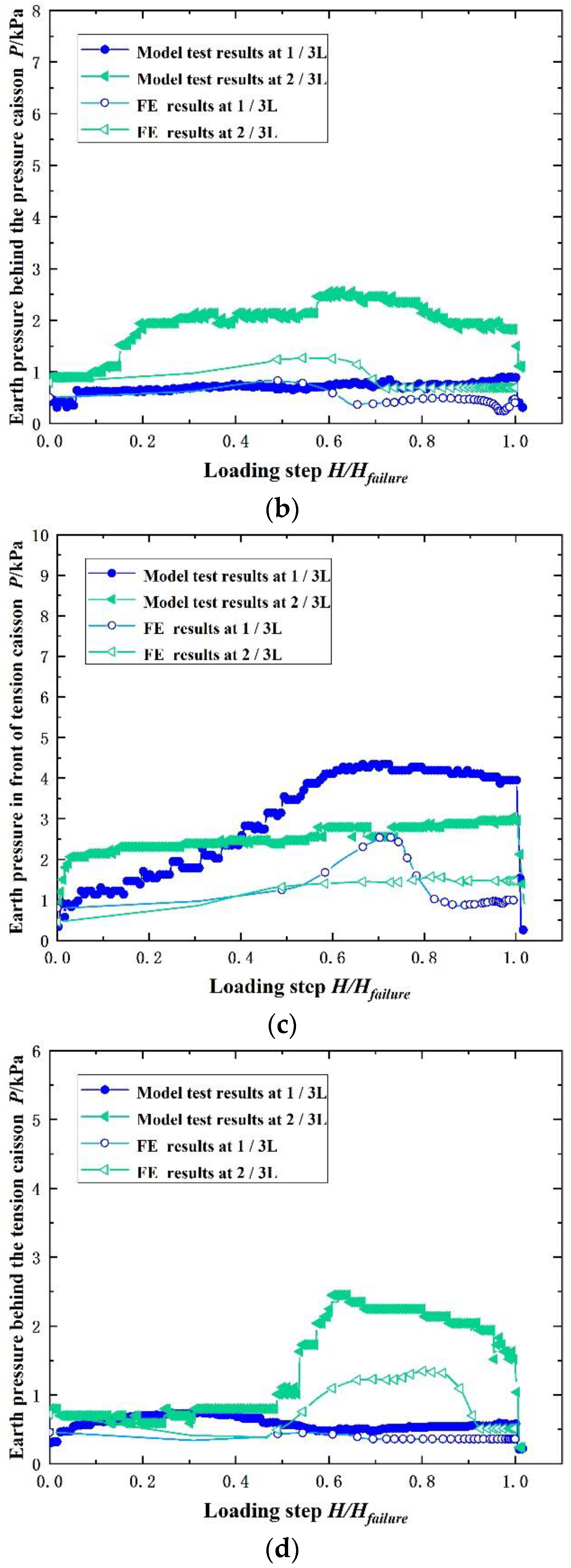
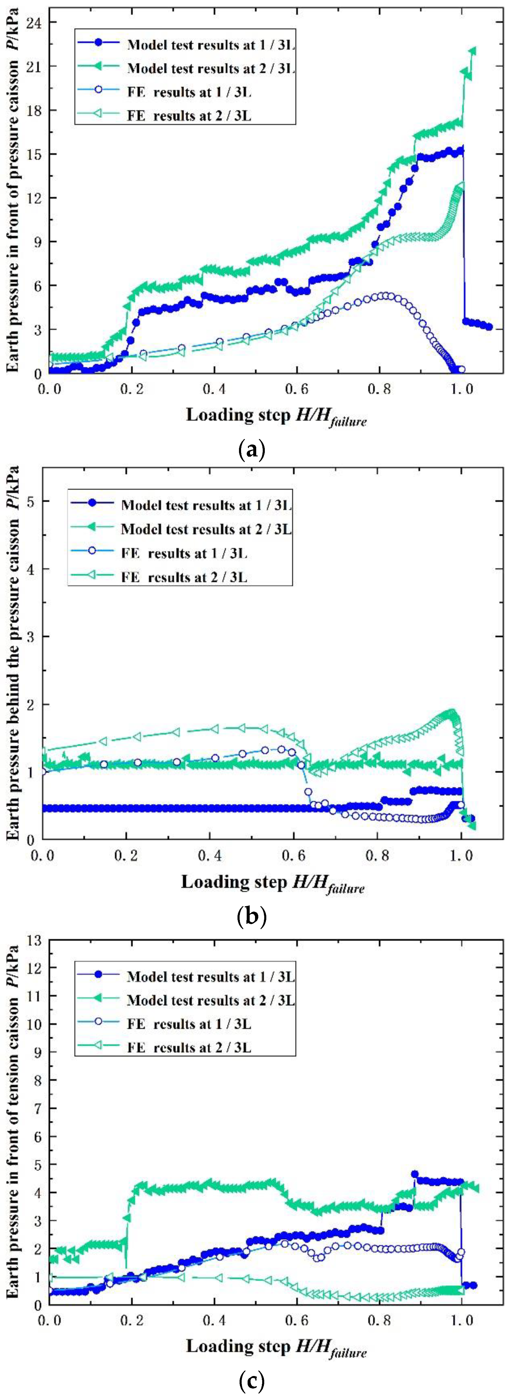
3.2. Earth Pressure Analysis

In the model tests, the horizontal earth pressure was measured by the earth pressure cell placed in the contact surface between the outer side of the bucket model and the sand as shown in Figure 2. Figure 7, Figure 8 and Figure 9 show the comparison results of soil pressure by model tests and FE analysis under the condition of L/D = 1.61, 0.85 and 1.12. According to the analyses of earth pressure, the failure mechanism of the tripod bucket foundation in the sand under the action of the horizontal and the bending moment can be further clarified.
Figure 7a shows that the earth pressure in front of the compression bucket at 1/3 L from the top of the bucket increased continuously with the increase in the horizontal load, while the earth pressure at 2/3 L increased in the initial stage and decreased in the later stage. The reason was that the tripod bucket foundation would overturn and rotate under HM and the rotation center was below 2/3 L from the top of the bucket as shown in Table 3. Therefore, the soil at 1/3 L and 2/3 L in the front of the bucket was squeezed which resulted in the passive earth pressure. As the load increased, the rotation trend was more obvious, so the earth pressure caused by the squeezing effect increased. However, when the applied load increased to a certain value, the earth pressure at 2/3 L began to decrease, which may be explained by the following two reasons. First, with the increase in load and deformation, the soil in front of the compression bucket changed from an elastic state to a plastic state due to the squeezing effect. Consequently, the earth pressure was cut down when the soil failed. Secondly, when the compression bucket is rotated, a void or loosen zone may be formed at the toe in front of the bucket. And the soil above (nearly 2/3 L) may fall down, which may cause the decrease in earth pressure.
Figure 7b shows the earth pressure distribution behind the compression bucket. Except for the model test at 2/3 L, the results show that the earth pressure behind the compression bucket was almost constant and small as the load increased. This indicated that the active earth pressure was sustained. When the load increased to about 0.7 of the ultimate capacity at 2/3 L in the model test, the earth pressure reduction may be caused by the separation between the earth pressure cell and soil due to the crack propagation behind the bucket.
Figure 7c shows the earth pressure results in front of the tension bucket. It can be seen that the earth pressure at 1/3 L increased first and then decreased, while the earth pressure at 2/3 L kept almost constant with slight fluctuations during the final steps. The tension bucket would rotate under HM. The upper part of the bucket (about 1/3 L) tilted forward and the lower part (about 2/3 L) tilted back away from the soil. As a result, the soil at 2/3 L was in an active earth pressure zone and earth pressure kept a smaller value. It may slip slightly after being disturbed, resulting in the final decrease in earth pressure. The soil at 1/3 L was in a passive earth pressure area. With increasing loading, the earth pressure increased gradually until shear failure finally occurred.
It was noticeable that the results from model tests dropped more sharply, which may be caused by the existence of an earth pressure cell. The earth pressure cell was close to the model bucket occupying a certain volume, so the measured values were more vulnerable to cracks with increasing displacement compared with the results from the numerical simulation.
Figure 7d shows the earth pressure results behind the tension bucket. The earth pressure at 1/3 L tended to be constant and the values were smaller, which corresponded with the explanation in Figure 7c that soil at 1/3 L was in the active earth pressure zone and soil at 2/3 L was in the passive earth pressure zone. There was no shear failure of soil in the passive area, so earth pressure continued to increase as the load increased.
In comparison with Figure 7a, earth pressure in front of the compression bucket at 2/3 L kept increasing as shown in Figure 8a. This was mainly affected by the displacement behaviors. For the bucket foundation with a smaller L/D under HM, its failure model can be compared with that of a wide shallow bucket foundation [30]. Horizontal displacement was dominant and the rotation center was located under the bottom of the bucket as shown in Table 3. The soil in front of the compression bucket was squeezed by the approximate translational motion of the bucket, which was difficult to cause sand leakage and local plastic failure.
The results in Figure 8b–d are similar to the earth pressure recorded in the test of S/D = 3 and L/D = 1.61. However, the results at 1/3 L and 2/3 L were closer, because the soil was more evenly squeezed. At the same time, the dominant horizontal displacement of the foundation was more likely to cause the separation between the earth pressure cell and soil, and so the earth pressure dropped dramatically.
Figure 9 shows the results of the earth pressure in the test of S/D = 3 and L/D = 1.12. Compared with the results in the test of S/D = 3 and L/D = 1.61, the horizontal displacement trend was more obvious. Compared with that of S/D = 3 and L/D = 0.85, the rotation trend was more obvious. The results in Figure 9a indicate that the bucket is subjected to passive earth pressure without obvious plastic failure. At the end of loading, there is a “steep change” in the earth pressure. In the model experiments, it is observed that the bucket maintains a small displacement until reaching the ultimate bearing capacity. At this moment, the tripod foundation loses stability suddenly and is pulled out. The difference between the earth pressure behind the compression bucket and the other two sets of tests is that the pressure decreases first and then increases when the loading comes to 0.6 times the ultimate capacity. The reason may be that there is a slight sliding of the soil behind the bucket. This results in a slight pressure decrease. In addition, the soil continues to compact in the later stage, thereby increasing the earth pressure. The distribution of earth pressure in front of the tension bucket is similar. However, the results behind the tension bucket are different. The earth pressure at 2/3 L from the top of the bucket begins to decrease in the later stage of loading, indicating that when the horizontal displacement is relatively large, there is a gap between the bucket wall and the soil behind it.
The size of the model used in the test was small and the volume occupied by the earth pressure cell cannot be ignored, so there were errors between the model tests and FE analysis. In fact, the bucket wall is circular arc-shaped, while the earth pressure measuring device is flat. The relatively bigger area of the measuring device may result in excessive and larger horizontal earth pressure measured. In numerical simulation, the measurement points did not take into account the size effect. So, the earth pressure measured by the big pressure measuring devices may be greater than that from the numerical simulation. If the size of the pressure measuring device can be reduced, it can be expected that the measurement results will be closer to the actual state. Basically, the trend of earth pressure distribution is the same. According to the results, the errors are acceptable.
Under HM loadings, the instability mode of the tripod bucket foundation is manifested as follows. In the early stage, the foundation has a trend of translation and rotation. The rotation trend of the foundation with a large aspect ratio is more obvious. And for a small aspect ratio, the translation trend is more obvious. However, the final form is manifested as overturning failure. The specific failure mode is manifested as one bucket under compression and the other two under tension. The rotation center of the tripod bucket foundation is located near the axis of the compression bucket, and as the aspect ratio decreases, the position of the rotation center will be lower. Due to the center of rotation being located near the compression bucket, the deformation of the soil around the compression bucket is more obvious, and the earth pressure near the compression bucket is significantly higher than in other areas.

3.3. Moment Bearing Capacity of Tripod Bucket Foundation under M-H

Based on the experimental and numerical results, the failure mechanism of the tripod bucket foundation under M-H was actually in the form of one bucket under compression and the other two buckets under tension. According to the study of the failure mechanism, the tension bucket was pulled up with a certain forward inclination mode, and the compression bucket was compressed with a rotation mode. It was difficult to calculate the moment capacity directly. Hung and Kim [24] proposed a formula to calculate moment capacity based on the vertical capacity of the single bucket foundation, the length of the moment arm and a correction factor. The correction factor was determined as 1.1 by back-calculation.
In this paper, another formula was proposed to calculate moment capacity M as shown in Equation (1):
M 0 ( T ) = 2 f M × V 0 ( S ) × 3 2 S
where fM is the correction factor; S is the bucket spacing as shown in Figure 10; V0(S) is the uplift bearing capacity of a single tension bucket which can be calculated according to code API (American Petroleum Institute), as shown in Equations (2) and (3):
V 0 ( S ) = f × A S
f = K × p 0 × tan δ
where f is the unit surface friction; AS is the side surface of the bucket; K is the coefficient of lateral earth pressure and p0 is the effective earth pressure.
Regarding the correction factor fM, it was obtained by the back-calculation after applying horizontal force at 360 mm with L/D = 0.5, 0.85, 1.1, 1.5, 1.61, and S/D = 2, 2.5, 3. Finally, the parameter fM was fitted according to Equation (4):
f M = 0.47 ln ( L D ) + 1.41 f M
The formula proposed in this paper was more convenient to calculate the moment capacity of the tripod bucket foundation in practice.
Table 4 shows the moment capacity of the tripod bucket foundation calculated by FE analysis and Equation (1), in which M0_FE is the moment capacity from FE analyses, and M0_cal is the calculated moment capacity using Equation (1) proposed in this study. According to the comparison results, the error was within 10%. The correction factor increased with the increase in L/D, instead of a constant value. The rotational trend of the foundation becomes apparent, accompanied by the complexity of the loading state, resulting in a more significant increase in bearing capacity. The bucket foundation with larger L/D tended to rotate under M-H, which was consistent with the phenomenon observed in the model test.

4. Discussion

In this study, physical model tests and numerical simulations were conducted to investigate the behaviors of the tripod bucket foundation in sand under horizontal and moment load. Failure mechanism and earth pressure characteristics were analyzed. Methods of estimating the moment bearing capacity were studied.
It should be noted that the results of this paper are based on a small scale model test, which may have a scaling effect. Further research on the bucket foundation of in situ tests under composite loading will be meaningful. In addition, the bearing characteristics of the tripod bucket foundation studied in this paper are in sandy soil conditions. In reality, the engineering geology where the wind farm is located may be clay soil, layered conditions or more comprehensive conditions. The bearing characteristics and behaviors of the tripod bucket foundation may be different in different conditions. It can be speculated that in clay, the ultimate failure mode of the tripod bucket foundation may still be one bucket under compression and the other two buckets under tension, but the overturning process may develop slowly rather than being directly pulled out in sand. In silty soil, considering the effect of accumulation of pore water pressure, the overall bearing capacity of the bucket foundation may decrease [18]. Bearing characteristics of tripod bucket foundations under layered soil conditions forms the ongoing work of the authors.

5. Conclusions

In this paper, bearing characteristics of tripod bucket foundation under horizontal and moment load in sand are investigated by physical model experiments and numerical simulations. Some main conclusions are as follows.
The failure process of the tripod bucket foundation under HM can be divided into the initial stage, the intermediate stage and the failure stage. As L/D decreased, the rotation center lowered and the displacement mode varied from rotation to uplift.
Earth pressure measured by FE analysis and model tests were used to explore the failure mechanism of the tripod bucket foundation. It was found that the aspect ratio has a significant effect on the displacement mode and earth pressure characteristics. This was used to explain the failure mechanism for tripod bucket foundation.
An equation to calculate the moment capacity was proposed according to the uplift bearing capacity, the length of the moment arm and the correction factor. The correction factor was a function of L/D. It is thought to be a more convenient and practical method to estimate the moment capacity of the tripod bucket foundation.

Author Contributions

Conceptualization, X.-L.Z.; methodology, X.W.; software, X.W.; validation, X.W.; formal analysis, X.W.; investigation, X.W.; resources, X.-L.Z.; data curation, X.W.; writing—original draft preparation, X.W.; writing—review and editing, S.-H.S. and Z.-B.H.; visualization, S.-H.S. and Z.-B.H.; supervision, X.-L.Z., W.-N.D. and Q.-M.S.; project administration, X.-L.Z.; funding acquisition, X.-L.Z. All authors have read and agreed to the published version of the manuscript.

Funding

This research received no external funding.

Institutional Review Board Statement

Not applicable.

Informed Consent Statement

Not applicable.

Data Availability Statement

Not applicable.

Conflicts of Interest

The authors declare no conflict of interest.

References

  1. Kim, J.-H.; Jeong, Y.-H.; Ha, J.-G.; Park, H.-J. Evaluation of Soil–Foundation–Structure Interaction for Large Diameter Monopile Foundation Focusing on Lateral Cyclic Loading. J. Mar. Sci. Eng. 2023, 11, 1303. [Google Scholar] [CrossRef]
  2. Shi, Y.; Yao, W.; Yu, G. Dynamic Analysis on Pile Group Supported Offshore Wind Turbine under Wind and Wave Load. J. Mar. Sci. Eng. 2022, 10, 1024. [Google Scholar] [CrossRef]
  3. Luke, A.M.; Rauch, A.F.; Olson, R.E.; Mecham, E.C. Components of suction caisson capacity measured in axial pullout tests. Ocean Eng. 2005, 32, 878–891. [Google Scholar] [CrossRef]
  4. Standard, O. Design of offshore wind turbine structures. Det Nor Ske Veritas 2007, 567–581, 567–581. [Google Scholar]
  5. Achmus, M.; Kuo, Y.-S.; Abdel-Rahman, K. Behavior of monopile foundations under cyclic lateral load. Comput. Geotech. 2009, 36, 725–735. [Google Scholar] [CrossRef]
  6. Al-Ramthan, A.Q.O.; Aubeny, C.P. Numerical investigation of the performance of caissons in cohesive soils under cyclic loading. Int. J. Geomech. 2020, 20, 04020042. [Google Scholar] [CrossRef]
  7. Ghorai, B.; Chatterjee, S. Estimation of installation resistance and subsequent short-term capacities of offshore skirted foundations in clay. Int. J. Geomech. 2020, 20, 04020133. [Google Scholar] [CrossRef]
  8. Zhang, Y.; Bienen, B.; Cassidy, M.J.; Gourvenec, S. The undrained bearing capacity of a spudcan foundation under combined loading in soft clay. Mar. Struct. 2011, 24, 459–477. [Google Scholar] [CrossRef]
  9. Kuo, Y.-S.; Achmus, M.; Abdel-Rahman, K. Minimum embedded length of cyclic horizontally loaded monopiles. J. Geotech. Geoenviron. Eng. 2012, 138, 357–363. [Google Scholar] [CrossRef]
  10. Houlsby, G.T.; Ibsen, L.B.; Byrne, B.W. Suction caissons for wind turbines. In Frontiers in Offshore Geotechnics, Proceedings of the ISFOG, Perth, WA, Australia, 19–21 September 2005; CRC Press: Boca Raton, FL, USA, 2005; pp. 75–93. [Google Scholar]
  11. Yun, G.; Bransby, M.F. The horizontal-moment capacity of embedded foundations in undrained soil. Can. Geotech. J. 2007, 44, 409–424. [Google Scholar] [CrossRef]
  12. Achmus, M.; Akdag, C.; Thieken, K. Load-bearing behavior of suction bucket foundations in sand. Appl. Ocean Res. 2013, 43, 157–165. [Google Scholar] [CrossRef]
  13. Bransby, F.; Randloph, M. The effect of embedment depth on the undrained response of skirted foundations to combined loading. Soils Found. 1999, 39, 19–33. [Google Scholar] [CrossRef]
  14. Bransby, M.; Yun, G.-J. The undrained capacity of skirted strip foundations under combined loading. Géotechnique 2009, 59, 115–125. [Google Scholar] [CrossRef]
  15. Gourvenec, S. Effect of embedment on the undrained capacity of shallow foundations under general loading. Géotechnique 2008, 58, 177–185. [Google Scholar] [CrossRef]
  16. Ni, D.; Lu, M. Review on Bearing Capacity of Offshore Wind Turbine Single Pile and New Pile-barrel Combination Foundation. Int. Core J. Eng. 2022, 8, 433–442. [Google Scholar]
  17. Sørensen, E.S.; Clausen, J.; Damkilde, L. Comparison of numerical formulations for the modeling of tensile loaded suction buckets. Comput. Geotech. 2017, 83, 198–208. [Google Scholar] [CrossRef]
  18. Zhao, X.-L.; Wang, X.; Ding, P.-C.; Sui, S.-H.; Deng, W.-N. Development and Influence of Pore Pressure around a Bucket Foundation in Silty Soil. J. Mar. Sci. Eng. 2022, 10, 2020. [Google Scholar] [CrossRef]
  19. Martin, C.; Hazell, E. Bearing capacity of parallel strip footings on non-homogeneous clay. In Proceedings of the International Symposium on Frontiers in Offshore Geotechnics, Perth, WA, Australia, 19–21 September 2005; pp. 427–433. [Google Scholar]
  20. Gourvenec, S.; Jensen, K. Effect of embedment and spacing of cojoined skirted foundation systems on undrained limit states under general loading. Int. J. Geomech. 2009, 9, 267–279. [Google Scholar] [CrossRef]
  21. Bang, S.; Leahy, J.C.; Cho, Y.; Kwon, O. Horizontal bearing capacity of suction piles in sand. Transp. Res. Rec. 2006, 1975, 21–27. [Google Scholar] [CrossRef]
  22. Zhao, Z.; Li, D.; Zhang, F.; Qiu, Y. Ultimate lateral bearing capacity of tetrapod jacket foundation in clay. Comput. Geotech. 2017, 84, 164–173. [Google Scholar] [CrossRef]
  23. Kim, S.-R.; Oh, M. Group effect on bearing capacities of tripod bucket foundations in undrained clay. Ocean Eng. 2014, 79, 1–9. [Google Scholar] [CrossRef]
  24. Hung, L.C.; Kim, S.-R. Evaluation of undrained bearing capacities of bucket foundations under combined loads. Mar. Georesour. Geotechnol. 2014, 32, 76–92. [Google Scholar] [CrossRef]
  25. He, B.; Jiang, J.; Cheng, J.; Zheng, J.; Wang, D. The capacities of tripod bucket foundation under uniaxial and combined loading. Ocean Eng. 2021, 220, 108400. [Google Scholar] [CrossRef]
  26. Tran, N.X.; Kim, S.-R. Evaluation of horizontal and moment bearing capacities of tripod bucket foundations in sand. Ocean Eng. 2017, 140, 209–221. [Google Scholar] [CrossRef]
  27. Brinkgreve, R.; Kumarswamy, S.; Swolfs, W.; Waterman, D.; Chesaru, A.; Bonnier, P. PLAXIS 2016; PLAXIS BV: Delft, The Netherlands, 2016. [Google Scholar]
  28. Gourvenec, S.; Steinepreis, M. Undrained limit states of shallow foundations acting in consort. Int. J. Geomech. 2007, 7, 194–205. [Google Scholar] [CrossRef]
  29. Kim, S.R. Evaluation of vertical and horizontal bearing capacities of bucket foundations in clay. Ocean Eng. 2012, 52, 75–82. [Google Scholar]
  30. Palix, E.; Willems, T.; Kay, S. Caisson capacity in clay: VHM resistance envelope—Part 1: 3D FEM numerical study. Frontiers in Offshore Geotechnics II; CRC Press: Boca Raton, FL, USA, 2010; pp. 771–776. [Google Scholar]
Figure 1. Schematic diagram of the model test.
Jmse 11 01631 g001
Figure 2. Arrangement of earth pressures in the model test.
Jmse 11 01631 g002
Figure 3. Geometry of the tripod bucket foundation and the load and displacement conventions.
Jmse 11 01631 g003
Figure 4. Comparison of load-displacement curves between FE analyses and model tests. (a) S/D = 3, L/D = 1.61; (b) S/D = 3, L/D = 1.12; (c) S/D = 3, L/D = 0.85.
Jmse 11 01631 g004aJmse 11 01631 g004b
Figure 5. Failure process of the tripod bucket foundation under H–M. (a) Initial stage; (b) intermediate stage; (c) failure stage; (d) soil plug.
Jmse 11 01631 g005
Figure 6. Displacement vector by FE analysis. (a) Displacement vector diagram of test 1 (L/D = 1.61); (b) displacement vector diagram of test 2 (L/D = 1.12); (c) displacement vector diagram of test 3 (L/D = 0.85).
Jmse 11 01631 g006aJmse 11 01631 g006b
Figure 7. Distribution of earth pressure under the condition of S/D = 3 and L/D = 1.61. (a) Earth pressure in front of the compression bucket; (b) earth pressure behind the compression bucket; (c) earth pressure in front of the tension bucket; (d) earth pressure behind the tension bucket.
Jmse 11 01631 g007aJmse 11 01631 g007b
Figure 8. Distribution of earth pressure on bucket wall under the condition of S/D = 3 and L/D = 0.85. (a) Distribution of earth pressure in front of pressure bucket; (b) distribution of earth pressure behind pressure bucket; (c) distribution of earth pressure in front of tension bucket; (d) distribution of earth pressure behind tension bucket.
Jmse 11 01631 g008aJmse 11 01631 g008b
Figure 9. Distribution of earth pressure on bucket wall under the condition of S/D = 3 and L/D = 1.12. (a) Distribution of earth pressure in front of pressure bucket; (b) distribution of earth pressure behind pressure bucket; (c) distribution of earth pressure in front of tension bucket; (d) distribution of earth pressure behind tension bucket.
Jmse 11 01631 g009aJmse 11 01631 g009b
Figure 10. Definition of a moment arm.
Jmse 11 01631 g010
Table 1. Physical properties of sand and steel pipe.
SandSaturated Density γsat (kN/m3)Natural Density γnat (kN/m3)Friction Angel φ (°)Poisson’s Ratio v
19.615.9350.26
Steel pipeModulus of elasticity Es (Mpa)Unit weight γsteel (kN/m3)Poisson’s Ratio v
2.06 × 10578.50.31
Table 2. Bucket model size in test and numerical simulations.
ModelDiameter
(mm)
Length
(mm)
Aspect Ratio
L/D
Wall Thickness
(mm)
1102164.71.613
21201341.123
3133112.60.853
Table 3. Position of the rotating center of the foundation in the compression bucket.
L/DDiameter
(mm)
Deviation from the Axis (mm)Ratio of Deviation Distance to Bucket Diameter (%)Depth of the
Rotation Center
1.6110214.414.10.86 L
1.121201613.30.97 L
0.851331410.5>1 L
Table 4. Comparison of FE results and calculated values for tripod bucket foundation with S/D = 3.
TestD (mm)V0(S) (N)fMM0_FE (N·cm)M0_cal (N·cm)Error (%)
1102235.81.6319,96020,3712.06
2120182.71.4517,57016,5186.37
31331441.3312,81013,2353.22
Disclaimer/Publisher’s Note: The statements, opinions and data contained in all publications are solely those of the individual author(s) and contributor(s) and not of MDPI and/or the editor(s). MDPI and/or the editor(s) disclaim responsibility for any injury to people or property resulting from any ideas, methods, instructions or products referred to in the content.

