Article

Development of a Radially Coupled Wireless Charging System for Torpedo-Shaped Autonomous Underwater Vehicles

State Key Laboratory of Fluid Power and Mechatronic Systems, Zhejiang University, Hangzhou 310058, China
*
Author to whom correspondence should be addressed.
J. Mar. Sci. Eng. 2023, 11(6), 1180; https://doi.org/10.3390/jmse11061180
Submission received: 11 May 2023 / Revised: 29 May 2023 / Accepted: 1 June 2023 / Published: 5 June 2023
(This article belongs to the Special Issue Technological Oceanography Volume II)

Abstract

:
Spiral coaxial coils are widely used in wireless charging systems for autonomous underwater vehicles (AUVs). However, these coils can generate axial electromagnetic interference that may adversely affect the electronic components contained within the AUV. In order to overcome this issue, this paper introduced a pair of radially coupled coils which implement distributed ferrite cores. The mathematical model of the curly coils was derived, and its geometry parameters were optimized through the use of genetic algorithms. ANSYS Maxwell was used to analyze and optimize the layout of the ferrite cores. A prototype of the AUV wireless charging system was presented, demonstrating a maximum efficiency of 94% at 2.2 kW in salt water. The rotation adaptivity of the system was also tested, revealing stable output performance within the possible roll-angle variations of the AUV.

1. Introduction

Autonomous underwater vehicles (AUVs) are playing an increasingly important role in ocean observation and exploration missions [1,2]. However, due to the limited energy supply of on-board battery packs, AUVs can only operate continuously for a short period, usually within one day. To enhance their endurance, underwater docking stations have been developed and deployed at the seafloor to recover and recharge AUVs automatically [3,4]. While using a commercial wet-mateable connector (WMC) to electrically connect the AUV and docking station is a mature way to recharge the AUV battery [5], wear and seal failure problems limit the long-term reliable usage of the WMC. Therefore, underwater wireless charging has become a promising technology to support AUV energy supply.
The design of the coil structure is a critical issue for the development of wireless charging systems. The characteristics of the coupler, such as weight, coupling coefficient, and misalignment tolerance, significantly affect system performance in real-world applications. Granger developed two types of couplers for the AUV wireless power transmission (WPT) system [6,7]. One is a pair of coaxial spiral coils embedded in a stab connector, which requires precise alignment when the AUV stops at the docking station. The other inductive coupler consists of four transmitting coils installed evenly on the inner surface of the docking station. The system achieves a charging power of over 450 W with an efficiency of 75%. Similarly, a three-phase wireless charging system was proposed for lightweight AUVs [8]. However, these couplers have little tolerance against the rotation of AUVs, which means that the docking station should include a guiding mechanism to limit the AUV’s poses.
To simplify the complexity of the docking station, researchers have proposed many rotation-adaptive wireless charging prototypes. Yan developed a rotation-free LCC–LCC compensated system, which provides stable mutual inductance even when the rotational misalignment is close to 90 degrees [9]. However, the receiver is too complicated to fabricate as it has double layers with eight windings. A pair of simple coaxial spiral coils without ferrite cores was proposed previously in the literature [10,11]. The receiving coil was mounted outside the AUV, perfectly matching the shape of the AUV. Although these couplers can adapt to any of the rotation angles of AUVs, the resulting axial electromagnetic interference cannot be ignored. Cai developed a fit-to-surface magnetic coupler where the receiver weighs only 600 g [12], while the transmitter of the wireless charging system requires a heavy ferrite core. Some couplers have been designed as a general module equipped outside the vehicle [13,14,15]. However, these couplers can affect the hydrodynamic performance of AUVs. In order to enhance system efficiency in a seawater environment, Yan conducted research on a square coupler that utilizes planar ferrite cores with single-sided compensation [16]. The use of the SN topology in this system ensures that the phase-angle difference between the two coils is larger than 90 degrees, resulting in a significant reduction in eddy-current loss within the conductive medium. Additionally, the literature [17] has introduced an efficiency model which calculates the environmental electric field for underwater AUV WPT systems and optimizes the system’s frequency for various operating conditions. However, due to topology limitations, the methods presented did not yield satisfactory results in terms of system efficiency.
To address the above-mentioned issues, this paper proposed a radially coupled AUV wireless charging system with distributed ferrite cores and LCC–S topology. The fabricated coils cover half of the circumference of the AUV, and the mathematical model of the coils was derived. Additionally, the electrical parameters of the resonant networks and the layout of ferrite cores were both optimized. Validation experiments of the proposed system were conducted in a saltwater environment for further analysis. As such, this study offers a promising solution to improve the energy supply of AUVs for underwater exploration.

2. Coupler Design

2.1. System Overview

The general overview of the AUV wireless charging system is shown in Figure 1. The receiver is embedded in the AUV bottom shell with distributed ferrite cores. The main magnetic flux generated by the coils is along the radial direction of the AUV. The diameter of the AUV is 180 mm. Thus, the diameter of the transmitting and receiving coils were selected to be 200 mm and 180 mm, respectively, to fit with the AUV-docking operations. The central angle of the coils is 180 degrees. By designing the interval of ferrite cores, the coil can adapt to different rotational misalignments. The detailed performance was determined by the possible roll angle after the AUV enters the docking station. Define that the number of turns of the transmitting and receiving coils were defined as N1 and N2, and the width was D1 and D2.

2.2. Modeling of Coils

In addition to the determined parameters of the coils, the turns and widths were also designed. First, the relationship between the geometry and inductance of the coils was investigated. For a thin-walled cylinder or planar rectangular coil, the inductance calculation formula has been widely studied. However, the structure of radially coupled coils is not symmetrical; as a consequence, it is difficult to use the existing formula to build the model. It was verified that when the operating frequency of the magnetic field is within 100 kHz, the model was similar to that of the static magnetic field [17]. The magnetic induction intensity d B excited by the coil can thus be expressed using the Bio–Savart law [14,18]:
d B = μ 0 I 4 π d l × e r r 2
where μ 0 denotes the permeability of vacuum, I denotes the winding current, r denotes the distance between the current infinitesimal and the field point, d l denotes the length infinitesimal whose direction is the same as the current, and e r denotes the unit vector pointing from the current infinitesimal and the field point.
The generated magnetic field of coils is equivalent to the field superposition of all single turns under the condition that the coil is tightly wound without gaps. Figure 2b,c demonstrates the geometry of the single-turn winding in front view and side view, respectively.
The infinitesimal d l c i r along the circumferential direction (at the point S) can be calculated by
d l c i r = R d θ
where R denotes the radius of the coil and θ denotes the inclined angle between the y axis and the line OS. The vector r points from S to P 1 can be expressed by
r = x + L / 2 y R cos θ z R sin θ .
Substituting (2) and (3) to (1), the magnetic induction intensity B B x , B y , B z can be expressed:
B x = μ 0 I sin ω t 4 π 0 π z R sin θ y R cos θ + R 2 x + L / 2 2 + ( y R cos θ ) 2 + ( z R sin θ ) 2 3 d θ
B y = μ 0 I sin ω t 4 π 0 π ( x + L / 2 ) R cos θ x + L / 2 2 + ( y R cos θ ) 2 + ( z R sin θ ) 2 3 d θ
B z = μ 0 I sin ω t 4 π 0 π ( x + L / 2 ) R sin θ x + L / 2 2 + ( y R cos θ ) 2 + ( z R sin θ ) 2 3 d θ
where ω denotes the angular frequency of the exciting current, t denotes the time step, e denotes a unit vector with the same direction as the magnetic-flux density at the field point. It can be seen from Equations (4)–(6) that the magnetic-induction intensity should be calculated by the elliptic integral method and infinite series, both of which consume much computational time.
To simplify this process, the winding was divided into limited segments to approximate the superposition of the infinite infinitesimals. Assuming that the length and width of the approximated infinitesimal is denoted as Δ l and R Δ θ , the magnetic flux Δ ϕ going through the infinitesimal can be calculated by:
Δ ϕ = B c e n t e r Δ l R Δ θ cos γ
where γ is the inclined angle between the vector B c e n t e r and the normal vector of the infinitesimal area. The currents in the transmitting and receiving coil can be defined as I 1 and I 2 , respectively. The mutual inductance of the two coils can be calculated by
M = i = 1 N 2 ( j = 1 N r Δ ϕ j , i + k = 1 N l Δ ϕ k , i ) I 1
where N r and N l denote the number of divided windings in the straight line and curve segments, respectively. Δ ϕ j , i denotes the magnetic flux generated by the j-th curve segment of the i-th turn. Δ ϕ k , i denotes the magnetic flux generated by the k-th straight line segment of the i-th turn. The inductance of primary ( L 1 ) and secondary ( L 2 ) coil can be calculated by
L 1 = i = 1 N 1 ( j = 1 N r Δ ϕ j , i + k = 1 N l Δ ϕ k , i ) I 1 ,   L 2 = i = 1 N 2 ( j = 1 N r Δ ϕ j , i + k = 1 N l Δ ϕ k , i ) I 2 .

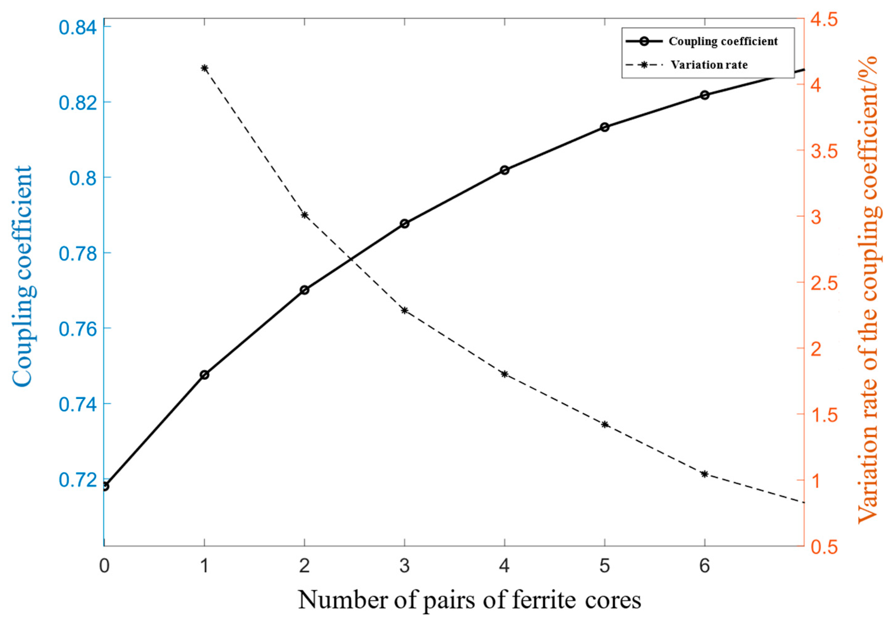
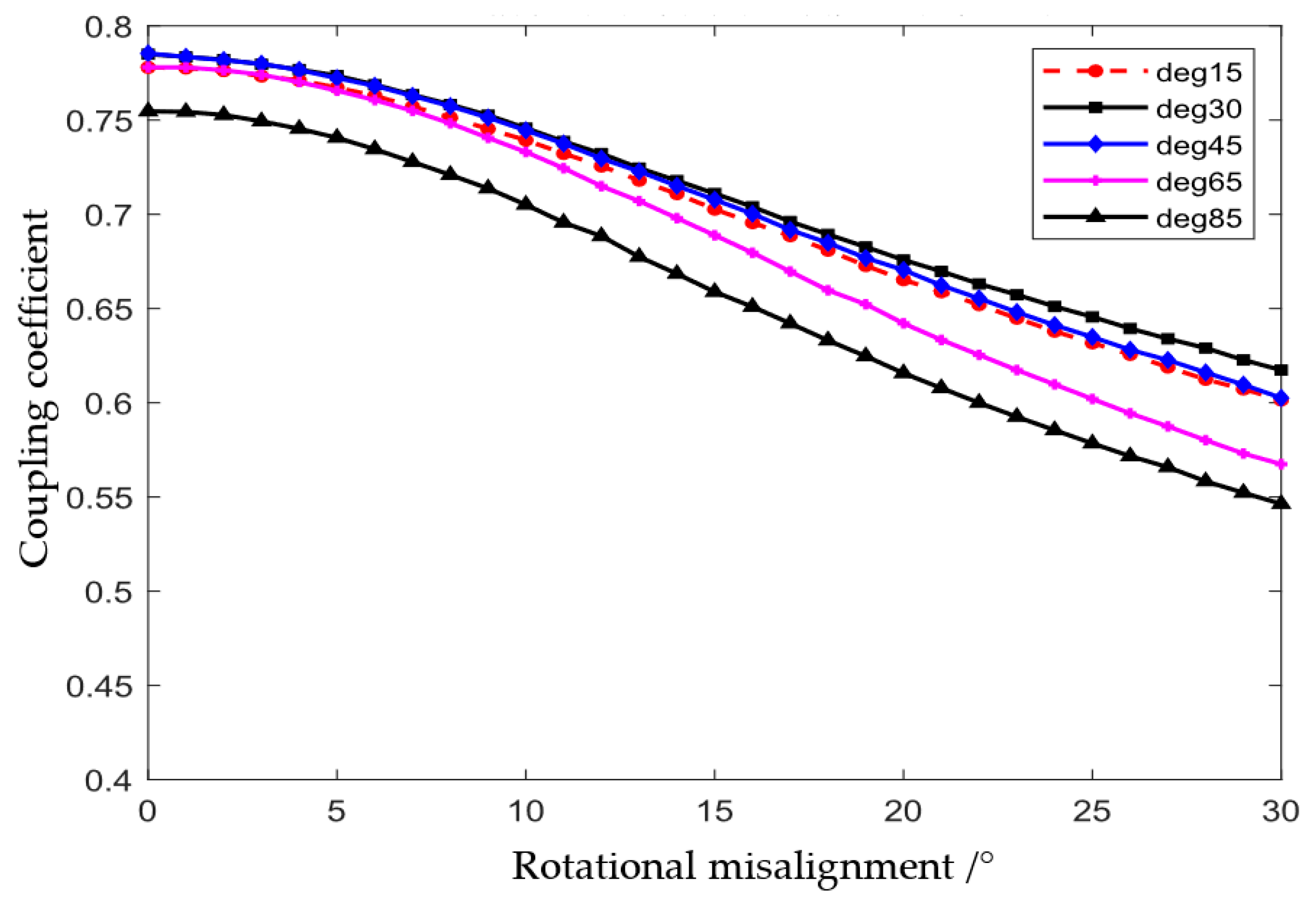
2.3. Optimization of the Coupler

In general, a large mutual inductance of the wireless charging system corresponds to a larger power-transmission capability. However, the weight of coils will increase as the mutual inductance becomes larger. This will increase the system cost and the difficulties in buoyancy balance of AUV. Thus, this paper used the NSGA-II algorithm embedded in the optimization toolbox in MATLAB to optimize the turns and width of the coupler. Two objective functions f 1 and f 2 are defined as:
max f 1 ( N 1 , N 2 , D 1 , D 2 ) = M ,   max f 2 ( N 1 , N 2 , D 1 , D 2 ) = m
where m denotes the total weight of the coils. According to the adjustable buoyancy of AUV and the requirement of transferred power, the constrain conditions are given as:
s . t . 0.2 m 0.8 M 110 u H N 1 , N 2 [ 1 , 2 , 3 , ]
Figure 3 illustrates the solution set (Pareto optimal front) of the coils, with the red circle indicating the selected solution that has the smallest winding mass when the mutual inductance satisfies the condition (10). The corresponding turns of the transmitting and receiving coils are 21 and 20, respectively, and the width of the coils is 210 mm and 200 mm. It is important to note that the optimization process aimed to obtain a lighter weight of coils at an expected transferred power and design a possible coil geometry, rather than determine the specific parameters of self-inductance and mutual inductance of the coils.
As AUVs usually experience roll angles after docking operations, the coupler of the wireless charging system should be able to maintain a stable mutual inductance under possible rotational misalignments. To achieve this, this paper deployed ferrite cores for the coils to improve the coupling coefficient, as well as the rotation adaptivity. Additionally, the use of ferrite cores can constrain the magnetic field around the AUV shell, reducing potential electromagnetic interference. Considering the low temperature of seawater, the system used Mn-Zn based ferrite cores (PC95) to design the coupler.
To investigate the impact of ferrite cores on the coupler, the coils without ferrite cores and with three pairs of ferrite cores were simulated in ANSYS Maxwell. The coupler, excited by a 35 kHz–10 A sinusoidal wave, was analyzed in a seawater environment. It can be observed in Figure 4 that the magnetic flux is almost evenly distributed between the two coils without ferrite cores, while the addition of ferrite cores in Figure 5 significantly changes the distribution of the magnetic flux. This is because the magnetic flux prefers the transmission route with lower magnetic resistance. The permeability of ferrite cores is much greater than that of seawater and air inside the AUV.
Figure 6 illustrates the coupling coefficient of the coils and its rate of variation under different pairs of ferrite cores. The number of core pairs varied from 0 to 7 in the simulation. It is observed that as the number of ferrite cores increases, the coupling coefficient also increases. While a larger mutual inductance corresponds to better power-transmission performance, the mass of ferrite cores would also become larger, increasing the burden of buoyancy regulation on the AUV. By observing the variation rate of the coupling coefficient, it is found that when the number of pairs of ferrite cores is greater than three, the growth rate of the coupling coefficient becomes relatively small (less than 2%). This means that the cost to increase the mutual inductance of the coupler becomes larger. Therefore, the WPT system used three pairs of ferrite cores to improve its performance.
Besides the number of ferrite cores, the distribution central angle is also a critical parameter for the coupler. Figure 7 demonstrates the coupling coefficient of the coils at distribution angles of 15, 30, 45, 65 and 85 degrees, respectively. When the rotational misalignment varies, the ferrite cores distributed with a 30-degree central angle outperform in the coupling coefficient. Therefore, the coupler of the WPT system used three pairs of ferrite cores with a 30-degree distribution angle.
A time-varying electromagnetic field can induce eddy-current power loss in conductive media. Seawater is exactly the kind of conductor which increases the extra power loss of the AUV WPT system. Therefore, it was necessary to investigate the potential effect of eddy-current loss on efficiency. The objective of this paper was to develop a 2 kW prototype WPT system. The corresponding simulation result of eddy-current loss around the coils was computed and is shown in Figure 8. It can be seen that the power loss mainly occurs around the ferrite cores. This result agrees with the distribution of the magnetic flux generated by the coils. The total power loss in seawater is about 2% of the transferred power. If a lower power loss is required, the distance between the two coils should be reduced, which may increase the difficulty of docking operations.

3. AUV WPT System

3.1. WPT Circuit

The composition of the AUV wireless charging system is presented in Figure 9. The inverter is powered by a DC source and generates high-frequency alternating-current (AC) power to the primary coil after tuning by the compensation network. Then, a same-frequency voltage is induced on the secondary coil and is rectified after tuning by the compensation network. Finally, the rectifier provides a DC voltage to the charger and transfers the energy to the AUV battery packs. The LCC-S ( L f C 1 C 2 C S ) compensation network was utilized in the system because of its stable transmission performance [18,19]. The key step in designing the circuit was to construct independent controllers at each side to prevent utilizing the signal feedback from the other side; as a consequence, the system can operate robustly in the presence of a signal delay and even interruptions.
In the rest of this paper, the charger and battery are regarded as an equivalent load R o in the analysis. The symbol M denotes the mutual inductance of coupled coils, C o u t denotes the filtering capacitor of the rectifier, and L 1 , L 2 denote the inductance of the primary and secondary coils, respectively. R 1 , R 2 denote the AC resistance of L 1 , L 2 , respectively.

3.2. Topology Design
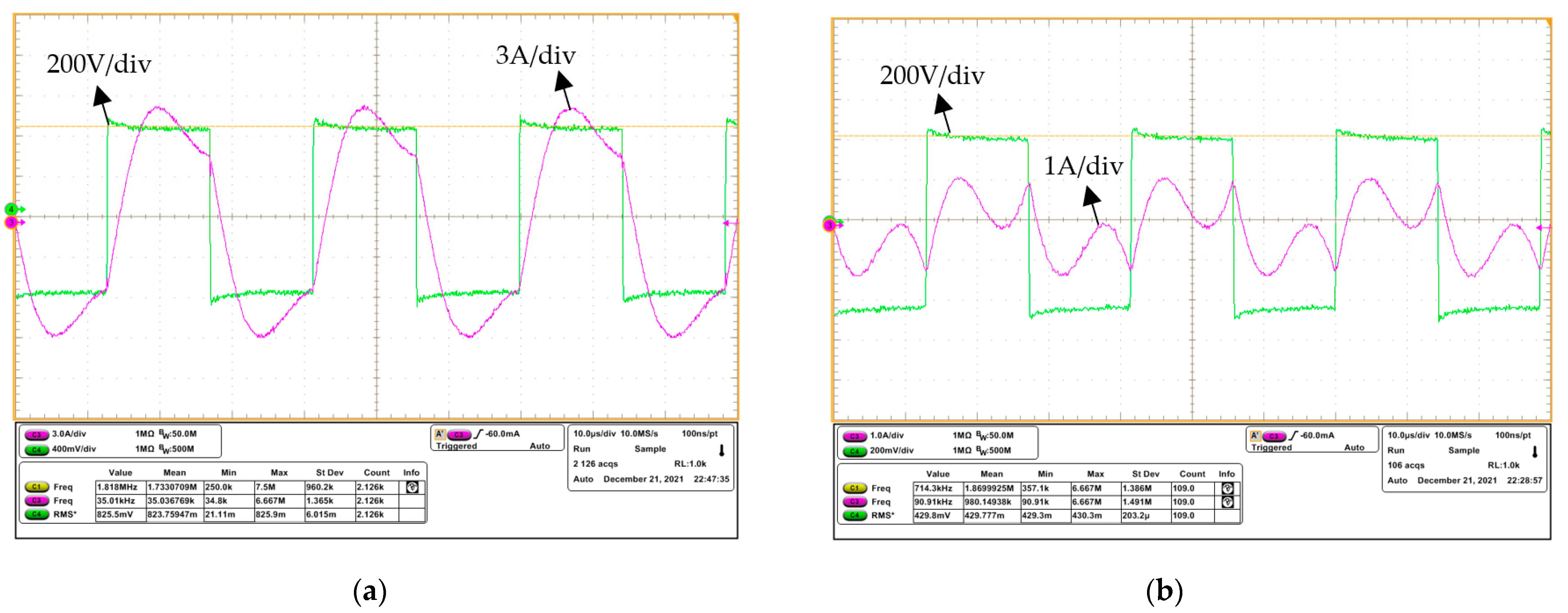
Figure 10 demonstrates the equivalent circuit of the AUV WPT system. The equivalent DC source and load are calculated by:
R e q = 8 π 2 R o
U S = 2 2 U d c π
LCC–S topology is widely used in the WPT community. Here, the parameter-calculation process of the topology is briefly introduced [12]. To achieve a resonant state of the double-sided circuits, three capacitances should satisfy:
C 1 = 1 ω 2 L f , C 2 = 1 ω 2 ( L 1 L f ) , C s = 1 ω 2 L 2
where ω denotes the angular frequency of the system. The reflected impedance to the primary side Z r and the total input impedance Z i n can be written as:
Z r = ω M 2 R e q + R 2
Z i n = j ω L f + 1 j ω C 1 + 1 j ω L 1 + R 1 + Z r + 1 / j ω C 2
Based on the Kirchhoff law, each branch current can be calculated as
I i n = U S Z i n ,
I p = U S I i n L f j ω L 1 + R 1 + Z r + 1 j ω C 2 ,
and
I s = j ω M I p / ( R e q + R 2 ) .
The input power P i n , output power P o u t , output voltage V o u t and the efficiency η of the system can thus be computed as:
P i n = I i n 2 Re ( Z i n ) , P o u t = I s 2 R e q
V o u t = I s R e q ,   η = P o u t / P i n × 100 % .
Figure 11a shows the simulation results of the LCC-S topology-based WPT system. The input voltage of the WPT system is 400 VDC, the operating frequency is 35 kHz, and the AC resistance of both the transmitting and receiving coils is 0.2 Ω in the simulation. It is observed that as the load resistance becomes larger, the load power gradually decreases. However, the voltage ratio of the output voltage to the input voltage remains relatively stable at 0.78. This result proves the robustness of the LCC–S topology in case of load change, making it suitable for most commercial DC–DC chargers that operate under a narrow input range. Figure 11b demonstrates the system efficiency under different mutual inductance of the coupler. It is observed that as the mutual inductance increases, the system efficiency also increases. When the mutual inductance is larger than 110 μH, the variation of the system efficiency is not obvious, and the efficiency stays close to 97%. It should be noted that an appropriate mutual inductance of the coils can not only reduce the weight of the coupler but also provide a high system efficiency.

4. Experiment

Figure 12 demonstrates the experimental platform of the WPT circuit for the AUV docking system. To verify the system performance in sea water environment, we deploy the coils in a saltwater tank with the mass fraction of 2.38% [11]. The equipment and elements used in the experiment are listed in Table 1. The dead time of the inverter is 300 ns to prevent short circuiting of the bridge leg of the inverter. The measured or calculated parameters of the circuit are given in Table 2. It is noted that the charger and battery were substituted by an equivalent load in this research.
Figure 13a demonstrates the coupler performance of the AUV WPT system under different rotational misalignments. It is observed that as the AUV roll angle (rotational misalignment) becomes larger, the coupling coefficient becomes smaller. The coupler with ferrite cores has higher mutual inductance than that without ferrite cores. It is noted that the coupler with ferrite cores has a smaller decline rate compared to that without cores. This result indicates that the ferrite cores can help improve the rotation adaptivity of the AUV wireless charging system.
Figure 13b shows the load power and output voltage of the system under different rotational misalignments. It can be seen that the calculated results are similar to the measured results. The major difference of two curves is possibly caused by the sinusoidal excitation assumption, in which the rectifier with a large filtering capacitance can be regarded as a pure resistor. However, this assumption is only accurate enough under double-sided complete resonance of the compensation network. It is observed that when the roll angle of AUV is 30 degrees, the variation of the output voltage is reduced by about 35 V. This variation is inherently caused by the variation of self-inductance and mutual inductance of coils. If the rectifier is connected to a charger, the charger should be able to adapt to a 35 V voltage variation. Note that although rotational misalignment is possibly inevitable, the efficiency of the developed system maintains relatively stable.
Figure 14 demonstrates the measured waveforms of the inverter at load powers of 2 kW and 200 W, respectively. The voltage probe is isolated and the voltage waveforms at two states are 500× and 1000× attenuated, respectively. It is observed that when the load power is 2 kW, the measured current waveform is very close to a sinusoidal wave, indicating that the system operates in a resonant state. When the transferred power decreases to 200 W, the current waveform becomes distorted. The pure resistor equivalence of the rectifier at this stage is not accurate enough, causing the resonance deviation of the system.
Since the battery charging process is load-changing, the load power and efficiency of the AUV WPT system under different load conditions were investigated in the experiment. It is observed in Figure 15 that the calculated results are nearly consistent with the measured results. The deviation becomes larger as the load value increases. This result corresponds to the resonant state of the system, which deviates from the sinusoidal assumption under a light load. When the load power is 2.2 kW, the system efficiency reaches 94% in a saltwater environment. Even when the load changes from 20~800 Ω, the system efficiency stays larger than 80%, verifying the robustness of the system.

5. Conclusions

The use of radially coupled coils is crucial in the development of an AUV wireless charging system. This technology is better able to suppress electromagnetic interference than traditional coaxial coils. With distributed ferrite cores, the LCC–S-topology-based WPT system is able to maintain a stable output even under possible rotational misalignments of the AUV. The system can achieve a maximum efficiency of up to 94% at 2.2 kW output power in simulated seawater environments. Table 3 provides a summary of the characteristics of the latest prototype for the AUV wireless charging system. The number of black stars indicates the degree of performance depth. The proposed system outperforms state-of-the-art AUV wireless charging systems in terms of transferred power, weight, rotation tolerance, and fabrication difficulty.
Future work will focus on integrating the WPT system into an AUV and docking station for sea trials and applications.

Author Contributions

Conceptualization, M.L. and R.L.; methodology, M.L. and R.D.; software, R.D.; validation, M.L., R.D. and R.L.; formal analysis, R.D.; investigation, M.L.; resources, M.L.; data curation, R.D.; writing—original draft preparation, M.L.; writing—review and editing, M.L.; visualization, M.L. and R.L.; supervision, M.L. and R.L.; project administration, D.L.; funding acquisition, M.L. All authors have read and agreed to the published version of the manuscript.

Funding

This research was financially support by the National Natural Science Foundation of China (52101404), Natural Science Foundation of Zhejiang Province (LY23E090002), and Postdoctoral Research Funding of Zhejiang Province (ZJ202202).

Institutional Review Board Statement

Not applicable.

Informed Consent Statement

Not applicable.

Data Availability Statement

Not applicable.

Acknowledgments

Thanks for the financial support by the National Natural Science Foundation of China (52101404), Natural Science Foundation of Zhejiang Province (LY23E090002), and Postdoctoral Research Funding of Zhejiang Province (ZJ202202).

Conflicts of Interest

The authors declare no conflict of interest.

References

  1. Lin, M.; Yang, C. Ocean Observation Technologies: A Review. Chin. J. Mech. Eng. 2020, 33, 32. [Google Scholar] [CrossRef] [Green Version]
  2. Ma, T.; Li, Y.; Wang, R.; Cong, Z.; Gong, Y. AUV robust bathymetric simultaneous localization and mapping. Ocean Eng. 2018, 166, 336–349. [Google Scholar] [CrossRef]
  3. Lin, M.; Lin, R.; Yang, C.; Li, D.; Zhang, Z.; Zhao, Y.; Ding, W. Docking to an underwater suspended charging station: Systematic design and experimental tests. Ocean Eng. 2022, 249, 110766. [Google Scholar] [CrossRef]
  4. Sato, Y.; Maki, T.; Masuda, K.; Matsuda, T.; Sakamaki, T. Autonomous Docking of Hovering Type AUV to Seafloor Charging Station Based on Acoustic and Visual Sensing; IEEE Underwater Technology: Busan, Republic of Korea, 2017; pp. 1–6. [Google Scholar]
  5. Song, W.; Cui, W. An Overview of Underwater Connectors. J. Mar. Sci. Eng. 2021, 9, 813. [Google Scholar] [CrossRef]
  6. Granger, R.P.; Baer, C.; Gabriel, N.; Labosky, J.; Galford, T.C. Non-contact wet mateable connectors for power and data transmission. In Proceedings of the 2013 OCEANS-San Diego, San Diego, CA, USA, 23–27 September 2013; IEEE: Piscataway, NJ, USA, 2013; pp. 1–4. [Google Scholar]
  7. Baer, C.M.; Alten, M.; Bixler, G.; Fredette, L. Non-Contact Wet Mateable Connector. In Proceedings of the IEEE-OCEANS 2009, Biloxi, MS, USA, 26–29 October 2009. [Google Scholar]
  8. Kan, T.; Mai, R.; Mercier, P.; Mi, C.C. Design and Analysis of a Three-Phase Wireless Charging System for Lightweight Autonomous Underwater Vehicles. IEEE Trans. Power Electron. 2017, 33, 6622–6632. [Google Scholar] [CrossRef]
  9. Yan, Z.; Song, B.; Zhang, Y.; Zhang, K.; Mao, Z.; Hu, Y. A Rotation-Free Wireless Power Transfer System with Stable Output Power and Efficiency for Autonomous Underwater Vehicles. IEEE Trans. Power Electron. 2019, 34, 4005–4008. [Google Scholar] [CrossRef]
  10. Yang, C.; Lin, M.; Li, D. Improving Steady and Starting Characteristics of Wireless Charging for an AUV Docking System. IEEE J. Ocean. Eng. 2020, 45, 430–441. [Google Scholar] [CrossRef]
  11. Lin, M.; Li, D.; Yang, C. Design of an ICPT system for battery charging applied to underwater docking systems. Ocean Eng. 2017, 145, 373–381. [Google Scholar] [CrossRef]
  12. Cai, C.; Wu, S.; Zhang, Z.; Jiang, L.; Yang, S. Development of a Fit-to-Surface and Lightweight Magnetic Coupler for Autonomous Underwater Vehicle Wireless Charging Systems. IEEE Trans. Power Electron. 2021, 36, 9927–9940. [Google Scholar] [CrossRef]
  13. Wang, T.; Zhao, Q.; Yang, C. Visual navigation and docking for a planar type AUV docking and charging system. Ocean Eng. 2021, 224, 108744. [Google Scholar] [CrossRef]
  14. Yang, C.; Wang, T.; Chen, Y. Design and analysis of an omnidirectional and positioning tolerant AUV charging platform. IET Power Electron. 2019, 12, 2108–2117. [Google Scholar] [CrossRef]
  15. Teeneti, C.R.; Truscott, T.; Beal, D.; Pantic, Z. Review of Wireless Charging Systems for Autonomous Underwater Vehicles. IEEE J. Ocean. Eng. 2021, 46, 68–87. [Google Scholar] [CrossRef]
  16. Yan, Z.; Zhao, C.; Hu, Q.; Wu, M.; Qiao, L.; Zhang, K.; Hu, Y. An Underwater Inductive Power Transfer System with a Compact Receiver and Reduced Eddy Current Loss. J. Mar. Sci. Eng. 2022, 10, 1900. [Google Scholar] [CrossRef]
  17. Sallan, J.; Villa, J.; Llombart, A.; Sanz, J.F. Optimal Design of ICPT Systems Applied to Electric Vehicle Battery Charge. IEEE Trans. Ind. Electron. 2009, 56, 2140–2149. [Google Scholar] [CrossRef]
  18. Lee, S.B.; Jang, I.G. Layout Optimization of the Receiver Coils for Multitransmitter Wireless Power Transfer Systems. IEEE J. Emerg. Sel. Top. Power Electron. 2017, 5, 1311–1321. [Google Scholar] [CrossRef]
  19. Yan, Z.; Zhang, Y.; Zhang, K.; Song, B.; Mi, C. Underwater wireless power transfer system with a curly coil structure for AUVs. IET Power Electron. 2019, 12, 2559–2565. [Google Scholar] [CrossRef] [Green Version]
Figure 1. Coil installation in the AUV.
Jmse 11 01180 g001
Figure 2. Geometry of the single-turn winding: (a) oblique view; (b) front view; and (c) side view.
Jmse 11 01180 g002
Figure 3. Solution set of the coil optimization.
Jmse 11 01180 g003
Figure 4. Simulation of the coupler without ferrite cores: (a) the coil model; (b) the front view; and (c) the side view.
Jmse 11 01180 g004
Figure 5. Simulation of the coupler with 3 pairs of ferrite cores: (a) the coil model; (b) the front view; and (c) the side view.
Jmse 11 01180 g005
Figure 6. Coupling coefficient under different pairs of ferrite cores.
Jmse 11 01180 g006
Figure 7. Coupling coefficient under different pairs of ferrite cores.
Jmse 11 01180 g007
Figure 8. Eddy-current loss in sea water.
Jmse 11 01180 g008
Figure 9. AUV wireless charging circuit.
Jmse 11 01180 g009
Figure 10. Equivalent circuit of the AUV WPT system.
Jmse 11 01180 g010
Figure 11. Simulation of the WPT system: (a) the load power and voltage gain under different loads; and (b) system efficiency under different mutual inductance.
Jmse 11 01180 g011
Figure 12. Experimental platform of the WPT system: (a) WPT system; and (b) coupler.
Jmse 11 01180 g012
Figure 13. System performance under different rotational misalignment: (a) coupling coefficient vs. rotational misalignment; and (b) load power and output voltage vs. rotational misalignment.
Jmse 11 01180 g013
Figure 14. Waveforms of the inverter (the green waveforms indicate the inverter voltage, and the waveforms in magenta indicate the inverter current): (a) load power at 2 kW; and (b) load power at 200 W.
Jmse 11 01180 g014
Figure 15. Output power and efficiency under different loads.
Jmse 11 01180 g015
Table 1. Equipment and elements used in the experiment.
EquipmentBrand (Parameters)
Power sourceKeysight N8762 (600 V/8.5 A)
ControllerDSP-TMS320F28335
MOSFET QP1~QP4G1M080120B
Diode D1~D4MUR30120PT-BP
Table 2. Measured or calculated parameters in experiment.
ParameterValue
Coil inductance L 1 and its AC resistance R 1 183.13 μH, 0.17 Ω
Coil inductance L 2 and its AC resistance R 2 180.02 μH, 0.17 Ω
Compensation capacitance C 1 117.8 nF
Compensation capacitance C 2 121.4 nF
Compensation inductance L f 175.5 μH
Compensation capacitance C s 114.2 nF
Operating frequency f35 kHz
Table 3. Comparison of existing AUV wireless charging systems (five solid stars indicate full marks).
Coupler TypeCoaxial Spiral Coils [10]Fit-to-Surface
Coils [12]
Three-Phase
Coils [8]
Curly Coils [19]This Paper
Maximum efficiency (DC-DC)90.0%
(in seawater)
95.1%
(in air)
92.4%
(in air)
95.0%
(in air)
94%
(in salt water)
Power680 W1 kW1 kW1 kW2.2 kW
Weight of coupler★★★★☆★★★★☆★★★☆☆★★☆☆☆★★★☆☆
Electromagnetic interference★★★★★★★☆☆☆★★★☆☆★★★★☆★★☆☆☆
Rotation Tolerance★★★★★★★★☆☆★★★★☆★★☆☆☆★★★★☆
Easy to fabricate★★★☆☆★★★★☆★★★☆☆★★★★★★★★★☆
Disclaimer/Publisher’s Note: The statements, opinions and data contained in all publications are solely those of the individual author(s) and contributor(s) and not of MDPI and/or the editor(s). MDPI and/or the editor(s) disclaim responsibility for any injury to people or property resulting from any ideas, methods, instructions or products referred to in the content.

