Article

Experimental Study on the Effect of the Blade Tip Distance on the Power and the Wake Recovery with Small Multi-Rotor Wind Turbines

1
College of Electrical, Energy and Power Engineering, Yangzhou University, Yangzhou 225127, China
2
Guangling College, Yangzhou University, Yangzhou 225000, China
*
Authors to whom correspondence should be addressed.
These authors contributed equally to this work.
J. Mar. Sci. Eng. 2023, 11(5), 891; https://doi.org/10.3390/jmse11050891
Submission received: 12 February 2023 / Revised: 7 April 2023 / Accepted: 20 April 2023 / Published: 22 April 2023
(This article belongs to the Special Issue Advances in Offshore Wind)

Abstract

:
In order to investigate the output power and wake velocity of small multi-rotor wind turbines compared to single-rotor wind turbines, which operate in the same swept area at various blade tip distances, this paper used the wind tunnel test method to examine single-rotor wind turbines with diameter D of 0.4 m and 0.34 m corresponding to the triple-rotor wind turbines and double-rotor wind turbines with a single rotor diameter D of 0.24 m, respectively. The experimental results indicated that, without rotation speed control, the triple-rotor wind turbine produced more power than the single-rotor wind turbine with an equivalent swept area and that the output power tended to rise initially and then fall as the distance between each rotor increased. Moreover, the power increase reached a maximum of 8.4% at the 0.4D blade tip distance. In terms of wake measurement, triple-rotor wind turbines had smaller wake losses and faster recovery rates than single-rotor wind turbines. The smaller the blade tip distance, the earlier the wake merged and fused and the faster the recovery rate. In designing small multi-rotor wind turbines, the above discussion can serve as a guide.

1. Introduction

Wind energy, a sustainable energy source, has unmatched advantages over traditional energy sources. Even compared with other renewable energy sources, wind energy is recognized as the most commercially viable energy source in the world, and its development prospects are immeasurable. Renewable energy sources contribute significantly to meeting global energy demands and protecting the environment. The development of renewable energy sources has been rapid globally, and wind energy is among the most challenging [1]. Due to the continuous efforts of scholars around the world, small- and medium-size wind turbines with lower power are more mature than large-size wind turbines. Wind turbines of small sizes have several advantages over large-size turbines, including smaller dimensions, less weight, longer lifespan, and easier installation [2]. However, small-size wind turbines also have disadvantages, such as covering more areas per unit of power and the wind energy utilization factor being lower compared to that of large-size wind turbines. Consequently, addressing the shortcomings of small- and medium-size wind turbines is a significant area of future wind energy research.
Combining the current problems of large and small wind turbines, many scholars have focused on multi-rotor wind turbines. There has been increasing competition between multi-rotor wind turbines and large-scale wind turbines. The multi-rotor wind turbine was created to address various drawbacks of large wind turbines, such as transportation challenges, installation challenges, and maintenance challenges [3]. In addition, multi-rotor wind turbines can solve the problem of low power generation and large space requirements of small-size wind turbines. Yoshida et al. [4] conducted numerical simulations of 14 MW multi-rotor wind turbines consisting of seven wind turbines with a capacity of 2 MW, which included three different wind models with decay constants of 6, 12, and 24. The results showed that the large aerodynamic disturbances between the wind rotors increased wind turbine output power as well as the total load but reduced the load caused by the torque at the bottom of the tower and the top of the tower. Two types of wind turbines were compared in terms of power characteristics by Sandhu et al. [5]. Multi-rotor wind turbines produce more electricity and are less expensive to install than single-rotor wind turbines. The aerodynamics of two and three DAWTs (diffuser-augmented wind turbines), which were placed close together in the same plane normal to a uniform flow, were examined by Goltenbott et al. [6]. As compared to a single-rotor turbine, power increased by up to 9% and 5% in each of the triple-rotor and double-rotor configurations. According to McTavish et al. [7], it was possible to improve wind farm performance by limiting turbine lateral separations. According to study findings, triple-rotor wind turbines had an efficiency increase of over 10% above single-rotor wind turbines at a blade tip distance of 0.5D. For wind turbines with additional pressure diffusers, Goltenbott et al. [8] demonstrated that aerodynamic interactions between rotors help to increase the output power of multi-rotor wind turbines by up to 9% in comparison to a single-rotor wind turbine swept to the same extent. Huang et al. [9] compared the production of wind–solar hybrid power using single-rotor and multi-rotor wind turbines. The study showed that multi-rotor wind–solar hybrids performed better at low wind speeds (wind speed less than 7.2 m/s) than single-rotor wind–solar hybrids. DTU (Technical University of Denmark) collaborated with Vestas to build a demonstration of the multi-rotor wind turbine. A 900 KW multi-rotor wind turbine that was formed by four V29–225 KW wind rotors was installed on a 74 m tower at the DTU [10]. The results revealed that at lower wind speeds, the power increased by 2% due to the interaction between wind rotors.
Compared to single-rotor wind turbines, multi-rotor wind turbines have some advantages, not only in terms of power output but also in terms of wake recovery. Hebbar et al. [11] researched multi-rotor wind turbines using an LES (large eddy simulation) with an actuation line model to analyze the effect of incoming shear flow on wake recovery. Multi-rotor wind turbine structures showed earlier wake recovery, less velocity deficit, and better wake uniformity than single-rotor structures. Seven 2 MW multi-rotor wind turbines were analyzed by Chasapogiannis et al. [12] using a wind turbine-based CFD (computational fluid dynamics) model. They observed that the wakes merged into one at approximately twice the wind turbine diameters downstream. Individual multi-rotor wind turbine wake was explored by Bastankhah et al. [13], who discovered that their wake recovery characteristics were identical (blade tip distance is 0.1D). The impact of the number and rotation direction of single-rotor wind turbines on the wake recovery was also investigated, and it showed no effect. Ghaisas et al. [14] studied multi-rotor wind turbines through LES (blade tip distance is 0.05D). Multi-rotor wind turbines recovered from wakes faster and had lower wake turbulence kinetic energy because their perimeter-to-swept area ratio was twice that of single-rotor wind turbines. However, the grids used in these studies were relatively coarse (i.e., a maximum of 40 grid points on the diameter of the wind turbine), which was not enough to accurately analyze the near-wake structure. Ghate et al. [15] studied a multi-rotor wind farm with five units perfectly aligned and arranged in the streamwise direction (blade tip distance is 0.1D, 0.2D, and 0.5D, respectively). The research confirmed that multi-rotor wind farms had low wake loss and turbulence intensity. Zhang et al. [16] studied co-planar multi-rotor wind turbines, which were built to have a larger unit capacity at reduced blade lengths. The interaction impact of the blade tip vortices was discovered using the ALM (augmented Lagrange method)-LES approach, which revealed how multi-rotor wind turbines’ aerodynamic performance and flow field characteristics were regulated. The results showed that the blade tip vortices did not interact much when the blade tip distance was 0.1D. The wake recovery rate of multi-rotor turbines with the same total swept area, power, and thrust was faster than that of single-rotor turbines with the same size and power, according to the study conducted by Vestas in partnership with DTU [10].
Compared to single-rotor wind turbines, multi-rotor wind turbines might have a more complex system configuration. Ismaiel et al. [17] developed an aeroelastic tool to study the dynamic responses of a 2xNREL (National Renewable Energy Laboratory) 5 MW double-rotor wind turbine. The developed tool has been verified by comparing the results of a single-rotor configuration to a FAST analysis for the same simulation conditions. Results of the simulations have shown that the elasticity of the tower should be considered for studying tower dynamic responses. An integrated study on the different concepts of multi-rotor wind turbines was conducted by Givaki et al. [18]. Both AC (alternating current) and DC (direct current) can be used to create the multi-rotor wind turbine’s collection network. Each connection option’s price and dependability were analyzed. With the same number of units and a similar distribution network architecture, the wind power-producing system could be compared to a wind farm. Giger et al. [19] presented a novel wind turbine. Five rotors were stacked in a star pattern in the proposed turbine’s multi-rotor arrangement. Each rotor drive train combined up to 12 generators in a multi-generator concept. Simulations were utilized to show how this idea could be applied and what it could accomplish in practice. A multi-rotor medium-voltage modular wind turbine architecture was suggested by You et al. [20]. Each cell consisted of a turbine rotor, a PMSG (permanent magnet synchronous generator), and a converter. The advantages of this wind turbine structure include greater wind power capture, increased dependability, lower shipping and installation costs, ease of expansion to the higher power, grid voltage ratings, and fault-tolerant operation capabilities. The first study on a high-fidelity linear time-invariant aeroelastic model of multi-rotor wind turbines with three-bladed rotors was given by Filsoof et al. [21]. The outcomes demonstrated that there were no aeroelastic instabilities in the triple-rotor wind turbine. The dynamics of the lower rotors were altered dramatically in terms of natural frequencies and damping ratios when comparing the rotor modes of the single-rotor and triple-rotor wind turbines. This indicated that using a rotor of single-rotor in a multi-rotor design would not be the best option.
The XRC (X-rotor concept) and MRS (multi-rotor system) turbines were mentioned by McMorland et al. [22] as two potential approaches to lower energy costs. Jamieson et al. [23] conducted an extensive study of the large-scale multi-rotor wind turbine concept (blade tip distance is 0.05D). A study of the aerodynamic interference between the wind turbines and the overall unit load was established for a 20 MW multi-rotor system comprising 45 wind turbines with a single output power of 444 kW. Based on similarity scale analysis and predictions, the rotor mass scale and the total mass and dimensions of the primary drive section were determined as 1/ n , where n is the number of rotors in a multi-rotor wind turbine system. This scaling revealed that the aerodynamic bending moment and mass of several important components change in a cubic manner, suggesting that the mass and cost of numerous small wind rotors may be far lower than those of a single rotor with the same rated power. Finally, compared to a 20 MW single-rotor wind turbine, the initial cost would rise to 118%, whereas the cost of electricity generation was expected to fall to 85%. The price of multi-rotor wind turbines has also been predicted by Sandhu et al. [24]. The results of the study showed that megawatt-class multi-rotor wind turbines cost nearly 15% less than single-rotor wind turbines with the same power rating. Generally speaking, the blade cost of multi-rotor wind turbines could decrease, and the tower and other equipment costs will increase. However, multi-rotor wind turbines also have some shortcomings. Ismaiel et al. [17] mentioned that the main challenges of multi-rotor wind turbines are the complexity of the support structure, the yaw system, and the aerodynamic interaction between the rotors close to each other. Secondly, the increase in aerodynamic characteristics may be accompanied by an increase in cost and the influence of tower load.
Moreover, the wind turbine performance would also be affected by turbulence. Chu et al. [25] investigated the effects of ambient turbulence on the wake flows and power production of a horizontal-axis wind turbine. The experimental results revealed that the power production in the grid-generated turbulent flows was slightly higher than that in the uniform flow. Li et al. [26] analyzed the effect of turbulence intensity and wind shear on the power characteristics of a horizontal axis wind turbine (HAWT). When T.I. = 1.4%, 8.0%, and 13.5% at the blade pitch angle of β = 4°, the optimum power coefficients were 0.308, 0.321, and 0.298, respectively. Moreover, the thrust coefficient decreased with the increase in pitch angle. For the optimum pitch angle, the maximum power and thrust coefficients were obtained at as = 0.0558, showing smaller values than the results of wind shear as = 0.1447. These results were important for the development of HAWT suitable for the turbulent environment. In a study from China, Lu et al. [27] used a 2 kW horizontal axis wind turbine as the unit model for a multi-rotor horizontal axis wind power system. Based on the wind accuracy at the cut-in wind speed, a rudder design was done to analyze the impact of wind shear on power generation. The results showed that multi-rotor wind turbines with rudder yaw produced more electricity than single-rotor wind turbines with active yaw. Ten 50 W horizontal axis wind turbines were employed in a multi-rotor wind turbine power-generating system and tested the wind shear coefficient where the wind turbines were located, according to Zhao et al. [28]. The results showed that the larger the radius of the wind turbine, the lower its installation height, and the larger the wind shear coefficient, the greater the variation in load during blade rotation. Wind shear can be successfully minimized by substituting a few small wind turbines for a single large one.
The primary focus of domestic and foreign researchers has been on (1) Whether multi-rotor wind turbines produced more power than single-rotor wind turbines with equal swept areas; and (2) whether multi-rotor wind turbines had larger wake losses and quicker recovery than conventional single-rotor wind turbines. Since the majority of the current research was conducted when blade tip distances were 0.05D, the relationship between output power and wake recovery of multi-rotor wind turbines with varied blade tip distances was not explored. In this paper, we examined the ideal tip distribution distance for multi-rotor wind turbines, as well as the variation law of various features, including 0.1D, 0.4D, and 0.9D blade tip distances. Additionally, previous research on multi-rotor wind turbines focused mostly on the uniform incoming flow, while very little work was done on turbulent incoming flow. The aim of this paper was to examine the features of multi-rotor wind turbines operating in turbulent environments in more detail. In this paper, we refer to the low turbulence conditions as uniform flow cases. Finally, conclusions were given in conjunction with this investigation. It was a guide to the promotion of low-cost open-loop control small wind turbines using these results for simulations and power predictions.

2. Experimental Methodology

In this paper, a low-speed wind tunnel at Yangzhou University was used to conduct all tests. The wind tunnel has two test sections: a low-speed test section and a high-speed test section. The high-speed test section size is 3 m × 1.5 m × 3 m, and the low-speed test section size is 3 m × 3 m × 7 m. For the high-speed test section, the maximum speed is 50 m/s, and for the low-speed section, the maximum speed is 25 m/s. The wind speed is regulated by a variable frequency motor. In the experiment, the inflow velocity is 10 m/s, the rotation speed can approach 2000 RPM, and the chord length near the tip is about 1 cm. Therefore, the Reynolds number is about 1.84 × 10⁴ to 2.93 × 10⁴ with chord length as the characteristic length. A reduction in Reynolds number leads to a reduction in the aerodynamic efficiency of small wind turbines, as is found in similar wind tunnel tests in [29,30]. A draft design for the multi-rotor wind turbine was created in the first step. Figure 1 shows multi-rotor wind turbine models of the horizontal and triangular arrangements that were designed.
The diameter of the single-rotor wind turbine is D. In the multi-rotor wind turbine, the diameter of each small rotor is d, and the distance between each rotor is s. Line 1 represents the hub of the triple-rotor wind turbine’s upper rotor, whereas line 2 represents the hub of the lower rotor. The wind turbines all used the DTU-LN221 airfoil, which was part of the DTU-LN2 family of low-noise airfoils with 21% relative thickness. DTU designed and developed this family of airfoils. The design method of our blade is referred to in [31].
Figure 2 shows a correlation between blade chord length and twist angle. The single-rotor diameter of multi-rotor wind turbines did not vary in the follow-up study to compare the relationship between the number of rotors and wake recovery. An investigation was conducted on the relationship between the wake recovery of the double-rotor wind turbine and the triple-rotor wind turbine. The diameter of the single rotor of double-rotor and multi-rotor wind turbines is 0.24 m, and the corresponding equivalent swept area of the single-rotor wind turbine is about 0.34 m and 0.4 m, respectively.
Normally, the volume of dynamic torque sensors conforming to the range is too large and difficult to connect directly between a wind turbine and its motor for wind turbines with a diameter of D = 0.4 m, so improvements must be made to the power measurement method. The shaft power of the wind turbines was obtained via an indirect method in this study. Similar to the method described in [32], the specific method involved the use of two sets of selected motor models, one of which was connected to a DC power source to provide stable power mimicking the wind turbine’s rotation. The other motor produced voltage and current by acting as a generator. Generator output current, torque, and rotation speed were measured at different loads with multiple sets of power. Fitting and interpolating the measured data to obtain the curvilinear relationship of output current, torque, and rotation speed. In actual wind tunnel measurements, the wind rotor is directly connected to the generator, so the wind rotor’s torque equals the torque of the motor. The power acquisition method used in this paper comes from [33]. The wind rotor was connected to the DC motor by coupling in the actual measurement. A sampling resistor with a resistance of 0.05 Ω and a potentiometer with adjustable resistance (0–100 Ω) was inserted in series with the motor output circuit. In this paper, two types of motors were used to measure wind turbine output. The single-rotor wind turbine with large output power used the WS-31ZYT57-R motor, and the multi-rotor wind turbine used the FF-180SH motor. Although different motors were used, their different efficiencies had little effect on the experiment. This is due to the fact that we measure the current and voltage for speed fitting in our experiments, and then we convert them to shaft power, so the issue of efficiency can be ignored. However, different from Huang et al. [33], the larger wind speed in this study led to the difficulty of rotation speed control. The turbine could not adjust the rotation speed in a wide range of 10 m/s. Therefore, this influence of the rotation speed was not considered. Due to high costs, complex control systems, and other reasons, most small wind turbines on the market also do not operate under the optimal tip speed ratio. Based on the above background, we have not considered the impact of rotational speed in the aerodynamic research of multi-rotor wind turbines. Therefore, the experimental conclusions are only aimed at small wind turbines without rotational speed control and have specific practical value for wind–solar complementary lighting systems and household small wind turbines. For various conditions in this paper, the wind turbine rotates with the free stream in an open-loop control manner. This similar test setup was also found in [29,34].
In the wind tunnel test depicted in Figure 3, DANTEC, Denmark, supplied a multi-channel thermostatic hot-wire anemometer with an accuracy of 0.001 V and a relative error of less than 0.1% to measure velocity and turbulence. High precision and high sensitivity are two features of the hot-wire anemometer. In this paper, the hot-wire anemometer used a two-dimensional probe. It went through a two-point calibrator for wind speed calibration, where the probe also needed to go through an angular calibration to improve accuracy. At the same time, the temperature sensor (model 90P10) was placed in the wind tunnel for real-time temperature correction to achieve the maximum accuracy of the measurement value. The uncertainty could be divided into systematic uncertainty and random uncertainty. Because this experiment used precision instruments, the systematic uncertainty error had no significant impact and could be easily overcome by a large number of samples [35]. Additionally, according to the relevant reference [36], the random uncertainty could be averaged through repeated measurements to ensure the accuracy of the data.
In the wake measurement scheme, the measuring points were set up horizontally. The wake measurement position is shown in the figure at the hub height. Two groups of wakes were measured for the triple-rotor wind turbine, line 1 and line 2. The wake axial position measurement method is shown in Figure 4. The wake monitoring locations were placed at axial distances of 1D, 2D, 3D, 5D, and 8D. The X direction is designated as parallel to the wind rotor plane and the tower, whereas the Y direction is perpendicular to the wind rotor plane. During the test, turbulence grilles were placed at the entrance of the wind tunnel to create turbulent inflow so as to determine how to affect the multi-rotor wake characteristics. Turbulence intensity (T.I.) is defined as the variance of fluctuating velocity divided by local average velocity, as follows:
I u = σ u U ¯ I v = σ v U ¯
In this equation, σ u and σ v , respectively, represents the standard deviation of the fluctuating component of the fluctuating wind velocity in the streamwise direction and the lateral wind direction, and U ¯ represents the average wind speed at the measuring point. The grid turbulence generator that was used in this paper was constructed by an aluminum alloy grid bar and bolt. The width and thickness of the grid were both 3 cm, between the top of the grid shelf and the wind tunnel wall, rubber pads were put in place, and several anchor bolts were put in place at the base.
For flow field measurements, the sample time was 20 s, and the sampling frequency was 5 kHz. A single measurement point yielded a total of 100,000 data points. Before flow field data could be gathered, pitot tubes were utilized to measure the average wind speed at the wind rotor portion and stabilize it around the test wind speed of 10 m/s. References [37,38] contained a description of the detailed design. After the flow field measurement was completed, the T.I. of each measuring point was calculated by the formula. The base T.I. of the free wind tunnel was 0.2%. The grid adopted in this paper corresponds to scheme I (the width and thickness of the aluminum alloy grid both were 3 cm). The turbulence intensity measured was 1.6 m behind the grid, and the average T.I. and integral scale streamwise were 10.5% and 0.0648 m, respectively.

3. Results and Discussion

3.1. Power Characteristics of Multi-Rotor Wind Turbines

Figure 5 shows the relationship between the output power and blade tip distance of the single-rotor wind turbine and the multi-rotor wind turbine with an equal swept area when the wind speed is 10 m/s. In order to be more in line with the actual situation, single-rotor and multi-rotor wind turbines in this figure were all measured by the wind tunnel tests, not by multiplying the ratio relation of sweep area. At a blade tip distance s/d of around 0.2, we could see that the power generated by multi-rotor wind turbines differs slightly from that generated by single-rotor wind turbines with the same swept area. Multi-rotor wind turbine output power gradually grew and surpassed that of single-rotor wind turbines as the blade tip distance increased. At a blade tip distance of 0.4D, the output power of the multi-rotor wind turbine reached its maximum. The output of the triple-rotor wind turbine was 8.4% higher than the single-rotor wind turbine of equal swept area, and the output of the double-rotor wind turbine was 7.3% higher than that of the single-rotor wind turbine. As blade tip distance continued to increase, multi-rotor wind turbines continued to produce more energy than single-rotor wind turbines of the equal swept area, with an increase in output of 2.7% for double-rotor wind turbines and 2.3% for triple-rotor wind turbines when it reached 0.9D. The explanation for the increase in total output power of multi-rotor wind turbines might be that the rotors are closer to each other, the interference between the rotors becomes larger, and the interaction of the wake vortex could be enhanced, which leads to a variation of the pressure behind the rotors, thus increasing the flow velocity through the rotor plane. This will be described in detail in the subsequent section on wake analysis.
Compared with the studies of other researchers, whose conclusions were based on very close blade tip distance (generally s/d = 0.05), this study had the maximum power output at a blade tip distance of s/d = 0.4. The explanation for this phenomenon was that the studies of other scholars were based on megawatt-class wind turbines, which rotation speed was low. Meanwhile, this paper was based on a small model, and the rotation speed is very high. The speed difference of almost hundreds of times would change the wind turbine’s interference distance. It is important to note that the results in this experiment are collected from a small wind turbine without an accurate speed control device, which is consistent with numerous small wind turbine products on the market. For a single-rotor turbine, only the complete curve of output shaft power and tip speed ratio with a diameter of 24 cm can be obtained by adjusting the load at the current wind speed, as shown in Figure 5c. The turbine could not adjust the rotation speed in a wide range at 10 m/s in 34 and 40 cm diameter conditions; therefore, we chose the maximum value of the single-rotor wind turbine for comparison. It should be noted that if we calculate the equivalent rotor swept area through a single rotor with a diameter of 24 cm, the output power of the corresponding single rotor with a diameter of 34 cm is about 7.678 W. However, due to not operating at the optimal tip speed ratio, the power of the single-rotor case was only 4.93 W in Figure 5a (with a power coefficient of 0.09), and this data is not the optimal power point for the wind turbine. In addition, when the rotor was placed at a relatively close distance, that is when the wind turbine with a diameter of 24 cm was placed on the tower of multiple wind turbines. Due to the interference between the flow of each wind rotor, the speed of each rotating wind rotor is difficult to control. Therefore, we cannot adjust the speed in a wide range of 10 m/s. Meanwhile, it was found that in such a small wind turbine model, it was very difficult to adjust the speed of the three rotors to ensure the same speed. The maximum rotation speed of the multi-rotor wind turbine was about 1400–1500 r/min. The possible reason for this is the complex interference between the rotating planes. Therefore, it is difficult to consider the effect of rotation speed, similar to the actual small wind turbine products. For a large number of small wind turbines on the market, due to the cost, complex control system, and other reasons, they also do not operate in the optimal tip speed ratio. We acknowledge that in an ideal situation, it is necessary to draw a curve of each rotor output power of the multi-rotor turbine varying with the tip speed ratio. Then the total output power of the wind turbine can be obtained. However, it is difficult to achieve this in the test conditions and actual small wind turbines. Therefore, under the existing experimental conditions, these results are based on small wind turbines without rotational speed control, which is meaningful for wind-solar complementary lighting systems and household small wind turbines, but does not apply to large wind turbines. For all wind turbine scales, we cannot say with certainty that the maximum power generation can be obtained at this ratio. We should continue to investigate the influence of Reynolds number and rotation speed in multi-rotor wind turbines.

3.2. Wake Characteristics of Multi-Rotor Wind Turbines

Figure 6, Figure 7 and Figure 8 compared the wake velocity profiles for line 1 and line 2 of the triple-rotor wind turbine and the equivalent swept area of a single-rotor wind turbine for s/d equal to 0.1, 0.4, and 0.9, respectively. The measuring lines 1 and 2 of the triple-rotor wind turbines were at the height of the rotor hub listed above and below, respectively. As shown on the axes in these figures, the X-direction was the horizontal direction of the cross-section, and the measuring position was at the positive center of the hub of the single-rotor wind turbine or at the symmetrical center of the two hubs of the double-rotor wind turbine when X was zero. The flow passing through the rotor, part of the energy used to do work for the wind rotor, makes the fluid speed less than the inflow velocity, thus forming a velocity deficit phenomenon. It was evident from Figure 6, Figure 7 and Figure 8 that the wake velocity deficit value ∆U/U decreased with increasing axial distance, which showed that the wake velocity of the wind turbine had gradually recovered.
As shown in Figure 6, for line 2, two peaks of velocity deficit were observed at axial distances Y of 1D, 2D, and 3D for blade tip distance s/d = 0.1, whereas the peaks were not easily identifiable at Y = 5D and Y = 8D, which indicated that the wake had merged. Meanwhile, there was also a small peak velocity deficit due to the presence of the tower when Y = 1D and X = 0. At X = 0, a reverse peak can be seen between the two rotors of the triple-rotor wind turbine. With increasing axial distance, the peak became progressively smaller and eventually disappeared at Y = 5D. The main reason for this was that with increasing axial distances, each rotor’s wake gradually expanded, creating a wider distribution, and the fluid outside the wake infiltrated continually. Regarding the extreme of the wake velocity deficit, at Y = 1D, single-rotor and triple-rotor wind turbine extremes were similar in size, and the value was nearly up to 80%, indicating that, at this distance, the wind turbine was entirely in the wake interference zone. While triple-rotor wind turbines exhibited smaller wake velocity deficits at Y = 2D and Y = 3D than single-rotor wind turbines. At Y = 5D, the velocity deficit relative difference between the single-rotor wind turbine and triple-rotor wind turbine became smaller, and at Y = 8D, the velocity deficit was almost the same.
A comparison of Figure 6, Figure 7 and Figure 8 shows the change in the relation of the wake when the triple-rotor blade tip distance varied. The most intuitive difference is that as the distance between wind rotors increases, the hub center distance increases and the wake width of a triple-rotor wind turbine significantly widens. When the blade tip distance s/d was 0.1 and 0.4, the effect of the velocity deficit generated by the tower was still apparent at the axial distance Y = 2D. Whereas at s/d = 0.9, it was clearly visible that the velocity deficit caused by the tower still existed, even affecting wake loss at Y = 3D axial distance. Moreover, it was observed that for the triple-rotor cases, the velocity deficits slightly changed as the blade tip distance increased, and the maximum velocity deficits were all less than in the single-rotor cases.
Besides, in the test range, both the upper and lower parts of the triple-rotor wind turbine recovered faster than that of the single-rotor wind turbine. The faster wake recovery ability was a significant advantage of multi-rotor wind turbines compared with single-rotor wind turbines. The faster wake recovery of the multi-rotor wind turbine is mainly due to the entrain of high momentum flow of inflow velocity as the s/d increases and the interaction of the tip vortex of the multi-rotor turbines. The wake peaks of the triple-rotor below nearly merged when the axial distance Y = 5D and the blade tip distance s/d = 0.1. As the blade tip distance increased, these peaks were still visible at the higher blade tip distances of s/d = 0.4 and s/d = 0.9, suggesting that each rotor operated more independently. It should be noted that velocity deficit is just one indicator. We need to focus on the wider area covered by the wake when we design a multi-rotor of a large s/d ratio. In addition, the influences of the Reynolds number and rotation speed variation are also worth studying.
The comparison of the wake velocity deficit between the triple-rotor and the single-rotor wind turbine is shown in Figure 9 for uniform flow case and turbulent intensity of 10.5%, respectively. The wake velocity deficit under the condition of T.I. = 10.5% was smaller than that of uniform inflow, indicating that the wake recovery of wind turbines under turbulent conditions was quicker than that of uniform inflow. Turbulence reflected the intensity of the fluctuating velocity. The greater the T.I., the greater the velocity fluctuation, thus increasing the penetration collision probability and impacting the intensity of the tip vortex, bound vortex, and center vortex generated by air flowing through blades. In this process, the wake was thoroughly merged and fused, and finally, the wind speed recovered rapidly and tended to be uniform, which was also the reason why the wake recovery was quicker in turbulent than in uniform inflow. It also can be seen from the figure that the velocity deficit of the wake of the triple-rotor wind turbine under turbulent conditions is significantly lower than that of the uniform flow. Compared with a single-rotor, the difference between the triple-rotor wind turbines was more obvious, especially at the positions of 2D and 3D. This demonstrated that turbulence had a higher impact on the triple-rotor’s wake recovery rate than it did on the single-rotor wind turbine. Possibly, this behavior could be explained by the fact that the wake vortex collisions of triple-rotor wind turbines were more apparent in turbulent conditions than they were for single-rotor turbines, necessitating a closer analysis of the T.I. in the wake.
Figure 10 and Figure 11 show the turbulence intensity for single-rotor and triple-rotor wind turbines at the 2D and 3D positions, respectively. As shown in the figure, the single-rotor wind turbine had a higher T.I. than the triple-rotor wind turbine in the wake. Compared with the single rotor of the triple-rotor wind turbine, part of the energy flowing through the single-rotor wind turbine of the equal swept area did more work on the rotor than that of the single rotor of the triple-rotor wind turbine, which made the central wake area formed by the single-rotor wind turbine larger and generated more vortices, including tip vortices, bound vortices, and center vortices, and finally made the T.I. greater. Secondly, the figure also shows that the T.I. of the high turbulent condition was lower than 10.5% at the edge position, and the value was smaller in 3D compared to 2D, which was due to the fact that the turbulence intensity decreased with the increase in the axial distance. In addition, the turbulences inside and outside the wake region could exchange momentum.
The comparison of Figure 10 and Figure 11 also shows that at the high turbulent flow condition with the axial distances Y = 2D and Y = 3D, the peak value of the triple-rotor wind turbine had gradually approached the uniform flow case, whereas in the single-rotor wind turbine case, the value was still higher than the uniform flow, so it could be inferred that the wake vortex generated by the triple-rotor wind turbine had been less affected by incoming turbulence compared with the single-rotor wind turbine. It should be noted that two schemes were used to compare the aerodynamic performance of small wind turbines, and the conclusion was only obtained under the current test results without involving parameter optimization. Further investigations about different parameters (e.g., incoming flow, change of working conditions, and different rotation speeds) need to be performed to find its general change rules.

3.3. Lateral Wake Characteristics

Figure 12 shows the lateral wake characteristics for single-rotor and triple-rotor wind turbines. From this figure, we can see that the lateral wake of the single-rotor wind turbine and the multi-rotor wind turbine decreased with increasing axial distance, which has a similar rule to the streamwise velocity. However, the difference was that the streamwise wake gradually returned to the incoming flow speed as the surrounding wind speed replenished. In contrast, the lateral wake speed weakened as the surrounding uniform wind speed was replenished until it tended to zero (uniform incoming lateral velocity was essentially zero). Positive and negative signs represent the direction of the lateral wake. The left represents the negative, whereas the right is positive when facing the incoming flow.
In this figure, it appears that drastic changes occurred at the two opposite ends of the rotors. This was due to the rapid rotation of the rotors generated by tip speed on each side, respectively, in their respective directions. Furthermore, the results showed that the lateral velocity was highest near the central wake area under the influence of the blade roots. This phenomenon might be attributed to the fact that more central vortices were generated behind the hub and blade roots where turbulence was most intense. These vortices generated and superimposed lateral velocity in response to their rotation. Compared with the single-rotor wind turbine, the triple-rotor wind turbine had a slightly greater lateral speed, and the direction changed more frequently. In addition, because it concerns two rotors on line 2, the lateral wind direction could change frequently. The reason for the change in lateral wind speed might be that the smaller rotor wind turbine had a faster rotation speed, which resulted in more vortices and then a higher speed. Figure 13 shows the change of T.I. at different axial distances of lateral wind for single-rotor and triple-rotor. The distribution was not much different from the streamwise direction, and it shows that the single-rotor wind turbine has a greater T.I. than the triple-rotor wind turbine.

3.4. The Influence of Rotor Numbers on Wake Recovery

Figure 14 compares the single-rotor wind turbine with a diameter of 0.34 m and the double-rotor wind turbine with a 0.24 m rotor diameter for the wake loss at the blade tip distance of s/d = 0.4. The axial distances corresponded to 2, 3, 5, and 8D3 of the axial distance of the triple-rotor wind turbines (D3 is the diameter of the single-rotor wind turbine with the equal swept area as that of the triple-rotor wind turbines). In this figure, the wake distribution for the double-rotor wind turbine looked similar to the triple-rotor wind turbine below, following more minor wake losses and faster recovery for multi-rotor wind turbines. The velocity deficit curves were similar at the identical position, as shown in Figure 15. The wake loss was nearly close at the same axial distance as long as the single-rotor wind turbine was divided into triple-rotor or double-rotor wind turbines. The results also indicated that when s/d = 0.4, the triple-rotor above seems to have little influence on the wake distribution of the rotors below. However, for a multi-rotor wind turbine with the same swept area as a single-rotor wind turbine, the rotor diameter becomes smaller, and the wake loss becomes diminutive. However, the smaller the diameter and the greater number of multi-rotor wind turbines, the units’ overall layout and tower structure would be greatly troubled. Furthermore, it was necessary to investigate whether the smaller the rotor diameter of multi-rotor wind turbines, the lower their cost. Therefore, more research is needed to determine the single rotor’s ideal diameter for multi-rotor wind turbines.
Besides, by using XFlow software, we simulated the condition of the wind tunnel test to perform a numerical analysis (see Figure 16). The vortex structures of the single-rotor wind turbine and the triple-rotor wind turbine were analyzed. Comparing single-rotor wind turbines with triple-rotor wind turbines, single-rotor wind turbines have more turns of vortex development at the tip of the blade than triple-rotor wind turbines. This is mainly because the rotation speed of each wind rotor of the triple-rotor wind turbine is faster than that of the single-rotor wind turbine, which makes the tail vortex break up more quickly. The obvious stratification of the wake velocity at the beginning and the irregularity of the wake velocity after a certain axial distance. From the vortex structure of the triple-rotor wind turbine, it can be seen that the vortices of each small wind turbine have overlapping parts, which indicates that the vortices of each wind turbine of the triple-rotor wind turbine interact with each other, so the collapse of the vortex structure occurs faster, which is also an explanation for the faster recovery of the wake velocity of the triple-rotor wind turbine.

4. Conclusions

In this paper, comparative tests and numerical simulations were carried out between single-rotor and multi-rotor small wind turbines to compare the characteristics in terms of power and wake flow at different blade tip distances. The summary is as follows:
(1)
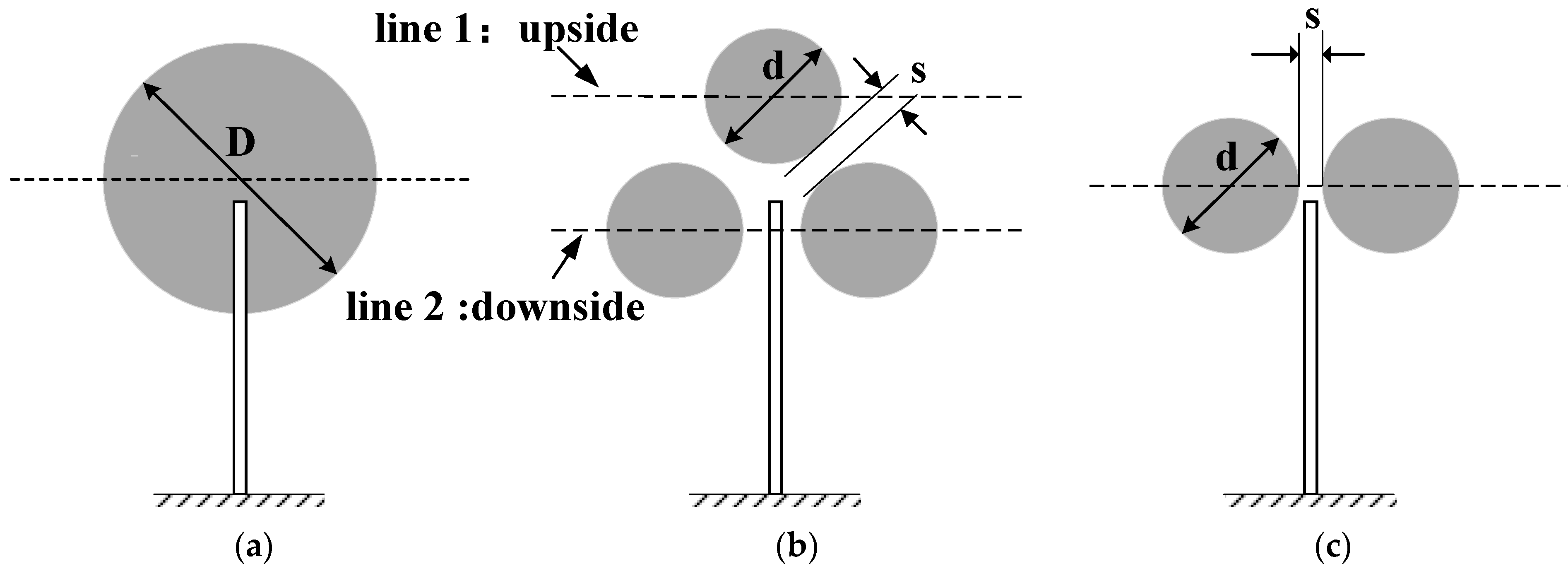
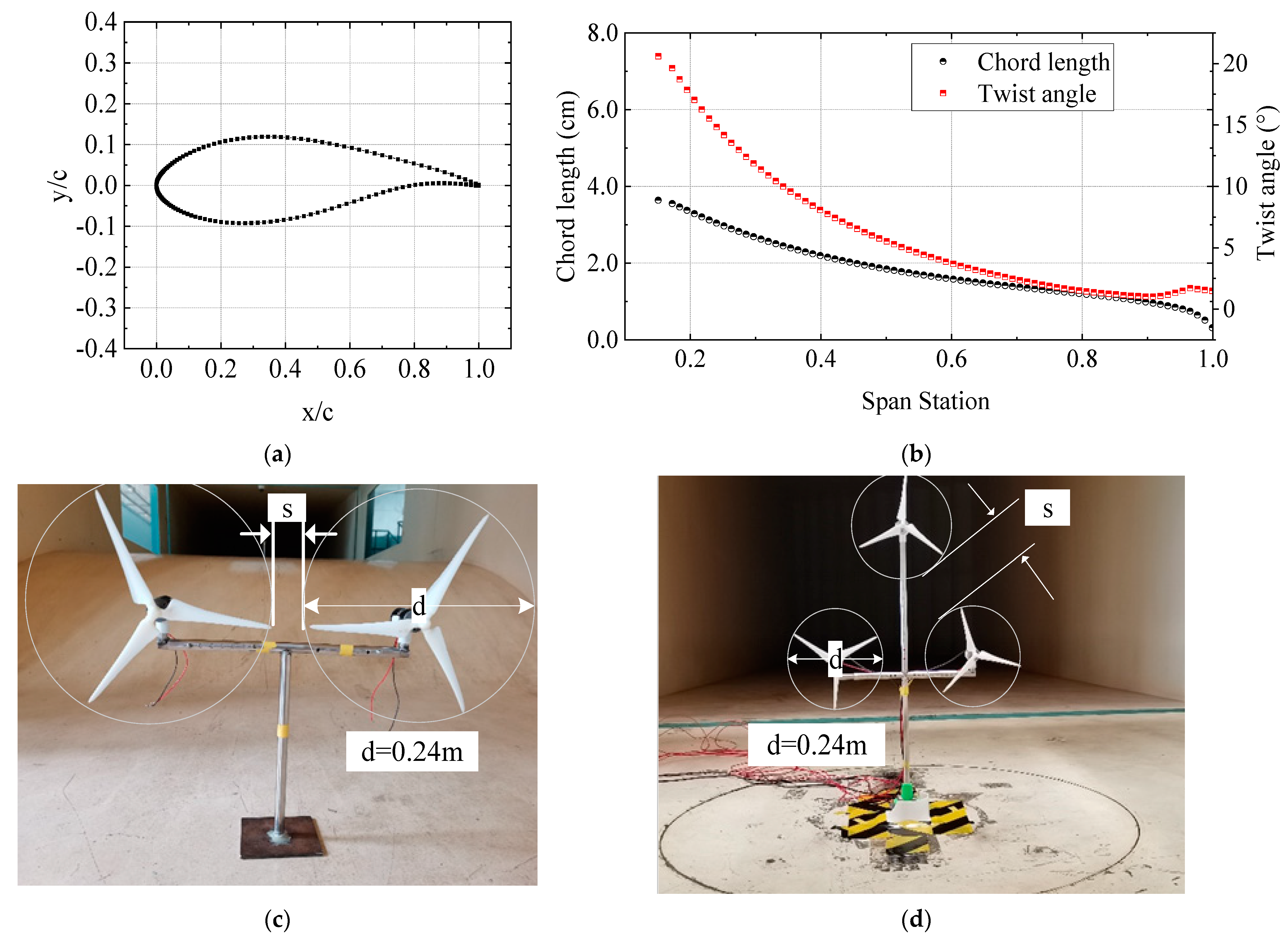
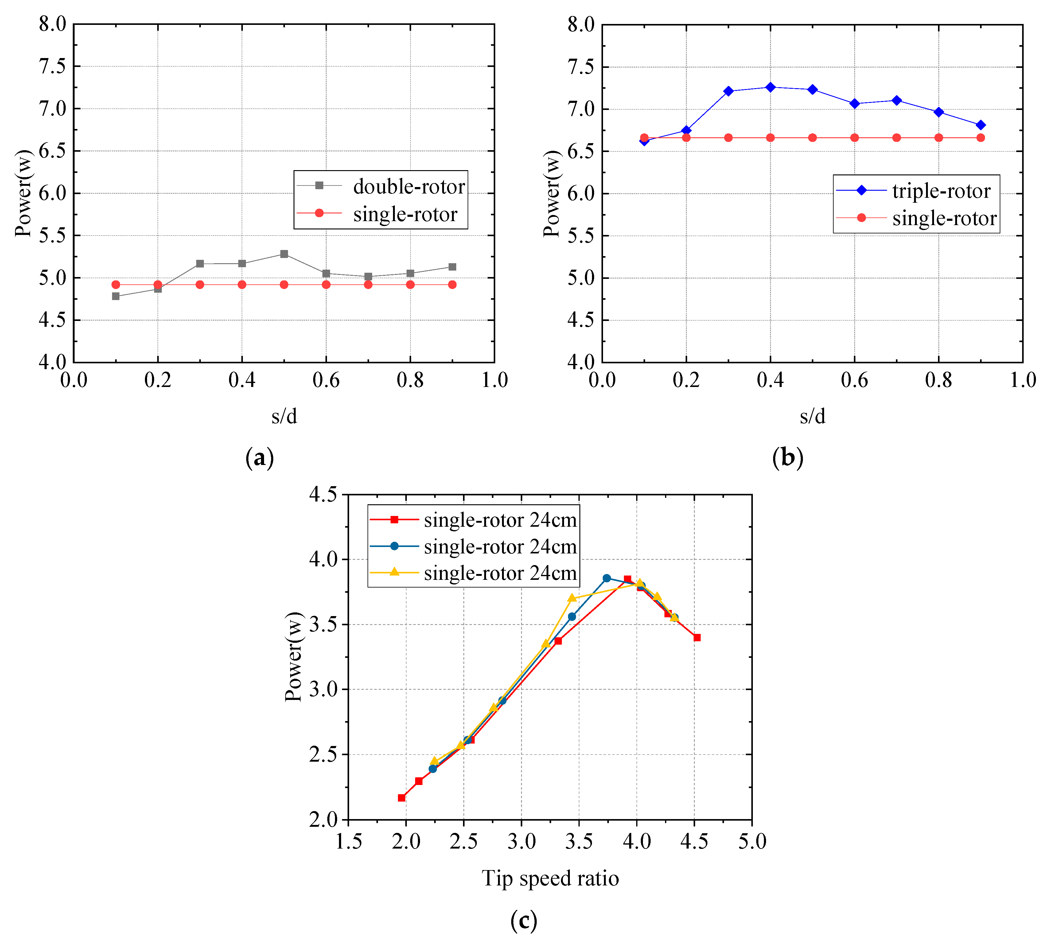
Wind tunnel experiments were conducted to measure the output power of single-rotor and equal-area multi-rotor small wind turbines under the conditions that the rotation speed was not adjusted. These experimental results showed that at s/d = 0.2, the total output power of a multi-rotor wind turbine was close to that of a single-rotor wind turbine with an equal swept area. With the increase in blade tip distance, the output power of multi-rotor wind turbines gradually increased, which was larger than that of the single-rotor wind turbine. At s/d = 0.4, the output power increased the most, by 7.3% and 8.4% for the double-rotor and triple-rotor, respectively. Even at s/d = 0.9, its output power still increased compared with that of the single-rotor wind turbine of the same swept area when the single rotor of the multi-rotor wind turbine operated relatively independently, and the total output power of the double-rotor and triple-rotor wind turbines increased by 2.7% and 2.3%, respectively.
(2)
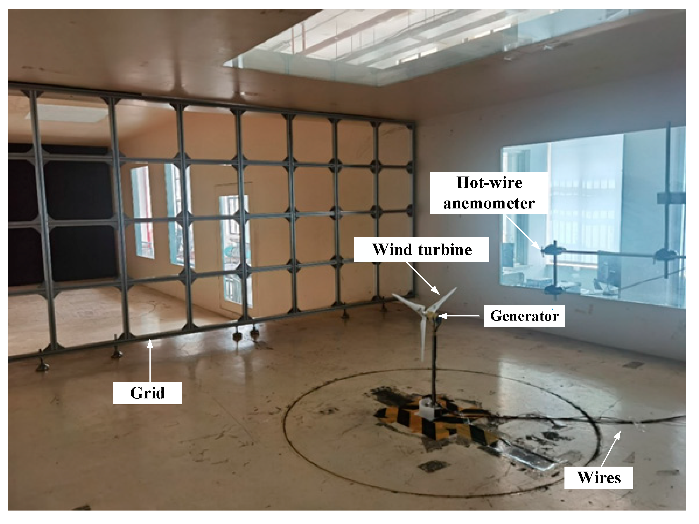
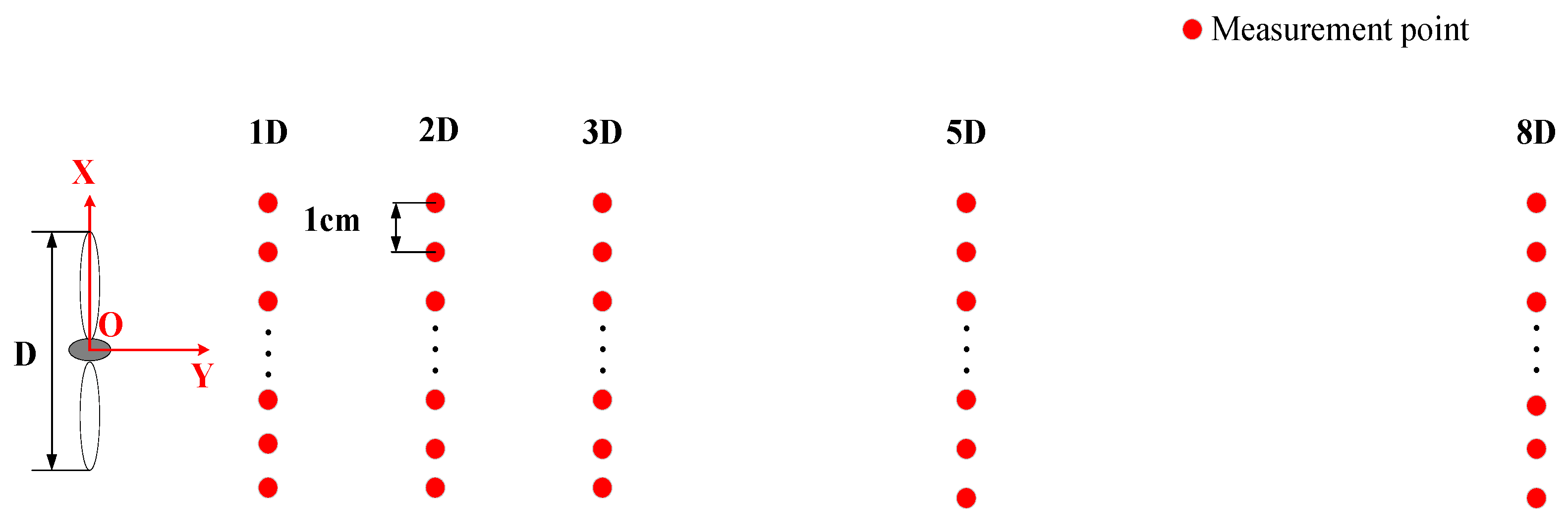
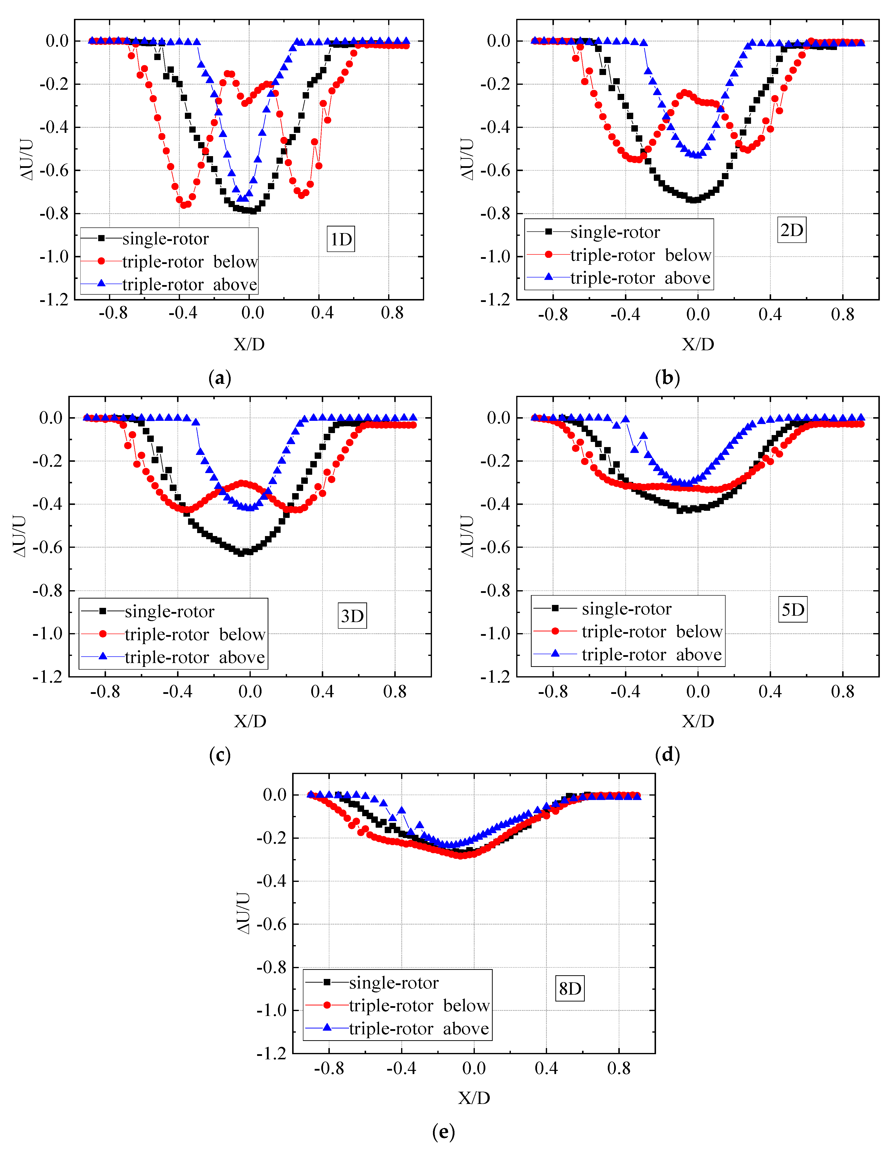
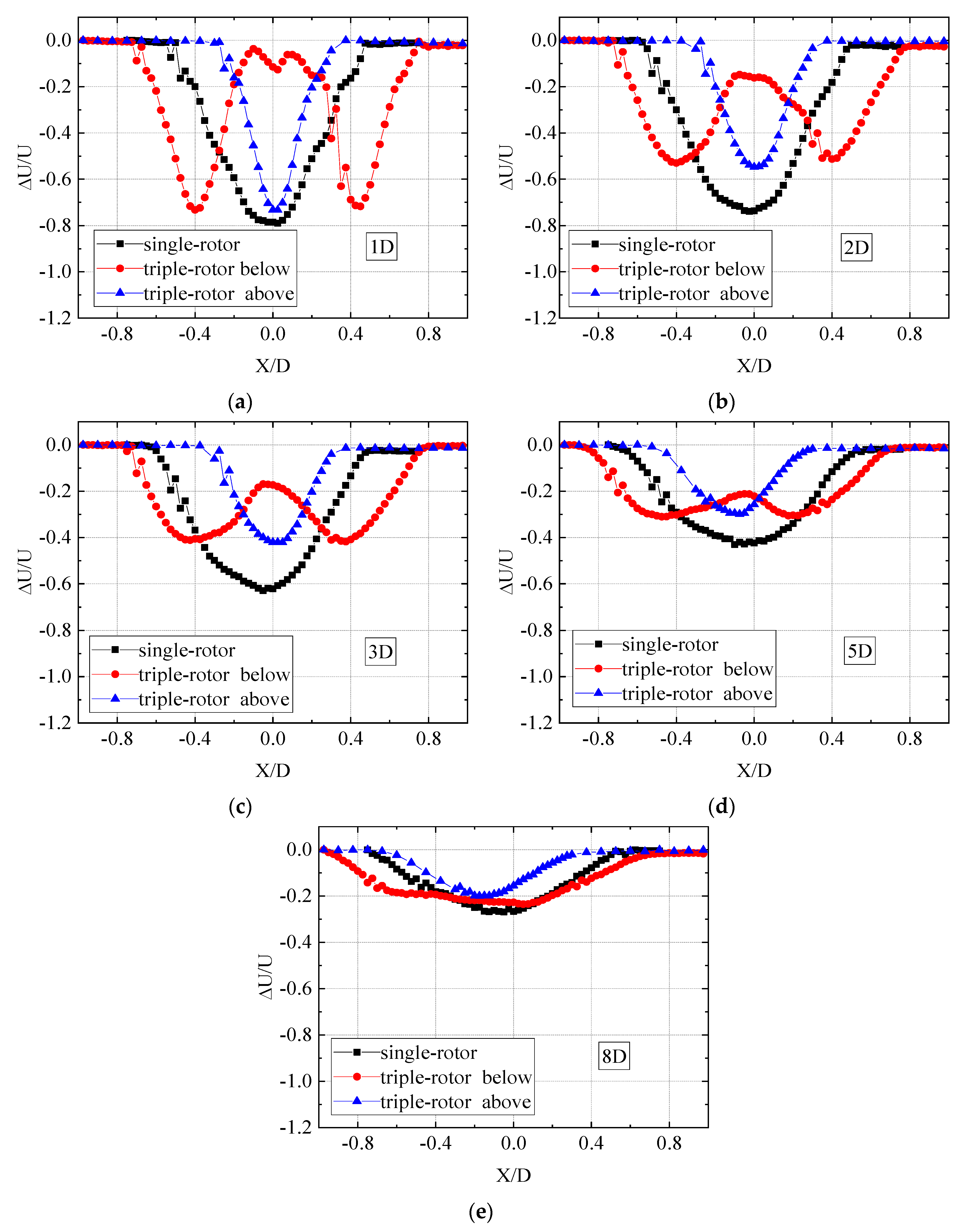
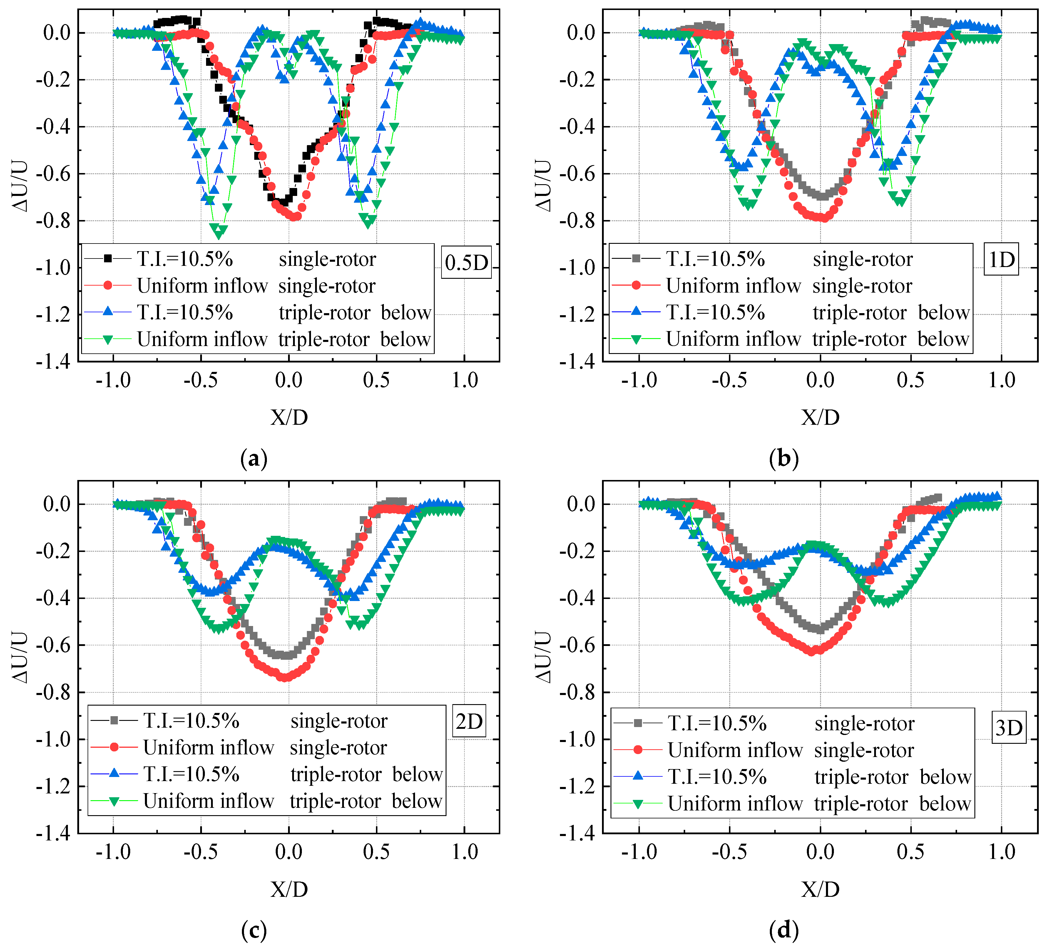
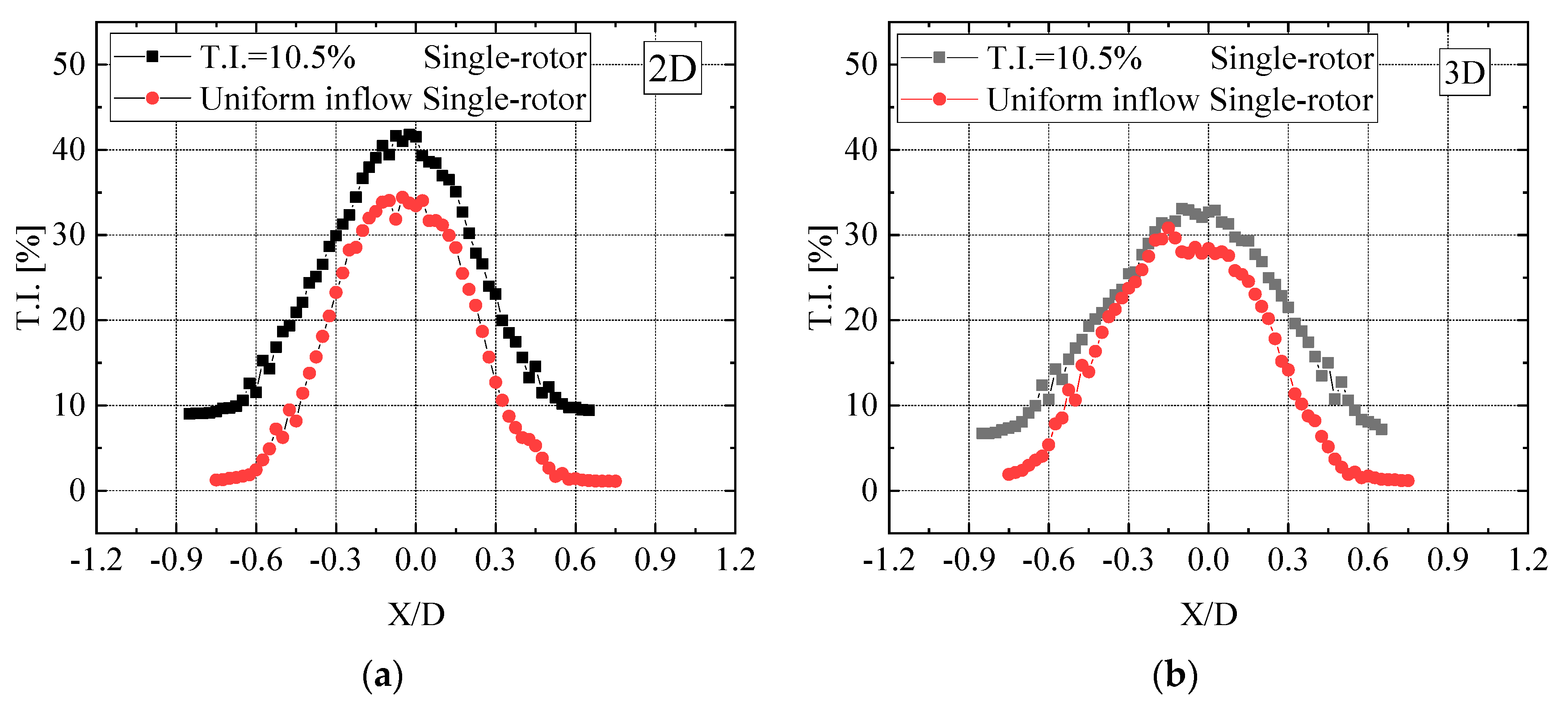
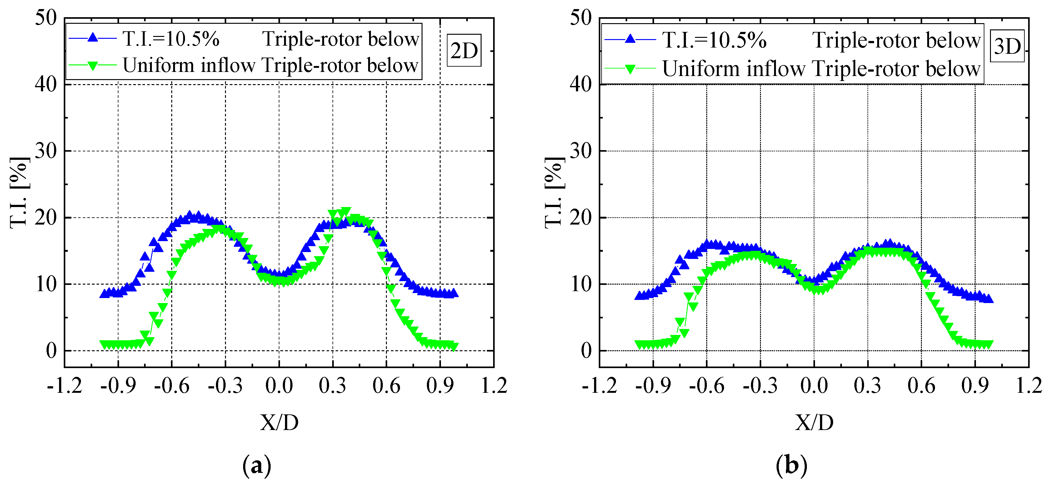
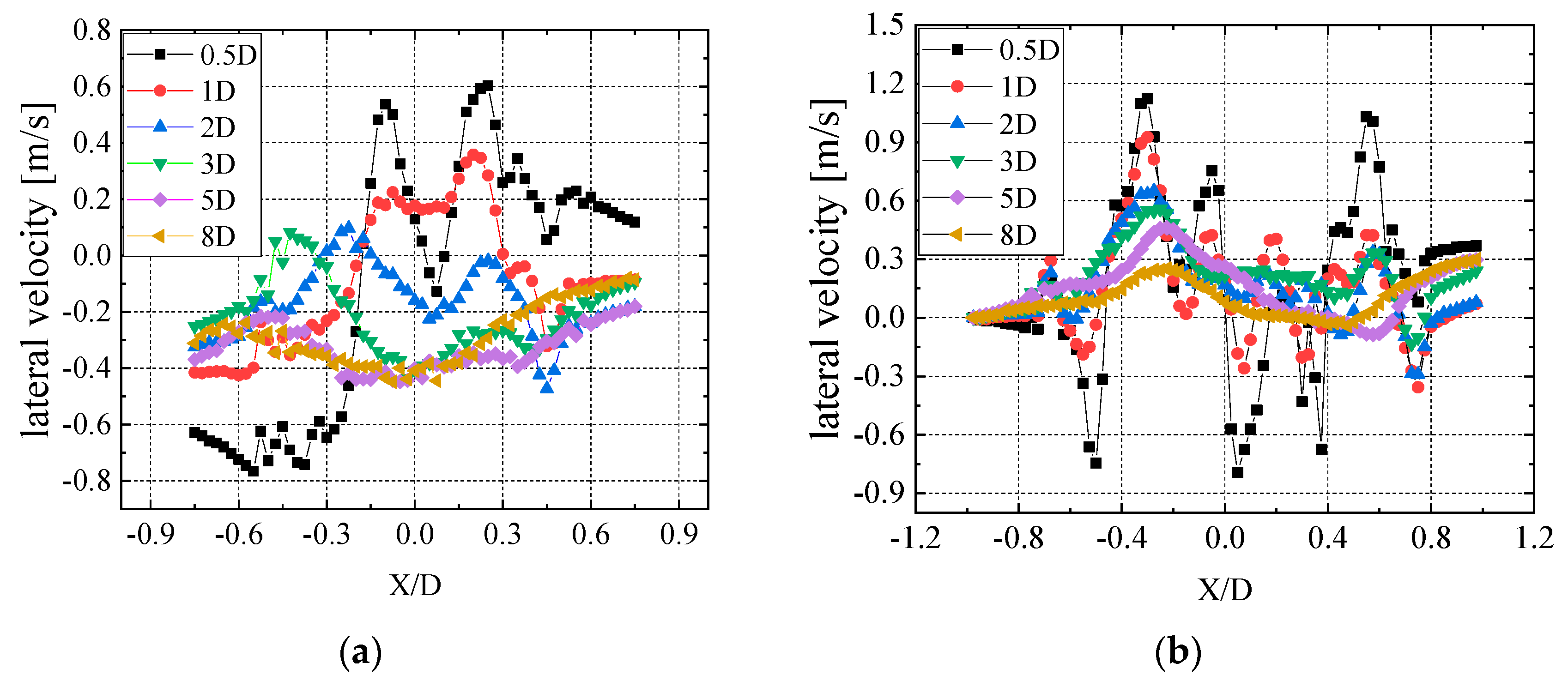
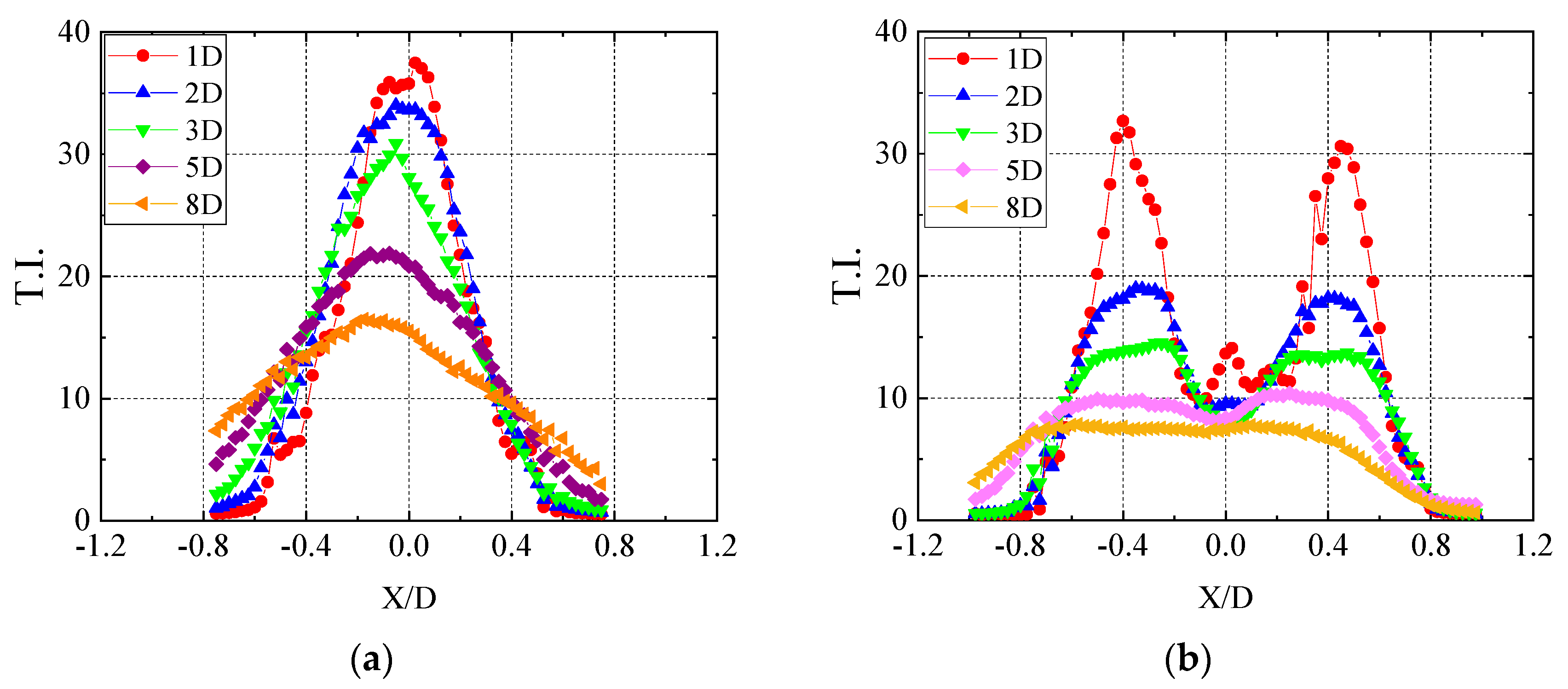
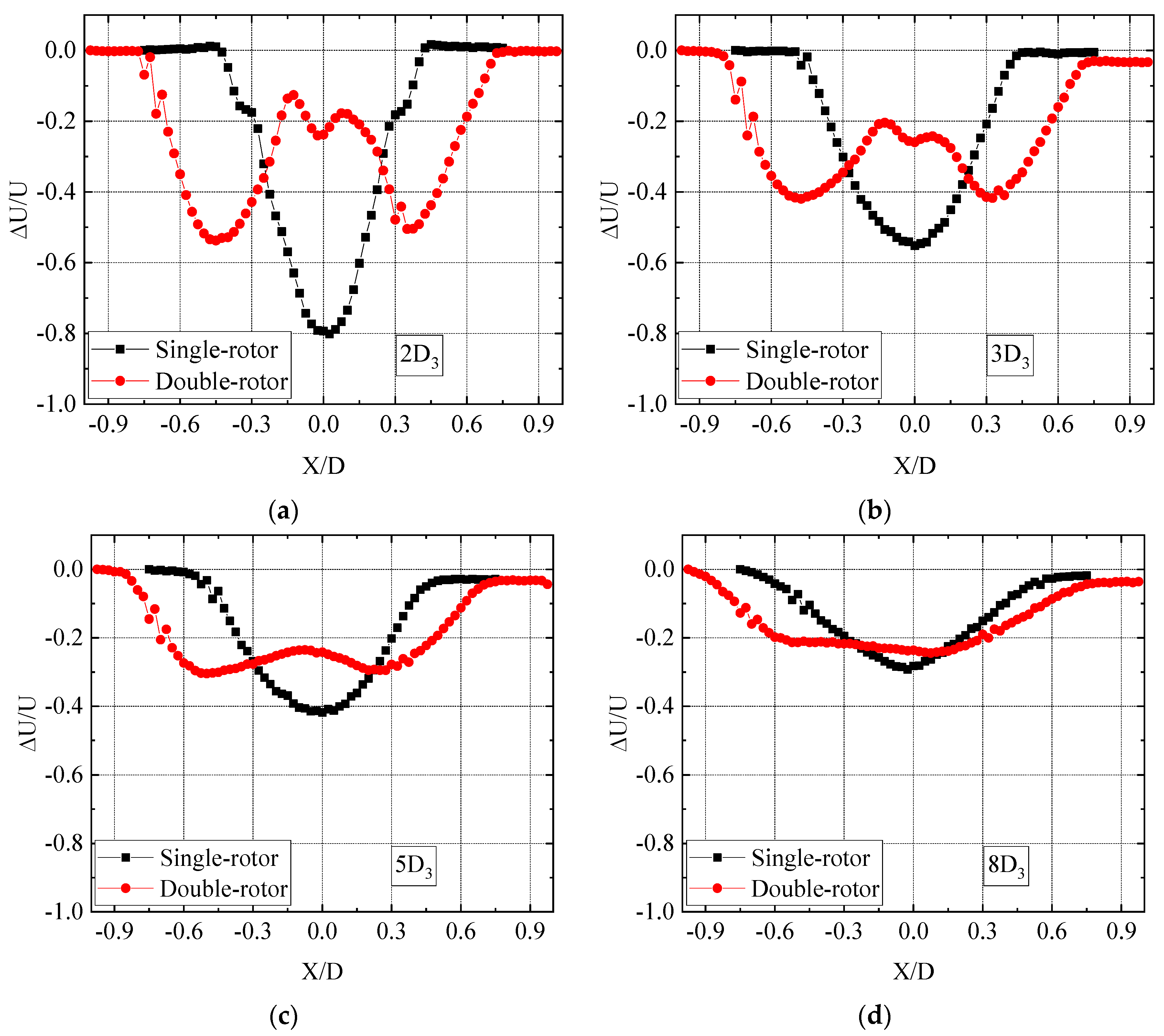
Carried out wake characteristics experiments on three types of wind turbines with equal swept areas: the single-rotor, the triple-rotor, and the double-rotor. The multi-rotor wind turbine had a faster wake recovery ability under uniform inflow than the single-rotor wind turbine of the equal swept area. Whether it was a single or triple-rotor wind turbine, the wake velocity deficit was smaller than that of uniform flow under the condition of T.I. = 10.5%, which also indicated that the wake recovery of the wind turbine was faster than that of uniform flow. The effect of turbulence on the wake velocity recovery of triple-rotor wind turbines was greater than that of single-rotor wind turbines. Under the condition that the incoming flow T.I. was 10.5%, the wake velocity deficit became smaller, and the velocity recovery ability was faster. However, due to the existence of blade tip distance, the wake width of multi-rotor wind turbines was significantly wider than that of single-rotor wind turbines, and the larger the blade tip distance, the wider the wake width. Increasing the blade tip distance did not significantly alter multi-rotor wind turbine wake recovery. Additionally, multi-rotor wind turbines also had a greater lateral velocity than single-rotor wind turbines. The multi-rotor wind turbine’s lateral velocity direction was more complicated, and the change of direction was more frequent. Furthermore, the lateral velocity produced by the multi-rotor wind turbine was higher because each small rotor spun more quickly.
(3)
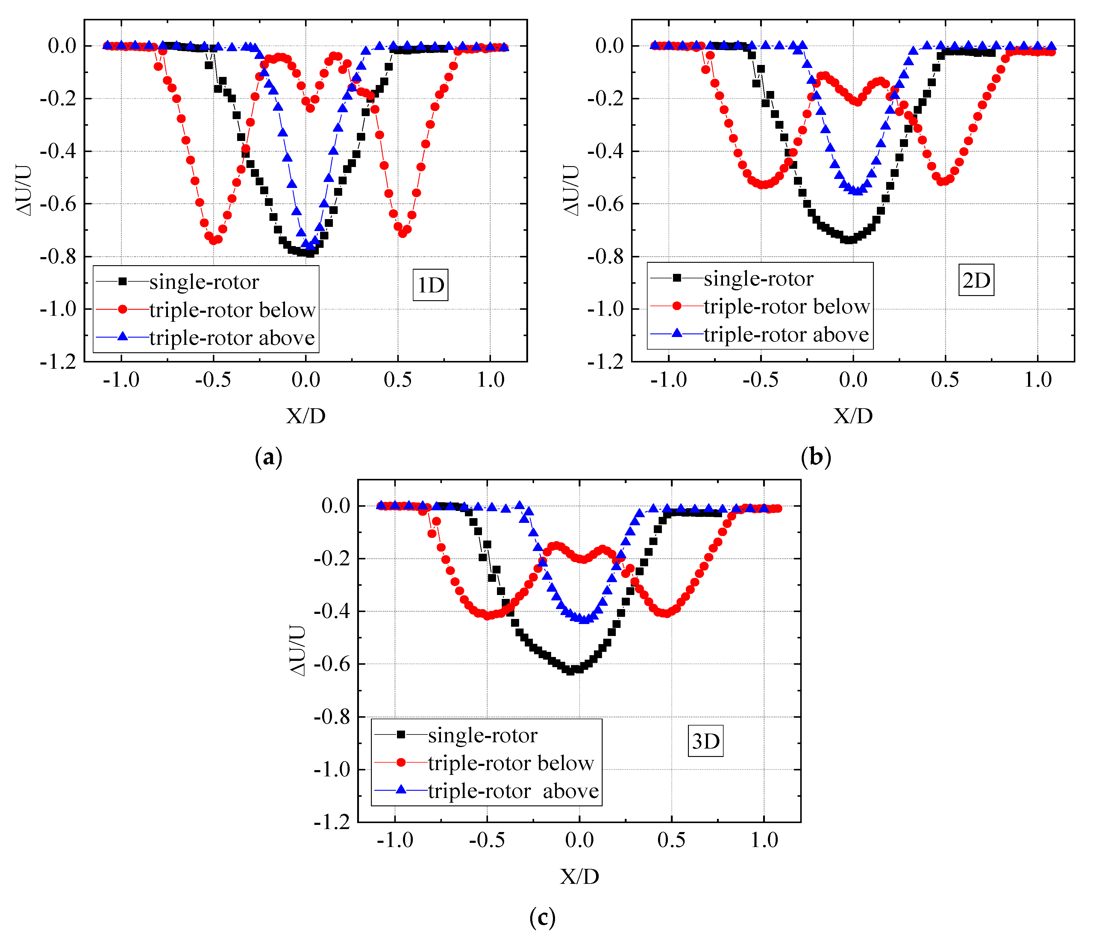
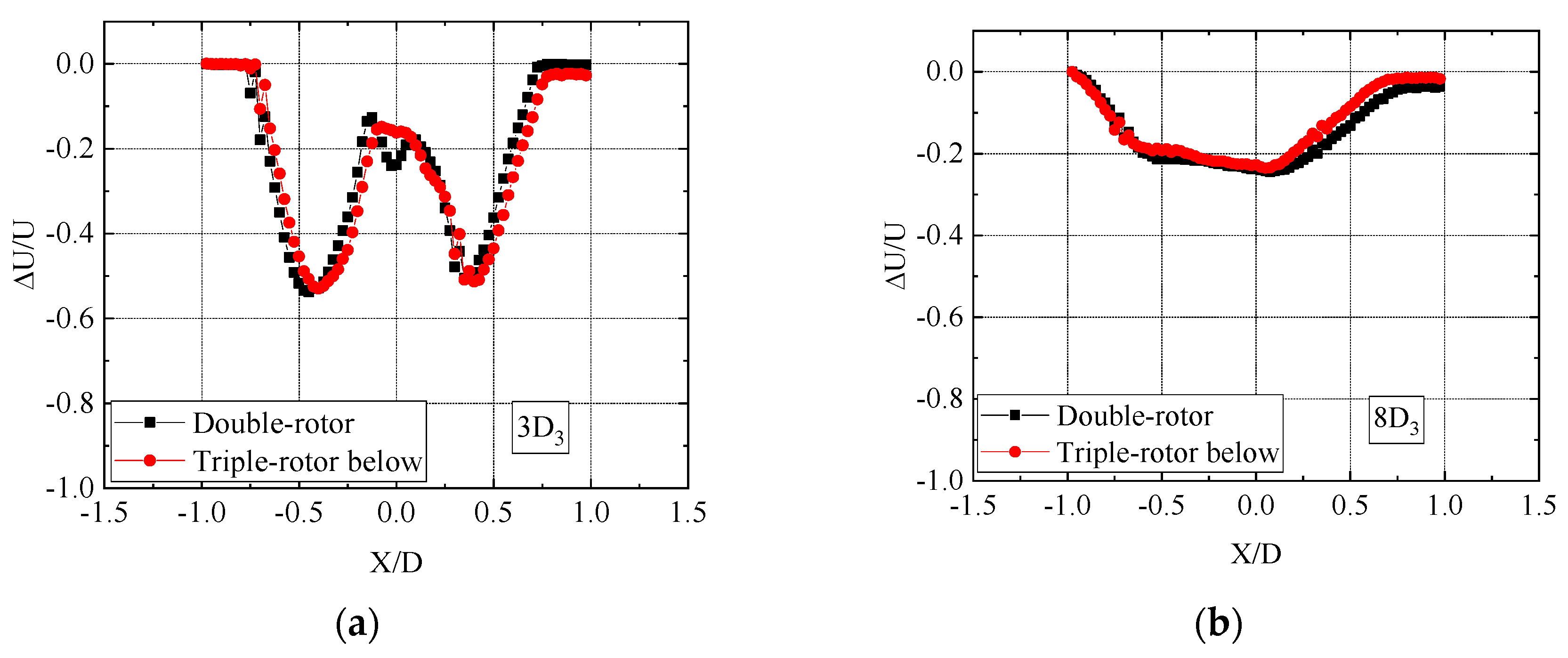
A comparative study of wind turbines with double and triple rotors was conducted. According to the results, the wake loss and recovery capabilities at the same axial distance were similar for multi-rotor wind turbines with equal area splits when the single rotor had the same diameter and was positioned exactly the same way.
The purpose of this paper is to preliminarily verify the influence of different blade tip distances on the power and wake of small wind turbines under conditions without considering the effect of rotation speed changes. The shortcoming of this paper is that due to the presence of blocking ratios and the axial length of the wind tunnel, we are temporarily unable to verify the accuracy of the experiments in a wind tunnel for larger wind turbines with a large s/d ratio. Due to the difficulty of speed adjustment and the fact that it is difficult to adjust the rotation speed between each rotor because of the interference, we did not consider the effect of speed. In view of the speed of large wind turbines being relatively low, the interference between rotors appears to be less significant than that of small wind turbines. So, in the subsequent study, we will use the CFD method for a more accurate study of multi-rotor wind turbines with large s/d rotors.

Author Contributions

Conceptualization, H.Y. and J.Y.; methodology, H.Y. and J.Y.; formal analysis, S.G., K.P. and J.Y.; funding acquisition, J.Y.; writing—original draft preparation, S.G., K.P. and J.Y.; writing—review and editing, J.Y. and H.Y. All authors have read and agreed to the published version of the manuscript.

Funding

This research was funded by the Natural Science Foundation of Jiangsu Higher Education Institutions of China under grant numbers 22KJD480003 and 22KJB510046.

Institutional Review Board Statement

Not applicable.

Informed Consent Statement

Not applicable.

Data Availability Statement

Not applicable.

Conflicts of Interest

The authors declare no conflict of interest.

References

  1. Ilhan, A.; Sahin, B.; Bilgili, M. A review: Diffuser augmented wind turbine technologies. Int. J. Green Energy 2021, 19, 1–27. [Google Scholar] [CrossRef]
  2. Zhang, W.; Deng, Y.C.; Zeng, X.L. Analysis and Evaluation of Small-sized Wind Turbines. Power Syst. Cle. Energy 2012, 28, 82–86. (In Chinese) [Google Scholar]
  3. Elkodama, A.; Ismaiel, A.; Abdellatif, A.; Shaaban, S. Aerodynamic Performance and Structural Design of 5 MW Multi Rotor System (MRS) Wind Turbines. Int. J. Renew. Energy Res. 2022, 12, 1495–1505. [Google Scholar]
  4. Yoshida, S.; Goltenbott, U.; Ohya, Y.; Jamieson, P. Coherence effects on the power and tower loads of a 7 × 2 MW multi-rotor wind turbine system. Energies 2016, 9, 742. [Google Scholar] [CrossRef]
  5. Sandhu, N.S.; Chanana, S. Performance and Economic Analysis of Multi-Rotor Wind Turbine. Int. J. Eng. Technol. 2018, 6, 289–316. [Google Scholar] [CrossRef]
  6. Goltenbott, U.; Ohya, Y.; Yoshida, S.; Jamieson, P. Aerodynamic interaction of diffuser augmented wind turbines in multi-rotor systems. Renew. Energy 2017, 112, 25–34. [Google Scholar] [CrossRef]
  7. McTavish, S.; Rodrigue, S.; Feszty, D.; Nitzsche, F. An investigation of in-field blockage effects in closely spaced lateral wind farm configurations. Wind Energy 2015, 18, 1989–2011. [Google Scholar] [CrossRef]
  8. Goltenbott, U.; Karasudani, T.; Ohya, Y.; Jamieson, P. Aerodynamic analysis of clustered wind lends turbines. In Proceedings of the 8th International Symposium on the East Asian Environment Problems, Fukuoka, Japan, 9–10 December 2014. [Google Scholar]
  9. Huang, Q.; Shi, Y.; Wang, Y.; Lu, L.; Cui, Y. Multi-turbine wind-solar hybrid system. Renew. Energy 2015, 76, 401–407. [Google Scholar] [CrossRef]
  10. Van der Laan, M.P.; Andersen, S.J.; Ramos García, N.; Angelou, N.; Pirrung, G.R.; Ott, S.; Sjöholm, M.; Sørensen, K.H.; Vianna Neto, J.X.; Kelly, M. Power curve and wake analyses of the Vestas multi-rotor demonstrator. Wind Eng. Sci. 2019, 4, 251–271. [Google Scholar] [CrossRef]
  11. Hebbar, U.; Rane, J.D.; Gandhi, F.; Sahni, O. Analysis of interactional aerodynamics in multi-rotor wind turbines using large eddy simulations. In Proceedings of the AIAA Scitech 2020 Forum, Orlando, FL, USA, 6–10 January 2020. [Google Scholar]
  12. Chasapogiannis, P.; Prospathopoulos, J.M.; Voutsinas, S.G.; Chaviaropoulos, T.K. Analysis of the aerodynamic performance of the multi-rotor concept. In Proceedings of the Science of Making Torque from Wind 2014, Copenhagen, Denmark, 18–20 June 2014. [Google Scholar]
  13. Bastankhah, M.; Abkar, M. Multirotor wind turbine wakes. Phys. Fluids 2019, 31, 085106. [Google Scholar] [CrossRef]
  14. Ghaisas, N.S.; Ghate, A.S.; Lele, S.K. Large-eddy simulation study of multi-rotor wind turbines. J. Phys. Conf. Ser. 2018, 1037, 072021. [Google Scholar] [CrossRef]
  15. Ghaisas, N.S.; Ghate, A.S.; Lele, S.K. Effect of tip spacing, thrust coefficient and turbine spacing in multi-rotor wind turbines and farms. Wind Eng. Sci. 2020, 5, 51–72. [Google Scholar] [CrossRef]
  16. Zhang, Y.; Cai, X.; Lin, S.F.; Wang, Y.Z.; Guo, X.W. CFD Simulation of Co-Planar Multi-Rotor Wind Turbine Aerodynamic Performance Based on ALM Method. Energies 2022, 15, 6422. [Google Scholar] [CrossRef]
  17. Ismaiel, A.; Yoshida, S. Aeroelastic Analysis of a Coplanar Twin-Rotor Wind Turbine. Energies 2019, 12, 1881. [Google Scholar] [CrossRef]
  18. Givaki, K. Different options for multi-rotor wind turbine grid connection. J. Eng. 2019, 2019, 4065–4068. [Google Scholar] [CrossRef]
  19. Giger, U.; Kleinhansl, S.; Schulte, H. Design Study of Multi-Rotor and Multi-Generator Wind Turbine with Lattice Tower-A Mechatronic Approach. Appl. Sci. 2021, 11, 11043. [Google Scholar] [CrossRef]
  20. You, R.; Yuan, X.B.; Li, X.Q. A multi-rotor medium-voltage wind turbine system and its control strategy. Renew. Energy 2022, 186, 366–377. [Google Scholar] [CrossRef]
  21. Filsoof, O.T.; Yde, A.; Bottcher, P.; Zhang, X.P. On critical aeroelastic modes of a tri-rotor wind turbine. Int. J. Mech. Sci. 2021, 204, 106525. [Google Scholar] [CrossRef]
  22. McMorland, J.; Flannigan, C.; Carroll, J.; Collu, M.; McMillan, D.; Leithead, W.; Coraddu, A. A review of operations and maintenance modelling with considerations for novel wind turbine concepts. Renew. Sust. Energy Rev. 2022, 165, 112581. [Google Scholar] [CrossRef]
  23. Jamieson, P.; Branney, M. Structural considerations of a 20 MW multi-rotor wind energy system. In Proceedings of the Science of Making Torque from Wind 2012, Oldenburg, Germany, 9–11 October 2012. [Google Scholar]
  24. Sandhu, N.S.; Chanana, S. Comparative analysis of conventional and multi-rotor wind turbines. Int. J. Circuits Syst. Signal Process. 2018, 12, 246–253. [Google Scholar]
  25. Chu, C.R.; Chiang, P.H. Turbulence effects on the wake flow and power production of a horizontal-axis wind turbine. J. Wind Eng. Ind. Aerodyn. 2014, 124, 82–89. [Google Scholar] [CrossRef]
  26. Li, Q.A.; Junsuke, M.; Masayuki, E.; Takao, M.; Yasunari, K. Experimental and numerical investigation of the effect of turbulent inflow on a Horizontal Axis Wind Turbine (Part I: Power performance). Energy 2016, 113, 713–722. [Google Scholar] [CrossRef]
  27. Lu, L.P.; Wang, Y.P.; Huang, Q.W.; Zhang, L.; Zhu, L. Study on power generation performance of the MR-HAWT. J. Mech. Design 2015, 32, 70–74. (In Chinese) [Google Scholar]
  28. Zhao, J.; Wang, Y.P.; Huang, Q.W.; Lu, L.P.; Zhu, L. The Blade load research of the multi-rotor wind turbine in wind shear follow. Acta. Energ. Sin. 2014, 35, 1176–1182. (In Chinese) [Google Scholar]
  29. Fu, S.F.; Jin, Y.Q.; Zheng, Y.; Leonardo, P.C. Wake and power fluctuations of a model wind turbine subjected to pitch and roll oscillations. Appl. Energy 2019, 253, 113605. [Google Scholar] [CrossRef]
  30. Dou, B.Z.; Guala, M.; Lei, L.P.; Zeng, P. Experimental investigation of the performance and wake effect of a small-scale wind turbine in a wind tunnel. Energy 2019, 166, 819–833. [Google Scholar] [CrossRef]
  31. Matias, S.; Nestor, R.G.; Yang, H.; Shen, W.Z. Aerodynamic wind-turbine rotor design using surrogate modeling and three-dimensional viscous-inviscid interaction technique. Renew. Energy 2016, 93, 620–635. [Google Scholar]
  32. Bastankhah, M.; Fernando, P.-A.; Blaabjerg, F. A new miniature wind turbine for wind tunnel experiments. Part I: Design and performance. Energies 2017, 10, 908. [Google Scholar] [CrossRef]
  33. Huang, X.X.; Yang, J.W.; Gao, Z.Y.; Sha, C.L.; Yang, H. Study on Output Power and Wake Flow Characteristics of the Wind Turbine with Swept Blades. Machines 2022, 10, 876. [Google Scholar] [CrossRef]
  34. Dou, B.; Guala, M.; Zeng, P.; Lei, L. Experimental investigation of the power performance of a minimal wind turbine array in an atmospheric boundary layer wind tunnel. Energy Convers. Manag. 2019, 196, 906–919. [Google Scholar] [CrossRef]
  35. Zanotti, A.; Gibertini, G. Experimental assessment of an active L-shaped tab for dynamic stall control. J. Fluid Struct. 2018, 77, 151–169. [Google Scholar] [CrossRef]
  36. Li, Q.; Kamada, Y.; Maeda, T.; Murataet, J.; Nishida, Y. Effect of turbulent inflows on airfoil performance for a Horizontal Axis Wind Turbine at low Reynolds numbers (Part II: Dynamic pressure measurement). Energy 2016, 112, 574–587. [Google Scholar] [CrossRef]
  37. Yang, J.W.; Yang, H.; Zhu, W.J.; Li, N.L.; Yuan, Y.P. Experimental study on aerodynamic characteristics of a Gurney flap on a wind turbine airfoil under high turbulent flow condition. Appl. Sci. 2020, 10, 7258. [Google Scholar] [CrossRef]
  38. Yang, J.W.; Yang, H.; Fu, S.F.; Zong, W.W.; Sha, C.L. Wind tunnel experimental study of the grille-generated turbulence in the short test section. J. Exp. Fluid. Mech. 2021, 35, 86–93. (In Chinese) [Google Scholar]
Figure 1. Multi-rotor wind turbines (a) single-rotor wind turbine; (b) triple-rotor wind turbine; (c) double-rotor wind turbine.
Jmse 11 00891 g001
Figure 2. Multi-rotor wind turbines (a) airfoil geometry; (b) blade parameters (D = 0.4 m); (c) double-rotor wind turbine; (d) triple-rotor wind turbine.
Jmse 11 00891 g002
Figure 3. Measurement in the wind tunnel.
Jmse 11 00891 g003
Figure 4. Wake measurement scheme.
Jmse 11 00891 g004
Figure 5. Power comparison between the multi-rotor wind turbine and single-rotor wind turbine of equal swept wind area measured in uniform inflow. (a) double-rotor wind turbine (b) triple-rotor wind turbine (c) single-rotor wind turbines with a diameter of 24 cm.
Jmse 11 00891 g005
Figure 6. The wake velocity curve line at different distances in uniform inflow when s/d = 0.1. (a) 1D; (b) 2D; (c) 3D; (d) 5D; (e) 8D.
Jmse 11 00891 g006
Figure 7. The wake velocity curve line at different distances in uniform inflow when s/d = 0.4. (a) 1D; (b) 2D; (c) 3D; (d) 5D; (e) 8D.
Jmse 11 00891 g007
Figure 8. The wake velocity curve line at different distances in uniform inflow when s/d = 0.9. (a) 1D; (b) 2D; (c) 3D.
Jmse 11 00891 g008
Figure 9. Turbulent and uniform inflow wake velocity curve line for the lower part of the triple-rotor wind turbine and the single-rotor wind turbine when s/d = 0.4. (a) 0.5D; (b) 1D; (c) 2D; (d) 3D.
Jmse 11 00891 g009
Figure 10. T.I. at different axial distances of the single-rotor wind turbine. (a) Y = 2D; (b) Y = 3D.
Jmse 11 00891 g010
Figure 11. T.I. at different axial distances of the triple-rotor wind turbine. (a) Y = 2D; (b) Y = 3D.
Jmse 11 00891 g011
Figure 12. Lateral velocity varies with the axial distances. (a) Single-rotor; (b) triple-rotor (line 2).
Jmse 11 00891 g012
Figure 13. The lateral wind T.I. varies with the axial distances in uniform inflow. (a) Single-rotor; (b) triple-rotor (line 2).
Jmse 11 00891 g013
Figure 14. Wake velocity curve of single-rotor and equal swept area of double-rotor when s/d = 0.4. (a) 2D3; (b) 3D3; (c) 5D3; (d) 8D3.
Jmse 11 00891 g014
Figure 15. The velocity deficit of double-rotor and triple-rotor wind turbines at the same position when s/d = 0.4. (a) Y = 3D3; (b) Y = 8D3.
Jmse 11 00891 g015
Figure 16. Vortex structure in uniform inflow (numerical simulation). (a) single-rotor wind turbine; (b) triple-rotor wind turbine.
Jmse 11 00891 g016
Disclaimer/Publisher’s Note: The statements, opinions and data contained in all publications are solely those of the individual author(s) and contributor(s) and not of MDPI and/or the editor(s). MDPI and/or the editor(s) disclaim responsibility for any injury to people or property resulting from any ideas, methods, instructions or products referred to in the content.

