Article

An Origami Flexiball-Inspired Soft Robotic Jellyfish

1
School of Mechanical and Material Engineering, North China University of Technology, Beijing 100144, China
2
Faculty of Mechanical and Industrial Engineering, Bahir Dar Institute of Technology, Bahir Dar University, Bahir Dar P.O. Box 26, Ethiopia
3
Department of Production Engineering, Bydgoszcz University of Science and Technology, 7 S. Kaliskiego Ave., 85-796 Bydgoszcz, Poland
*
Author to whom correspondence should be addressed.
J. Mar. Sci. Eng. 2023, 11(4), 714; https://doi.org/10.3390/jmse11040714
Submission received: 1 March 2023 / Revised: 22 March 2023 / Accepted: 23 March 2023 / Published: 26 March 2023
(This article belongs to the Special Issue Advances in Marine Vehicles, Automation and Robotics)

Abstract

:
Both the biomimetic design based on marine life and the origami-based design are recommended as valuable paths for solving conceptual and design problems. The insights into the combination of the two manners inspired this research: an origami polyhedra-inspired soft robotic jellyfish. The core idea of the story is to leverage the deformation mechanism of the origami metamaterial to approximate the jet-propelled swimming behavior of the prolate medusae. First, four possible variants of origami polyhedra were compared by the hydrodynamic simulation method to determine a suitable model for the soft body of robotic jellyfish. Second, the mathematical model for the jet propulsion performance of the soft origami body was built, and the diameter of the jet nozzle was determined through the simulation method. Third, the overall configuration and the rope-motor-driven driving method of the soft robotic jellyfish were presented, and the prototype was developed. The experimental work of jet swimming, thrust forces measurement, and cost of transport further demonstrated the presented soft robotic jellyfish. In addition, the prospective directions were also discussed to improve maneuverability, sensory perception, and morphological improvement. Due to the advantages, including but not limited to, the concise structure, low cost, and ease of manufacture, we anticipate the soft robotic jellyfish can serve for the ecological aquatic phenomena monitoring and data collection in the future.

1. Introduction

In recent years, origami has been far beyond the traditional handicraft and has brought out ingenious inspirations for robotic solutions, foldable or deployable structures, biomedical or healthcare devices, and other engineering creations [1]. In addition, 3D printing technologies, including direct inkjet printing (DIP), fused deposition modeling (FDM), stereo lithography apparatus (SLA), and so, on can achieve the rapid manufacturing of the complex origami structures using many accessible soft elastic materials [2]. Albeit, the origami structure has no mobility by itself, various origami-based soft robots with diverse locomotion modes such as crawling [3], walking [4], swimming [5], wheeling [6], and multimodal locomotion [7], come to the fore in the field of soft robotics. It indicates that learning from origami may open a new channel to achieve the anticipated robotic movements instead of the normal means of learning from creatures.
Previously, the pilot study [8] has revealed the intrinsic metamaterial properties embodied in the flexible origami polyhedra (commonly called origami flexiballs). This interesting origami model has the shape-switchable compliance with multiple degrees of freedom, and is capable of synchronously hierarchical shape-shifting that the monolithic deformations of polyhedron is driven by the second-order deformations of built-in rhombic meshes, or vice versa. And the origami flexiball-inspired in-pipe robot prototype initially demonstrated the potential of this shape-shifting metamaterial mechanism for the robotic solutions. As a further step, we intended to demonstrate fresh progress, that is, a creative biomimetic robotic jellyfish inspired by the origami flexiball.
Marine organisms have existed in the ocean for 3.7 billion years, and the tremendous variety of habitats in the ocean has produced comparably diverse morphologies, physiologies, and behavioral mechanisms [9]. Medusae are recognized to be the earliest metazoans to evolve muscular swimming. The structural and functional simplicity of medusan provides an ideal organismal model for the aquatic robot [10]. Medusae comprise a variety of species and morphologies, which are suitable for living in various oceans. Jellyfish have limited control over their movement and mostly free-float depending on ocean currents, tides, and wind, but can use a hydrostatic skeleton that controls the water pouch in their body to actuate vertical movement. Research also has revealed that the variations in bell morphology, propulsive mechanism, and foraging mode are highly interrelated processes. Whether a medusa swims via jet or rowing propulsion depends primarily upon the fineness ratio (height/diameter) of its bell. The jet propulsion alone provides sufficient thrust for the prolate medusae (with a fineness ratio > 1), while the rowing propulsion may dominate thrust generation by oblate medusae [11,12]. Albeit from the energetic perspective, jet propulsion is of low efficiency, in an evolutionary sense, the advantage of rapid acceleration in the process of avoiding potential predators may prove the rationality of the jet propulsion mechanism of prolate medusae [13]. In this work, we attempted to mimic the jet-propelled swimming behavior of the prolate medusae.
To wrap up, the interdisciplinary vision of this research bridging origami engineering, biomimetics, and soft robotics perhaps opens up an interesting pathway for robotic innovations. Undoubtedly, the big challenges remain open, for example, the physical relationship between the embodiment of origami structures and the propulsion performance, and the driving control method for aquatic locomotion. In addition, there is a shortage of simulation and optimization tools for the design and control of soft-bodied robots [14]. In particular, due to the complexity of the morphology and hydrodynamics of prolate medusae, it is very difficult to build an accurate dynamic model. In this regard, the primary study to achieve jellyfish-like jet-propelled swimming was carried out using the hydrodynamic simulation and the experimental method.

2. Related Works

Considering that jellyfish-like swimming looks pretty, and has a remarkable propulsive advantage of low energy, it has attracted significant interest over the past decade in the context of a bioinspired underwater vehicle. Generally, the researchers preferred to start with the selection of actuation methods to share their stories. Owing to the fact that the jellyfish-like swimming mode is significantly different from the body and/or caudal fin (BCF) propulsion and median and/or paired fin (MPF) propulsion of general fishes, next we only focused on the related research about the robotic jellyfish.
Driving by the shape-memory alloy (SMA) seems to be the preferred method. Cruz et al. [15] proposed a soft jellyfish-like robot actuated by SMA springs, which can move the jellyfish both vertically and laterally by applying closed-loop fuzzy and visual controls. Almubarak et al. [16] presented a jellyfish-like robot with eight bell segments that can perform multidirectional swimming driven by the NiTi shape memory actuators and activated by electrical current stimulation. Zhou et al. [17] a biomimetic jellyfish robot based on six soft and smart modular structures to mimic the behavior of the alternating shrinkage and expansion of the real jellyfish. Yang et al. [18] developed a jellyfish-like microrobot, which used SMA and ion-conducting polymer film as actuators to achieve jellyfish robot motion propulsion. The use of an SMA drive has the advantages of low drive voltage and high response stress. However, the deformation is closely related to the internal resistance and temperature of the material, and has the disadvantages of large influence by the environmental temperature, low energy utilization, and poor response, and the memory effect of the alloy will be weakened with time.
The magnetic composite elastomer can be actuated and controlled wirelessly and fast by remote magnetic fields, and have minimal effects on the fluidic flow under investigation. In this regard, Ko et al. [19] proposed a jellyfish-like swimming mini-robot actuated by an electromagnetic actuation system in 3D space. Ren et al. [20] developed an untethered jellyfish-like soft millirobot, which could realize multiple functionalities by the lappet paddling-based propulsion.
Considering that dielectric elastomer actuators (DEA) exhibit high compliance, large actuation strokes, fast response time and theoretically high electromechanical efficiency, many researchers resorted to it. Shintake et al. [21] also demonstrated a DEA-based jellyfish-like swimming robot that operates reliably even in conductive liquids. Cheng et al. [22] developed a robotic jellyfish driven by dielectric elastomer, which can swim with a speed up to 1   cm / s . It should be noted that the requirement of high-voltage and the ease of electromechanical instability limit its real application.
In fact, live jellyfish essentially have neutral buoyancy, so the water was a suitable medium to inflate the hydraulic network actuators while freely swimming in the ocean, pool, or aquarium. Frame et al. [23] constructed five unique soft robotic jellyfish with hydraulic network actuators, further research showed that the material composition of the actuators significantly impacted the measured thrust force, as did the actuation frequency and stroke amplitude.
Additionally, the servo drive has good controllability and accessibility; hence, the servo-link or servo-tendon driving method are proposed by researchers. Yu et al. [24] developed a novel self-propelled robotic jellyfish based on the multi-linkage propulsive mechanism and barycenter adjustment mechanism that endowed the robotic jellyfish with the possibility of 3D attitude regulation. Yang et al. [5] proposed a jet-propelled origami-inspired swimming robot capable of swimming with an average speed of up to 6.70 cm/s. The robot is driven by a tendon and a DC motor inside the central spine.
Currently, it can be seen that any of the above-mentioned solutions are far from perfect. Mimicking the swimming behavior of jellyfish that seems facile seldom comes easy. Many unsolved scientific problems are common in soft robotics, for example, morphological control and adaptive locomotion or deformations. This research explored the new possibility by introducing the origami flexiball to replicate jellyfish-like jet-propelled swimming.

3. Hydrodynamic Performance of Origami Flexiball Variants

3.1. Origami Flexiball Variants

In order to approximate the bell kinematics of jellyfish, two kinds of origami flexiball structures are introduced: rhombic dodecahedron and rhombic triacontahedron. The rhombic dodecahedron is a polyhedron composed of 12 rhombuses with 24 edges and 14 vertices, consisting of 12 congruent rhombuses with acute and obtuse rhombic angles of 70.53 ° and 109.47 ° , respectively. The rhombic triacontahedron is a polyhedron composed of thirty rhombuses with 60 edges and 32 vertices, consisting of 30 congruent golden rhombuses. The ratio of diagonal lengths is the golden ratio 1 + 5 2 , and its rhombic acute and obtuse angles are 63.43 ° and 116.57 ° , respectively.
As a further step, four possible origami flexiball variants for bionic jellyfish robots were derived (Figure 1). The two hemispherical origami structures are formed by removing some units from the complete structure of the corresponding origami flexiball. The four origami flexiball structures and their volumes are calculated in Figure 1, where L is the length of the corresponding thin sheet units. The thin sheet units are printed by a 3D printer and are bonded into the whole flexiball using strong glue.

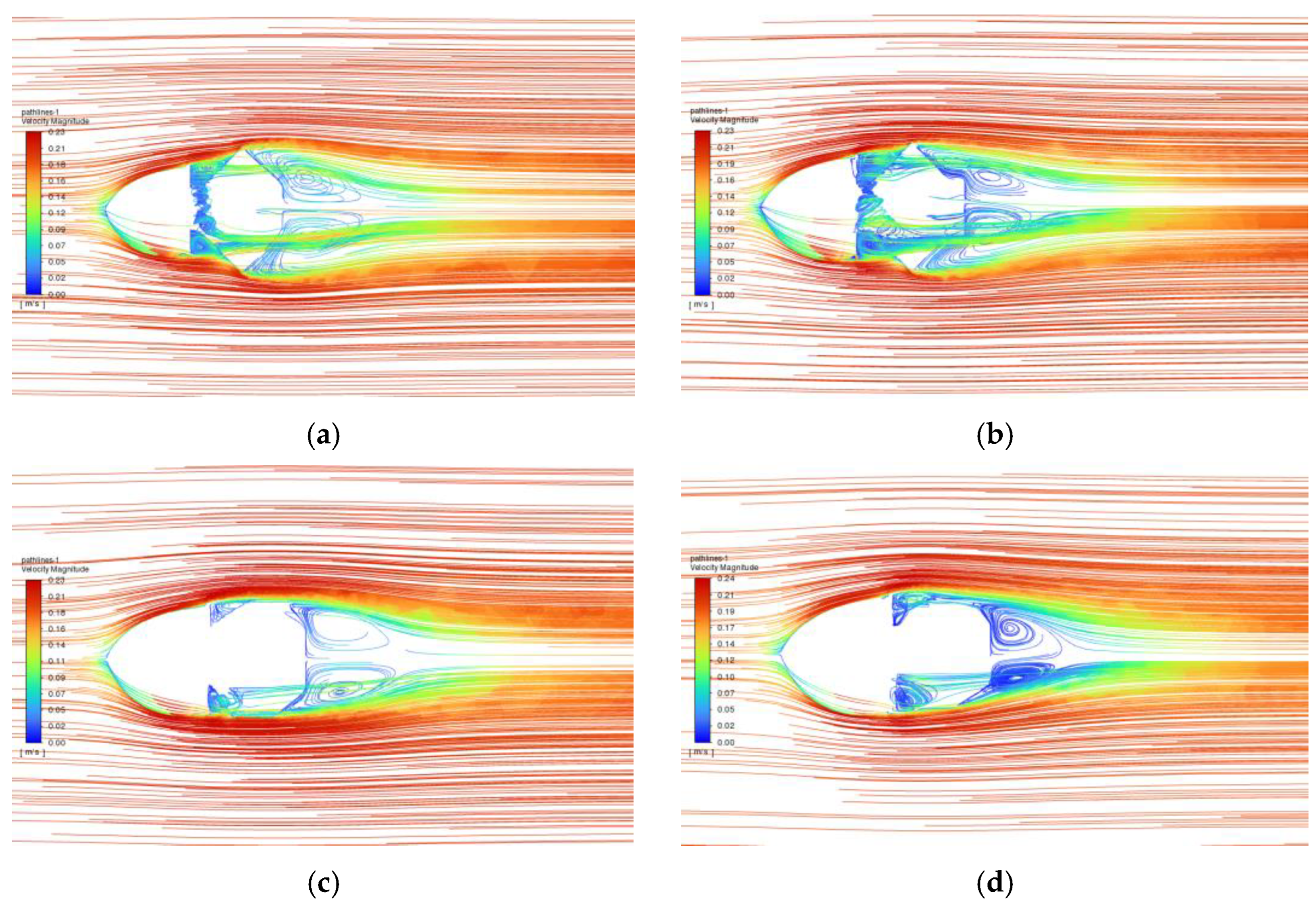
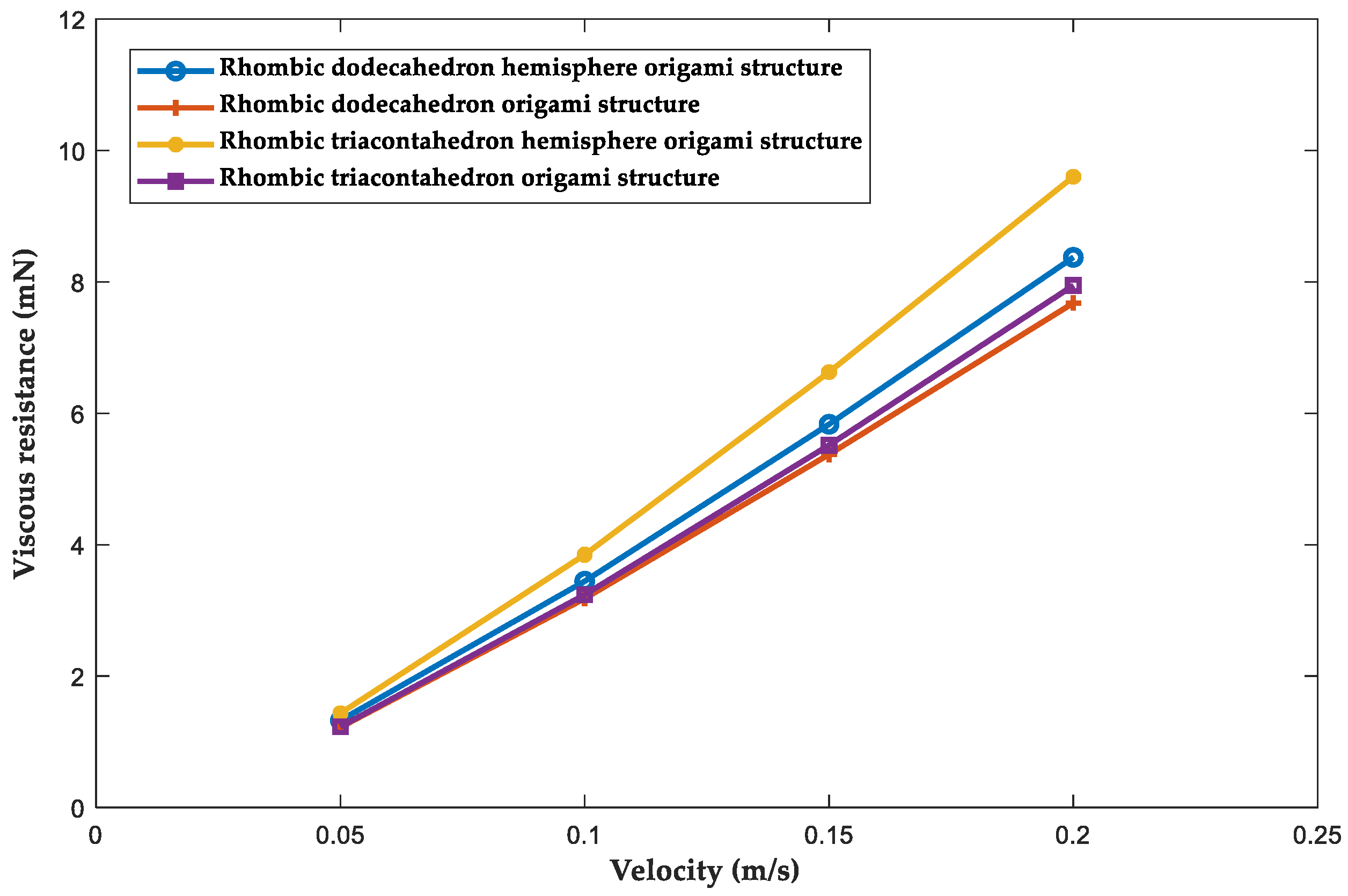
3.2. Resistance Analysis

Considering that the bell form strongly affects the hydrodynamic performance of jellyfish-like swimmers, the effects of four origami variants on the hydrodynamic variables should be investigated. To facilitate the comparison, the four origami variants are supposed to have the same volume, that is, the volumes of water discharged during a single contraction are equal. Therefore, the thrust of the bionic jellyfish robot is merely related to the diameter of the nozzle and the contraction speed at the same volume of the inner cavity. Further according to the resistance of the bionic jellyfish robot structure and the swimming steady state, the best origami variant can be deduced.
Considering the practical application and production feasibility of bionic jellyfish, take L 4 = 20   mm preliminarily, then V 4 98 , 485.60   mm 3 . Further, let V 1 = V 2 = V 3 = V 4 , and we get L 2 31.74   mm , L 1   39.99   mm , L 3 25 , .20   mm . The head of the bionic jellyfish robot is designed to be streamlined to reduce the resistance during swimming, and it also serves as a closed box to hold the motor.
The resistance during the jellyfish robot cruising determines its swimming speed and efficiency. The resistance direction is opposite to the forward direction of the bionic jellyfish robot, and the resistance can be calculated by:
F d = 1 2 ρ v 2 SC d
where ρ is the fluid density. v is the forward speed of the bionic jellyfish robot. S is the cross-section of the bionic jellyfish robot. C d is the resistance coefficient.
To measure the ratio relationship between differential pressure and viscous resistance during the swimming of bionic jellyfish, the Reynolds number is introduced,
Re = vd γ
where v is the swimming speed of the bionic jellyfish robot relative to the surrounding fluid, d is the length of the bionic jellyfish robot, and γ is the kinematic viscosity (kinematic viscosity of water at 20   ° C is γ = 1.007 × 10 6   m 2 / s ) .
Past studies have shown that during biological swimming, when the Reynolds number Re < 1 , the Reynolds number is small, and the biological swimming resistance mainly comes from viscous resistance. When the Reynolds number Re > 1000 , the Reynolds number is large, thus the biological swimming resistance mainly originates from the differential pressure resistance. If 1 < Re < 1000 , both viscous resistance and differential pressure resistance need to be considered. The designed bionic jellyfish robot d 0.25   m , Re 2482.62 at 0.01   m / s swimming speed and Re 49 , 652.43 at 0.2   m / s swimming speed, which indicates that the resistance during the swimming of the origami flexiball inspired jellyfish robot mainly comes from the differential pressure resistance, and the viscous resistance can be ignored, no matter at low or high speed.
Four bionic jellyfish robots with the given four origami variants and the uniform streamlined shell head were simulated by fluid simulation software at different background flow rates. Figure 2 presents the path lines of the bionic jellyfish robot with the given four origami variants at 0.2   m / s . Figure 3 compares the differential pressure resistance of the given four origami variants at different swimming speeds. Figure 4 compares the viscous resistance of the given four origami variants at different swimming speeds. Further, Figure 5 displays the contrastive sum of pressure resistance and viscous resistance.
The simulation results show that the rhombic dodecahedral hemisphere origami flexiball, and the rhombic dodecahedron origami flexiball generate many vortices around the structure that are not conducive to the swimming of the bionic jellyfish robot due to the shape because the collision of these vortices greatly accelerates energy dissipation from each of the participating vortices. In contrast, the rhombic triacontahedron hemisphere structure and the rhombic triacontahedron structure generate smaller vortices around the structures.
The differential pressure resistance of the four different origami flexiball structures varied greatly at different swimming speeds, whereas the rhombic triacontahedron origami flexiball structure exhibited relatively low resistance at high swimming speeds. The viscous resistance of four origami flexiball structures in swimming did not seriously change at different swimming speeds, which is consistent with the theoretical analysis.

3.3. Lift Analysis

When the origami flexiball-inspired bionic jellyfish robot is cruising, the difference in fluid flow velocity distributed on the upper and lower surfaces causes the pressure difference. According to Bernoulli’s law, the lift force can be calculated by:
F L = 1 2 ρ v 2 SC L
where C L is the lift coefficient. The change trend between lift and swimming speed of different origami structures is illustrated in Figure 6.
The simulation results show that, besides the rhombic dodecahedron origami flexiball, the other three origami structures exhibit positive lift characteristics. The rhombic dodecahedron origami structure has a negative lift force at high swimming speed, which indicates that it will need extra buoyancy when swimming. This point is not conducive to the swimming of the bionic jellyfish robot.

3.4. Model Selection

In order to evaluate the effects of different origami structures on the swimming performance of the bionic jellyfish robot, the lift-to-resistance ratio was introduced. The lift-drag ratio can be expressed as:
F L F d = 1 2 ρ v 2 SC L 1 2 ρ v 2 SC d
Generally, the cross-sectional area used to calculate the resistance and lift are the same; hence, the lift-drag ratio can be simplified as the ratio of the lift coefficient to the resistance coefficient,
F L F d = C L C d
The ratio is related to the angle of attack, swimming speed, and other parameters of the bionic jellyfish robot. The larger the ratio, the greater the lift force would be with the same resistance. That is, the larger the lift–drag ratio is, the better the hydrodynamic performance of the bionic jellyfish robot.
The relationship between the lift–drag ratio and the swimming speed of different origami structures is illustrated in Figure 7.
To sum up, the four origami flexiball structures provided less lift during underwater motion and did not change much with the increase of swimming speed. The four origami flexiball structures showed different trends of lift to resistance ratio at different swimming speeds. Only the rhombic triacontahedral origami flexiball structure showed a stable increase of the lift-drag ratio vs. the increasing swimming speed. Moreover, the values were always positive, which was beneficial to the stable swimming of the bionic jellyfish robot. In this regard, the rhombic triacontahedral origami flexiball was selected as the propulsion structure for the bionic jellyfish robot after considering the resistance and lift-drag ratios of the four origami sphere structures under different background flow velocities.

4. Jet Propulsion Performance

4.1. Jet Propulsion Modelling

The origami flexiball inspired bionic jellyfish robot draws fluid into the origami structure by expansion, and then accelerates the fluid within the structure by contraction to eject it. Due to the rapid change in the pressure gradient of the flow field, a centrosymmetric vortex ring is formed in the flow field. The bionic jellyfish robot relies on periodic expansion and contraction motions to periodically eject the fluid into the flow field, thereby gaining thrust.
As with other devices that rely on jet propulsion, the thrust force generated during the jet propulsion of the bionic jellyfish robot can be derived from the Theorem of Momentum and the Law of Conservation of Momentum. Let the velocity of the fluid at the nozzle of the bionic jellyfish robot at a certain moment t be v p , and the nozzle has a circle radius r p (Figure 8), then the thrust force can be expressed by:
F T = dm s dt v p = C S d ρ f π r p 2 L l dt v p = C s ρ f π r p 2 v p 2
where m s is the total mass of the ejected fluid, and L l is the total length of the ejected fluid. C S is a factor of less than 1 to represent the loss of fluid energy at the nozzle, and ρ f is the density of the fluid.
From the above formula, we can learn that the magnitude of the thrust force is mainly related to the jet velocity and nozzle radius. In general, the fluid velocity at the nozzle is not easy to measure. If we can measure the rate of change of the shrinkage volume of the origami flexiball structure, we can calculate the jet speed. The relationship between the rate of change of volume of the origami flexiball structure and the fluid velocity at the nozzle is:
v p = dV dt C s π r p 2
Assuming that the length of the edges of the rhombic triacontahedral origami structure is L , the radius of the midradius (touches the middle of each edge) of the rhombic triacontahedral origami structure is:
r m = 1 + 1 5 L 1.44721 L
The volume of this mid-cross sphere is:
V m = 4 3 π r m 3 12.6965 L 3
The formula has similarity with the volume calculation formula of rhombic triacontahedral origami structure, so the rhombic triacontahedral origami structure can be approximated as a sphere in its released state (Figure 9).
In the contraction of the rhombic triacontahedron origami flexiball structure, let the radius in the X, Y, Z three directions are b, a, c, when a = b = c, the origami flexiball structure can be viewed as a sphere. If its structure along the Y axis basically does not contract, while the structure only along the X, Z axis is contracted, then the contraction value is equal, during this period a > b = c, the flexiball structure can be viewed as an ellipsoid. During the expansion process, the origami flexiball structure basically does not expand along the Y axis, thus the structure only expands along the X and Z axis, moreover the expansion amount is also equal.
As an ideal of mathematical analysis, the change rate of the origami flexiball volume with time is:
dV t = 8 3 π R 1 R t R t dt = 8 3 π R 1 v R 1 vt dt
where R t is the radius of the origami flexiball at moment t . R 1 is the initial radius of the origami flexiball structure. v is the contraction speed of the radius of the origami flexiball cross-section.
Assume that there is no energy loss in the process of water injection, ignore the viscosity and boundary layer effect, and that the cross-section of the nozzle fluid velocity is the same, then the velocity of the fluid at the nozzle is:
v p t = dV dt C s π r p 2 = dV t π r p 2 dt = 8 R 1 v R 1 vt 3 r p 2
where r p is the radius of the nozzle. Neglecting the energy loss at the nozzle, C s = 1 , substituting the previous nozzle propulsion equation (Equation (6)) yields:
F T = C s ρ f π r p 2 v p 2 = 64 π ρ f R 1 2 v 2 R 1 vt 2 9 r p 2

4.2. Jet Propulsion Simulation

To investigate the propulsion performance of the origami flexiball inspired bionic jellyfish robot with different nozzle diameters. We assume the structure utilization rate η = 66.6 % for the origami flexiball structure, considering that, in practice, the fluid cannot completely fill the origami flexiball structure when the bionic jellyfish robot is stretched. It is also impossible to completely exhaust the fluid inside the structure when the origami flexiball structure is contracted. That is, the discharge capacity V P = η × V 4 = 65 , 657.0667   mm 3 .
The initial radius R 1 of the rhombic triacontahedral origami flexiball structure and the time t required to contract are set to constant values. The origami flexiball radius contraction velocity v is set to a sine function, that is, v = Csin wt , then the nozzle ejected fluid velocity can be calculated by:
v p t = 8 R 1 Csin wt R 1 tCsin wt 3 r p 2
The first wave of the velocity function of the ejected fluid from this nozzle can be approximated as the first half-cycle of the sine function, so the velocity outlet velocity function in the simulation can be approximated as the first half-cycle of the sine function.
To investigate the propulsion efficiency of the origami flexiball bionic jellyfish robot under different nozzle diameters, three different diameters of nozzle were discussed: 15   mm ,   20   mm ,   and   25   mm . Single contraction time t 1 = 1.5   s . The fitted sine function of fluid velocity at the nozzle was set as:
v s = Hsin 2 π 3 t
Let,
v p = vCt = C 0 t 1 v s dt = CH 0 1.5 sin 2 π 3 t dt
The velocity fitting functions for the fluid at the three diameter nozzles were solved (Table 1).
The nozzle injection process is a transient fluid simulation, in which the model is selected as LES (large eddy simulation). The inlet is set as velocity inlet, and the outlet is set as pressure outlet. The nozzle fluid velocity of the bionic jellyfish robot with three different nozzle diameters in the simulation is set to the fluid velocity fitting function in the Table 1. The background velocity is set to 0, similar to fixing the model for simulation, that is, the simulation merely simulates the jetting process of the bionic jellyfish robot. Figure 10, Figure 11 and Figure 12 show the velocity nephograms and vorticity maps in the flow field during the jetting process, respectively.
From the vector and vortex diagrams, it can be seen that as the diameter of the nozzle increases, the more the volume of fluid ejected from the nozzle at 0–2 s, but the velocity becomes lower, and the size and strength of the vortex ring are reduced. At the beginning of the jet, a thin boundary layer is formed on the wall of the nozzle due to the high velocity flow of the water, and there is a large velocity gradient inside it. Vortex rings exist everywhere inside the nozzle, but they are not obvious in the vorticity map due to the small scale. The vortices at the edges of the nozzle are shed due to the large negative pressure gradient and rotate backward with the external fluid, thus forming vortex rings. There are several inconspicuous trailing vortices after the main vortex ring. As the jetting process proceeds, the size and strength of the main vortex ring gradually increases and moves backward with the jet. The jetting process ends after t = 2   s , and the main vortex ring falls off, forming a stable vortex ring.
The pressure at the nozzle is integrated to obtain the time-varying curve of the thrust force at different nozzle diameters (Figure 13).
From the Figure 13, it can be concluded that the thrust force produced by different nozzles increases rapidly to a maximum value and decreases slowly to 0. As the nozzle diameter increases, the peak thrust force increases, but the duration decreases. The integral I of the thrust force over time is used to measure the propulsive effect of a single jet at different nozzle diameters,
I = Fdt
Here we use the jet length A and vortex ring core diameter B to describe the strength of the vortex ring generated by the jetting process at different nozzle diameters (Figure 14).
In the simulation, three different nozzle diameters of the bionic jellyfish robot ejected the same volume of water at the same time. The smaller nozzle diameter means that the velocity of the ejected fluid is higher, that is, the smaller nozzle requires more energy to complete an ejection process, that is, the energy utilization efficiency of the smaller diameter nozzle is lower. To measure the swimming efficiency of the bionic jellyfish robot, the vortex ring formation number was introduced,
L v D = 0 t v p t dt 2 r p
The jet length, vortex ring core diameter, total impulse, and vortex ring formation numbers for a single jetting process with three different nozzle diameters are shown in Table 2.
As the diameter of the bionic jellyfish robot nozzle increases, the jet length is rapidly smaller, but the vortex ring core diameter increases. This indicates that within a certain range, the smaller the size of the nozzle, although the short time vortex ring strength is not as strong as the larger size nozzle, the jet speed and persistence are better than the larger size nozzle.
The impulse of the combined external force on the bionic jellyfish robot is equal to the increment of its momentum, so the total impulse can reflect the amount of change in momentum during a single jet at different nozzle diameters. The value of the vortex ring formation number determines the vortex ring pattern of the nozzle jet. The flow field generated by a large vortex ring formation number is composed of a leading vortex ring and a trailing jet, and the vortex field of the leading vortex ring is separated from the vortex field of the trailing jet. In contrast, the flow field generated by a small vortex ring formation number will have only one vortex ring. The vortex ring formation number at the critical point of these two states is about 4. The maximum circulation reached in the formation of the vortex ring is attained at this vortex ring formation number. This suggests that the closer the vortex formation number is to this critical value, the more efficient the jet propulsion is.
The total impulse provided by the single jetting process at the three nozzle diameters increases as the nozzle diameter of the bionic jellyfish robot decreases. The vortex ring formation numbers for all three nozzle diameters have values greater than the critical value of 4, which indicates that several trailing vortices will exist after the main vortex ring in all three cases after jetting, and the strength and size of the main vortex ring continue to increase as the jetting process continues and gradually moves forward to form a stable vortex ring. The generated vortex rings will increase the propulsive performance of the bionic jellyfish robot to some extent.
The jet propulsion efficiency of the bionic jellyfish robot decreases as the nozzle diameter decreases, but the jet process is mainly to generate propulsion for forward motion. Large thrust force is more important than propulsion efficiency, so the vortex ring formation number is generally higher in practice. In order to obtain higher motion performance, a 15   mm diameter nozzle is chosen to make the bionic jellyfish robot in kind, after which a larger diameter nozzle can be used if high efficiency propulsion of the bionic jellyfish robot is required.

5. Prototype of Robotic Jellyfish

5.1. Overall Structure

Figure 15 shows the designed origami flexiball-inspired bionic jellyfish robot. The structure of the origami flexiball is made of thermoplastic polyurethanes (TPU) material. The rest of the connecting parts and the shell are printed with polylactic acid (PLA) material, and the connecting parts are sealed with waterproof adhesive.
Three driving ropes are wound in the grooves of the rhombic triacontahedral origami structure in the manner of Figure 16. The surface of the origami flexiball structure is covered with a rubber film that can shrink and stretch with the origami flexiball, and the head and tail of the origami structure have a fixer for fixing the origami structure. The fixer and the rubber film together form a deformable cavity with the origami ball. By rotating the MG996R servo inside the enclosure, the middle low driving rope is shortened, which in turn drives the remaining two driving ropes to tighten, causing the radius of the origami flexiball structure to shrink, reducing the volume of the cavity and ejecting water from the nozzle. In the relaxation process, the servo reverses the release of driving rope, and the rhombic triacontahedron origami flexiball structure relying on the elasticity of its own structure returns to the relaxed state. Meanwhile the cavity volume increases, and the nozzle slowly absorbs water.

5.2. Prototype

Figure 17 shows the finalized prototype of the origami flexiball inspired bionic jellyfish robot. In the two distinct states, the diameters of the origami flexiball are 70   mm in the released state on the left and 50   mm in the contracted state.
The origami flexiball-inspired bionic jellyfish robot has 225.9   g and a volume of 243.62   cm 3 and provides a buoyancy of about 2387.48   mN when fully submerged in water. When fully submerged in water, the buoyancy of the bionic jellyfish robot itself is greater than gravity, which will help improve the cruising performance of the bionic jellyfish. The servo is controlled and driven by the Arduino control board. The maximum torque of the servo is 13   kg / cm . Its speed is 0.16   s / 60 ° (at 5 V) without load, and the contraction speed is 0.5   s / 60 ° (at 5 V) after full stretch. It takes 1.5   s to complete a single contraction in water at the fastest. When the bionic jellyfish robot origami structure shrinks, the ellipsoidal semiaxis shrinks by 10   mm , and the single shrinkage water displacement is 165.88   cm 3 . The actual volume change rate is 48.98 % at maximum range.

5.3. Control Method

The motion of the bionic jellyfish is divided into four stages by controlling the servo through the Arduino control board. In the contraction phase ( T 1 = 1.5   s ), the origami flexiball structure contracts, and the bionic jellyfish robot jets water to accelerate. In the cruise phase ( T 2 = 0.5   s ), the origami flexiball structure remains unchanged, the volume is minimized, and the bionic jellyfish robot relies on inertia to advance, and the jellyfish is subject to minimal water resistance at this time. In the relaxation phase ( T 3 = 1.8   s ), the origami flexiball structure slowly expands and absorbs water, and the volume increases at this time, and the bionic jellyfish robot slows down and advances. In the waiting phase ( T 4 = 0.2   s ), the origami flexiball structure remains unchanged and the volume is maximized to prepare for the next contraction, and the bionic jellyfish robot completes one cycle of motion.

6. Experiments

6.1. Experimental Platform

A camera (SONY IMX682,made by Sony Corporation in Wuxi City of China) was mounted 0.2   m above the center of the water tank 80   mm × 45   mm × 45   mm to track the trajectory of the bionic jellyfish robot (Figure 18). A graph sheet was placed at the bottom of the tank with a 10   mm edge length to simplify the tracking process and eliminate the effect of image distortion caused by the camera. The developed bionic jellyfish robot floats in the water, and the nozzle at the back end is completely immersed in the water by adding weight to make the bionic jellyfish robot completely immersed in the water. In the propulsion experiment, the bionic jellyfish robot is fixed to one end of the cantilevered force sensing by a fixed frame, and the other end of the sensor is fixed in the water tank by a fixed frame.

6.2. Measurement of Propulsive Force

We also measured the propulsive force generated by the bionic jellyfish robot over several jetting cycles through the experimental platform (Figure 19).
It can be seen from the table that during the contraction phase, the propulsive force generated by the bionic jellyfish robot increases rapidly and reaches a maximum value of 35.2   mN around 0.4   s , and then the generated propulsive force decreases slowly; during the cruise phase, the propulsive force is small and does not change much; during the diastole phase, the bionic jellyfish robot is subjected to negative propulsion due to water absorption, and its change trend also increases rapidly first and reaches a negative value of 4.4   mN around 2.1   s . The maximum value is 4.4   mN , and decreases slowly afterwards, and finally the thrust force is 0 during the waiting phase.
The actual propulsion results can better reflect the previous propulsion simulation results, but there are still errors, presumably due to the actual water absorption. Water jetting efficiency is lower than the theoretical value, as well as in the simulation and did not simulate the water absorption process.

6.3. Jet Swimming

In order to verify the movement results and propulsion performance of the developed bionic jellyfish robot, it was tested on the constructed experimental platform (Figure 20). The obtained videos were processed, and it was concluded that the bionic jellyfish robot completed a total of six action cycles in 26   s , advancing a total of 301.0   mm , with an average single action cycle advancing 50.2   mm , accounting for 20.2 % of the whole body length, and an average speed of 11.58   mm / s .

6.4. Strouhal Number

An important dimensionless quantity for assessing the swimming performance of aquatic organisms is the Strouhal number [25], which is calculated by:
St = f A U
where f is the frequency of motion, A is the amplitude, and U is the velocity of forward motion. For the origami flexiball-inspired bionic jellyfish robot, the amplitude is the amplitude of the contraction and stretching of the radius of the origami flexiball structure.
In nature, most aquatic organisms, such as dolphins, sharks, and squid, have a Strouhal number between 0.2 < S t < 0.4 . It has been experimentally demonstrated that the propulsion efficiency of aquatic organisms is higher in that range. After calculation, the Strouhal number of our developed origami flexiball-inspired bionic jellyfish robot prototype is 0.2159, which indicates that the propulsion efficiency of our developed origami flexiball-inspired bionic jellyfish robot is high.

6.5. Cost of Transport

We also tested the power consumption of the origami flexiball-inspired bionic jellyfish robot with a dedicated power measurement module. Due to the poor consistency of the power variation of the origami flexiball-inspired bionic jellyfish robot in the early start-up period, we measured the power variation curve of the origami flexiball-inspired bionic jellyfish robot after three to four cycles of running for four cycles, as shown in Figure 21.
The first peak of the power of the origami flexiball-inspired bionic jellyfish robot is the contraction phase. During the cruise phase the servo motor is in standby and the power is approximately equal to 0. The second power peak is the relaxation phase, which lasts for a longer period of time. Then the power returns to standby power and enters a short waiting phase. This completes one cycle, and it can be seen from the graph that the power variation is consistent over the four cycles.
We integrate the area under the power curve to obtain an average energy consumption of 2.19 J for the origami flexiball-inspired bionic jellyfish robot over one drive cycle.
To evaluate the energy use efficiency of the origami flexiball-inspired bionic jellyfish robot, the cost of transport ( COT ) calculation formula is introduced [26],
COT = E mgS
where E is the energy consumed by the origami flexiball-inspired bionic jellyfish robot in a single action cycle, m is the mass of the origami flexiball-inspired bionic jellyfish robot, g is the acceleration of gravity ( 9.8   m / s 2 ), and S is the forward distance of the origami flexiball-inspired bionic jellyfish robot in a single action. The cost of transport of our prototype origami flexiball-inspired bionic jellyfish robot is calculated to be 19.02. This value is slightly higher than that of the same type of bionic jellyfish robot [27], but lower than that of the same type of rope-driven bionic robot [28,29].
We argue that the higher COT value is mainly due to the fact that the driving rope is still elastic, and the designed multiple driving rope transmission structure loses a lot of energy. In addition, the deformation of the origami flexiball structure also loses some energy, and all of these will lead to the high COT of the origami flexiball-inspired bionic jellyfish robot.

7. Prospective Directions

Underwater robots that imitate the swimming principles, morphologies, and softness of aquatic animals are useful for exploring valuable resources and marine life [30]. If the presented origami flexiball-inspired soft robotic jellyfish is empowered with the related sensors, it would be a promising schema for the ecological aquatic phenomena monitoring and data collection, because that it has many advantages including but not limited to concise structure, low cost, and ease of manufacture. Admittedly, the current project is now at the embryonal stage of real applications, hence we’ve still got a long way ahead of us [31]. The prospective directions would cover the following aspects.

7.1. Maneuverability

Albeit the presented robotic jellyfish is basically able to mimic the jet-propelled swimming behavior of the prolate medusae, it manifests a poor maneuverability, that is, it lacks steerability and adjustable buoyancy for floating and sinking. The critical reason is that we have not completely simulated the swimming behavior of jellyfish. Besides the jet propulsion mode, the bell shape of jellyfish can produce a combination of vortex, jet propulsion, rowing, and suction-based locomotion [32,33]. Jellyfish can also turn via an asymmetric contraction of the body. Therefore, future work will seek the suitable smart soft actuators to imitate the natural jellyfish kinematics through more complex controllable deformations [34]. As reviewed above, the optional major categories of smart actuators include SMA, electroactive polymer (EAP), piezoelectric actuators (PZT), and fluid elastomer actuator (FEA) [35].

7.2. Perception

As mentioned above, during the swimming of jellyfish, the exchange of momentum from the jellyfish body to water and vice versa introduces a thrust on the jellyfish body resulting in motion. Hence, it is very important to sense the dynamics and properties of water by multi-sensors such depth meter, water sensor, pressure sensor, and leak sensor. The artificial lateral line (ALL) sensor provides a novel approach to underwater flow sensing, whereas ALL systems help to detect underwater hydrodynamic stimuli and navigate the swimming autonomously [36]. Furthermore, the proprioceptive sensing of soft-bodied deformation is conductive to control the interaction of the morphology with the with the environment [37]. Therefore, the flex sensor, optical fiber sensors, or even the specially designed sensing structure are considered to be integrated into the soft body. Certainly, the global information perception is also very important for the control and motion planning of the robotic jellyfish, normally which are provided by the compass, camera, accelerometer, and so forth [38,39].

7.3. Structure Improvement

In this study, the structure of origami polyhedra is merely introduced to approximate the jet propulsion mode of jellyfish. The improvement room of the current schema is highly open. Indeed, if the on-demand deployable and collapsible umbrella-like origami structure [40] is coupled into the existing model, it is promising to generate comprehensive behaviors of the prolate medusae as well as the oblate medusae, for example, floating and complex locomotion styles. Additionally, for more potential applications, the origami model that has the grasping functionality also is proposed to be integrated with the existing schema.

8. Conclusions

This work is demonstrated a novel robotic swimmer by introducing the origami flexiball to mimic the jellyfish-like jet-propelled swimming. The theoretical and simulation analysis fit well with the experimental results, providing a scientific argument to translate the conceptual design into a real prototype. As an experimental result, the origami flexiball-inspired soft robotic jellyfish can swim at an average speed of 11.58   mm / s . Concluding, the presented robotic jellyfish has the following advantages:
  • Easy-to-manufacture. The 3D printing method with the accessible soft elastic materials enables the robotic jellyfish to be fabricated rapidly and at low cost;
  • Structural simplicity. The overall structure has no complex parts, and no complicated assembly or die preparation is required;
  • Good scalability. The geometric dimensions and the structural elasticity are programmable, and the rope-motor-driving method also has good adaptability to the variants.
Admittedly, as mentioned in the prospective directions for further research, the current project has lots of room for improvement, in particular, in terms of perception and maneuverability. More refined research further could aim at the delicate imitation from the swimming behavior to morphological adaptability, as well as applicable development.

Author Contributions

Conceptualization, F.H.; methodology, F.H.; software, Z.K.; validation, F.H. and Z.K.; formal analysis, Z.K.; investigation, Z.K.; resources, F.H.; data curation, Z.K.; writing—original draft preparation, Z.K., F.H., E.M.S. and T.M.; writing—review and editing, F.H., E.M.S. and T.M.; Visualization, Z.K., F.H., E.M.S. and T.M.; supervision, F.H.; project administration, F.H.; funding acquisition, F.H. All authors have read and agreed to the published version of the manuscript.

Funding

The project was supported by the Cooperation Project between Industry and University approved by the Ministry of Education of China (No. 202002148005).

Institutional Review Board Statement

Not applicable.

Informed Consent Statement

Not applicable.

Data Availability Statement

All data generated or analyzed during this study are included in this article.

Conflicts of Interest

The authors declare no conflict of interest.

Nomenclature

ALLArtificial Lateral Line
BCFBody and/or Caudal Fin
COTCost of Transport
DEADielectric Elastomer Actuators
DIPDirect Inkjet Printing
EAPElectroactive Polymer
FDMFused Deposition Modeling
FEAFluid Elastomer Actuator
LESLarge Eddy Simulation
MPFMedian and/or Paired Fin
PLAPolylactic Acid
PZTPiezoelectric Actuators
SLAStereo Lithography Apparatus
SMAShape-Memory Alloy
TPUThermoplastic Polyurethanes

References

  1. Hu, F.; Wang, W.; Cheng, J.; Bao, Y. Origami spring–inspired metamaterials and robots: An attempt at fully programmable robotics. Sci. Prog. 2020, 103, 0036850420946162. [Google Scholar] [CrossRef]
  2. Hu, F.; Cheng, J.; He, Y. Interactive design for additive manufacturing: A creative case of synchronous belt drive. Int. J. Interact. Des. Manuf. (IJIDeM) 2018, 12, 889–901. [Google Scholar]
  3. Rafsanjani, A.; Zhang, Y.; Liu, B.; Rubinstein, S.M.; Bertoldi, K. Kirigami skins make a simple soft actuator crawl. Sci. Robot. 2018, 3, eaar7555. [Google Scholar] [CrossRef] [PubMed] [Green Version]
  4. Kim, Y.; Lee, Y.; Cha, Y. Origami pump actuator based pneumatic quadruped robot (OPARO). IEEE Access 2021, 9, 41010–41018. [Google Scholar] [CrossRef]
  5. Yang, Z.; Chen, D.; Levine, D.J.; Sung, C. Origami-inspired robot that swims via jet propulsion. IEEE Robot. Autom. Lett. 2021, 6, 7145–7152. [Google Scholar] [CrossRef]
  6. Lee, D.Y.; Kim, S.R.; Kim, J.S.; Park, J.J.; Cho, K.J. Origami wheel transformer: A variable-diameter wheel drive robot using an origami structure. Soft Robot. 2017, 4, 163–180. [Google Scholar] [CrossRef] [PubMed]
  7. Chen, Z.; Tighe, B.; Zhao, J. Origami-Inspired Modules Enable A Reconfigurable Robot with Programmable Shapes and Motions. IEEE/ASME Trans. Mechatron. 2022, 27, 2016–2025. [Google Scholar] [CrossRef]
  8. Hu, F.; Li, T. An origami flexiball-inspired metamaterial actuator and its in-pipe robot prototype. Actuators 2021, 10, 67. [Google Scholar] [CrossRef]
  9. Blasiak, R.; Jouffray, J.B.; Amon, D.J.; Moberg, F.; Claudet, J.; Jørgensen, P.S.; Pranindita, A.; Wabnitz, C.C.C.; Österblom, H. A forgotten element of the blue economy: Marine biomimetics and inspiration from the deep sea. PNAS Nexus 2022, 1, pgac196. [Google Scholar] [CrossRef]
  10. Colin, S.P.; Costello, J.H.; Dabiri, J.O.; Villanueva, A.; Blottman, J.B.; Gemmell, B.J.; Priya, S. Biomimetic and live medusae reveal the mechanistic advantages of a flexible bell margin. PLoS ONE 2012, 7, e48909. [Google Scholar] [CrossRef] [Green Version]
  11. Colin, S.P.; Costello, J.H. Morphology, swimming performance and propulsive mode of six co-occurring hydromedusae. J. Exp. Biol. 2002, 205, 427–437. [Google Scholar] [CrossRef]
  12. Zuo, W.; Dhal, K.; Keow, A.; Chakravarthy, A.; Chen, Z. Model-based control of a robotic fish to enable 3d maneuvering through a moving orifice. IEEE Robot. Autom. Lett. 2020, 5, 4719–4726. [Google Scholar] [CrossRef]
  13. Ford, M.D.; Costello, J.H. Kinematic comparison of bell contraction by four species of hydromedusae. Sci. Mar. 2000, 64, 47–53. [Google Scholar]
  14. Chen, F.; Wang, M.Y. Design optimization of soft robots: A review of the state of the art. IEEE Robot. Autom. Mag. 2020, 27, 27–43. [Google Scholar] [CrossRef]
  15. Ulloa, C.C.; Terrile, S.; Barrientos, A. Soft underwater robot actuated by shape-memory alloys “Jellyrobcib” for path tracking through fuzzy visual control. Appl. Sci. 2020, 10, 7160. [Google Scholar] [CrossRef]
  16. Almubarak, Y.; Punnoose, M.; Maly, N.X.; Hamidi, A.; Tadesse, Y. KryptoJelly: A jellyfish robot with confined, adjustable pre-stress, and easily replaceable shape memory alloy NiTi actuators. Smart Mater. Struct. 2020, 29, 075011. [Google Scholar] [CrossRef]
  17. Zhou, Y.; Jin, H.; Liu, C.; Dong, E.; Xu, M.; Yang, J. A novel biomimetic jellyfish robot based on a soft and smart modular structure (SMS). In Proceedings of the 2016 IEEE International Conference on Robotics and Biomimetics (ROBIO), Qingdao, China, 3–7 December 2016; pp. 708–713. [Google Scholar]
  18. Yang, Y.; Ye, X.; Guo, S. A new type of jellyfish-like microrobot. In Proceedings of the 2007 IEEE International Conference on Integration Technology, Shenzhen, China, 20–24 March 2007; pp. 673–678. [Google Scholar]
  19. Ko, Y.; Na, S.; Lee, Y.; Cha, K.; Ko, S.Y.; Park, J.; Park, S. A jellyfish-like swimming mini-robot actuated by an electromagnetic actuation system. Smart Mater. Struct. 2012, 21, 057001. [Google Scholar] [CrossRef]
  20. Ren, Z.; Hu, W.; Dong, X.; Sitti, M. Multi-functional soft-bodied jellyfish-like swimming. Nat. Commun. 2019, 10, 2703. [Google Scholar] [CrossRef] [PubMed] [Green Version]
  21. Shintake, J.; Shea, H.; Floreano, D. Biomimetic underwater robots based on dielectric elastomer actuators. In Proceedings of the 2016 IEEE/RSJ International Conference on Intelligent Robots and Systems (IROS), Daejeon, Republic of Korea, 9–14 October 2016; pp. 4957–4962. [Google Scholar]
  22. Cheng, T.; Li, G.; Liang, Y.; Zhang, M.; Liu, B.; Wong, T.-W.; Forman, J.; Chen, M.; Wang, G.; Tao, Y. Untethered soft robotic jellyfish. Smart Mater. Struct. 2018, 28, 015019. [Google Scholar] [CrossRef]
  23. Frame, J.; Lopez, N.; Curet, O.; Engeberg, E.D. Thrust force characterization of free-swimming soft robotic jellyfish. Bioinspiration Biomim. 2018, 13, 064001. [Google Scholar] [CrossRef]
  24. Yu, J.; Tan, M. Motion Control of Self-propelled Robotic Jellyfish. In Motion Control of Biomimetic Swimming Robots; Springer: Singapore, 2020; pp. 173–196. [Google Scholar]
  25. Zhong, Y.; Li, Z.; Du, R. A novel robot fish with wire-driven active body and compliant tail. IEEE/ASME Trans. Mechatron. 2017, 22, 1633–1643. [Google Scholar] [CrossRef]
  26. Zhu, J.; White, C.; Wainwright, D.K.; Di Santo, V.; Lauder, G.V.; Bart-Smith, H. Tuna robotics: A high-frequency experimental platform exploring the performance space of swimming fishes. Sci. Robot. 2019, 4, eaax4615. [Google Scholar] [CrossRef] [PubMed]
  27. Gemmell, B.J.; Dabiri, J.O.; Colin, S.P.; Costello, J.H.; Townsend, J.P.; Sutherland, K.R. Cool your jets: Biological jet propulsion in marine invertebrates. J. Exp. Biol. 2021, 224, jeb222083. [Google Scholar] [CrossRef] [PubMed]
  28. Low, K.H.; Chong, C.W.; Zhou, C. Performance study of a fish robot propelled by a flexible caudal fin. In Proceedings of the 2010 IEEE International Conference on Robotics and Automation, Anchorage, AK, USA, 3–7 May 2010; pp. 90–95. [Google Scholar]
  29. Romano, D.; Wahi, A.; Miraglia, M.; Stefanini, C. Development of a novel underactuated robotic fish with magnetic transmission system. Machines 2022, 10, 755. [Google Scholar] [CrossRef]
  30. Hernández-Jaramillo, D.C.; Vásquez, R.E. Design of a Bioinspired Underwater Glider for Oceanographic Research. Biomimetics 2023, 8, 80. [Google Scholar] [CrossRef]
  31. Masoomi, S.; Gutschmidt, S.; Chen, X.; Sellier, M. The kinematics and dynamics of undulatory motion of a tuna-mimetic robot. Int. J. Adv. Robot. Syst. 2015, 17, 83. [Google Scholar] [CrossRef] [Green Version]
  32. Dabiri, J.O.; Colin, S.P.; Costello, J.H.; Gharib, M. Flow patterns generated by oblate medusan jellyfish: Field measurements and laboratory analyses. J. Exp. Biol. 2005, 208, 1257–1265. [Google Scholar] [CrossRef] [PubMed] [Green Version]
  33. Costello, J.H.; Colin, S.P.; Gemmell, B.J.; Dabiri, J.O. Hydrodynamics of vortex generation during bell contraction by the hydromedusa Eutonina indicans (Romanes, 1876). Biomimetics 2019, 4, 44. [Google Scholar] [CrossRef] [Green Version]
  34. Park, S.G.; Kim, B.; Lee, J.; Huang, W.X.; Sung, H.J. Dynamics of prolate jellyfish with a jet-based locomotion. J. Fluid. Struct. 2015, 57, 331–343. [Google Scholar] [CrossRef]
  35. Bu, K.; Gong, X.; Yu, C.; Xie, F. Biomimetic Aquatic Robots Based on Fluid-Driven Actuators: A Review. J. Mar. Sci. Eng. 2022, 10, 735. [Google Scholar] [CrossRef]
  36. Raj, A.; Thakur, A. Fish-inspired robots: Design, sensing, actuation, and autonomy—A review of research. Bioinspiration Biomim. 2016, 11, 031001. [Google Scholar] [CrossRef] [PubMed]
  37. Youssef, S.M.; Soliman, M.A.; Saleh, M.A.; Mousa, M.A.; Elsamanty, M.; Radwan, A.G. Underwater soft robotics: A review of bioinspiration in design, actuation, modeling, and control. Micromachines 2022, 13, 110. [Google Scholar] [CrossRef] [PubMed]
  38. Cong, Y.; Gu, C.; Zhang, T.; Gao, Y. Underwater robot sensing technology: A survey. Fundam. Res. 2021, 1, 337–345. [Google Scholar] [CrossRef]
  39. Sun, B.; Li, W.; Wang, Z.; Zhu, Y.; He, Q.; Guan, X.; Dai, G.; Yuan, D.; Li, A.; Cui, W.; et al. Recent progress in modeling and control of bio-inspired fish robots. J. Mar. Sci. Eng. 2022, 10, 773. [Google Scholar] [CrossRef]
  40. Zhu, Y.; Filipov, E.T. A bar and hinge model for simulating bistability in origami structures with compliant creases. J. Mech. Robot. 2020, 12, 021110. [Google Scholar] [CrossRef]
Figure 1. Two types of origami flexiballs and their variants.
Jmse 11 00714 g001
Figure 2. Path lines of the bionic jellyfish robot with the given four origami variants at 0.2   m / s . (a) rhombic dodecahedron hemisphere structure; (b) rhombic dodecahedron structure; (c) rhombic triacontahedron hemisphere structure; (d) rhombic triacontahedron structure.
Jmse 11 00714 g002
Figure 3. The relationship curve between differential pressure resistance and swimming speed of different origami structures.
Jmse 11 00714 g003
Figure 4. The relationship curve between viscous resistance and swimming speed of different origami structures.
Jmse 11 00714 g004
Figure 5. The relationship curve between total resistance and swimming speed of different origami structures.
Jmse 11 00714 g005
Figure 6. The relationship curve between lift and swimming speed of different origami structures.
Jmse 11 00714 g006
Figure 7. The relationship curve between the lift–drag ratio and the swimming speed under different origami structures.
Jmse 11 00714 g007
Figure 8. Jetting process of the rhombic triacontahedron origami flexiball.
Jmse 11 00714 g008
Figure 9. Rhombic triacontahedron origami flexiball contraction process.
Jmse 11 00714 g009
Figure 10. Flow field variation during jetting of the bionic jellyfish robot with 15 mm diameter nozzle (a) velocity nephograms at different moments; (b) vorticity maps at different moments.
Jmse 11 00714 g010
Figure 11. Flow field variation during jetting of the bionic jellyfish robot with 20 mm diameter nozzle (a) velocity nephograms at different moments; (b) vorticity maps at different moments.
Jmse 11 00714 g011
Figure 12. Flow field variation during jetting of the bionic jellyfish robot with 25 mm diameter nozzle (a) velocity nephograms at different moments; (b) vorticity maps at different moments.
Jmse 11 00714 g012
Figure 13. Time variation curve of thrust forces with different nozzle diameters.
Jmse 11 00714 g013
Figure 14. Schematic diagram of vortex ring.
Jmse 11 00714 g014
Figure 15. Overall structure of origami flexiball inspired bionic jellyfish robot.
Jmse 11 00714 g015
Figure 16. Winding method of driving ropes.
Jmse 11 00714 g016
Figure 17. Morphological changes of origami flexiball inspired bionic jellyfish.
Jmse 11 00714 g017
Figure 18. Experimental platform for origami flexiball inspired bionic jellyfish robot. (a) configuration of overall experiment platform; (b) thrust forces measurement device.
Jmse 11 00714 g018
Figure 19. Simulated and experimental thrust forces of the origami flexiball inspired bionic jellyfish robot.
Jmse 11 00714 g019
Figure 20. Swimming snapshots of the origami flexiball inspired bionic jellyfish robot.
Jmse 11 00714 g020
Figure 21. Power variation with time.
Jmse 11 00714 g021
Table 1. Fluid velocity fitting at the nozzle with different nozzle diameters.
Nozzle Diameter (mm)Nozzle Cross-Section (mm2)Average Fluid Velocity at the Nozzle mm/sFluid Velocity Fitting Function at the Nozzle mm/s
15 A s 1 176.71 v 1 = v p A s 1 t 371.5526 v 1 = 0.5836 sin 2 π 3 t ,         t < 1.5   s             0 ,                                                                             t 1.5   s
20 A s 2 314.16   v 2 = v p A s 2 t 208.9924 v 2 = 0.3283 sin 2 π 3 t ,         t < 1.5   s             0 m / s ,                           t 1.5   s
25 A s 3 490.87 v 3 = v p A s 3 t 133.7565 v 3 = 0.2101 sin 2 π 3 t ,     t < 1.5   s           0 ,                                                                           t 1.5   s
Table 2. Jet length, vortex ring core diameter, total impulse, and vortex ring formation number at different nozzle diameters.
Nozzle Diameter
(mm)
Jet Length
(mm)
Vortex Ring Core Size (mm)Total Impulse
(N·s)
Vortex Ring Formation Number
15 361.76 61.76 I 1 = 0.0379 37.15526
20 276.35 70.26 I 2 = 0.0312 15.67443
25 218.86 69.44 I 3 = 0.0253 8.02539
Disclaimer/Publisher’s Note: The statements, opinions and data contained in all publications are solely those of the individual author(s) and contributor(s) and not of MDPI and/or the editor(s). MDPI and/or the editor(s) disclaim responsibility for any injury to people or property resulting from any ideas, methods, instructions or products referred to in the content.

