Article

AUV-Based Side-Scan Sonar Real-Time Method for Underwater-Target Detection

1
College of Electrical Engineering, Naval University of Engineering, Wuhan 430033, China
2
Department of Oceanography and Hydrography, Dalian Naval Academy, Dalian 116018, China
3
School of Geodesy and Geomatics, Wuhan University, Wuhan 430079, China
*
Author to whom correspondence should be addressed.
J. Mar. Sci. Eng. 2023, 11(4), 690; https://doi.org/10.3390/jmse11040690
Submission received: 28 February 2023 / Revised: 18 March 2023 / Accepted: 22 March 2023 / Published: 24 March 2023
(This article belongs to the Section Ocean Engineering)

Abstract

:
The limitations of underwater acoustic communications mean that the side-scan sonar data of an autonomous underwater vehicle (AUV) cannot be transmitted back and processed in real time, which means that targets cannot be detected in real time. To address the problem, this paper proposes an autonomous underwater vehicle-based side-scan sonar real-time detection method for underwater targets. First, the paper describes the system and operation of real-time underwater-target detection by the side-scan sonar mounted on the autonomous underwater vehicle. Next, it proposes a real-time processing method for side-scan sonar data, method for constructing a deep-learning-based underwater-target detection model, and real-time method for underwater-target detection based on navigation strip images, which, together, solve the three key technical problems of real-time data processing, deep-learning-based detection model construction, and real-time target detection based on the autonomous underwater vehicle. Finally, through sea-based experiments, the effectiveness of the proposed methods is evaluated, providing a new solution for the autonomous underwater vehicle-based side-scan sonar real-time detection of underwater targets.

1. Introduction

Underwater-target detection plays a very important role in fields such as navigation safety, marine survey, maritime search and rescue, and underwater attack and defense. At present, most underwater-target detection methods are based on acoustic, magnetic, optical, or electrical detection. Sound waves have become the most widely used underwater-target detection method because of their ability to propagate long distances in water [1,2,3,4]. Of the acoustic methods, side-scan sonar (SSS) is widely used to detect underwater targets [5,6,7,8] because it has a higher scan breadth and imaging resolution than other acoustic imaging systems and is small and inexpensive. The conventional SSS detection of underwater targets is carried out by the mother ship, which is equipped with SSS equipment that is towed. With this method, however, it is impossible to penetrate deep into sensitive and remote areas to detect targets and the operation range is very limited.
In recent years, with the rapid development of submersible technology, intelligent underwater platforms represented by autonomous underwater vehicles (AUVs) are playing an increasingly important role in the military, scientific research, and economics, and they are regarded as “multipliers” of maritime power. With its ability to operate autonomously, the AUV can perform tasks involved in underwater-target detection, marine environment investigation, marine resource development, surveillance and reconnaissance, mine countermeasures, and anti-submarine warfare in complex marine environments in dangerous, remote, sensitive, and inaccessible areas, greatly expanding the operating capabilities and detection range of shipborne, manned, or cabled submersibles [9,10,11,12,13]. When performing underwater-target detection tasks, it can rationally plan the optimal path [14,15] according to the task requirements by perceiving the marine environment when the seabed terrain is unknown and detect underwater targets with the help of sonar equipment. When the AUV is underwater, the electromagnetic wave energy is mostly absorbed and scattered [16,17] and satellite communication cannot be used because it is important to avoid exposure in sensitive areas. In this case, underwater acoustic communication is the best choice for long-distance AUV communications. However, because of the limits of the underwater acoustic communication bandwidth, a large amount of sonar data cannot be transmitted back in real time and the observed data can only be obtained after the AUV returns or when it has an opportunity to surface, which greatly increases the delay in data collection and does not meet the current requirements of some specific scenarios. Therefore, it is necessary to further research methods for real-time AUV-based SSS data processing and the intelligent real-time detection of underwater targets.
The main steps of SSS data processing are geometric correction, radiometric distortion correction, geocoding, and gap filling in waterfall images [18,19,20,21,22,23]. A number of researchers have studied each processing step in depth, but most such studies focus on post-processing shipborne SSS data, their algorithms are time-consuming, and few involve real-time processing [24,25,26,27], which has become a bottleneck restricting the real-time acquisition of high-quality image data from AUV-mounted SSS systems.
At present, most target interpretation in SSS images is manual, which has the shortcomings of being inefficient, slow, and highly subjective. Some researchers have studied automatic detection methods using conventional feature-extraction and classification machine-learning methods [28,29,30,31] and achieved good detection results against simple seabed backgrounds. However, when the terrain image is more complex, the detection effect remains unsatisfactory. In recent years, deep-learning methods, especially deep convolutional neural networks, have attracted attention in the field of underwater detection because of their powerful feature learning ability and a correct recognition rate that far exceeds that of conventional methods [32,33,34,35,36,37]. However, existing detection networks have complex structures, low detection efficiency, and require a large number of samples for training. By contrast, the number of SSS images is too small due to the high cost of data acquisition, slow collection speed, and low number of existing targets [38], which means the target samples are underrepresented. In this case, it is important to carry out research on highly accurate and lightweight deep-learning-based detection models [39,40,41,42,43].
In summary, a real-time underwater-target detection method using AUV-based SSS data is proposed, and the three key technical problems encountered in the implementation of the method, namely the real-time processing of SSS data, the construction of a deep-learning-based detection model (including the deep-learning-based detection algorithm and data augmentation method), and the real-time detection of targets, are investigated in this study. The aim is to solve the problems that the SSS data of the AUV cannot be transmitted back and processed in real time and the targets cannot be detected in real time due to the limitations of underwater acoustic communication. The innovation points and works of this paper are as follows:
  • An AUV-based side-scan sonar real-time detection method for underwater targets is proposed, which consists of real-time side-scan sonar data processing, deep-learning-based underwater-target detection model constructing, and a real-time target detection method based on navigation strip images.
  • To address the conflict between the requirement of high-quality imaging and the unavailability of post-event processing in the real-time AUV-based detection, we proposed a real-time SSS data processing method, including real-time decoding and data cleaning, echo intensity data conversion, automatic seabed line detection, slant range correction, radiometric distortion correction, real-time noise cancelation correction, and geocoding.
  • To satisfy the requirements of high levels of accuracy and efficiency in the underwater-target detection, we proposed a DETR-YOLO for quick detection and a BHP-UNet for high-precision segmentation. In addition, a data augmentation method is proposed that uses the SSS imaging mechanism, an underwater environment, and 3D printing to obtain a sufficient number of strongly representative samples for the model training.
  • Considering the large size of the real-time SSS images, we proposed a real-time method for underwater-target detection that uses navigation strip images based on sliding detection and weighted fusion of bounding boxes.
The paper is structured as follows: Section 2 introduces the AUV-based real-time SSS underwater-target detection system and process and details the three key technical problems of the proposed AUV-based real-time SSS target detection method, including the real-time SSS data processing, construction of the deep-learning-based detection model, and the real-time target detection method based on navigation strip images. Section 3 verifies the proposed method by experiments. Section 4 discusses the superiorities and limitations of the proposed method. Finally, some conclusions are drawn out in Section 5.

2. Materials and Methods

For the AUV-based SSS real-time method for underwater-target detection, the most important point is to overcome the limitation of underwater acoustic communication to achieve real-time detection. However, the difference between this method and the traditional mother ship using towfish is that a large amount of data cannot be sent back and processed in real time and the target interpretation of SSS images cannot be carried out by shore-based operators. Therefore, all operations should be processed based on the AUV platform, and the problems of efficiency and high precision should be met. In order to solve the above problems, this paper firstly proposes the composition of the real-time AUV-based SSS underwater-target detection system and the operating process of the system. Secondly, from the perspective of realization, in order to break through the limitation of bandwidth of underwater acoustic communication and satisfy the low delay and high precision of detection, the key technical problems involved in the realization of real-time underwater-target detection and the corresponding solutions are put forward, including a real-time processing method for side-scan sonar data, a method for constructing a deep-learning-based underwater-target detection model, and a real-time method for underwater-target detection based on navigation strip images, which, together, solve the key technology of “input-process-output” and provide a new solution for AUV-based SSS real-time detection of underwater targets.

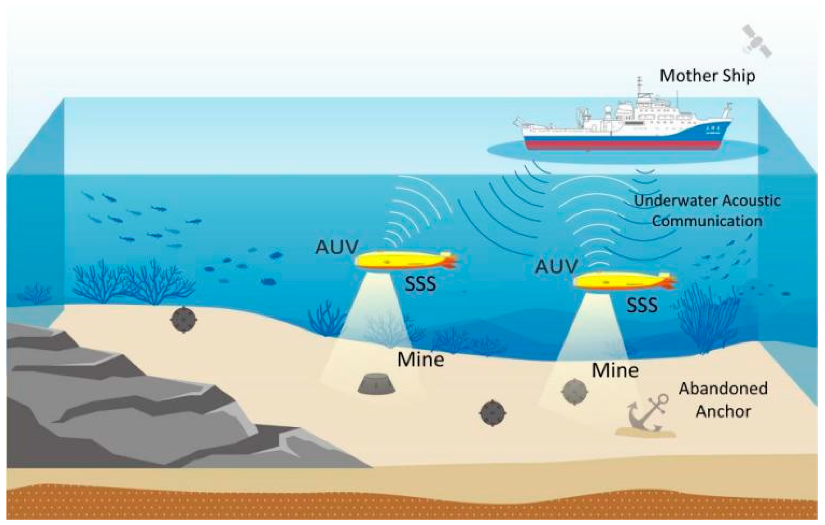
2.1. Real-Time AUV-Based SSS Underwater-Target Detection System and Process

The real-time AUV-based SSS underwater-target detection system detects underwater targets using a deep-learning-based underwater-target detection model. When performing this task, the AUV is the carrier and the SSS equipment is the main load. The AUV transmits the final detection results and the extracted underwater target feature information back to the mother ship in real time through underwater acoustic communication, thus realizing the real-time detection of underwater targets, as shown in Figure 1.
The AUV used in this study is a Black Shark I-A, as shown in Figure 2, which has a length of 2.65 m, a diameter of 0.25 m, a maximum speed of 12 kn (the cruising range is at least 100 km at the speed of 5 kn), and a maximum working depth of no less than 300 m.
The main component of the AUV task system is the SSS, which consists of two electronic components: an embedded single board computer for data processing and the SSS transducer. The SSS system detects underwater targets primarily using the principles of echo detection, and the SSS employed in the system used in this study is a Shark-S455D, which has two frequencies, 450 kHz and 900 kHz, corresponding to single-sided ranges of 150 m and 75 m, respectively. The embedded single board computer used to process the SSS data is an MIO-2263, which runs the Ubuntu operating system and is equipped with Intel Celeron J1900@2.0 GHz and Intel Atom E3825@1.33 GHz CPUs and a memory of 8 GB.
To meet the navigation accuracy requirements of the system, S3 optical fiber inertial navigation, navigator 1000 kHz DVL, and EvoLogic S2CR 18/34 underwater acoustic ultra-short baseline positioning (USBL, with underwater acoustic communication function) are selected in this system.
The AUV communication system can communicate using radio, satellite, and underwater acoustic communication. The underwater acoustic communication device used in this system is an EvoLogics S2CR, which has an ideal maximum communication distance of 3500 m, a communication frequency of 18–34 kHz, and a transmission rate of 12.5–14.5 kB/s.
Unlike the shipborne communication system, which directly uses cable transmission or satellite communication, the radio communication is used for short-distance underwater communication. The satellite communication is used to communicate with the mother ship when the AUV surfaces, and the long-distance underwater communication primarily depends on underwater acoustic communication. Because the bandwidth of underwater acoustic communication is on the order of kilobytes, the AUV cannot transmit SSS measured data long distances back to the mother ship in real time, which would be on the order of megabytes. Therefore, the AUV-based SSS underwater-target real-time detection system must perform real-time processing and intelligent detection on a sample of measured data internally and only transmit the extracted key information of the underwater target back in real time through underwater acoustic communication. On the basis of this feature, a real-time underwater-target detection process based on the AUV equipped with SSS is proposed in this paper. The overall detection process is shown in Figure 3.
The detection process consists of four steps, data acquisition, real-time processing, real-time target detection, and result output, and the steps highlighted with an orange circle indicate the key techniques involved in the method.
First, the original observation data are obtained by analyzing the data of the specified scan area of the SSS device mounted on the AUV.
Second, the obtained SSS data are processed in real time to obtain the current scan image of the SSS, and real-time noise cancelation is performed to improve the data quality as well as the accuracy of the detection model.
In the third step, the high-quality image obtained by real-time processing is input into the deep-learning-based underwater-target detection model for intelligent detection. During this step, a data augmentation technique is used to increase the number of underwater-target samples, providing a larger database for the training algorithms of the real-time detection model. This improves the generalization ability of the model and improves its performance. At the same time, the underwater-target data obtained by the detection model during the task are added to the database, which is used to enrich the database and optimize the training of the subsequent detection models, thereby further improving the detection performance and realizing a positive cycle of model training, model feedback data, and new data retraining algorithms.
Finally, the feature information of the target detected by the deep-learning-based detection model is extracted, and the key information extracted by the real-time target detection method is transmitted back to the user through underwater acoustic communication, thus completing the real-time detection of underwater targets.

2.2. Key Techniques of the Proposed Detection Method

In contrast to target detection after the event, to detect underwater targets in real time, the AUV-based SSS system needs to be able to process SSS data and detect targets in real time. To this end, this paper proposes a real-time processing method for SSS data, a method for constructing a deep-learning-based underwater-target detection model, and a real-time method for detecting underwater targets based on navigation strip images.

2.2.1. Real-Time Processing Method for SSS Data

The real-time processing of SSS data and high-quality imaging are the prerequisites for the intelligent detection of underwater targets. Because post-event processing is not possible, a real-time processing method for SSS data is proposed; the flow diagram is shown in Figure 4.
As shown in Figure 4, for the input original SSS data, a real-time decoding and data cleaning and echo intensity data conversion are performed at first to obtain the original SSS waterfall image. Secondly, to remove the water column in the middle of the original SSS waterfall image, an automatic seabed line detection is conducted. Thirdly, to transform the slant range of each echo into horizontal distance, we conduct the slant range correction based on the SSS image that has been processed by seabed line detection. Fourthly, considering the grayscale imbalance caused by the expansion and absorption losses of sound waves, a radiometric distortion correction is conducted by presenting a statistical gain method. Then, to reduce the interference of the complex environment noise, equipment noise, and other factors, a real-time noise cancellation is performed. Finally, to assign the image position information, a geocoding is conducted to transform the coordinates of the echo point in a geographic coordinate system.
(1)
Real-time Decoding and Data Cleaning
According to the data protocol, the original SSS observation data are analyzed in real time to obtain data such as echo intensity, GNSS positioning, and attitude. The SSS positioning data and attitude data are filtered by Kalman filtering to improve the quality, and the echo intensity data are interpolated and corrected to obtain high-quality original observation data.
(2)
Echo Intensity Data Conversion
The echo intensity value output by the SSS can be quantized to 11 bits or 64 bits by the system [19], and it is usually quantized again to facilitate later processing and reduce computer storage. The common quantization formula is as shown below:
n e w _ v a l u e = C × ln ( 2 n × r a w _ v a l u e 2 m )
where C is a user-defined constant, m is the number of bytes corresponding to the value range of the original echo data, and n is the number of bytes corresponding to the value range after quantization. If n = 8, the original echo intensity data are converted into a grayscale image.
(3)
Automatic Seabed Line Detection
Due to the measurement mechanism used in SSS, there is a region known as the water column in the middle of the original SSS waterfall image. This results in geometric distortion in the direction of the vertical track. The process of determining the position of the first seabed echo in each row is usually called seabed tracing, during which the seabed is detected according to the grayscale values of the water column area and the seabed image. The key to real-time detection is hence the selection of thresholds. At present, the common methods for threshold selection are the amplitude threshold method and the window slope method.
In the amplitude threshold method, an appropriate threshold is set and the first echo with an intensity greater than the threshold is identified in the echo sequence in the order of receiving time. This echo is the seabed line. The seabed line is prone to disturbance by strong echoes, so the threshold must be adjusted in real time. In the window slope method, it is assumed that the positions of the seabed line are similar in the images of several adjacent pings. A window is set, the mean value of each column of echoes within the window is counted, and the column mean curve is derived using the finite difference method. The position with the largest slope on the curve is the position of the seabed line. This approach avoids the need to update the threshold in real time. Hence, in the system described in this paper, the window slope method is used to detect the seabed line in real time.
(4)
Slant Range Correction
According to the SSS imaging mechanism, the towfish height H is calculated using the position of the first seabed echo detected by the seabed line and the recorded slant range R of each echo (the distance from the SSS to the seabed echo point) is converted to the horizontal distance L of the echo point relative to the track line as follows:
{ L = R 2 H 2 R = c t 2
where R is the propagation range of the sound wave and H represents the height of the SSS device estimated based on the position of the seabed line. After the slant range correction, distortion in the vertical track direction of the SSS waterfall image will be effectively suppressed, and the generated image reflects the true geospatial distribution of the objects detected by the SSS.
(5)
Radiometric Distortion Correction
There is radiometric distortion in the SSS image, which primarily manifests as a lateral grayscale imbalance that is caused by the expansion and absorption losses of sound waves as the propagation distance increases. Existing data acquisition software performs time varying gain (TVG) compensation using an empirical formula [21], but the compensated image is still affected by residual radiometric distortion due to the difference between sea areas. Given the complex variability in the marine environment, to completely eliminate this effect, this paper presents a statistical gain method based on the measured data. The idea of this method is to normalize the echo data to the same energy level based on mathematical statistics using the spatial distribution characteristics of the original echo intensity value. The process is as follows:
  • Take a sliding window with a width of d and a length of l, where l is twice the image scan breadth.
  • Calculate the mean value of the intensities of each column echo along the track direction within the window.
  • Calculate the mean value of the echo intensities within the window and use it as the basic value for normalization.
  • Calculate the correction coefficient for each column as follows:
a j = 1 d × l i d k l E i , k 1 d i d E i , j , E i , j = E i , j × a
where d is the width of the moving window, l is twice the image scan breadth, a is the correction coefficient, E is the intensity value of the original echo, and E′ is the intensity value after the gain.
(6)
Real-Time Noise Cancelation Correction
During the underwater operation of the AUV, the SSS image is prone to interference from marine environmental noise, equipment noise, and other factors, which is primarily manifested as salt-and-pepper noise, Gaussian noise, and stripe noise. The Gaussian noise can be eliminated by mean filtering or Gaussian filtering, the salt-and-pepper noise can be eliminated by median filtering, and the stripe noise can often be eliminated by frequency domain filtering.
(7)
Geocoding
The SSS waterfall image is formed by the echo intensity sequences arranged in measurement order, and hence it does not include coordinate information. To assign the image position information, it is necessary to transform the coordinates of the echo point in a geographic coordinate system using positioning, compass, and attitude sensor data.
As the descriptions of the above seven processing steps reveal, in contrast to post-processing, all the parameters in the real-time processing are obtained automatically using the measured data, and hence the real-time processing of SSS image data can be realized. Figure 5 shows the real-time processing of SSS data from a strip fragment. It can be seen that the original echo data are transformed into a high-quality image with geolocation information via a series of steps and real-time noise cancelation.

2.2.2. Method for Constructing the Deep-Learning-Based Detection Model

  • Implementation of the Deep-Learning-Based Detection Algorithm
Underwater-target detection requires high levels of accuracy and efficiency in the detection model. To this end, the DETR-YOLO target detection model for quick detection and the BHP-UNet target segmentation model for high-precision segmentation are proposed.
After they have been trained, the classic algorithms in the field of target detection (such as YOLO, Faster R-CNN, and the Transformer [44,45,46,47]) as well as the classic algorithms in the field of target segmentation (such as FCN, U-Net, and Deeplabv3+ [48,49,50]) can achieve the intelligent detection of underwater targets. However, these conventional algorithms cannot meet the requirements for efficiency, real-time operation, accuracy, and lightweight structure of SSS underwater targets in complex marine environments. Therefore, the design of detection and segmentation algorithms should be conducted while considering the characteristics of the marine environment, the features of the underwater-target image, and the size of the data set. Meanwhile, considering the engineering design of the AUV and the computational performance of the control module, a lightweight and compact design is adopted in terms of the algorithm structure and number of parameters.
For quick target detection, the DETR-YOLO-based SSS underwater-target detection model is proposed to improve the accuracy of small target detection, reduce the missed alarm and false alarm rates of overlapping targets in complex ocean noise background, and realize the efficiency and lightweight characteristics of the model. The specific structure of the model is shown in Figure 6.
The DETR module focuses on the effective part of the input, improves the performance of the model’s target feature learning, processes all object queries at one time during image feature processing, and outputs all prediction results simultaneously, thus greatly improving the training efficiency of the model, which helps achieve a lightweight structure in the model. The multi-scale complex feature fusion aggregates multi-layer parameters, further improving the learning of abstract features and location information. The SENet module uses a lightweight structure to increase the sensitivity of the model to channel features while increasing the computation only a small amount, further improving the performance of the model.
For high-precision target segmentation, the BHP-Unet-based SSS underwater-target segmentation model is proposed to improve the high-precision edge segmentation ability of closely arranged and overlapping underwater multi-targets and covered or semi-buried targets. The specific structure of the model is shown in Figure 7.
Using blended hybrid dilated convolution, the expansion rate of the convolution kernel is changed at multiple scales on the basis of various dilated convolutions to expand the receptive field so that the model has a better ability to recognize target areas with low responses by perceiving the surrounding high-response semantics, and the knowledge of uncommon areas containing recognition features is transferred to adjacent target areas. In this way, the feature information of the high-response part of the target object can be propagated to the adjacent target area at multiple scales. Finally, the target recognition positioning images generated at different expansion rates are fused. Thus, accurate target recognition and positioning is achieved, even for dense targets, essentially improving the recognition ability of the segmentation model.
By introducing the pyramid split attention mechanism, the multi-scale spatial information and the cross-channel attention are integrated into the feature group of each segmentation using a lightweight structure so that a better information interaction between local and global channel attentions is achieved. This enables the model to output feature images with multi-scale, global, and long-term information, increasing the overall segmentation performance of the model while only slightly increasing the amount of computation.
  • Data Augmentation Method
A sufficient number of strongly representative samples are needed to train a high-performance detection model, and this is a key component for the final development of a high-performance, deep-learning-based detection model. There is a lack of sonar image samples for underwater targets as well as actual targets with no sonar images. Therefore, in this paper, a data augmentation method is proposed that uses the SSS imaging mechanism, an underwater environment, and 3D printing. Details of the method are shown in Figure 8.
First, physical models for targets with a very small number of underwater samples or those that have not been detected but are known to exist under water, such as mines or derrick platforms, are fabricated using 3D printing. Then, using the imaging characteristics of the targets with different attributes, the SSS images of the targets under different conditions are simulated using a method based on geometry, shadow transformation, and target embedding. Finally, using the SSS imaging mechanism and sonar background features under different conditions, the SSS underwater-target image database is augmented using a style transfer method considering noise and texture.
(1)
Sample Model Fabrication Based on 3D Printing
The sample augmentation based on 3D printing can solve the problems that data are unavailable or difficult to acquire. First, the existing target is analyzed in terms of style, material, force, structure, and other factors. Then, the density of the printing material and the production characteristics of 3D printing are used to design a digital model of the target using 3D modeling software, and a process engineering drawing is produced. Next, 3D slicing software is used to specify the model printing process, including mold modification, shelling, slicing, supports, and other aspects. Finally, additive manufacturing is carried out using an industrial-grade 3D printer to obtain the physical underwater-target model.
(2)
Sample Augmentation Based on Geometry, Shadow Transformation, and Target Embedding
The SSS uses line scan imaging, and the size of the target image varies with the geometric distance (height and horizontal distance) from the device to the underwater target. Accordingly, a large number of underwater-target images can be generated. The physical target generated by 3D printing can simulate the relative relationship between the device and the target body and generate an SSS image based on the line scan imaging mechanism.
A feature of SSS imaging is that the target is accompanied by a shadow, the shadow generation is shown in Figure 9. After the target image has been generated, the shadow is generated in the form described in [51]. The specific process is as follows: Select the m × n image containing only the target, where the upper left vertex is taken as the coordinate origin, the width direction is the X-axis direction, and the length direction is the Y-axis direction. The Z-axis is perpendicular to the XY plane. The transducer moves along the track line in the direction perpendicular to the Y-axis with the coordinates as (Xacoustic, Yacoustic, Zacoustic), where Yacoustic and Zacoustic are arbitrary constants. While moving, the transducer emits sound waves toward the target to perform line scanning, traversing from left to right along the scan line. When there is a target pixel, the elevation of the pixel is calculated according to the pixel gray value Pgray, and then the shadow coordinates of the same pixel are calculated according to the principle of similar triangles. As a result, the coordinates of the pixel point are He(Xhull, Yhull, Zhull), and the coordinates of the shadow point are Se(Xshadow, Yshadow, 0). Meanwhile, the minimum and maximum values of the coordinates of shadow Y on the scan line are also calculated, and all pixels between the minimum and maximum values, except for the target pixels, are shadow area pixels. Finally, the resulting shadow burrs are smoothed by mean filtering. In the following equations, a, b, and c are arbitrary constants greater than zero.
X a c o u s t i c = X h u l l = X s h a d o w = x Y a c o u s t i c = a , Z a c o u s t i c = b , h = c x ( 0 , m ) , a ( 0 , n )
Z h u l l = P g r a y 255 h
Z h u l l Z a c o u s t i c = Y h u l l Y s h a d o w Y a c o u s t i c Y s h a d o w = λ
Y s h a d o w = Y h u l l - λ Y a c o u s t i c 1 λ
(3)
Style Transfer Sample Augmentation Considering Noise and Texture
The textures and noise levels of SSS images obtained under different SSS systems, water bodies, terrains, and substrates are quite different. These features are learned and superimposed on the previously generated target images and shadows to generate target images for different scenarios, thereby augmenting the target image sample. Image texture and noise are known as the image “style”. To implement the style transfer, a StyleBankNet network model for the underwater targets is constructed to change the style of the underwater-target image and generate a new sample. The model structure is shown in Figure 10.
First, effective information, such as the target and background of the sonar image, is deeply encoded using the encoder–decoder structure to obtain the coding features. Second, the SSS target images under different imaging conditions are input into the style transfer network, and the texture and noise under different imaging conditions are encoded in the StyleBank layer to obtain representative style templates under different conditions. Finally, the style templates are convolved with the contents generated by the encoder and then decoded by the decoder to generate SSS small target samples with different textures and noise.

2.2.3. Real-Time Method for Underwater-Target Detection with Navigation Strip Images

In actual practice, the timing and size of the SSS image input into the detection model directly determines the efficiency and accuracy of real-time detection. The SSS image is updated in real time and is usually large in size, and directly inputting it into the deep-learning-based detection model will seriously decrease efficiency, whereas compressing the image will lead to the loss of the target’s key information. Hence, a real-time method for underwater-target detection that uses navigation strip images was developed.
Considering the randomness of the underwater-target positions, to provide information that is sufficiently redundant for merging detection boxes of the same target while ensuring the detection of the target, the adjacent detection window is slid over the image with a coverage of 75%. If single-ping detection is used, the computational burden of the entire model will increase, but the increase in the number of single-ping data has no effect on the detection result of the entire target. In this paper, therefore, the sliding detection is performed on new images along with the previously measured images after the newly added 10-ping SSS data have been stitched. The real-time process of underwater-target detection is shown in Figure 11.
In the deep-learning-based process of target detection, the same target may be partially or completely detected by multiple sliding windows, or multiple targets may be detected by the same sliding window. If they are not fused or distinguished, missed alarms and false alarms may occur. Therefore, to obtain a single detection box for a single target, a confidence-based detection box weighted fusion strategy is proposed, and the specific process is shown in Figure 12, where the red boxes indicate examples.
Multiple targets of the same category or different categories may appear within the same sliding window. Therefore, before the bounding boxes are fused, it must be determined whether the bounding boxes belong to the same target. Specifically, when a sliding window detection is completed, if there is a target in the window, the detected target information should be compared with the detected target information in all adjacent windows that share the same coverage area, and the ratio of the two is calculated as follows:
T I o U = ( P i W o l ) ( P j W o l ) min ( ( P i W o l ) , ( P j W o l ) )
where P i and P j are the prediction boxes of the adjacent detection windows W i and W j , and W o l is the overlap area of the adjacent windows. When T I o U is greater than a set threshold, it will be determined that the bounding boxes belong to the same target.
To further improve the detection and positioning accuracy and avoid missed alarms when detecting overlapping or very close targets, the role of each prediction box is considered in the generation of the detection box, that is, a weight is assigned to each prediction box according to the confidence score, and the coordinates of the weighted fusion box are generated. The confidence of the fusion box is determined by the average confidence of all prediction boxes, which is calculated as follows.
x l e f t t = i = 1 n c i × x l e f t i i = 1 n c i , x r i g h t t = i = 1 n c i × x r i g h t i i = 1 n c i y t o p t = i = 1 n c i × y t o p i i = 1 n c i , y b o t t o m t = i = 1 n c i × y b o t t o m i i = 1 n c i
c t = i = 1 n c i n

3. Results

To evaluate the feasibility and effectiveness of the AUV-based SSS real-time underwater-target detection method, two real-time underwater-target detection maritime experiments were carried out in the Zhoushan Sea area in July 2022 and in the Sanya area in August 2022. The evaluation consisted of two parts, namely the construction of the deep-learning-based detection model and the maritime experiment. During the experiments, the target detected in the Zhoushan Sea area was the shipwreck marked on the chart, and the target detected in the Sanya Sea area was the 3D-printed mine model.

3.1. Detection Model Construction and Analysis

The deep-learning-based detection models implemented in the AUV system in these experiments were the DETR-YOLO and BHP-UNet detection models described in Section 3.2.1. The model pre-training was implemented in Python based on the PyTorch framework, and the hardware environment was as follows: Windows 10 operating system; CPU: Intel(R) Core(TM) i9-10900X@3.70 GHz; GPU: 2 NVIDIA GeForce RTX 3090; and parallel memory: 48 GB. The model training data categories included shipwrecks and mines. The underwater-target data augmentation was carried out using the data sample augmentation method described in Section 3.2.2, as shown in Table 1.
The augmentation results of some underwater data samples are shown in Figure 13.
It can be seen from the figure that the newly added SSS underwater-target images obtained using the data sample amplification method show the target features very well, which solves the problem of the lack of underwater-target sample data to a certain extent. In this experiment, the training sets and the test sets in the data sets were divided using a ratio of 4:1, and ten-fold cross-validation was used to train the model. During training, the initial learning rate was set to 0.0001, the learning rate was adjusted in real time using the Adam algorithm, the number of epochs was set to 1200, and the batch size was set to 32 according to the computer’s configuration.
In this experiment, the average precision (AP) was used as the metric to evaluate the accuracy of the detection model, where AP_0.5 refers to the AP value when the intersection over union (IOU) was set to 0.5 and AP_0.5:0.95 indicates the average of the AP values when the IOU threshold ranged from 0.5 to 0.95 in intervals of 0.05, calculated as follows:
A P = 0 1 P ( R ) d R
P = T P T P + F P ,   R = T P T P + F N ,
The dice score and IOU were used as metrics to evaluate the segmentation performance of the model. They are, respectively, calculated as follows:
D i c e = 2 × Precision × Recall Precision + Recall = 2 T P 2 T P + F P + F N = 2 | X Y | | X | + | Y |
I o U = T P T P + F P + F N
At pixel-level detection, precision, which measures the accuracy of the result, refers to the probability that the positive samples are actually detected as positive samples. Recall, which measures the completeness of the result, refers to the probability that the positive samples are detected as positive samples. Moreover, TP (true positives) indicates the positive samples detected correctly, and FP (false positives) indicates the positive samples detected incorrectly. TN (true negatives) denotes the negative samples detected correctly, and FN (false negatives) denotes the negative samples detected incorrectly. Finally, | X | refers to the ground truth, indicating the real pixels of the target, and | Y | refers to the predicted mask, which indicates the segmented pixels predicted by the model. FPS (frames per second) and weights are used as metrics to evaluate the efficiency and structural complexity of the detection model. The detection and segmentation performances of proposed models on the test set are given in Table 2 and Table 3.
According to Table 2, the proposed DETR-YOLO realized 84.5% AP0.5 and 57.7% AP0.5–0.95 with 431 FPS on the test data of the shipwreck target, which is better than the mine target. This is because the shipwreck target is bigger and more distinct than the mine target, and it has more abundant features such as the texture and outline.
As for the segmentation task, the performances of the proposed BHP-UNet for the mine target and the shipwreck target are similar. Although the shipwreck target is more distinct, it has more complex detailed features than the mine target. Hence, when faced with the segmentation task, the BHP-UNet achieved a better efficiency for the mine target with 132 FPS.

3.2. Maritime Experiments and Analysis

3.2.1. Shipwreck Target Experiment

The sea area targeted in this experiment is located in an area south of Nanyuanshan Mountain in the Zhoushan Islands. According to the chart data, this sea area has an average water depth of about 40 m. Near the coordinates (30°11′49.776″ N, 122°19′31.696″ E), there are shipwreck targets. The offshore deployment of the AUV is shown in Figure 14.
The track line of the AUV is shown in Figure 15. During the experiment, the AUV scanned the seabed to detect underwater targets at a fixed height of 20 m, an average speed of 3.5 kn, and a scan breadth of 150 m.
In the actual operation of the AUV, a total of four survey lines were deployed, including three planned lines and one inspection line. Of these, for three survey lines, the UAV transmitted back the key information of underwater targets at the approximate positions indicated by red dots in Figure 15, the red dot in the figure is the area of this experiment.
In this paper, the real-time information transmitted from the No. 40-3 survey line is shown as an example. The key information of the underwater target was transmitted at a point about two nautical miles from the mother ship, and it included the information such as images, the category of the target, the coordinates of the center point, and the geometric dimension of the underwater target, as shown in Figure 16. The transmission speed was 13.8 kB/s, and the total data volume was 246 kB.
As Figure 16 shows, the real-time transmitted SSS image waterfall image has clear noise cancelation effects, even under the conditions of complex seawater noise found in the Zhoushan Sea area, and the deep-learning-based detection model proposed in this paper detected the underwater shipwreck target well. Moreover, the coordinates of the detected shipwreck were similar to the position marked in the chart, and the shipwreck height was calculated to be 6.44 m using the geometric feature-extraction method. The correctness of this value cannot be verified, but it is consistent with the value given by traditional experience.

3.2.2. Mine Target Experiment

The area targeted in this experiment is located in the southeast of Hainan Niuqizhou Island. According to the chart data, it has an average water depth of about 30 m. The mine model produced by 3D printing was 2 m in diameter, as shown in Figure 17, and it was deployed at the location shown in Figure 18.
The track line of the AUV is shown in Figure 18. During the experiment, the AUV scanned the seabed to detect underwater targets with a fixed height of 15 m, an average speed of 3 kn, and a scan breadth of 150 m.
In the actual operation of the AUV, a total of five survey lines were deployed, four planned routes and one inspection line. Because of the small size of the mine target, the UAV transmitted back key information of the underwater target for only two of the survey lines. The approximate locations are indicated by the red dots in Figure 18, the red dot is the point where the AUV found the target. In this paper, the No. 30-2 survey line is shown. The key information of the underwater target was transmitted back at a point one nautical mile from the mother ship and included the information such as images, the target category, the coordinates of the center point, and the geometric dimensions of the underwater target, as shown in Figure 19. The transmission speed was 14.3 kB/s, and the total data volume was 194 kB.
Figure 19 reveals that the transmitted coordinates for the mine were slightly different from the coordinates where the mine was deployed, which may have been caused by the movement of the mine target due to the impact of the seabed inrush and positioning error of the AUV. In addition, the geometric information transmitted back indicates that the horizontal edge of the mine was 1.75 m and its longitudinal edge was 2.01 m, which is almost the same as the actual diameter of 2 m. Although the size of the mine is relatively small, the deep-learning-based detection model proposed in this paper still intelligently detected the mine target and realized the real-time transmission of key information.
The above two experiments demonstrate that the system proposed in this paper realized real-time AUV-based SSS underwater-target detection, proving that the method is feasible and the key techniques are effective, which will have great guiding significance in practice.

4. Discussion

4.1. Significance of the Proposed Method

It is proved that the AUV-based side-scan sonar real-time method for underwater-target detection proposed in this paper is maneuverable and effective through the above experiments, which solves the challenge brought by the limitation of underwater acoustic communication to a certain extent. The following key technologies proposed in this paper are further discussed.

4.1.1. Data Augmentation Method

A sufficient number of strongly representative samples is a key component for the detection model. Under the premise of few or even zero samples, the proposed method realizes the data samples from “none” to “have” through 3D printing and realizes the data samples from “have” to “many” by combining the imaging features of different attributes, the imaging mechanism of SSS, and the sonar background features under different conditions. Compared with the SSS sample augmentation method that takes into account five aspects of target diversity, target texture, imaging resolution, equipment and environmental noise, and background [52], our method obtains more realistic and detailed augmented samples.
As can be seen from Figure 20, the image augmented by our method in this paper has higher resolution, complete detail features, and a stronger sense of reality.
In order to verify the influence of the augmented samples on the performance of the proposed underwater-target detection model, three sets of data were designed to train the DETR-YOLO and BHP-Unet models, taking the shipwreck target as the experimental object, and the number of images remained the same at 500. A total of 100 real SSS shipwreck images were selected to evaluate the performance of the trained model. Evaluation indicators are consistent with those in Section 4.1.
As can be seen from Table 4 and Table 5, the detection performance of the DETR-YOLO model and BHP-Unet model trained by Group 2 is higher than that of the other two groups, indicating that our method is superior to the method [52] and even better than the real SSS image, which proves the effectiveness of our method and can be a crucial help in improving model performance.

4.1.2. Deep-Learning-Based Detection Algorithm

Underwater-target detection requires high levels of accuracy and efficiency in the detection model. The proposed DETR-YOLO target detection model realized the goal for quick detection, and the proposed BHP-UNet target segmentation model realized the goal for high-precision segmentation.
To study the influence of the DETR module on YOLO and the BHP module on UNet, we conducted the ablation study and compared the AP0.5, AP0.5–0.95, FPS, and size of weights filed in different settings. The results are shown in Table 6 and Table 7.
For the influence of the DETR module on YOLOv5, according to Table 4, the DETR-YOLO achieved a better performance than the raw YOLOv5a in detection precision and efficiency no matter when faced with the mine target or shipwreck target. Specifically speaking, the DETR module improved the YOLOv5a by increasing the AP0.5 and AP0.5–0.95 by 2.3% and 9.5% for the mine target and 2.7% and 6.1% for the shipwreck target. Therefore, the self-attention mechanism of the DETR module can focus more on the target area, especially for the small target.
For the influence of the BHP module for UNet, according to Table 5, the BHP-UNet achieved 77.33% mean dice and 78.12% mean IOU with 127 mean FPS. Therefore, the BHP module improved the dice and IOU of U-Net by 8.38% and 7.91% for the mine target and 9.05% and 6.24% for the shipwreck target with little extra efficiency burden. Therefore, the BHP module is helpful to segment both the large and small targets by the multi-scale features.
In order to further verify the performance of the proposed model, comparison experiments were conducted with conventional models (Transformer, Faster R-CNN, YOLOv5), and data set composition, experimental configuration, and training strategy were consistent with those in Section 4.1.
As Table 8 and Table 9 reveal, the DETR-YOLO model has an AP score that is significantly higher than those of the other three models, indicating a better detection performance, whereas the BHP-UNet model is superior to the other two models in terms of both dice score and IOU, indicating the best segmentation performance. In addition, both models proposed in this paper have a more complex structure, but there is only a very small gap in complexity relative to the Transformer and U-Net, which have the simplest structure and the fastest speed in terms of FPS and weights, which indicates that the lightweight structure and high efficiency of the detection model proposed in this paper fully meets the requirements for real-time detection.

4.1.3. Comparison with other AUV-Based Detection Methods

To further evaluate the performance of this proposed method, the proposed method is also compared with the existing AUV-based underwater-target detection methods. The comparison results are listed in Table 10.
According to Table 10, method 2 initially proposed an AUV-based acoustic image object recognition system, but it still requires manual feature extraction. Method 3 is the preliminary attempt to automate underwater detection, but the scarcity of data results in that the classification algorithm is overly sensitive to the mislabeled data. Our method achieved a better performance in terms of segmentation quality and speed compared with method 4. Comparatively, our method achieved the best performance, and overcomes the limitation of underwater acoustic communication, thus under-water target real-time detection is realized.

4.2. Limitations of the Proposed Method

4.2.1. Real-Time Processing Method for SSS Data

Affected by the seabed reverberation and environmental noise, the SSS image noise is extremely complex. Considering that AUV real-time processing needs to be fast and timely while avoiding taking up too much computational resources, this paper only uses simple mean, median, and frequency domain filtering for processing, which can eliminate most of the pepper and Gaussian noise, and the remaining small amount of noise is blended with the target. Although it will cause some interference in the final imaging, according to the study of Huang et al. [52], the residual noise has less impact on the deep-learning-based underwater-target recognition task, which means that the needs of AUV underwater recognition can be satisfied by using a simple method. However, if the time requirement is not high and the computational resources are sufficient, better results can be achieved by using complex denoising methods such as non-downsampling Contourlet transform [53].

4.2.2. Data Augmentation Method

In the actual operation process, the proposed method costs a lot because it involves the production of a solid model and the actual maritime experiments to obtain the real SSS images, but, compared with the traditional sample augmentation only through optical image and hand-painted image, it at least has the characteristics of real SSS. In addition, although 3D printing can make objects with known material, texture, and structure, it cannot restore objects with unknown properties well. Meanwhile, this paper has not analyzed the internal structure of objects. However, in general, the proposed method can be fully applied to the augmentation of deep-learning training data under the condition of few or even zero samples, and a high-performance detection model can be obtained.

4.2.3. Real-Time Method for Underwater-Target Detection

In the sea experiment in Section 3.2, the overall sea condition is good, but the real-time information return effect is greatly affected under complex sea conditions (especially large swell); at the same time, due to the limitation of hardware performance of underwater acoustic communication equipment, it is easy to cause garbled code in the process of real-time information transmission under complex sea conditions. In addition, the confusion of AUV velocity and the transmitting frequency of SSS caused by the drastic change of AUV attitude will also lead to a poor effect of the real-time method for detection with navigation strip images. However, in general, when the sea conditions are not particularly bad, it can meet the target of underwater-target real-time detection.

5. Conclusions

To address the problem that the SSS data of an AUV cannot be transmitted back and processed in real time due to the limitation of underwater acoustic communication, which means that targets cannot be detected in real time, this paper proposed a real-time AUV-based SSS method for detecting underwater targets and analyzed the key techniques involved. The main innovations of this paper include the following three aspects:
  • A real-time AUV-based SSS underwater-target detection method was proposed that includes the system composition and implementation process.
  • A real-time processing method for SSS data, a method for constructing a deep-learning-based underwater-target detection model, and a real-time underwater-target detection method based on navigation strip images were proposed. These methods solve the three key technical problems of real-time data processing, deep-learning-based detection model construction, and real-time target detection using SSS based on an AUV.
  • Through two actual maritime experiments, the real-time intelligent detection of underwater targets using an SSS device on an AUV platform was realized, proving the feasibility of the proposed method and the effectiveness of the key techniques, providing a new solution for AUV-based SSS underwater-target real-time detection.
In summary, the proposed method for the AUV-based SSS real-time underwater-target detection and the key techniques proposed in this paper have overcome the limitations of underwater acoustic communication to a certain extent and realized real-time, efficient, and intelligent underwater-target detection, which will have high significance for guiding practice and engineering implementation and can serve to meet the needs of military applications in specific scenarios in the future. Further research priorities include research exploring key techniques further; optimizing the engineering implementation, for example, the compatibility between hardware and software; and further investigating multi-source detection techniques, such as detection using a combination of SSS and forward-looking sonar as well as a combination of magnetic, optical, and electrical systems to further improve the accuracy of detection.

Author Contributions

Conceptualization, Y.T.; methodology, Y.T.; software, Y.T.; validation, S.J., C.H., and J.Z.; formal analysis, C.H. and Y.Y.; investigation, Y.T.; resources, L.W. and J.Z.; data curation, Y.T.; writing—original draft preparation, Y.T.; writing—review and editing, C.H. and Y.Y.; visualization, Y.T.; supervision, C.H. and J.Z.; project administration, J.Z. and L.W.; funding acquisition, J.Z. and L.W. All authors have read and agreed to the published version of the manuscript.

Funding

This research was funded by the National Natural Science Foundation of China, grant number 41876103 and 42176186, and the National Key Research and Development Program, grant number 2022YFC2808303.

Institutional Review Board Statement

Not applicable.

Informed Consent Statement

Not applicable.

Data Availability Statement

Access to the data will be considered upon request by the authors.

Acknowledgments

We would like to thank Kimberly Moravec for editing the English text of a draft of this manuscript. We would like to thank the editor and the anonymous reviewers for their valuable comments and suggestions that greatly improve the quality of this paper.

Conflicts of Interest

The authors declare no conflict of interest.

References

  1. Cao, H. Development status of deep-sea exploration technology and equipment in China. Ship Supplies Mark. 2005, 2, 19–22. [Google Scholar]
  2. Wang, J.; Cao, J.; Lu, B.; He, B. Underwater Target Detection Project Equipment Application and Development Trend. China Water Transp. 2016, 11, 43–44. [Google Scholar]
  3. Henriksen, L. Real-time underwater object detection based on an electrically scanned high-resolution sonar. In Proceedings of the 1994 Symposium on Autonomous Underwater Vehicle Technology, Cambridge, MA, USA, 19–20 July 1994; pp. 99–104. [Google Scholar]
  4. Arshad, M.R. Recent advancement in sensor technology for underwater applications. Indian Mar. Sci. 2009, 38, 267–273. [Google Scholar]
  5. Greene, A.; Rahman, A.F.; Kline, R.; Rahman, M.S. Side scan sonar: A cost-efficient alternative method for measuring seagrass cover in shallow environments. Estuar. Coast. Shelf Sci. 2018, 207, 250–258. [Google Scholar] [CrossRef]
  6. Natalia, H.; Narcis, P.; Arnau, C.; Marc, C. Autonomous detection, following and mapping of an underwater chain using sonar. Ocean Eng. 2017, 130, 336–350. [Google Scholar]
  7. Flowers, H.J.; Hightower, J.E. A Novel Approach to Surveying Sturgeon Using Side-Scan Sonar and Occupancy Modeling. Mar. Coast. Fish. 2013, 5, 211–223. [Google Scholar] [CrossRef]
  8. Johnson, S.G.; Deaett, M.A. The application of automated recognition techniques to side-scan sonar imagery. IEEE J. Ocean. Eng. 1994, 19, 138–144. [Google Scholar] [CrossRef]
  9. Avilash, S.; Santosha, K.; Dwivedya, P. Advancements in the field of autonomous underwater vehicle. Ocean Eng. 2019, 181, 145–160. [Google Scholar]
  10. Yu, S.-C. Development of real-time acoustic image recognition system using by autonomous marine vehicle. Ocean Eng. 2008, 35, 90–105. [Google Scholar] [CrossRef]
  11. Wu, Y.; Zhao, Y.; Lang, S. Development of Autonomous Underwater Vehicles Technology. Strateg. Study CAE 2020, 22, 26–31. [Google Scholar] [CrossRef]
  12. Burguera, A.; Bonin-Font, F. On-Line Multi-Class Segmentation of Side-Scan Sonar Imagery Using an Autonomous Underwater Vehicle. J. Mar. Sci. Eng. 2020, 8, 557. [Google Scholar] [CrossRef]
  13. Rutledge, J.; Yuan, W.; Wu, J. Intelligent Shipwreck Search Using Autonomous Underwater Vehicles. In Proceedings of the IEEE International Conference on Robotics and Automation (ICRA), Brisbane, QLD, Australia, 21–25 May 2018; p. 15623. [Google Scholar]
  14. Chen, E.; Guo, J. Real time map generation using sidescan sonar scanlines for unmanned underwater vehicles. Ocean Eng. 2014, 91, 252–262. [Google Scholar] [CrossRef]
  15. Kondo, H.; Ura, T. Navigation of an AUV for investigation of underwater structures. Control Eng. Pract. 2004, 12, 1551–1559. [Google Scholar] [CrossRef]
  16. Feezor, M.D.; Sorrell, F.Y.; Blankinship, P.R.; Bellingham, J.G. Autonomous underwater vehicle homing/docking via electromagnetic guidance. IEEE J. Ocean. Eng. 2001, 26, 515–521. [Google Scholar] [CrossRef]
  17. Zheng, T.; Chao, S.; Zong-wei, L.; Di, M. Multi-sensor data fusion for underwater target recognition under uncertainty. In Proceedings of the IEEE 2010 2nd International Conference on Information Science and Engineering: ICISE 2010, Hangzhou, China, 4–6 December 2010; pp. 1315–1318. [Google Scholar]
  18. Blondel, P. The Handbook of Sidescan Sonar; Springer Science & Business Media: Berlin/Heidelberg, Germany, 2010. [Google Scholar]
  19. Wang, A.X. Research on 3D Seafloor Terrian Recovery from the Side Scan Sonar Image. Ph.D. Thesis, Wuhan University, Wuhan, China, 2014; pp. 45–48. [Google Scholar]
  20. Chavez, P.S., Jr.; Isbrecht, J.; Galanis, P. Processing, mosaicking and management of the Monterey Bay digital sidescan-sonar images. Mar. Geol. 2002, 181, 305–315. [Google Scholar] [CrossRef]
  21. Chang, Y.C.; Hsu, S.K.; Tsai, C.H. Side-scan sonar image processing: Correcting Brightness Variation and Patching Gaps. Mar. Sci. Technol.-Taiw. 2010, 18, 785–789. [Google Scholar]
  22. Wilken, D.; Feldens, P.; Wunderlich, T.; Heinrich, C. Application of 2D Fourier filtering for elimination of stripe noise in side-scan sonar mosaics. Geo-Mar. Lett. 2012, 32, 337–347. [Google Scholar] [CrossRef]
  23. Burguera, A.; Oliver, G. High-resolution underwater mapping using side-scan sonar. PLoS ONE 2016, 11, 0146396. [Google Scholar] [CrossRef] [Green Version]
  24. Yan, J.; Meng, J.; Zhao, J. Real-time bottom tracking using side scan sonar data through one-dimensional convolutional neural networks. Remote Sens. 2019, 12, 37. [Google Scholar] [CrossRef] [Green Version]
  25. Cho, H.; Yu, S.-C. Real-time sonar image enhancement for AUV-based acoustic vision. Ocean Eng. 2015, 104, 568–579. [Google Scholar] [CrossRef]
  26. Vasamsetti, S.; Mittal, N.; Neelapu, B.C.; Sardana, H.K. Wavelet based perspective on variational enhancement technique for underwater imagery. Ocean Eng. 2017, 141, 88–100. [Google Scholar] [CrossRef]
  27. Corchs, S.; Schettini, R. Underwater image processing: State of the art of restoration and image enhancement methods. EURASIP Adv. J. Signal Process. 2010, 2018, 746052. [Google Scholar]
  28. Nayak, N.; Nara, M.; Gambin, T.; Wood, Z.; Clark, C.M. Machine learning techniques for AUV side-scan sonar data feature extraction as applied to intelligent search for underwater archaeological sites. Field Serv. Robot. 2021, 16, 219–233. [Google Scholar]
  29. Yang, F.; Du, Z.; Wu, Z. Object Recognizing on Sonar Image Based on Histogram and Geometric Feature. Mar. Sci. Bull. 2006, 25, 64–69. [Google Scholar]
  30. Langner, F.; Knauer, C.; Jans, W.; Ebert, A. Side Scan Sonar Image Resolution and Automatic Object Detection, Classification and Identification. In Proceedings of the OCEANS 2009—Europe Conference, Bremen, Germany, 11–14 May 2009. [Google Scholar]
  31. Xiao, W.; Zhao, J.; Zhu, B.; Jiang, T.; Qin, T. A Side Scan Sonar Image Target Detection Algorithm Based on a Neutrosophic Set and Diffusion Maps. Remote Sens. 2018, 10, 295. [Google Scholar]
  32. Fakiris, E.; Papatheodorou, G.; Geraga, M.; Ferentinos, G. An Automatic Target Detection Algorithm for Swath Sonar Backscatter Imagery, Using Image Texture and Independent Component Analysis. Remote Sens. 2016, 8, 373. [Google Scholar] [CrossRef] [Green Version]
  33. Dura, E.; Zhang, Y.; Liao, X.J.; Dobeck, G.J.; Carin, L. Active learning for detection of mine-like objects in side-scan sonar imagery. IEEE J. Ocean. Eng. 2005, 30, 360–371. [Google Scholar] [CrossRef] [Green Version]
  34. Song, Y.; He, B.; Liu, P. Real-Time Object Detection for AUVs Using Self-Cascaded Convolutional Neural Networks. IEEE J. Ocean. Eng. 2021, 46, 56–67. [Google Scholar] [CrossRef]
  35. Topple, J.M.; Fawcett, J.A. MiNet: Efficient Deep Learning Automatic Target Recognition for Small Autonomous Vehicles. IEEE Geosci. Remote Sens. Lett. 2020, 16, 186–197. [Google Scholar] [CrossRef]
  36. Huo, G.Y.; Yang, S.X.; Li, Q.W.; Zhou, Y. A Robust and Fast Method for Sidescan Sonar Image Segmentation Using Nonlocal Despeckling and Active Contour Model. IEEE Trans. Cybern. 2017, 47, 855–872. [Google Scholar] [CrossRef]
  37. Feldens, P.; Darr, A.; Feldens, A.; Tauber, F. Detection of Boulders in Side Scan Sonar Mosaics by a Neural Network. Geosciences 2019, 4, 159. [Google Scholar] [CrossRef] [Green Version]
  38. Zheng, L.; Tian, K. Detection of small objects in sidescan sonar images based on POHMT and Tsallis entropy. Signal Process. 2018, 6, 142168–142177. [Google Scholar] [CrossRef]
  39. Li, C.L.; Ye, X.F.; Cao, D.X.; Hou, J.; Yang, H.B. Zero shot objects classification method of side scan sonar image based on synthesis of pseudo samples. Appl. Acoust. 2021, 173, 107691. [Google Scholar] [CrossRef]
  40. Bore, N.; Folkesson, J. Modeling and Simulation of Sidescan Using Conditional Generative Adversarial Network. IEEE J. Ocean. Eng. 2021, 46, 195–205. [Google Scholar] [CrossRef]
  41. Coiras, E.; Mignotte, P.Y.; Petillot, Y.; Bell, J.; Lebart, K. Supervised target detection and classification by training on augmented reality data. IET Radar Sonar Navig. 2007, 1, 83–90. [Google Scholar] [CrossRef] [Green Version]
  42. Zheng, G.; Zhang, H.; Li, Y.; Zhao, J. A Universal Automatic Bottom Tracking Method of Side Scan Sonar Data Based on Semantic Segmentation. Remote Sens. 2021, 13, 1945. [Google Scholar] [CrossRef]
  43. Xu, Y.; Wang, X.; Wang, K.; Shi, J.; Sun, W. Underwater sonar image classification using generative adversarial network and convolutional neural network. IET Image Process. 2020, 14, 2819–2825. [Google Scholar] [CrossRef]
  44. Kapetanović, N.; Mišković, N.; Tahirović, A. Saliency and Anomaly: Transition of Concepts from Natural Images to Side-Scan Sonar Images. In Proceedings of the 21st IFAC World Congress 2020, Berlin, Germany, 12–17 July 2020. [Google Scholar]
  45. Steiniger, Y.; Kraus, D.; Meisen, T. Survey on deep learning based computer vision for sonar imagery. Eng. Appl. Artif. Intell. 2022, 114, 105157. [Google Scholar] [CrossRef]
  46. Tang, Y.; Jin, S.; Bian, G.; Zhang, Y. Shipwreck Target Recognition in Side-scan Sonar Images by Improved YOLOv3 Model Based on Transfer Learning. IEEE Access 2019, 8, 173450–173460. [Google Scholar]
  47. Tang, Y.; Jin, S.; Bian, G.; Zhang, Y.; Li, F. The Transfer Learning with Convolutional Neural Network Method of Side-scan Sonar to Identify Wreck Images. Acta Geod. Cartogr. Sin. 2021, 50, 260–269. [Google Scholar]
  48. Tang, Y.; Li, H.; Zhang, W.; Bian, S.; Zhai, G.; Liu, M.; Zhang, X. Lightweight DETR-YOLO method for detecting shipwreck target in side-scan sonar. Syst. Eng. Electron. 2022, 44, 2427–2436. [Google Scholar]
  49. Chen, L.C.; Papandreou, G.; Kokkinos, I.; Murphy, K.; Yuille, A.L. Deeplab: Semantic image segmentation with deep convolutional nets, atrous convolution, and fully connected crfs. IEEE Trans. Pattern Anal. Mach. Intell. 2018, 40, 834–848. [Google Scholar] [CrossRef] [PubMed] [Green Version]
  50. Long, J.; Shelhamer, E.; Darrell, T. Fully convolutional networks for semantic segmentation. In Proceedings of the IEEE Conference on Computer Vision and Pattern Recognition, Boston, MA, USA, 7–12 June 2015; pp. 3431–3440. [Google Scholar]
  51. Wang, H.; Gao, N.; Xiao, Y.; Tang, Y. Image feature extraction based on improved FCN for UUV side-scan sonar. Mar. Geophys. Res. 2020, 41, 18. [Google Scholar] [CrossRef]
  52. Huang, C.; Zhao, J.; Yu, Y.; Zhang, H. Comprehensive Sample Augmentation by Fully Considering SSS Imaging Mechanism and Environment for Shipwreck Detection Under Zero Real Samples. IEEE Trans. Geosci. Remote Sens. 2021, 60, 1–14. [Google Scholar] [CrossRef]
  53. Chen, G.Y.; Bui, T.D. Image denoising with neighbour dependency and customized wavelet and threshold. Pattern Recognit. 2005, 38, 115–124. [Google Scholar] [CrossRef]
Figure 1. Diagram of the real-time AUV-based SSS underwater-target detection system.
Jmse 11 00690 g001
Figure 2. Black Shark I-A AUV. (a) Overall diagram of the AUV. (b) Real AUV at the terminal.
Jmse 11 00690 g002
Figure 3. Real-time underwater-target detection process based on an AUV equipped with SSS.
Jmse 11 00690 g003
Figure 4. SSS data processing.
Jmse 11 00690 g004
Figure 5. Output images of the main steps of SSS data processing.
Jmse 11 00690 g005
Figure 6. Structure of the DETR-YOLO model.
Jmse 11 00690 g006
Figure 7. Structure of the BHP-UNet model.
Jmse 11 00690 g007
Figure 8. Data augmentation method based on 3D printing.
Jmse 11 00690 g008
Figure 9. Shadow generation.
Jmse 11 00690 g009
Figure 10. StyleBankNet network model.
Jmse 11 00690 g010
Figure 11. Real-time target detection strategy.
Jmse 11 00690 g011
Figure 12. Confidence-based weighted fusion strategy flowchart.
Jmse 11 00690 g012
Figure 13. Examples of augmented underwater-target samples. (a) Mine target samples. (b) Shipwreck target samples.
Jmse 11 00690 g013
Figure 14. AUV offshore deployment.
Jmse 11 00690 g014
Figure 15. Task track in the Zhoushan Sea area.
Jmse 11 00690 g015
Figure 16. Key information transmission for the shipwreck target.
Jmse 11 00690 g016
Figure 17. Mine model produced by 3D printing.
Jmse 11 00690 g017
Figure 18. Track line in the Sanya Sea area.
Jmse 11 00690 g018
Figure 19. Key information transmission for the mine target.
Jmse 11 00690 g019
Figure 20. Augmented SSS images. (a) SSS images augmented by the proposed method. (b) SSS images augmented adapted from Huang et al. [52] with permission from IEEE CCC, 2023.
Jmse 11 00690 g020
Table 1. Details of the underwater-target data sets.
CategoryNumber of Original Training Data ImagesNumber of Sample Augmented Data ImagesRatio of Training to Test Data
Shipwreck61212004:1
Mine81004:1
Table 2. Detection performances of the DETR-YOLO model.
Mine TargetShipwreck Target
ModelAP0.5/%AP0.5–0.95/%FPSWeights/MBAP0.5/%AP0.5–0.95/%FPSWeights/MB
DETR-YOLO76.556.942718.284.557.743120.1
Table 3. Segmentation performances of the BHP-UNet model.
Mine TargetShipwreck Target
ModelDice/%IOU/%FPSWeights/MBDice/%IOU/%FPSWeights/MB
BHP-UNet76.3378.5213264.278.3177.7112166.2
Table 4. Composition of training set.
GroupReal SSS ImageGenerated by Proposed MethodGenerated by [52] Method
1 150000
2 205000
3 300500
1 The data in Group 1 are made up of real SSS images. 2 The data in Group 2 are made up of SSS images augmented by our method. 3 The data in Group 3 are made up of SSS images augmented by [52] method.
Table 5. Performances of the models trained with different sets.
ModelAP0.5/%AP0.5–0.95/%Dice/%IOU/%
DETR-YOLO-179.950.5--
DETR-YOLO-283.154.9--
DETR-YOLO-380.750.2--
BHP-Unet-1--72.672.2
BHP-Unet-2--73.175.6
BHP-Unet-3--71.569.7
Table 6. Influence of the DETR module on YOLOv5.
Mine TargetShipwreck Target
ModelAP0.5/%AP0.5–0.95/%FPSWeights/MBAP0.5/%AP0.5–0.95/%FPSWeights/MB
YOLOv5a74.247.442616.181.851.643018.6
DETR-YOLO76.556.942718.284.557.743120.1
Table 7. Influence of the BHP module on UNet.
Mine TargetShipwreck Target
ModelDice/%IOU/%FPSWeights/MBDice/%IOU/%FPSWeights/MB
U-Net67.9570.6113562.169.2671.4712665.9
BHP-UNet76.3378.5213264.278.3177.7112166.2
Table 8. Comparison of the detection performances of the DETR-YOLO model and conventional models.
Mine TargetShipwreck Target
ModelAP0.5/%AP0.5–0.95/%FPSWeights/MBAP0.5/%AP0.5–0.95/%FPSWeights/MB
Transformer68.541.943913.677.343.944218.3
YOLOv574.247.442616.181.851.643018.6
Faster R-CNN74.344.240830.780.3149.941134.6
DETR-YOLO76.556.942718.284.557.743120.1
Table 9. Comparison of segmentation performances of the BHP-UNet model and conventional models.
Mine TargetShipwreck Target
ModelDice/%IOU/%FPSWeights/MBDice/%IOU/%FPSWeights/MB
U-Net67.9570.6113562.169.2671.4712665.9
DeepLabv3+73.0172.5895100.176.8075.2088103.6
BHP-UNet76.3378.5213264.278.3177.7112166.2
Table 10. Comparison of our method with the existing AUV-based real-time underwater-object detection methods.
NumMethodAlgorithmTaskObjectAccuracyEfficiency
1OursDETR-YOLO
BHP-UNet
Detection and
Segmentation
Mine Target
Shipwreck
80.5% AP
78.1% IOU
429 FPS (detection)
127 FPS (segmentation)
2Son-Cheol Yu
(2008) [10]
BinarizationDetectionCubic
Cylindrical
--
3Jeffrey Rutledge
(2018) [13]
ResnetDetectionTarget93.75% recall and 20.71% precision (data set A)
18.18%% recall and 10.43% precision (data set B)
-
4Burguera et al.
(2020) [12]
Fully Convolutional
Neural Network
SegmentationRock
Sand
Other
87.8% (F1 score, AUV)4.6 milliseconds per
100 pixels (AUV)
Disclaimer/Publisher’s Note: The statements, opinions and data contained in all publications are solely those of the individual author(s) and contributor(s) and not of MDPI and/or the editor(s). MDPI and/or the editor(s) disclaim responsibility for any injury to people or property resulting from any ideas, methods, instructions or products referred to in the content.

