
A Curved Plate-Flattening Method to Construct the Membrane Strain Distribution
Abstract
:1. Introduction
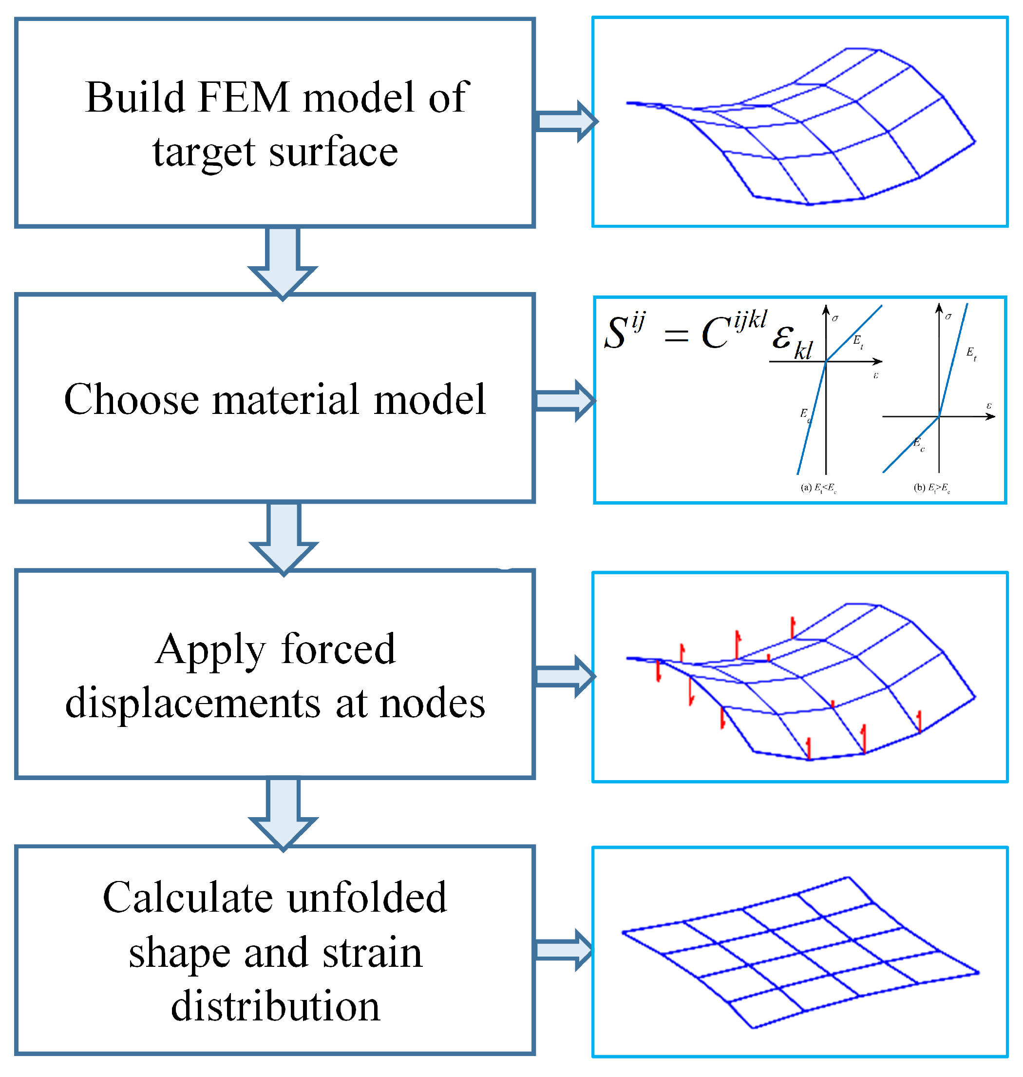
2. Basic Theory and Strategy
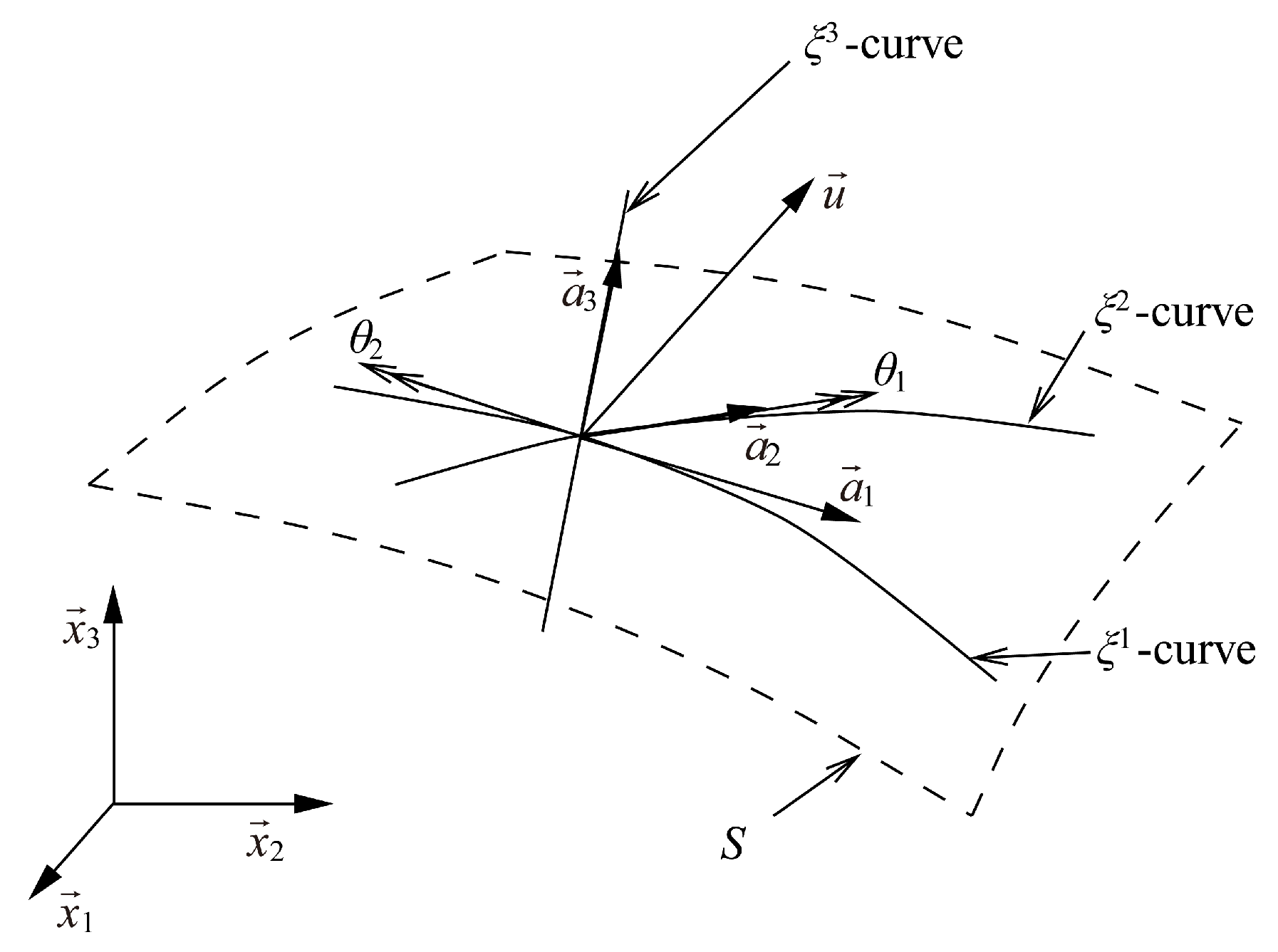
2.1. Shell Mathematical Models
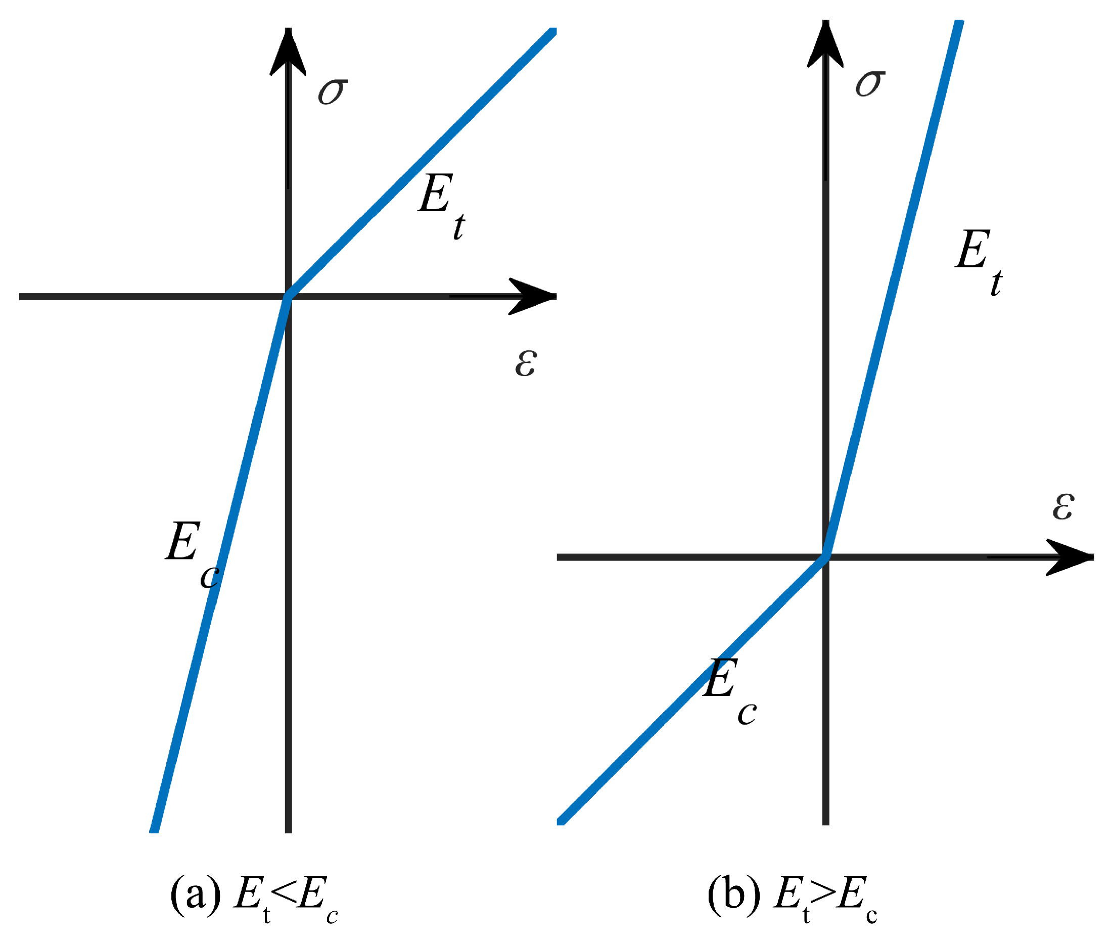
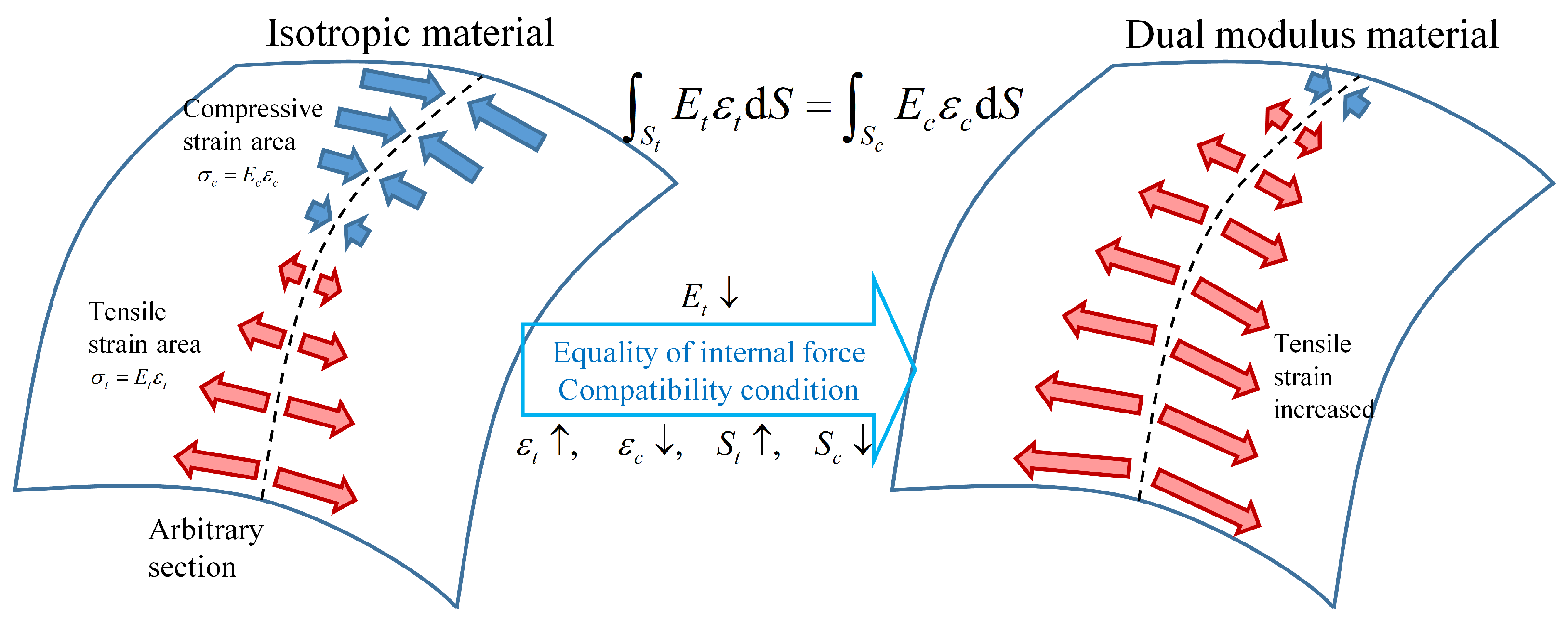
2.2. Constrain the Magnitude of Membrane Strain
2.3. Constrain the Direction of Membrane Strain
3. Numerical Example
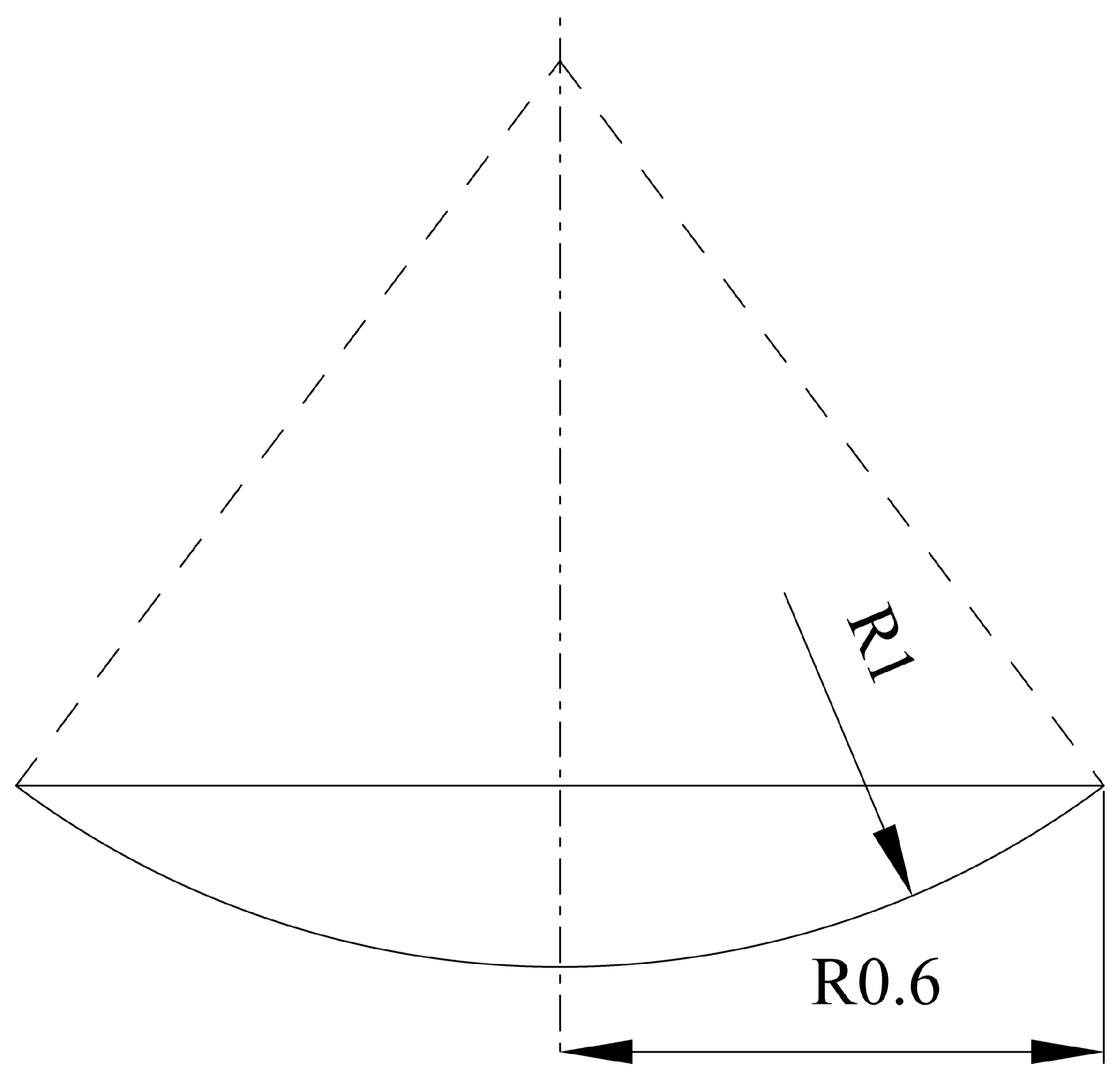
3.1. Spherical Cap
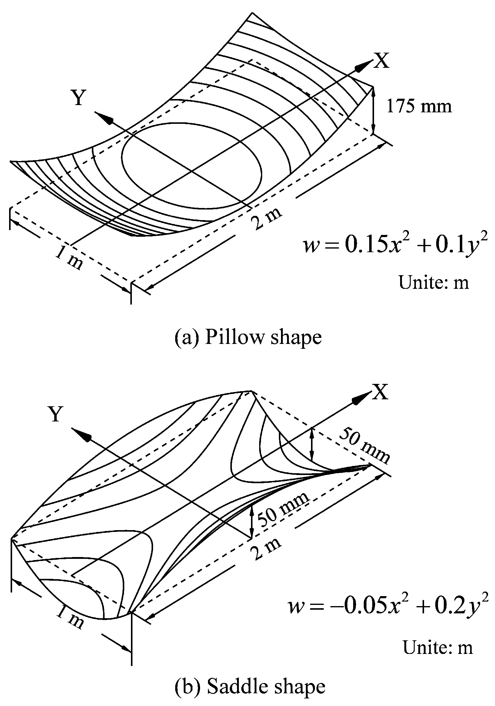
3.2. Pillow and Saddle Shape
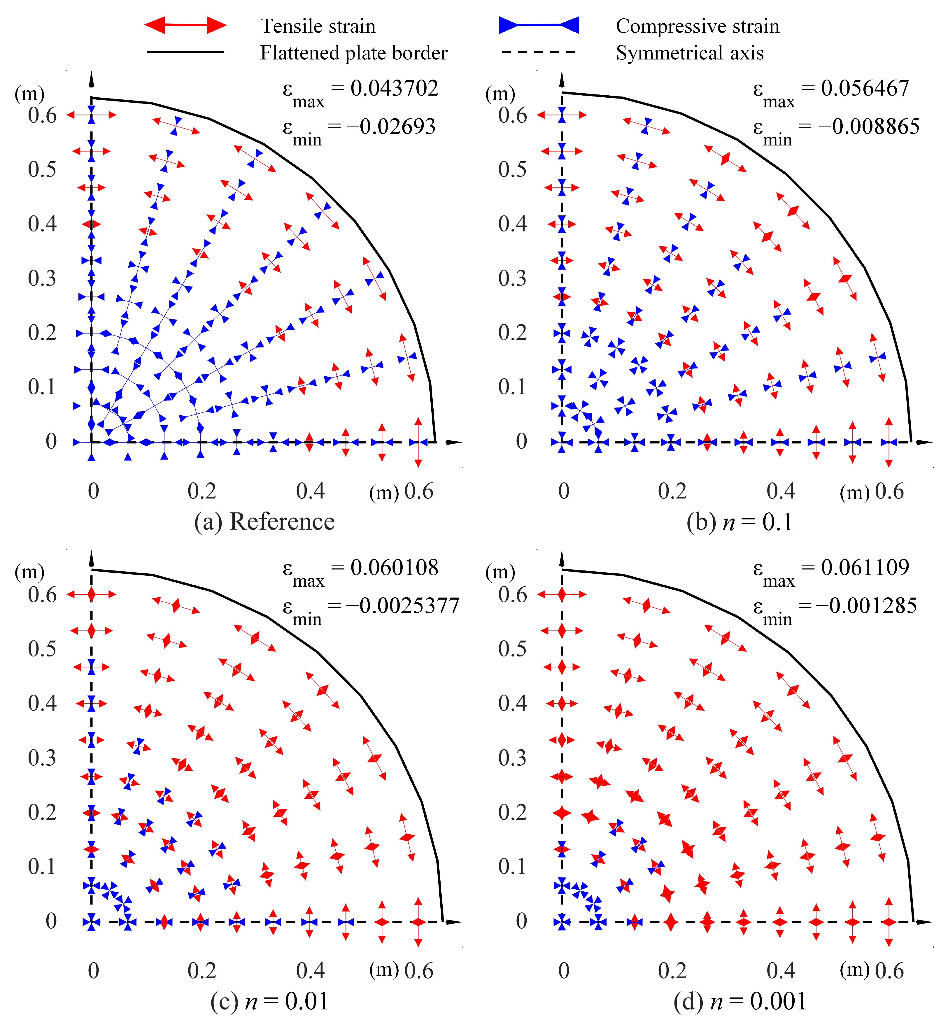
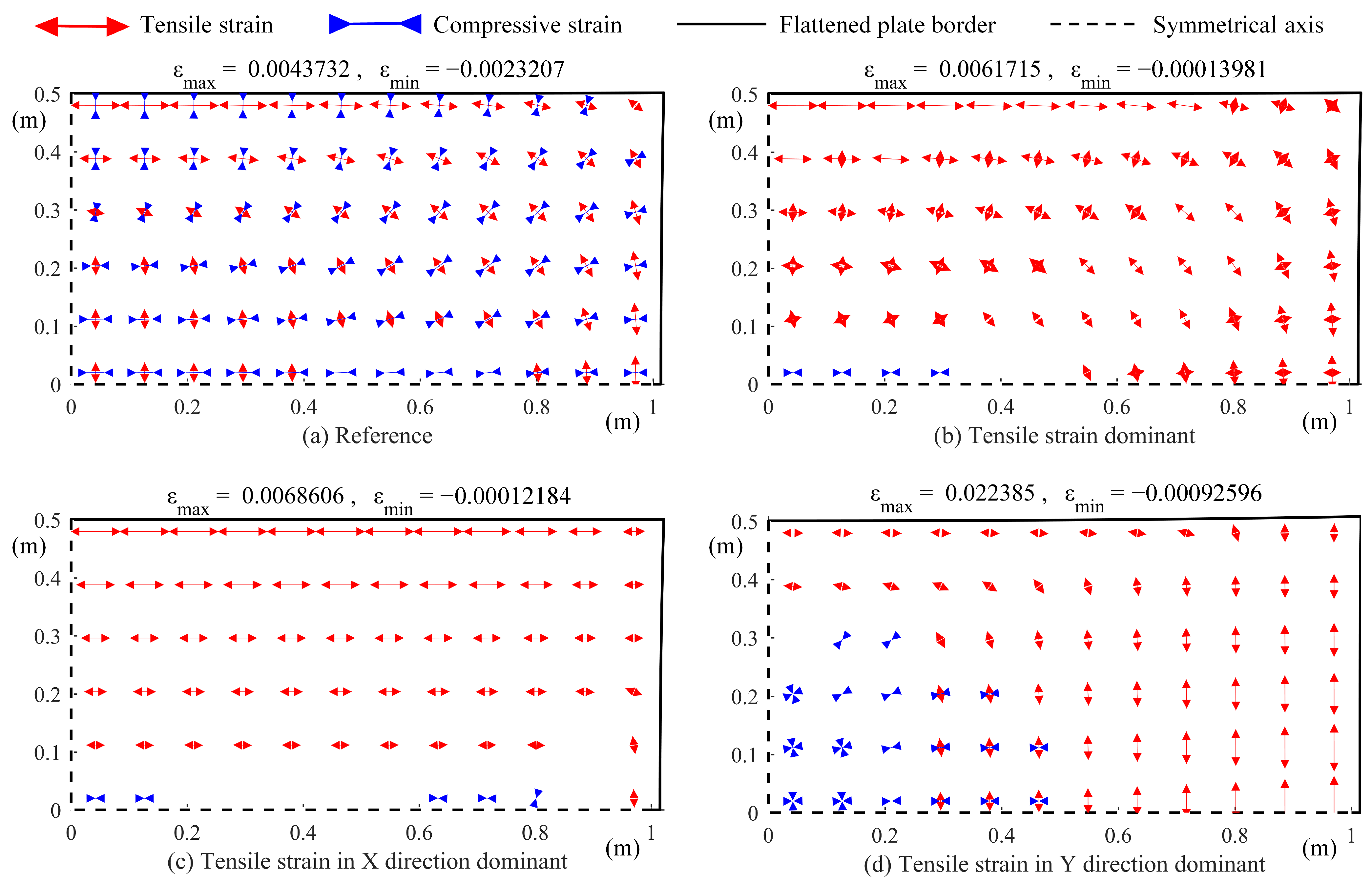
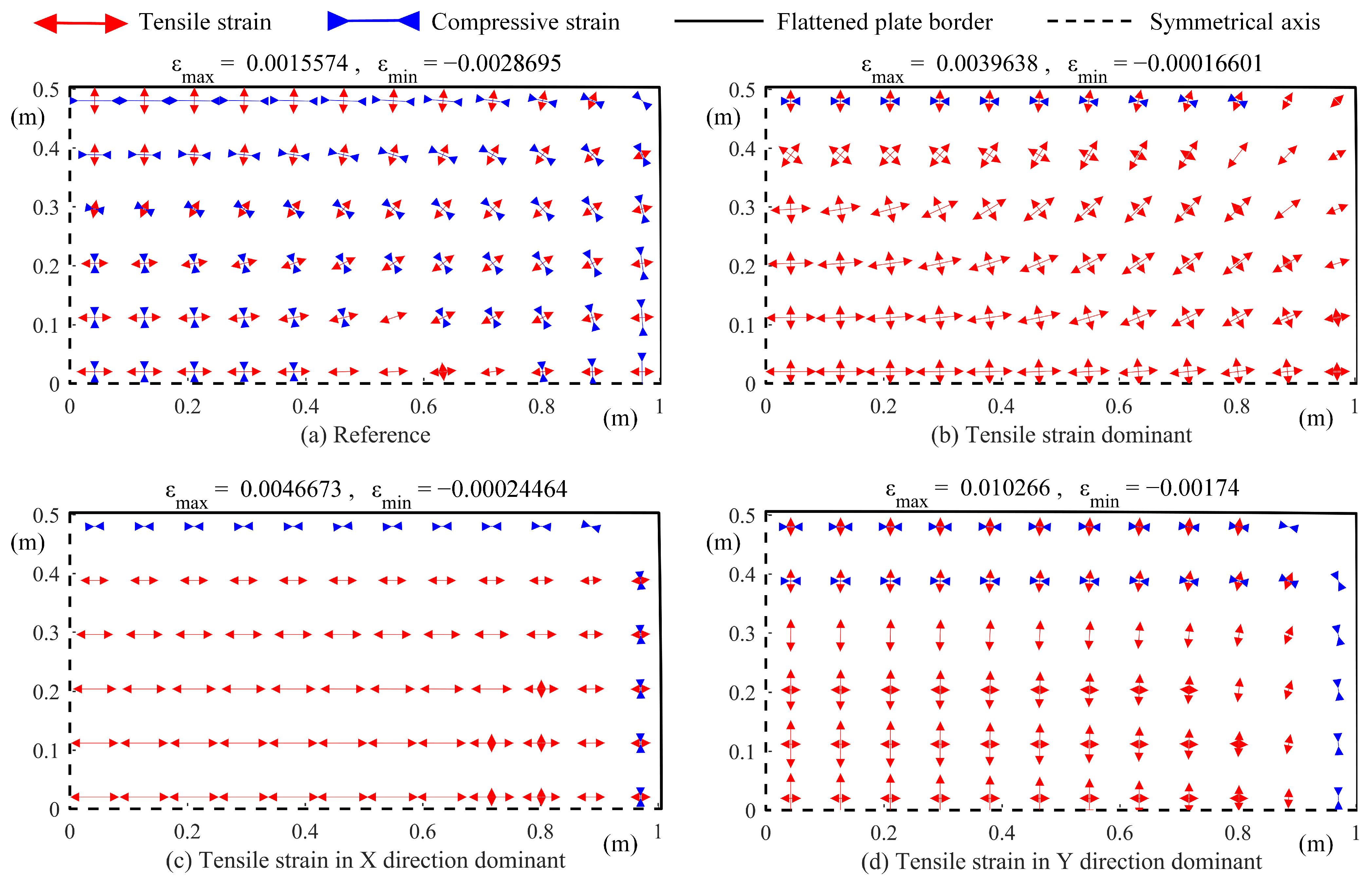
- Using the general steel constitutive relations to produce tensile strain without constraint as a reference result,
- Using a constructed constitutive relation to produce tensile strain dominant, setting factor ,
- Using a constructed constitutive relation to produce tensile strain in X direction dominant, setting factors and ,
- Using a constructed constitutive relation to produce tensile strain in Y direction dominant, setting factors and .
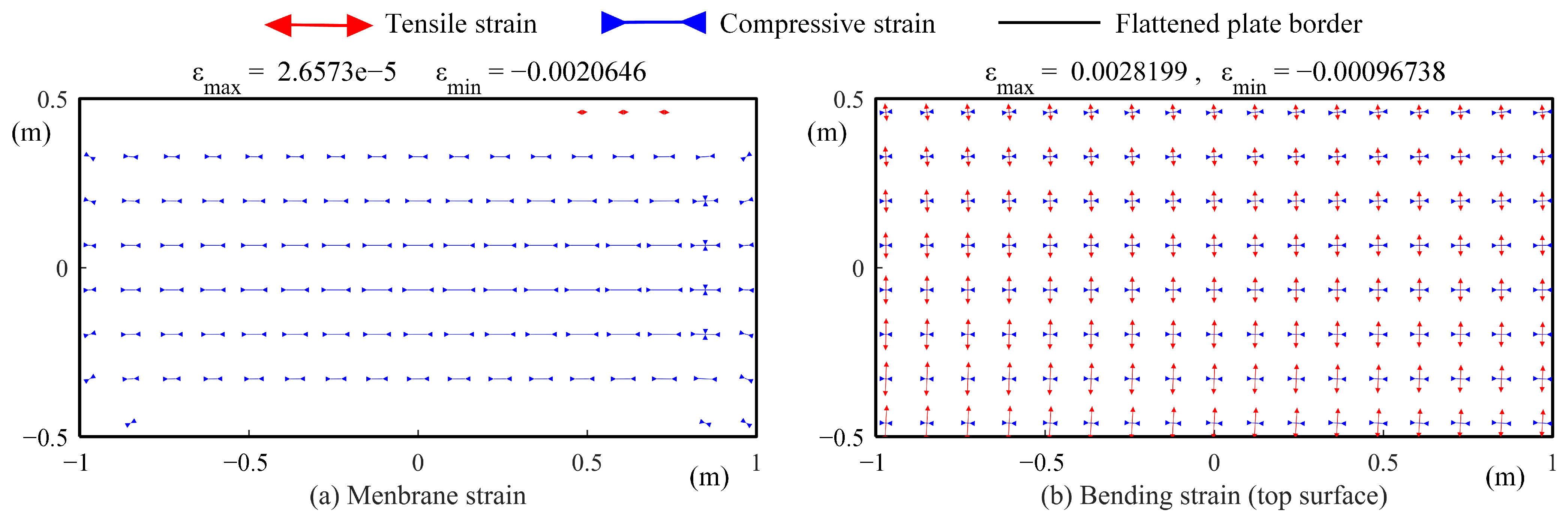
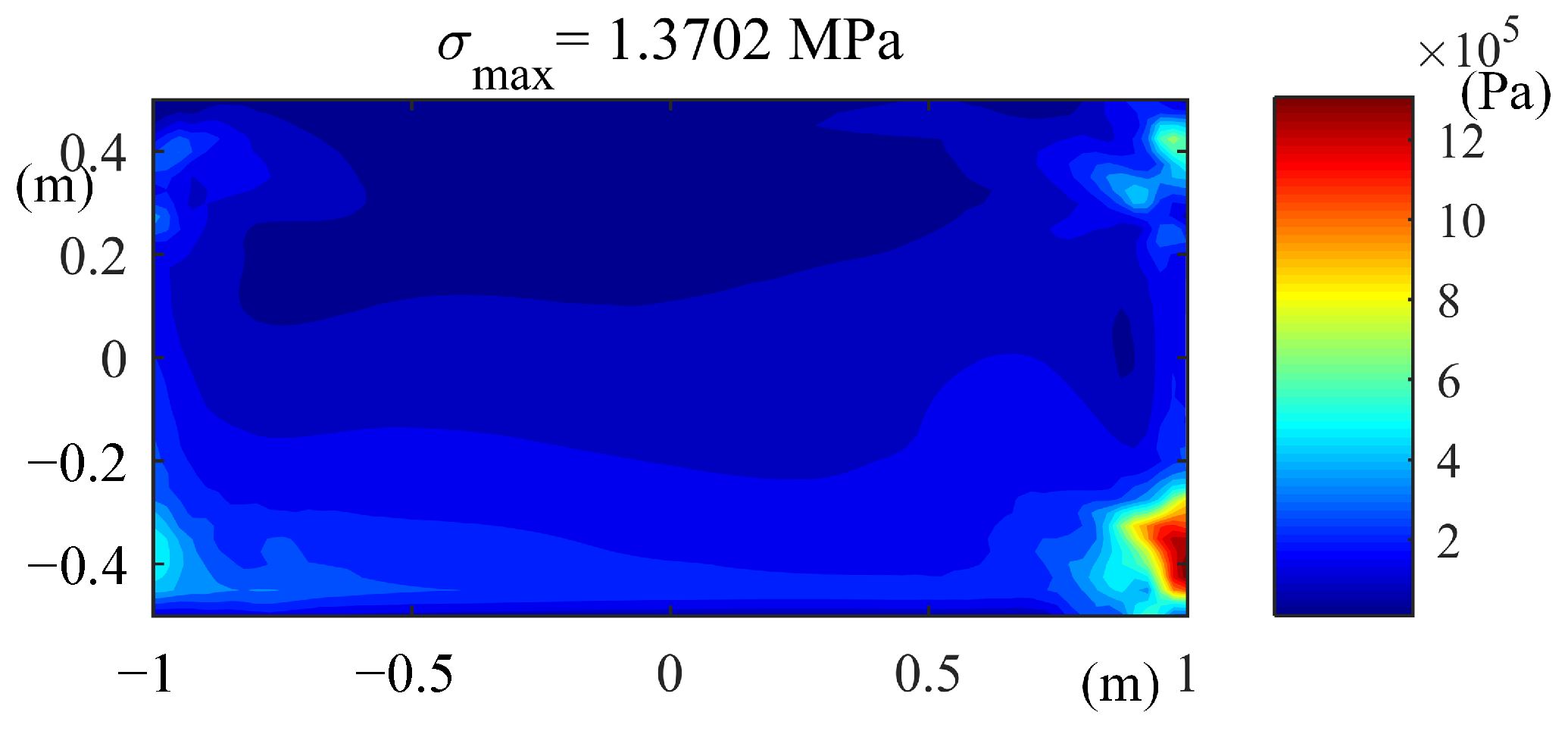
3.3. Comparison and Verification
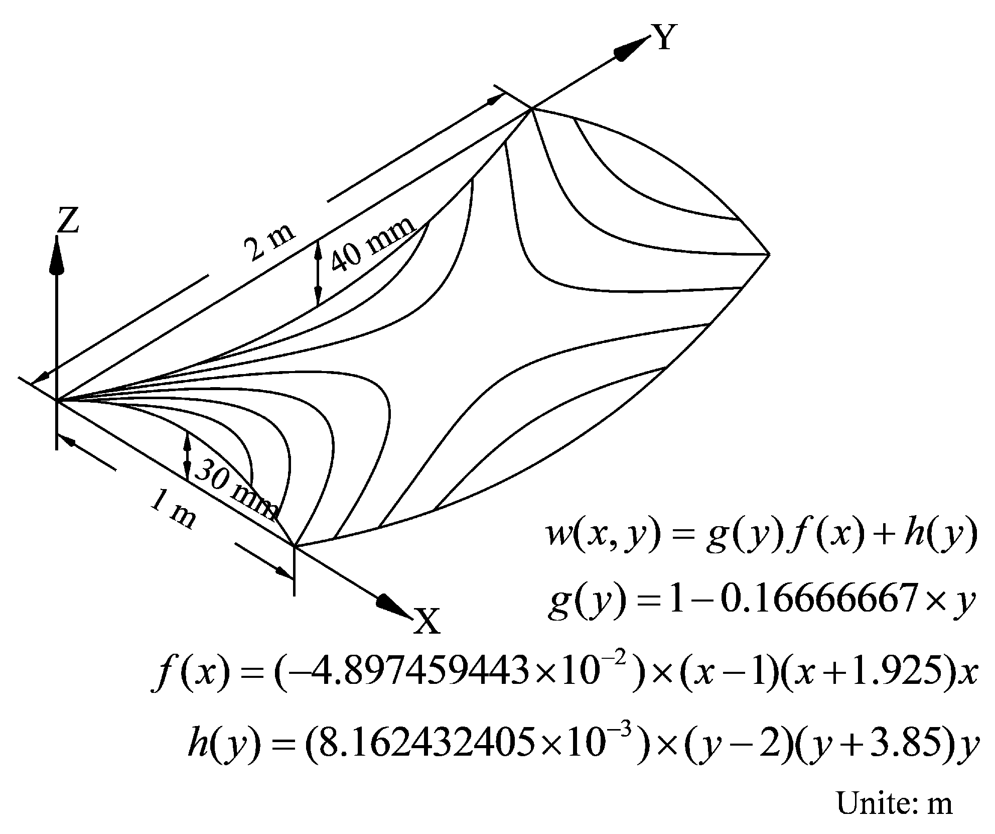
4. Application
- Flatten the target surface according to the above method with constraint, and obtain the inherent strain distribution required.
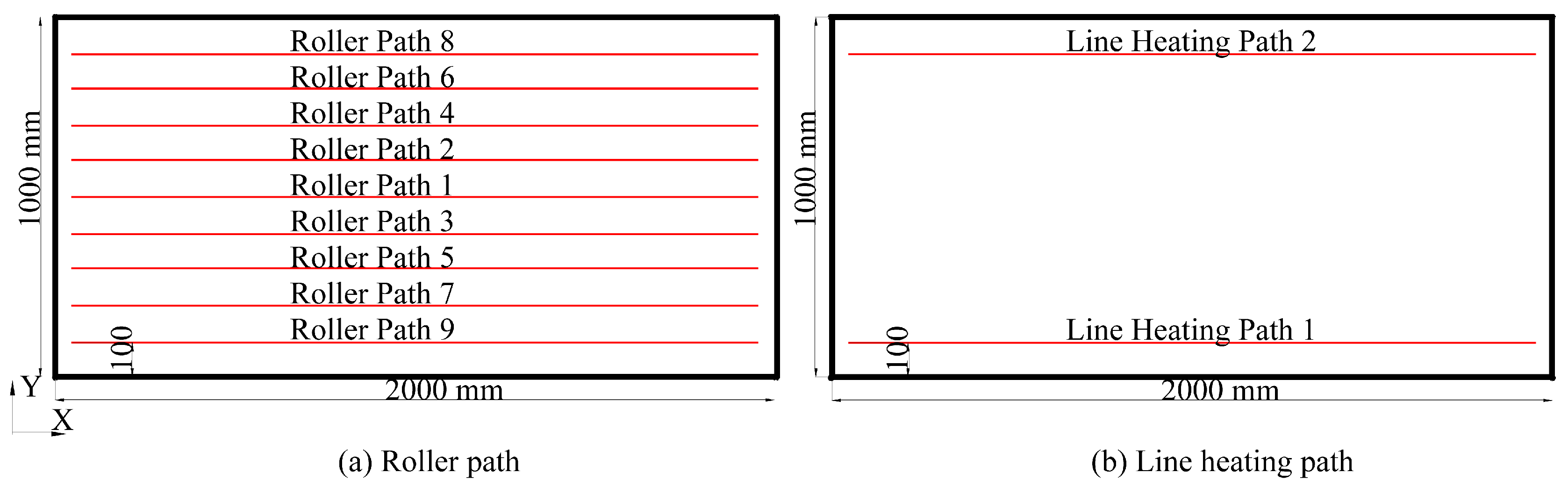
- Design the forming plan according to the inherent strain distribution. Lay out the rolling line in the direction perpendicular to the bending strain and the heating line in the area of high membrane strain. Select processing parameters according to the processing parameter database.
- Carry out the forming process simulation to verify the forming plan.
- Carry out the forming experiment, and compare it with the target shape.
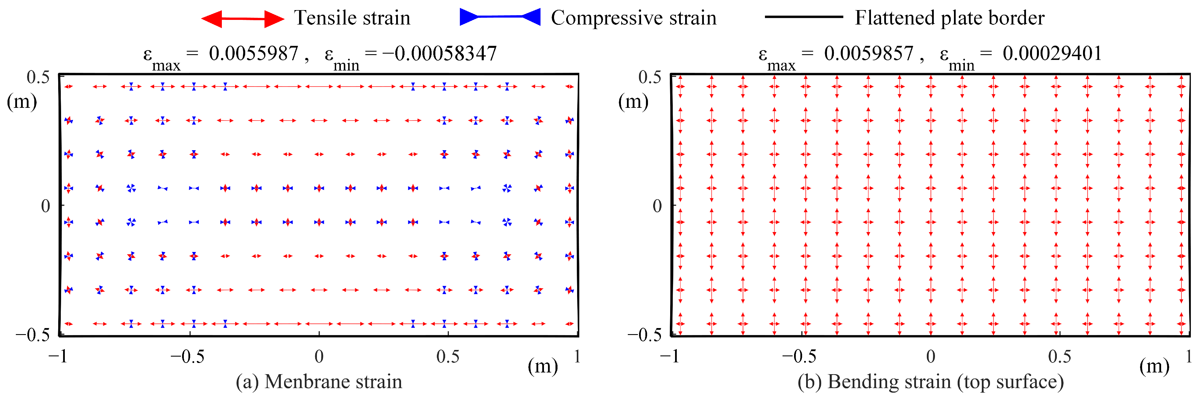
4.1. Surface Flattening and Process Plan
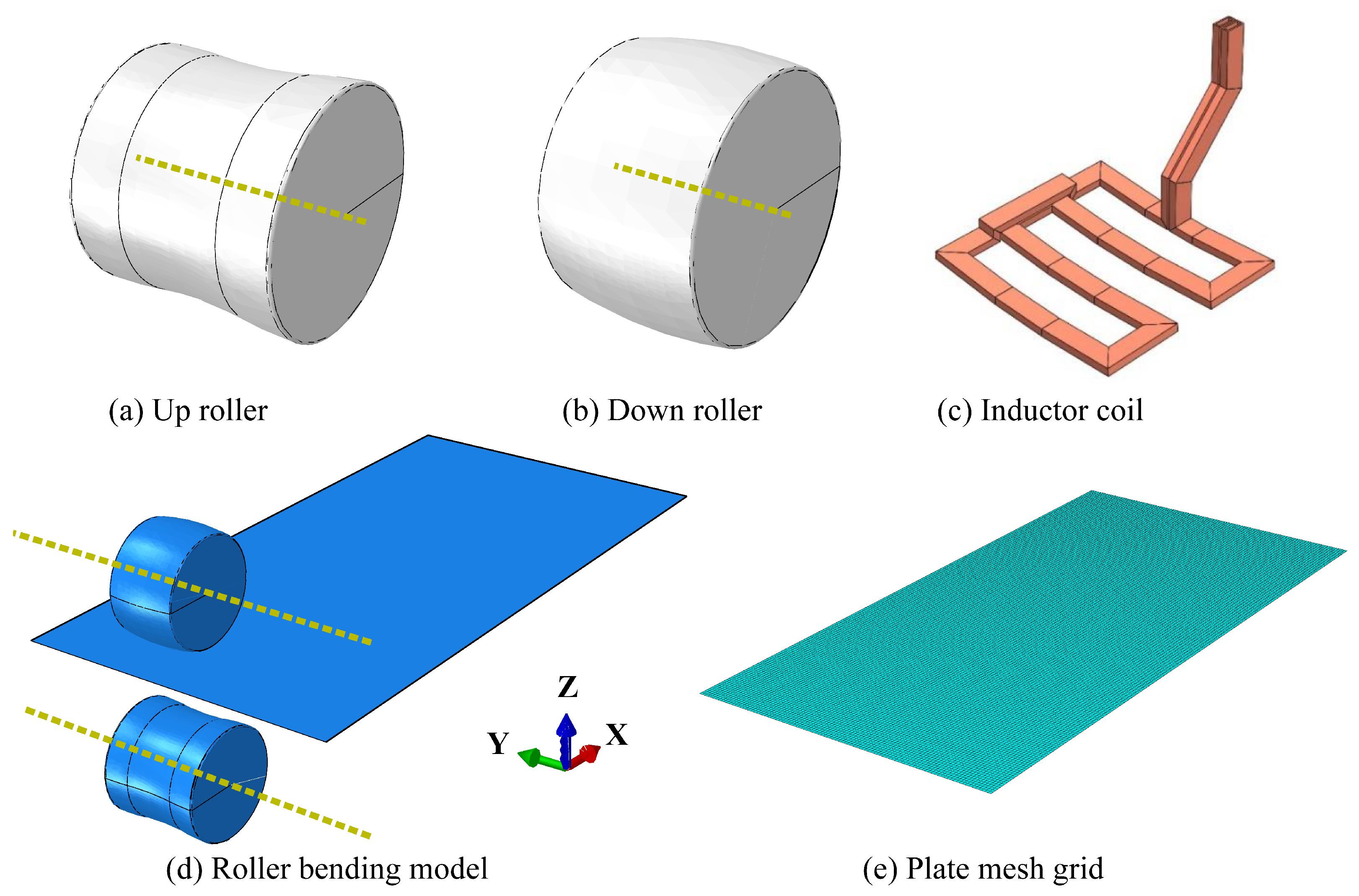
4.2. Finite Element Simulation
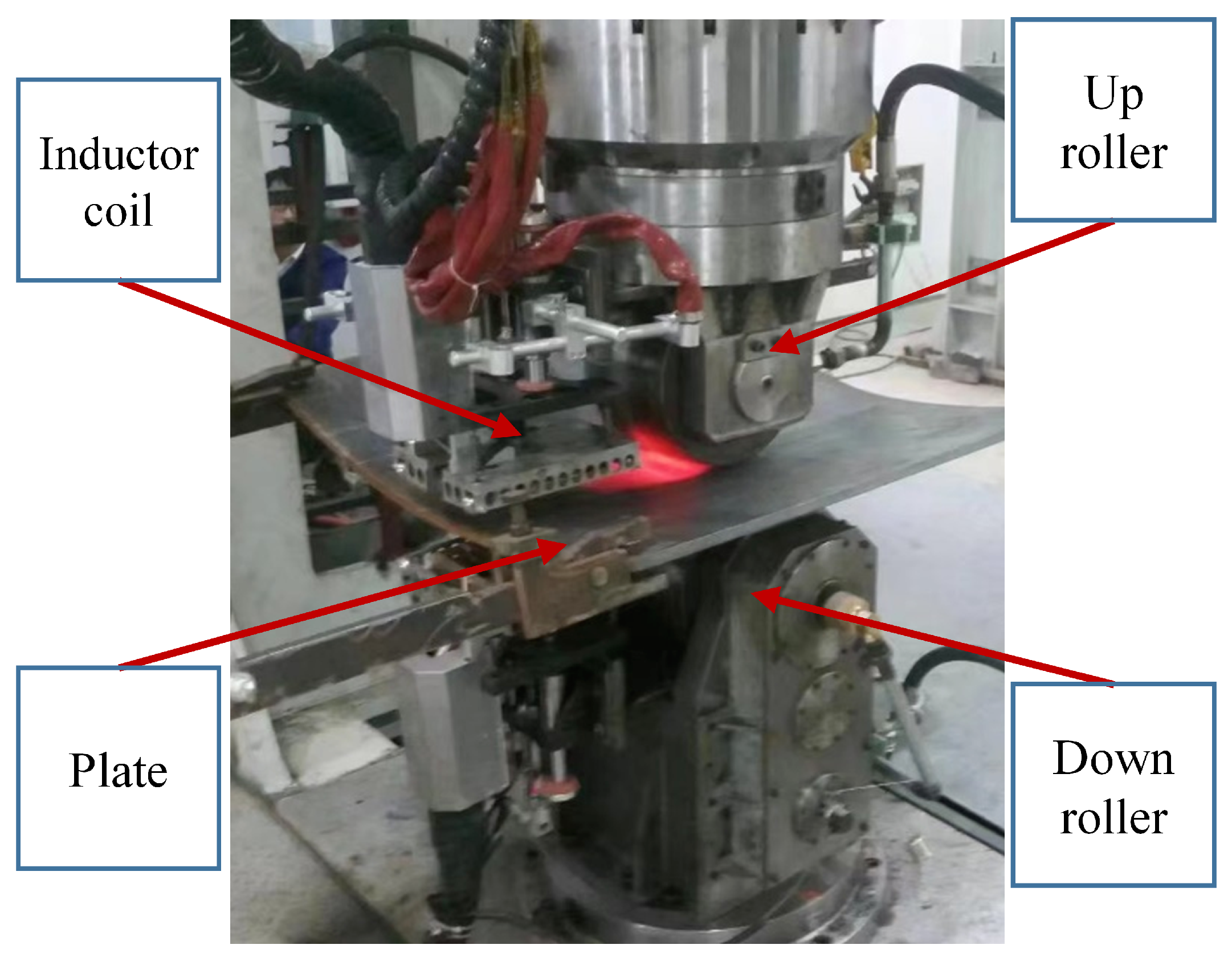
4.3. Experiment
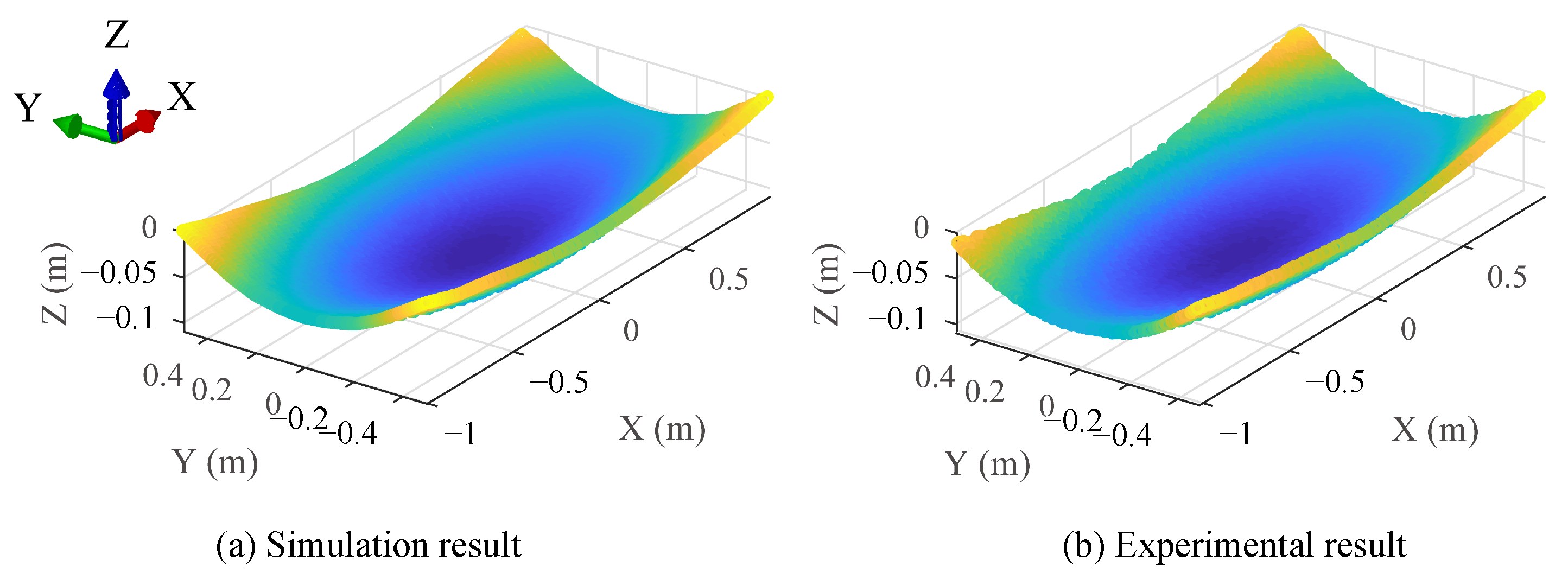
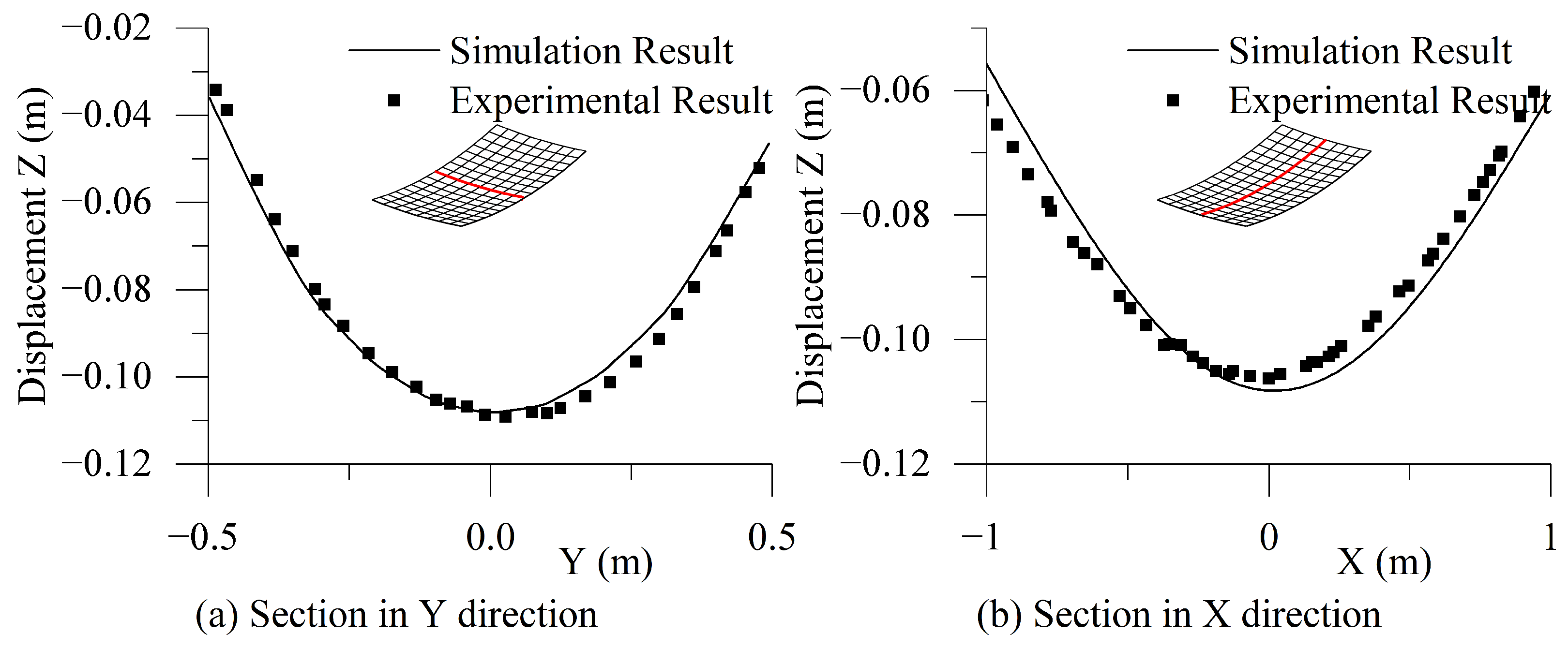
4.4. Results and Discussion
5. Conclusions
Author Contributions
Funding
Institutional Review Board Statement
Informed Consent Statement
Data Availability Statement
Conflicts of Interest
References
- Shen, H.; Wang, H.; Zhou, W. Process modelling in laser forming of doubly-curved sheets from cylinder shapes. J. Manuf. Process. 2018, 35, 373–381. [Google Scholar] [CrossRef]
- Ueda, Y.; Murakawa, H.; Rashwan, A.M.; Kamichika, R.; Ishiyama, M.; Ogawa, J.I. Development of Computer Aided Process Planning System for Plate Bending by Line-Heating (Report IV): Decision Making on Heating Conditions, Location and Direction (Mechanics, Strength & Structural Design). Trans. JWRI 1993, 22, 9. [Google Scholar]
- Ueda, Y.; Murakawa, H.; Ma, N. Welding Deformation and Residual Stress Prevention; Elsevier Butterworth-Heinemann: Burlington, NJ, USA, 2012. [Google Scholar] [CrossRef]
- Chang, X.; Fu, W.; Li, M.; Wang, X. The flexible rolling process of three-dimensional curved parts using an auxiliary plate based on rigid arc-shaped rollers. Int. J. Adv. Manuf. Technol. 2021, 116, 1103–1113. [Google Scholar] [CrossRef]
- Ueda, Y.; Murakawa, H.; Rashwan, A.M.; Okumoto, Y.; Kamichika, R. Development of Computer Aided Process Planning System for Plate Bending by Line Heating (Report I): Relation between the Final Form of Plate and the Inherent Strain (Machanics, Strength & Structural Design). Trans. JWRI 1991, 20, 275–285. [Google Scholar]
- Zhao, Y.; Yuan, H.; Tang, G.; Dong, H.; Hu, C.; Yan, J. Automatic Integral Forming Method for Double-Curvature Plate of Ship. The United States Patent 14/584943, 5 September 2017. [Google Scholar]
- Wang, X.; Shi, Y.; Guo, Y.; Wang, Q. Design of 3D surface laser forming process. J. Manuf. Process. 2022, 73, 306–315. [Google Scholar] [CrossRef]
- Ryu, C.; Shin, J.G. Optimal Approximated Unfolding of General Curved Shell Plates Based on Deformation Theory. J. Manuf. Sci. Eng. 2006, 128, 261–269. [Google Scholar] [CrossRef]
- Zhang, S.; Liu, C.; Wang, X. An optimal flattening algorithm for ship hull plate fabricated by thermal forming. J. Mar. Sci. Technol. 2018, 24, 134–151. [Google Scholar] [CrossRef]
- Lan, H.; Liu, C.; Nie, X. Multi-Objective Optimization Model for Expansion Method of Three-Dimensional Curved Hull Plate. Shanghai Jiaotong Daxue Xuebao/J. Shanghai Jiaotong Univ. 2020, 54, 1101–1107. [Google Scholar] [CrossRef]
- Chapelle, D.; Bathe, K.J. The Finite Element Analysis of Shells-Fundamentals, 2nd ed.; Computational Fluid and Solid Mechanics; Springer: Berlin/Heidelberg, Bermany, 2011. [Google Scholar] [CrossRef]
- Dvorkin, E.N.; Bathe, K.J. A continuum mechanics based four-node shell element for general nonlinear analysis. Eng. Comput. 1984, 1, 77–88. [Google Scholar] [CrossRef] [Green Version]
- Ambartsumyan, S.A. Basic equations and relations in the theory of anisotropic bodies with different moduli in tension and compression. Inzh. Zhur. MTT 1969, 3, 51–61. [Google Scholar]
- Ambartsumyan, S.A. Elasticity Theory of Different Moduli; China Railway Publishing House: Beijing, China, 1986. [Google Scholar]
- Tabaddor, F. Two-Dimensional Bi-Linear Orthotropic Elastic Materials. J. Compos. Mater. 2016, 3, 725–727. [Google Scholar] [CrossRef]
- Jones, R.M. Buckling of circular cylindrical shells with different moduli in tension and compression. AIAA J. 1971, 9, 53–61. [Google Scholar] [CrossRef]
- Jones, R.M. Mechanics of Composite Materials; McGraw-Hill: New York, NY, USA, 1975. [Google Scholar]
- Itskov, M. Tensor Algebra and Tensor Analysis for Engineers (Second Edition): With Applications to Continuum Mechanics; Springer: Berlin/Heidelberg, Germany, 2009; pp. 1–247. [Google Scholar] [CrossRef]
- He, X.t.; Zheng, Z.l.; Sun, J.y.; Li, Y.m.; Chen, S.l. Convergence analysis of a finite element method based on different moduli in tension and compression. Int. J. Solids Struct. 2009, 46, 3734–3740. [Google Scholar] [CrossRef] [Green Version]
- Bathe, K.J.; Dvorkin, E.N. A four-node plate bending element based on Mindlin/Reissner plate theory and a mixed interpolation. Int. J. Numer. Methods Eng. 1985, 21, 367–383. [Google Scholar] [CrossRef]
- Shim, D.; Yang, D.; Chung, S.; Han, M. Optimization of forming steps in the incremental forming of twisted shapes using a line array roll set (LARS). Int. J. Precis. Eng. Manuf. 2010, 11, 715–723. [Google Scholar] [CrossRef]
- Dong, H.; Zhao, Y.; Yuan, H.; Hu, X.; Yang, Z. A Simplified Calculation Method of Heat Source Model for Induction Heating. Materials 2019, 12, 2938. [Google Scholar] [CrossRef] [Green Version]
- Dong, H. Scheme Generating Method and Experiment Verification of Cold and Hot Loading for Forming Curved Plates of Ship. Ph.D. Thesis, Huazhong University of Science & Technology, Wuhan, China, 2020. [Google Scholar]
- ABAQUS. ABAQUS Analysis User’s Manual; ABAQUS: Providence, RI, USA, 2015. [Google Scholar]


| Case | Radius after Flattening | Change Relative to the Original Arc Length (%) | The Radius of the Compressive Area | Maximum Membrane Strain | Minimum Membrane Strain | |
|---|---|---|---|---|---|---|
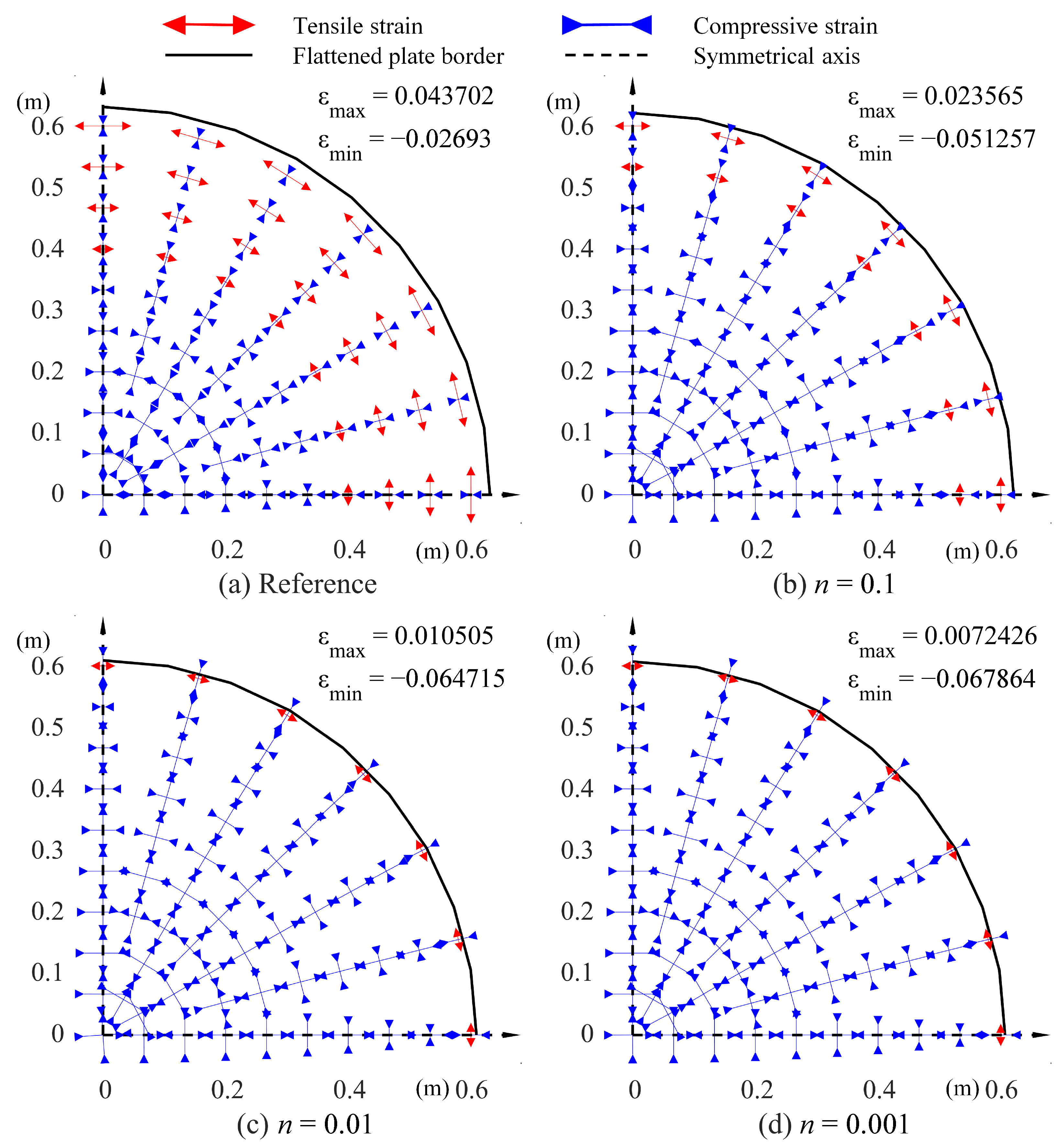
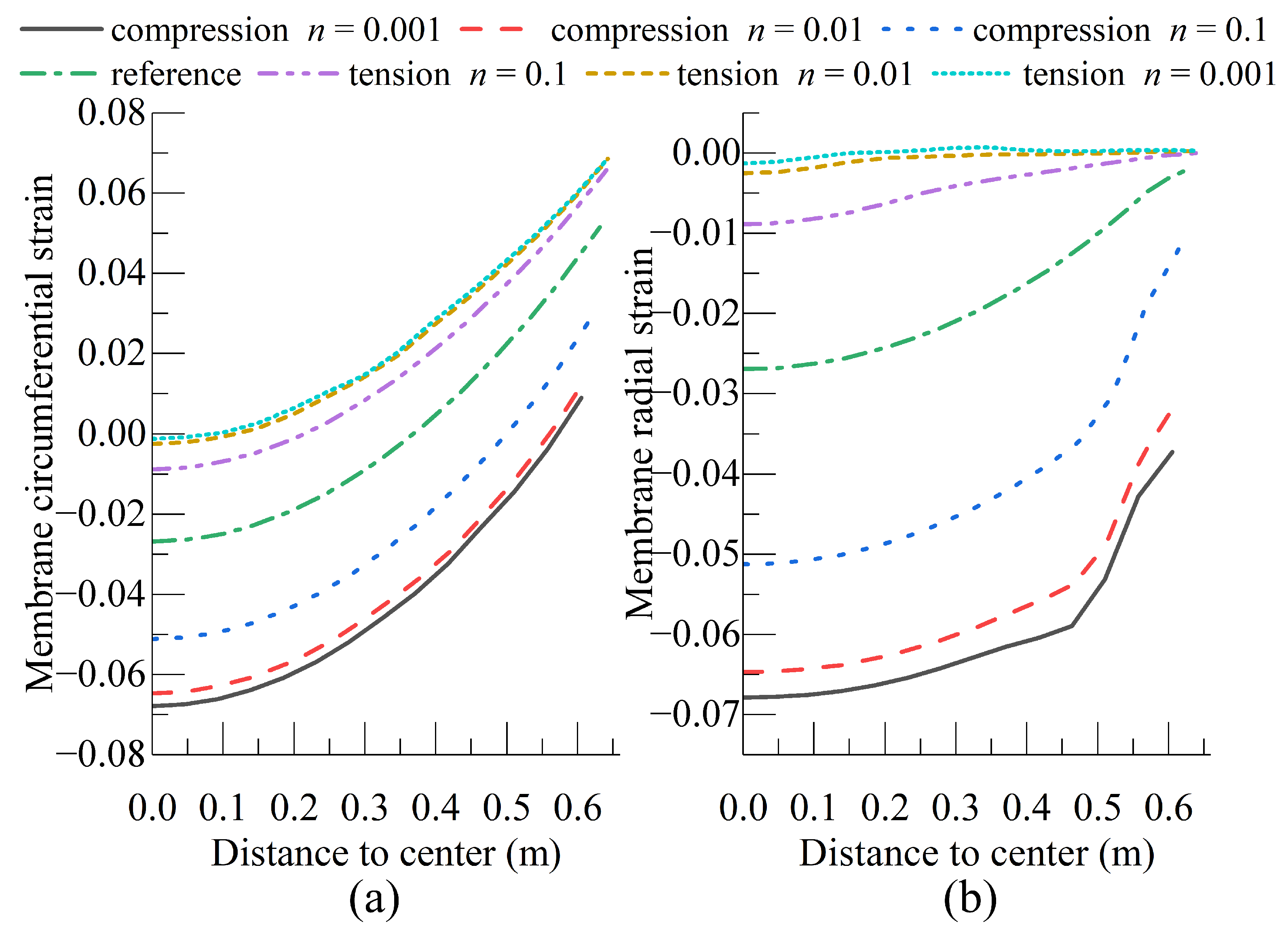
| Compressive | n = 0.001 | 0.606 | −5.9 | 0.606 | 0.0072 | −0.0679 |
| n = 0.01 | 0.608 | −5.5 | 0.608 | 0.0105 | −0.0647 | |
| n = 0.1 | 0.618 | −4.0 | 0.577 | 0.0236 | −0.0512 | |
| Reference | 0.632 | −1.7 | 0.451 | 0.0437 | −0.0269 | |
| Tensile | n = 0.1 | 0.641 | −0.4 | 0.266 | 0.0565 | −0.0089 |
| n = 0.01 | 0.644 | 0.0 | 0.143 | 0.0601 | −0.0025 | |
| n = 0.001 | 0.644 | 0.1 | 0.103 | 0.0611 | −0.0013 | |
| Case | Edge Length X Direction (m) | Edge Length Y Direction (m) | Maximum Membrane Strain () | Minimum Membrane Strain () | |
|---|---|---|---|---|---|
| Pillow | Reference | 2.0366 | 1.0034 | 4.37 | −2.32 |
| Tensile strain | 2.0394 | 1.0045 | 6.17 | −0.14 | |
| Tensile strain X dir | 2.0427 | 1.0019 | 6.86 | −0.12 | |
| Tensile strain Y dir | 2.0325 | 1.0161 | 22.39 | −0.93 | |
| Saddle | Reference | 1.9989 | 1.0054 | 1.56 | −2.87 |
| Tensile strain | 2.0025 | 1.0065 | 3.96 | −0.17 | |
| Tensile strain X dir | 2.0023 | 1.0064 | 4.67 | −0.24 | |
| Tensile strain Y dir | 2.0006 | 1.0053 | 10.27 | −1.74 | |
| Ueda’s Result | This Paper | |
|---|---|---|
| Maximum bending strain | 2.98 | 2.82 |
| Minimum bending strain | −9.77 | −9.67 |
| Minimum membrane strain | −2.07 | −2.06 |
| Mises stress with inherent strain distributed (MPa) | 9.28 | 1.37 |
| Desired Shape | Distributed Inherent Strain (Ueda’s Result) | Distributed Inherent Strain (This Paper) | |
|---|---|---|---|
| (mm) | 30.0 | 29.98 | 29.77 |
| (mm) | −40.0 | −39.64 | −40.00 |
Disclaimer/Publisher’s Note: The statements, opinions and data contained in all publications are solely those of the individual author(s) and contributor(s) and not of MDPI and/or the editor(s). MDPI and/or the editor(s) disclaim responsibility for any injury to people or property resulting from any ideas, methods, instructions or products referred to in the content. |
© 2023 by the authors. Licensee MDPI, Basel, Switzerland. This article is an open access article distributed under the terms and conditions of the Creative Commons Attribution (CC BY) license (https://creativecommons.org/licenses/by/4.0/).
Share and Cite
Chang, L.; Zhao, Y.; Yuan, H.; Wei, Z. A Curved Plate-Flattening Method to Construct the Membrane Strain Distribution. J. Mar. Sci. Eng. 2023, 11, 439. https://doi.org/10.3390/jmse11020439
Chang L, Zhao Y, Yuan H, Wei Z. A Curved Plate-Flattening Method to Construct the Membrane Strain Distribution. Journal of Marine Science and Engineering. 2023; 11(2):439. https://doi.org/10.3390/jmse11020439
Chicago/Turabian StyleChang, Lichun, Yao Zhao, Hua Yuan, and Zhenshuai Wei. 2023. "A Curved Plate-Flattening Method to Construct the Membrane Strain Distribution" Journal of Marine Science and Engineering 11, no. 2: 439. https://doi.org/10.3390/jmse11020439