1. Introduction
The development of marine engineering is very important for the development and utilization of marine resources [
1,
2]. At present, China’s marine development of shoals and offshore areas has continued to increase, and jacket foundations have been widely used, due to their advantages such as a simple structure, safety and reliability, low cost, and little influence by waves and current loads [
3,
4,
5,
6]. The Bohai Sea, the Yellow Sea, and the southeast coast of China are earthquake-prone areas [
7,
8]. In addition to typical wind, waves, and current loads, offshore marine engineering construction in China also faces the potential threat of seismic loads [
9].
A seabed earthquake has strong uncertainty and randomness. The seismic action will affect the mechanical behavior of each component of the offshore platform itself and between the components, resulting in a change in the vibration response of the platform structure. A seismic primary wave will affect the vertical vibration response of the structure. The jacket platform has dynamic sensitivity, and it is prone to excessive multi-modal vibration under complex seismic loads, which greatly affects the daily operation of offshore platforms and may cause structural fatigue damage [
10,
11,
12]. In order to ensure the safe and reliable operation of an offshore platform, it is necessary to control the vibration of the offshore platform under load to prolong the service life of the platform and reduce the maintenance cost of the platform [
13]. Passive energy dissipation technology has been widely used in the field of marine engineering due to its economy, effectiveness, reliability, and easy implementation [
14,
15].
Ke et al. [
16] studied the effectiveness of a shape memory alloy and wedge friction plate self-centering damper (SMA-VFSD), with multiple energy dissipation mechanisms, in improving the seismic performance of structures under seismic loads. The results show that the multiple energy dissipation mechanisms of SMA-VFSDs are beneficial in reducing the inelastic seismic response of structures. Zuo et al. [
17] applied multiple-tuned mass dampers (MTMD) to a fixed offshore platform structure and studied the control effect of the MTMD on structural vibrations under an earthquake by numerical simulation. Wang et al. [
18] used the amplified damping transmission system (ADTS) to control the vibration of the jacket platform under an earthquake. The results show that compared with the traditional mass damper (TMD), ADTS has better performance in controlling seismic responses due to its higher additional damping. Zhang et al. [
19] proposed a tuned mass damper (TMDI) to reduce the vibration of offshore platforms under wind–wave–earthquake combined loads. The results show that TMDI is superior to TMD in suppressing wind–wave–earthquake coupling response. The above energy dissipation structures are mainly used to suppress the horizontal vibration response of marine structures under earthquake action, while the vertical vibration response of marine structures should not be ignored.
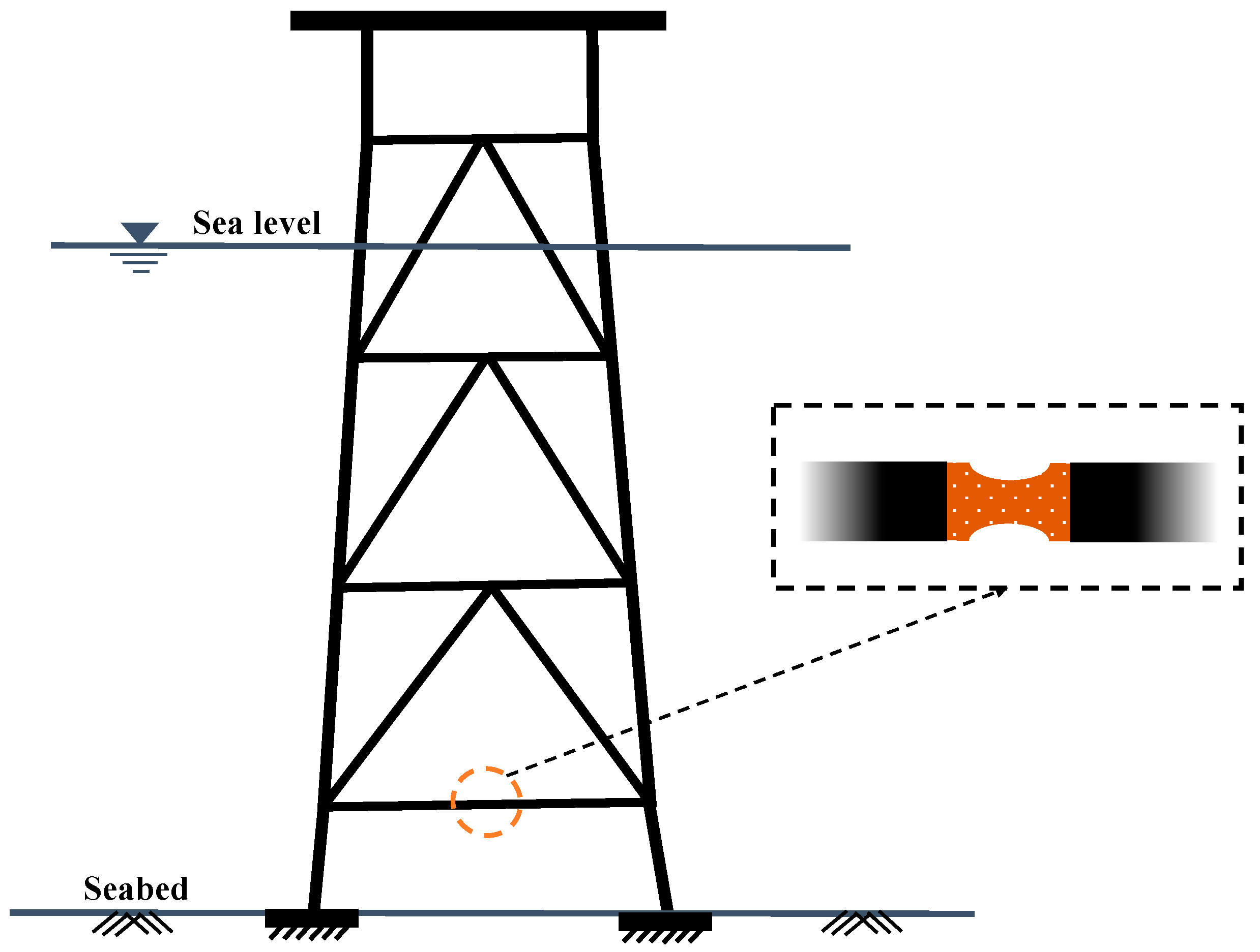
At present, the shear plate metal damper is usually used to control the vertical vibration of the structure, and the opening form of the damper will directly affect the energy dissipation efficiency of the damper. The stress concentration of the shear plate metal damper in the traditional opening form is more severe, resulting in poor energy dissipation capacity. Based on this, this paper proposes a new type of shear plate metal damper, which is a shear plate metal damper with upper and lower elliptical openings. The new damper is arranged in the middle of the horizontal brace, as shown in
Figure 1. It can first yield to dissipate energy under a seismic load, effectively reduce the vertical vibration response of the structure caused by the primary wave, and protect the safety of the whole structure. The new shear plate metal damper mainly uses the plastic deformation of structural components to dissipate seismic energy. It not only has superior energy dissipation performance [
20,
21] but also has the advantages of a simple structure, low cost, and easy replacement after damage [
22]. It can effectively reduce the damage to the jacket platform caused by the seismic load and the maintenance cost of the platform after the earthquake.
In this paper, a new type of shear plate metal damper with upper and lower elliptical openings suitable for jacket platforms is proposed and compared with the other three traditional opening forms (central elliptical opening, single row opening, and double row opening). The energy dissipation performance of the new shear plate metal damper is explored by loading test. The section of this paper is divided into the following four parts:
Section 2 shows the experimental basis;
Section 3 comprises the performance study of the new damper;
Section 4 presents the conclusion and future of this paper.
2. Test Basis
2.1. Shear-Type Steel Plate Damper Selection
- (1)
Entire plate without opening form
Because the damper is sheared as a whole, the bending movement at both ends is the largest, so the stress at both ends of the shear plate is the largest, and stress concentration can occur easily, resulting in premature failure of the damper.
- (2)
Centralized opening form
Centralized opening refers to the form in which the openings are concentrated and the position edges are closed. This form is widely used in dampers with steel as the matrix. The opening position is usually the shear web, the opening is generally an approximate diamond, and the diamond is circularly transitioned to avoid stress concentration. The diamond opening is to enable the web to yield most of the energy consumption and enhance the energy dissipation capacity of the damper. The reasonable yield order is that the weakest section yields first, and the strength of the material is hardened to achieve the purpose of yielding most of the web. Such dampers are generally designed as shear-yielding energy dissipation components. Even so, the failure of most metal dampers in the form of central diamond openings is also due to an improper opening size or angle, resulting in cracking failure at the diamond corner position on the web.
- (3)
Distributed opening form
Distributed opening refers to the dispersed opening form located inside or at the edge of the damper. This kind of damper is combined with each others in terms of the number of openings, the style of openings, the location of openings, and the various configurations of the damper matrix, which can form a variety of distributed opening forms. The more common forms include single-row openings and multi-row openings. A distributed opening damper has better energy dissipation capacity and more uniform plastic distribution. In recent years, scholars at home and abroad have done considerable research on the above two forms of shear plate dampers and put forward a large number of open-hole configurations.
In summary, this paper proposes a shear plate damper configuration in the form of upper and lower elliptical openings. This form also belongs to the distributed opening form. The elliptical opening avoids the generation of stress concentration to the greatest extent. At the same time, it has the advantages of simple configuration and convenient industrial processing.
2.2. Shear Steel Damper with Different Opening Forms
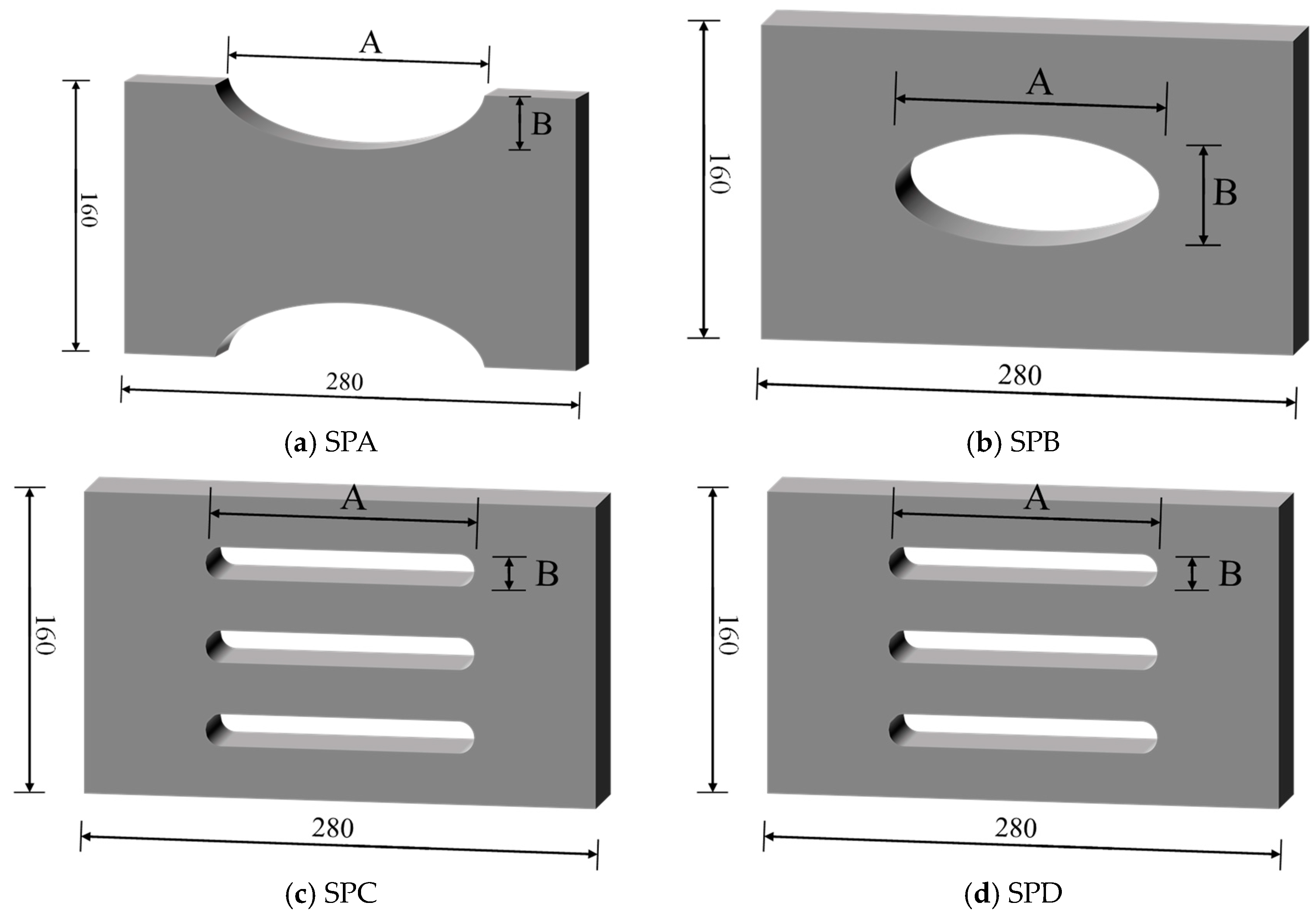
The four forms of shear plate damper configurations are introduced as follows. The specific design parameters are shown in
Table 1:
- (1)
The form of upper and lower elliptical openings: the shear plate is open with a semi-elliptical hole, and the ratio of the long axis to the short axis is 2:1, which is recorded as SPA (Shear Plate A), as shown in
Figure 2a.
- (2)
The form of the central elliptical hole: the central elliptical hole of the shear plate is recorded as SPB (Shear Plate B), as shown in
Figure 2b.
- (3)
Single-row opening form: the shear plate has dispersed single-row openings, and the end of the hole groove is designed as a circle, which is recorded as SPC (Shear Plate C), as shown in
Figure 2c.
- (4)
Double-row opening form: The shear plate has dispersed double-row openings, and the end of the hole groove is designed as a circle, which is recorded as SPD (Shear Plate D), as shown in
Figure 2d.
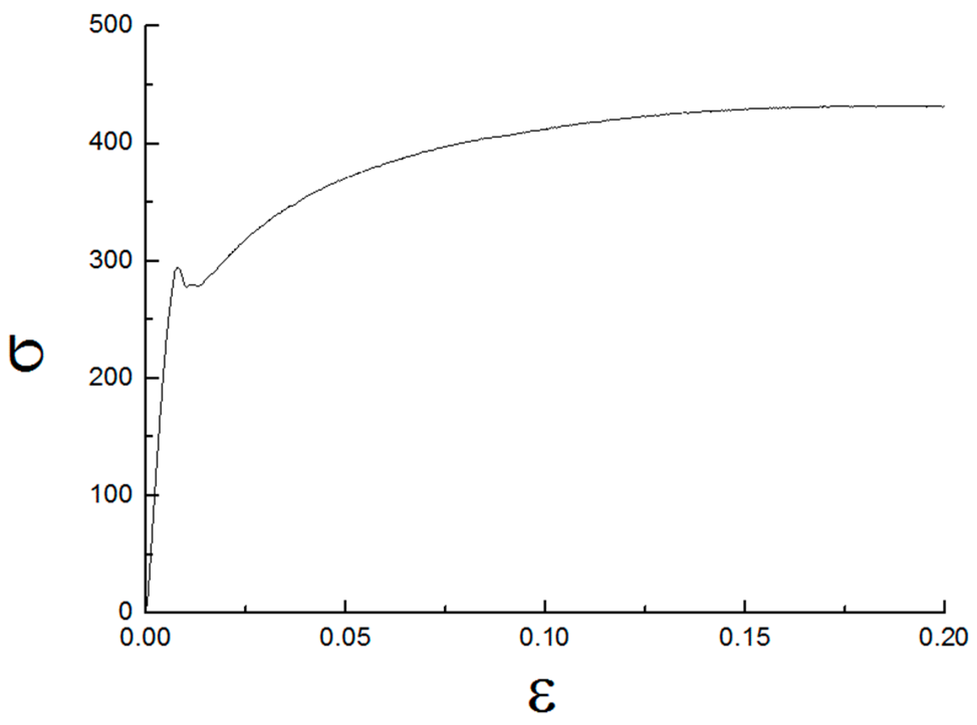
2.3. Constitutive Relationship of Materials
The four kinds of damper materials are all Q235 steel, and their physical and mechanical properties are shown in
Table 2, where
ρ is the material density,
E is the elastic modulus,
μ is the Poisson’s ratio,
C is the specific heat capacity,
σb is the ultimate strength, and
σy is the yield strength. In order to obtain the actual yield strength of the material, the tensile test of the standard specimen of the same batch of steel was carried out. The material’s constitutive relationship is shown in
Figure 3, where
σ is stress, and
ε is strain.
2.4. Test Equipment
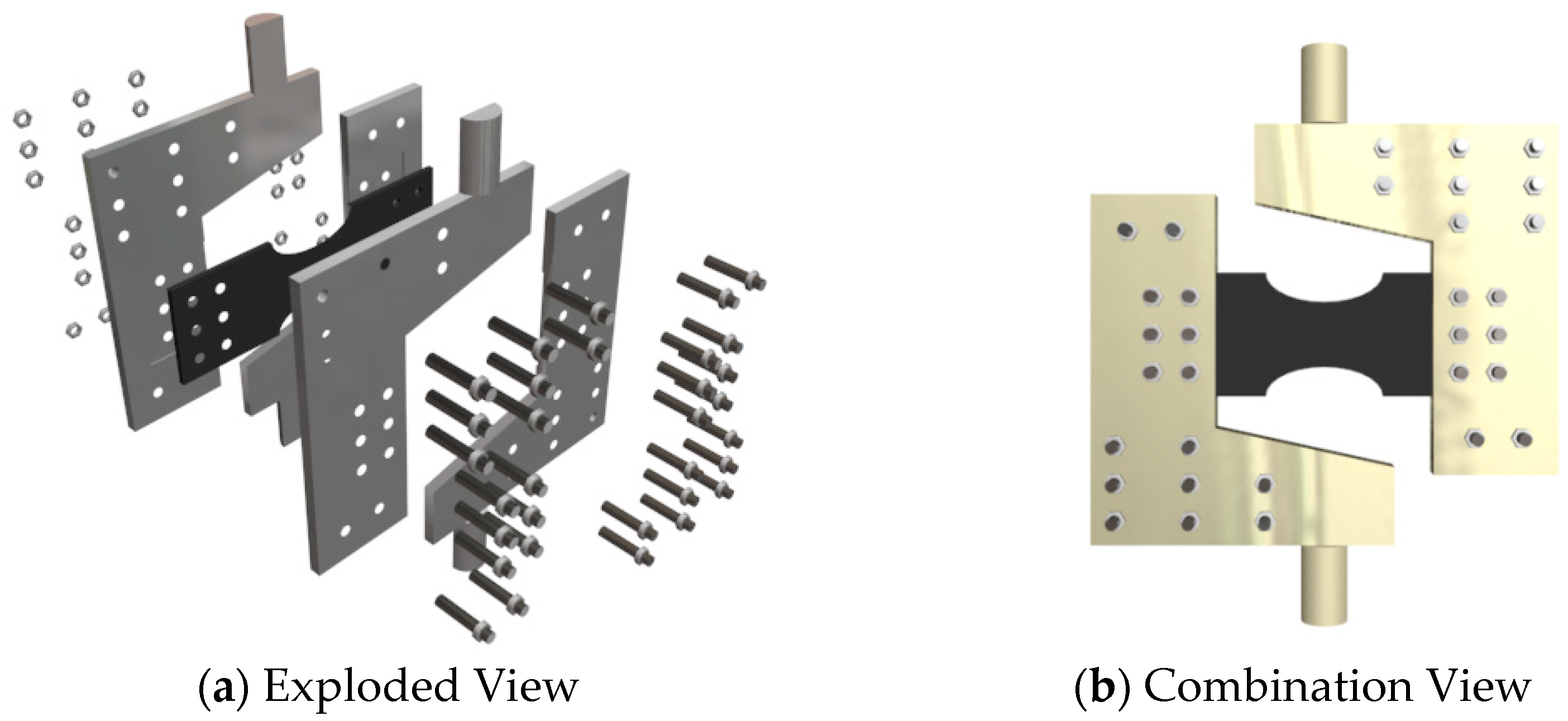
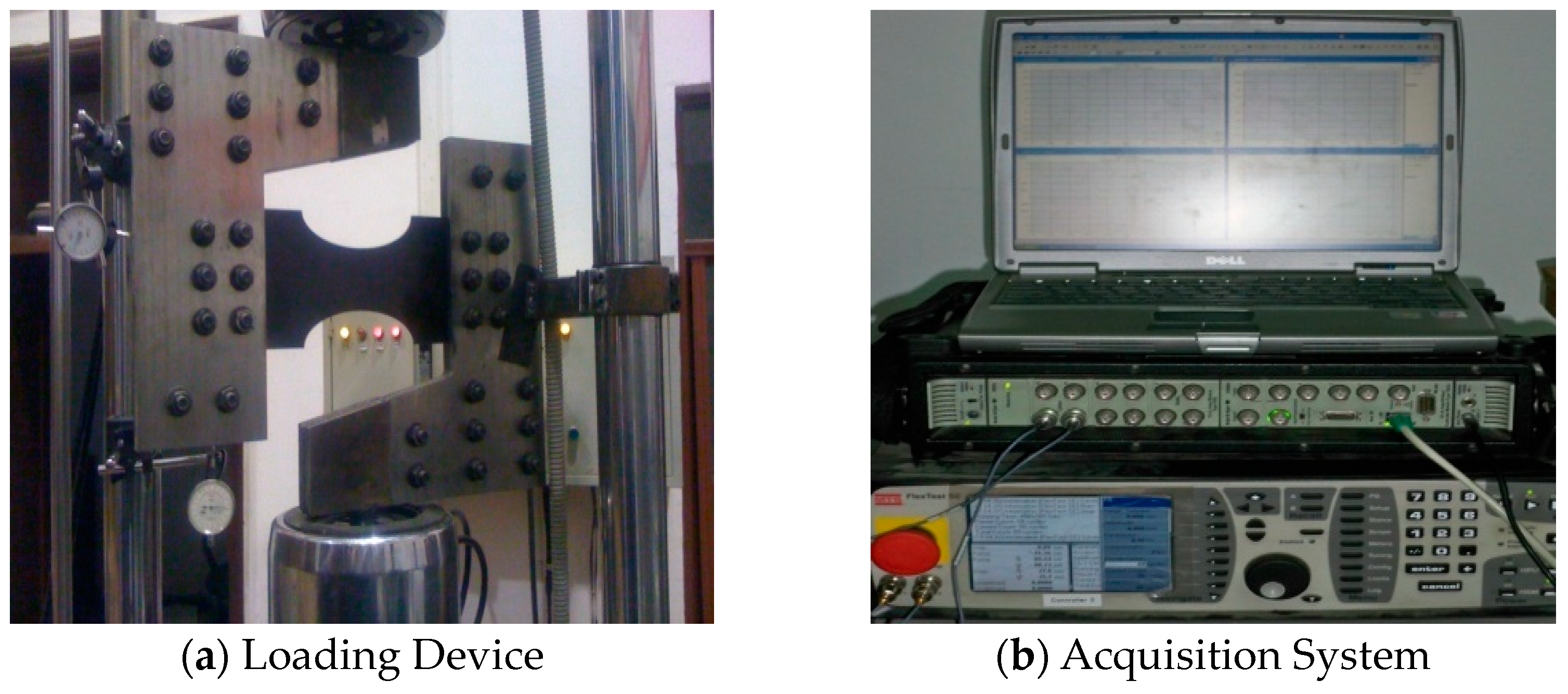
In this paper, the loading test of the specimen is carried out by using a 30 t MTS testing machine. The load range of the test machine is ±30 KN (large sensor) and ±1 KN (small sensor), the load accuracy is ±0.5%, the maximum displacement is 1000 mm, and the control mode is displacement and load. The fixture is a double-layer antisymmetric L-shaped bracket with a single-layer thickness of 20 mm. The yield strength of the material is about 235 MPa and the ultimate strength is 406 MPa. The two ends of the component are tightened with the fixture through 12 high-strength bolts. The double-layer fixture is connected by 20 high-strength bolts, and the component is held at the center of the fixture. The upper and lower ends of the fixture are welded with holding rods with a diameter of 36 mm, as shown in
Figure 4.
The upper and lower ends of the loading frame are connected with the MTS testing machine, and the fixture transforms the tensile loading into the shear loading of the component, as shown in
Figure 5a. The shear reciprocating loading test of the coupling beam damper is realized by the axial reciprocating loading test of the upper actuator of MTS.
The loading frame has enough stiffness to satisfy the full transfer of the loading displacement to the damper end. During the experiment, two dial gauges were placed at the end of the loading frame to observe the horizontal displacement and vertical displacement of the loading frame, respectively. The results show that the displacement generated is very small and can be ignored relative to the loading displacement. The test data is collected by the test machine’s own acquisition system, as shown in
Figure 5b.
3. Study of the Performance of the New Damper
In this section, the hysteretic curves, skeleton curves, and energy dissipation performance indexes of the four kinds of shear plate metal dampers (SPA, SPB, SPC, and SPD) with different opening forms are calculated. The purpose is to explore the anti-vibration performance of the new shear plate metal damper (SPA), with upper and lower elliptical openings, under the action of seismic primary waves.
3.1. Damper Loading Deformation and Failure Modes
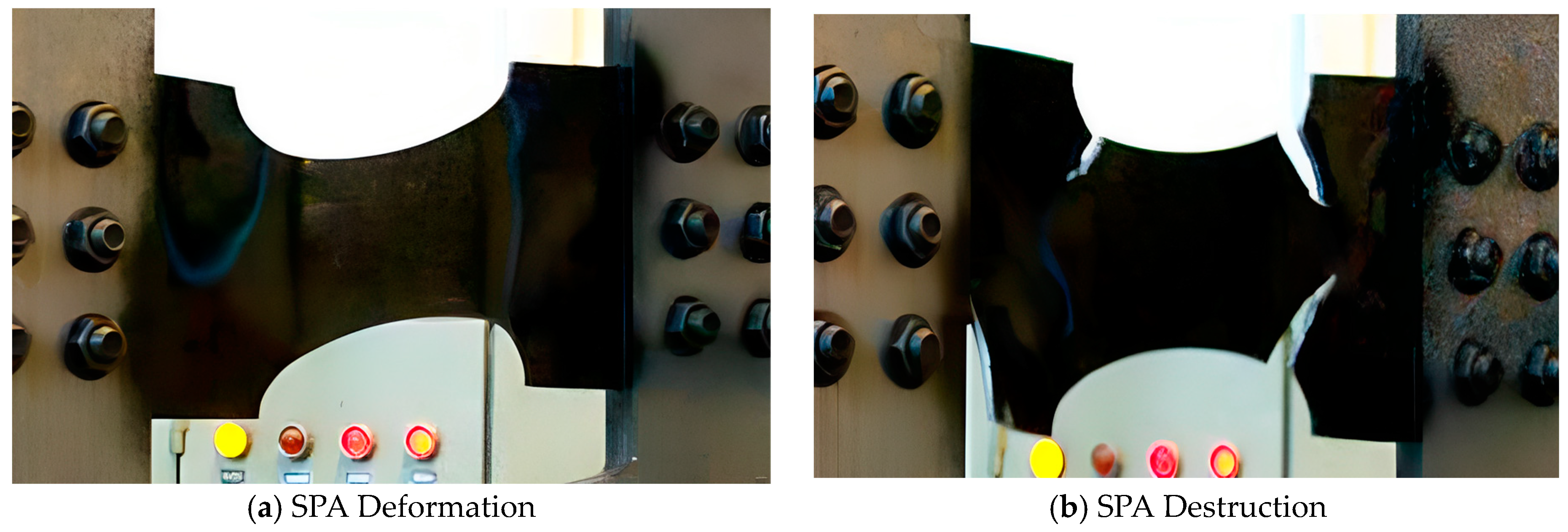
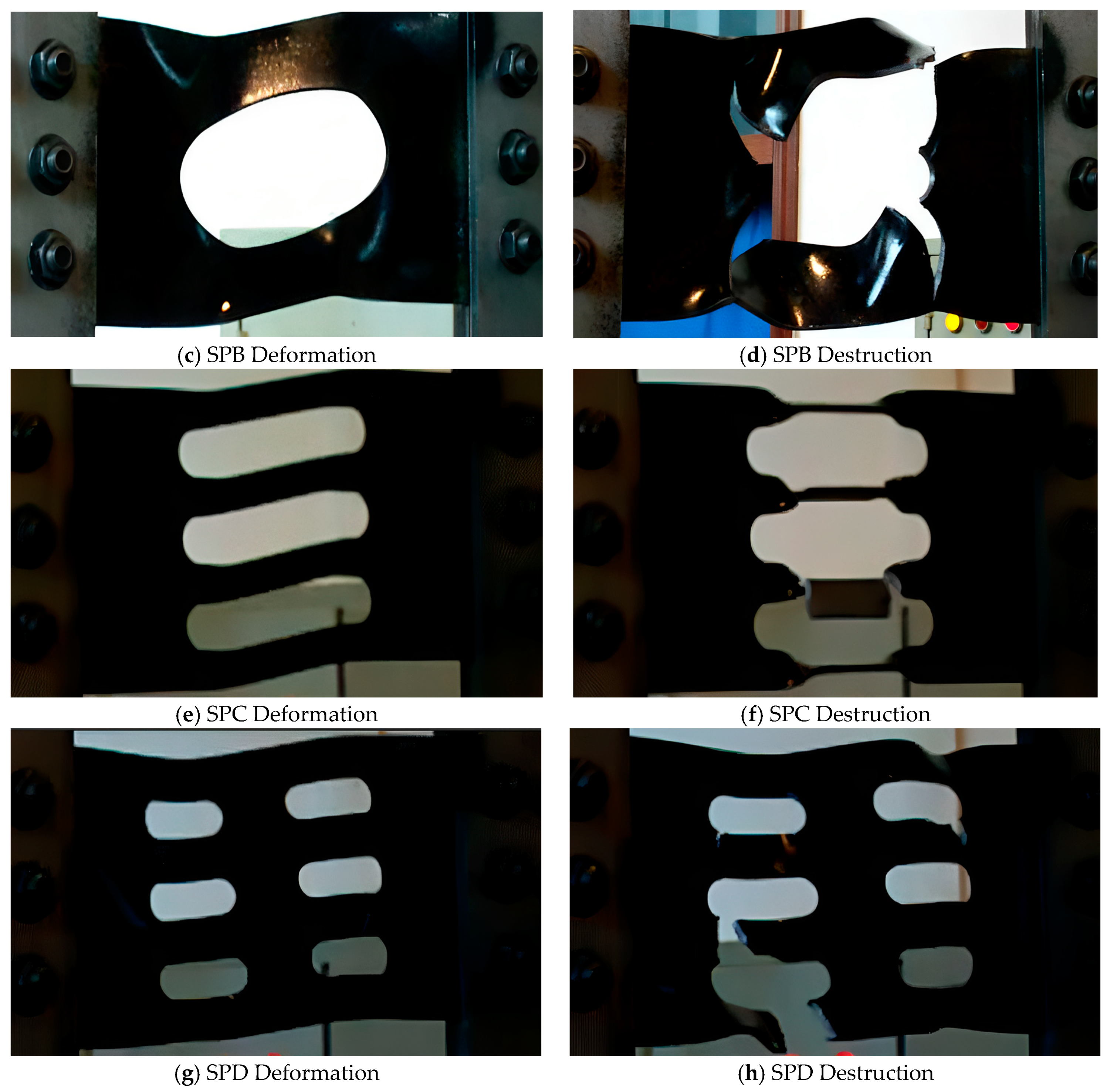
Taking the opening rate of 25% as an example,
Figure 6 lists the loading deformation and failure modes of the four kinds of shear plate dampers with openings. The deformation diagram corresponds to the deformation of the shear plate when it reaches the peak shear force. It can be seen from
Figure 6 that the overall yield phenomenon of the four types of shear plates is obvious. The form of deformation in
Figure 6 shows that SPA, SPB, and SPD have a certain overall out-of-plane phenomenon, while SPC has a local out-of-plane phenomenon due to the small center stiffness, but the overall planeness is good.
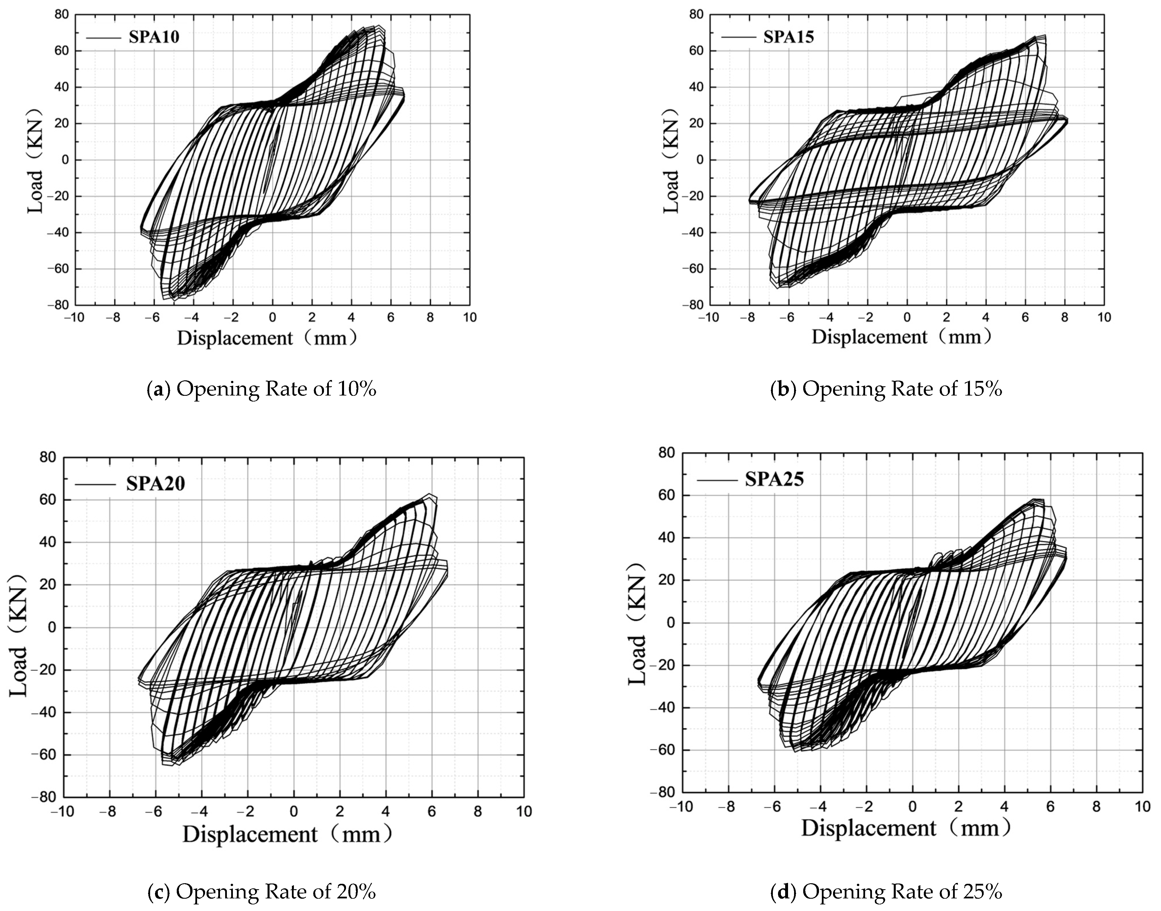
3.2. Load-Displacement Hysteretic Curve
In order to better compare the hysteresis performance of different forms of shear plate dampers, the abscissa of the hysteresis curve uses the shear displacement angle, and the ordinate uses the measured shear load. The hysteresis curves of the four types of shear plate dampers with four opening rates are obtained, as shown in
Figure 7,
Figure 8,
Figure 9 and
Figure 10.
Figure 7 shows the hysteresis curve of the SPA series shear plate damper. It can be seen from the figure that the shape and change trend of the hysteresis curve under different opening rates are basically the same, and the secondary stiffness increases significantly after loading 1 mm displacement. The peak shear force of the damper decreases with the increase in the opening rate. The peak shear force of SPA10 is 74.22 KN, and the peak shear force of SPA15 is equivalent to it. The peak shear force of SPA20 and SPA25 decreased obviously, about 60 KN, which was 80% of the peak shear force of SPA10. At the same time, it can be seen that the bearing capacity of SPA series dampers after failure is between 30 KN and 40 KN, which decreases to about half of the peak shear force. From the point of view of the failure mode, the upper and lower sides of the central area of the shear plate are first torn along the inclined 45° direction, the central connection area provides some residual stiffness, and the bearing capacity before and after yield is quite different.
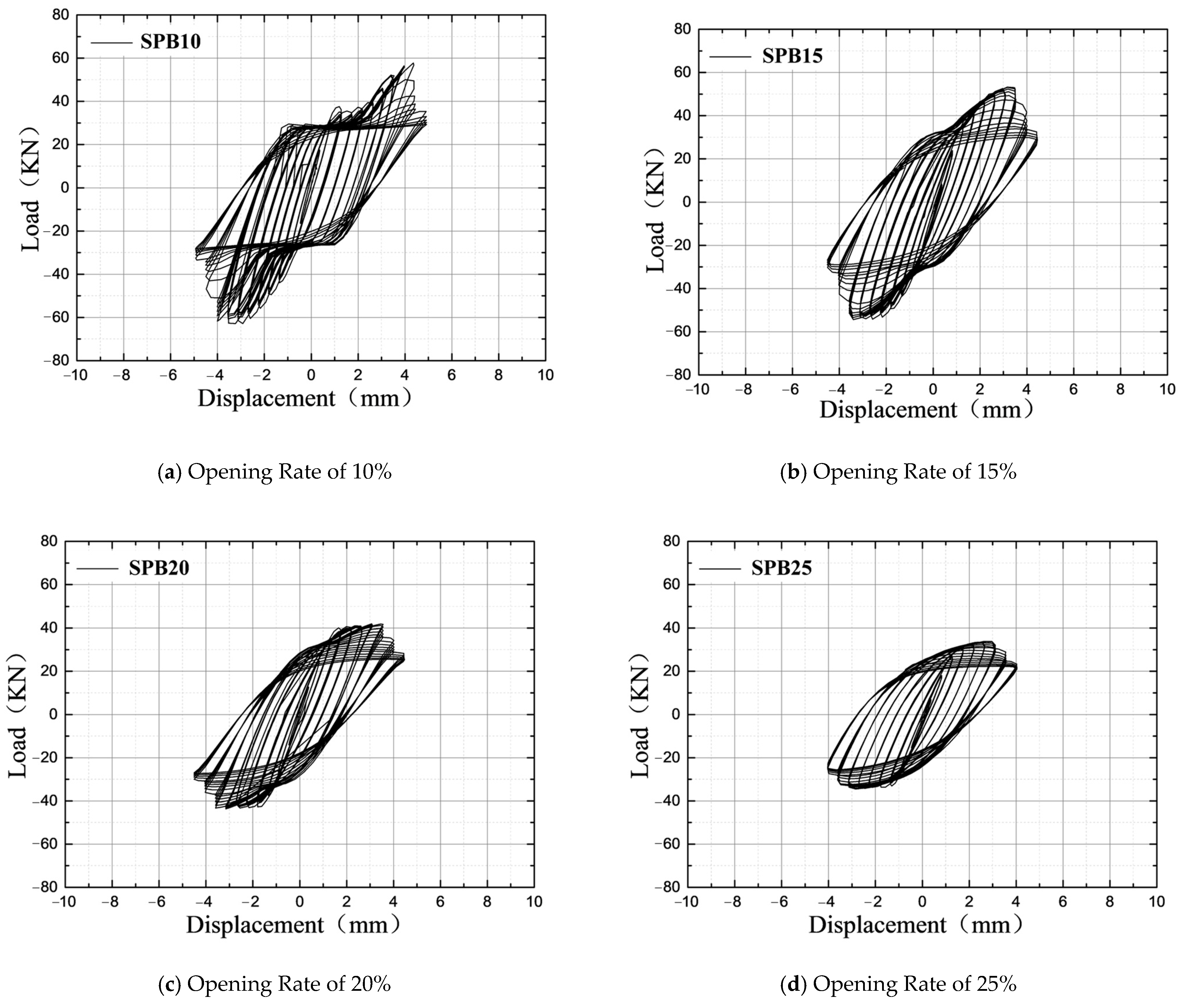
Figure 8 shows the hysteresis curve of the SPB series shear plate damper. It can be seen in the figure that the shape and change trend of the hysteresis curves of SPB15, SPB20, and SPB25 are basically the same, while the hysteresis curve of SPB10 after failure is fuller than that of the other three forms of opening rate. The peak shear force is 58.77 KN, which is basically the same as the peak shear force of SPB15. The peak shear force of SPB25 is 33.86 KN, which is about 58% of the peak shear force of SPB10. The bearing capacity of the SPB series dampers after failure is between 20 KN and 30 KN. From the perspective of the failure mode, the central area of the shear plate (corresponding to the same area as SPA) is torn up and down along the inclined 45° direction. After short-term stiffness strengthening, the structure fails, and the bearing capacity before and after yield is also quite different.
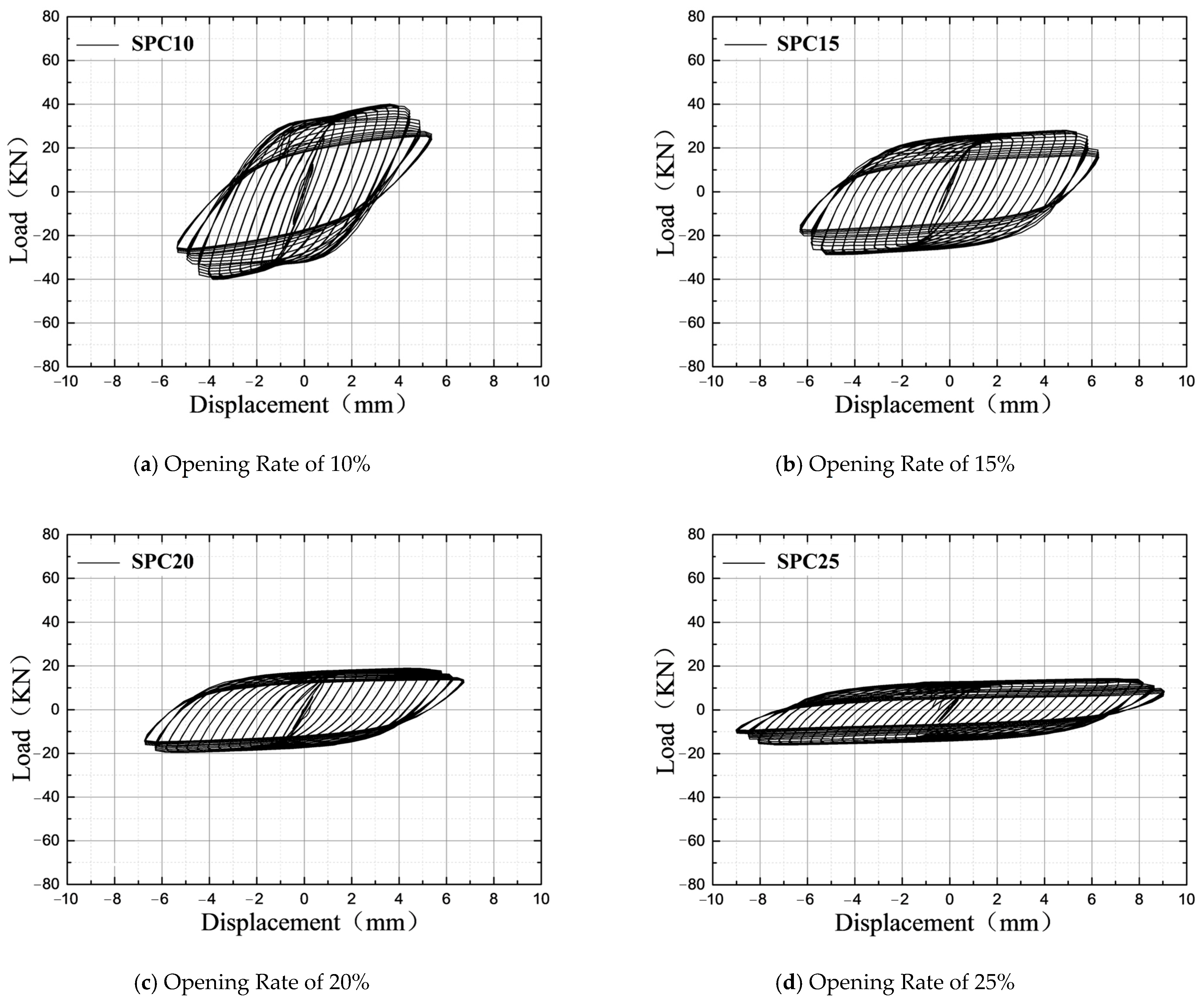
Figure 9 shows the hysteresis curve of the SPC series shear plate damper. In
Figure 9, it can be seen that the hysteresis curve shape of the SPC damper is very full, but the peak shear force is relatively small. Moreover, the larger the opening rate of the damper, the less obvious the secondary stiffness enhancement. At the same time, it can be seen that the difference in the bearing capacity of the SPC series damper with four opening rates after failure is larger than that of the SPA and SPB series, between 15 KN and 40 KN. This is due to the small shear stiffness in the middle of the single-row hole shear plate, which leads to the secondary strengthening that is not obvious. Although it enters the failure state very early, it can be continuously loaded to 9 mm. After the failure, the central line is turned over, and finally, the tear is destroyed and separated from the matrix.
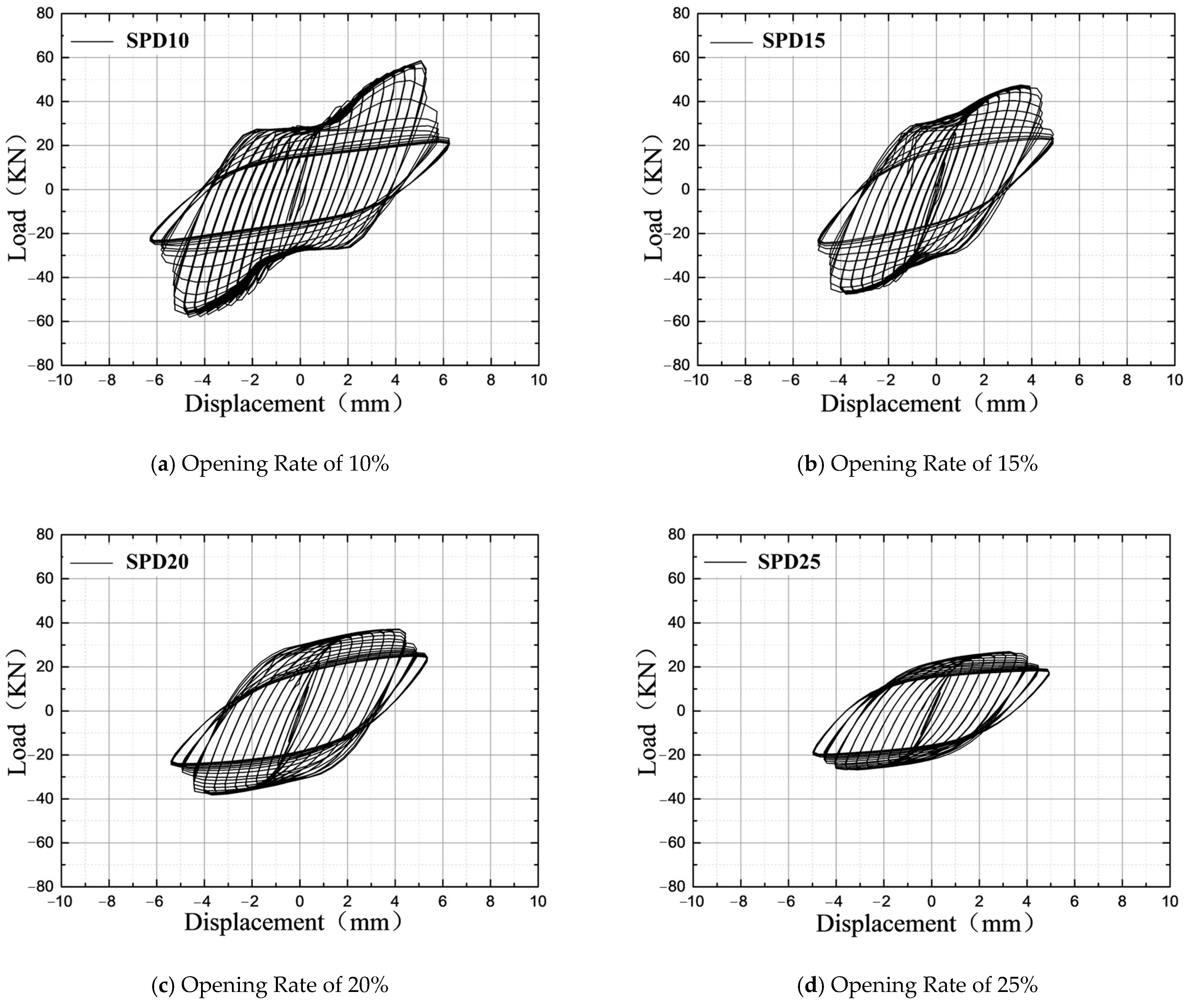
Figure 10 is the hysteresis curve of the SPD series shear plate damper. It can be seen from the diagram that the form and change trend of the SPD hysteresis curve is between the SPA and SPB. When the opening ratio is 15%, the hysteresis curve form of the SPD damper is similar to that of the SPA series. With the increase in the opening ratio, the hysteresis curve form gradually converges to the SPB series. After the failure of the structure, the bearing capacity is maintained at about 20 KN, and the difference in the bearing capacity of the dampers with four opening ratios is not obvious. From the point of view of the failure form, the crack generally starts from the upper and lower edges of one side of the column hole, and the strip begins to damage from the edge of the shear plate. After the failure, the adjacent strips begin to damage, and finally, all the strips on one side are damaged.
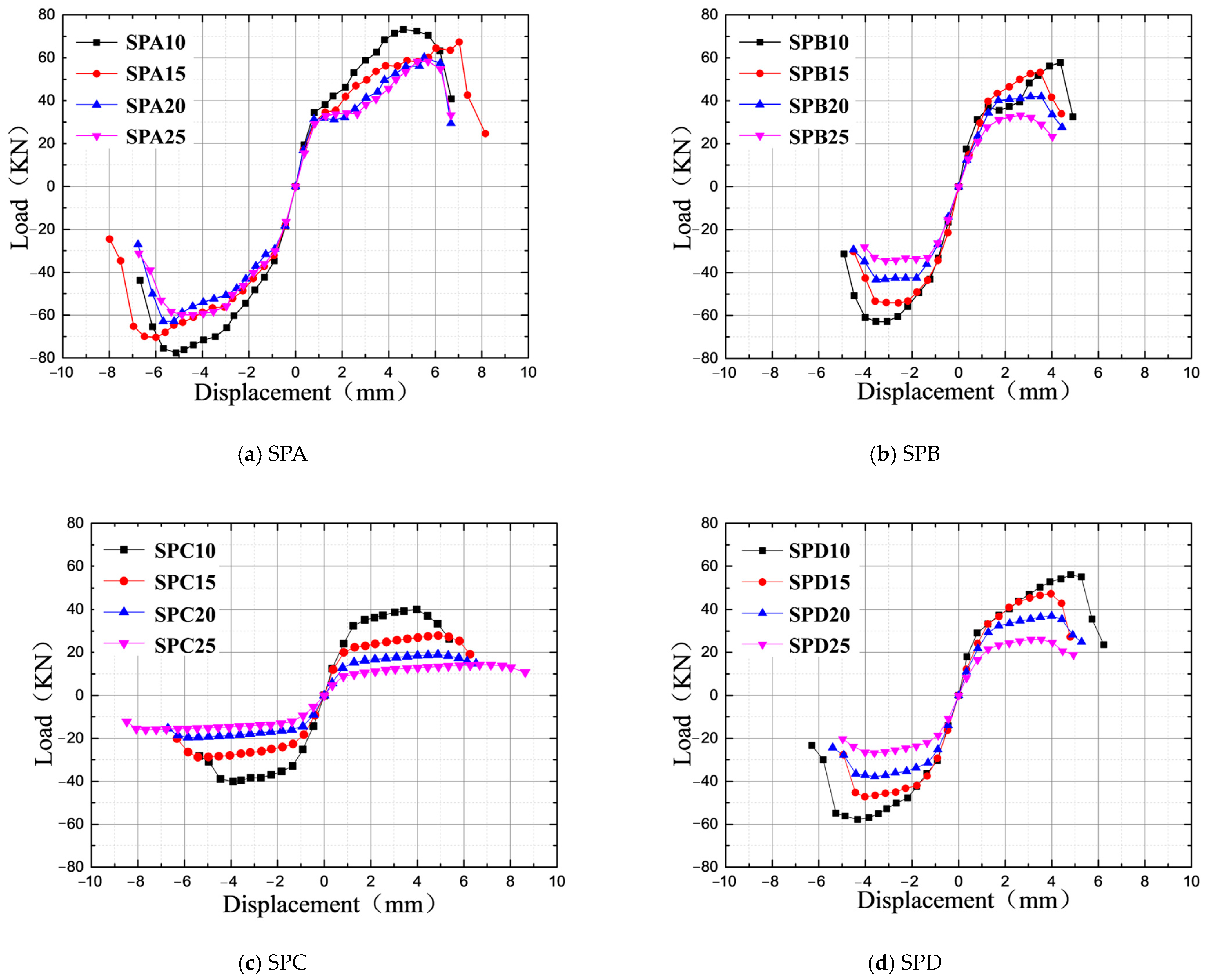
The skeleton curves of the shear plate dampers with different opening forms are shown in
Figure 11. The skeleton curves are typical two-fold lines, and the skeleton curves before yielding are similar to straight lines. The ductility coefficient is generally the ratio of the ultimate displacement to the yield displacement (because the length of each shear plate damper is the same, the ductility coefficient is the ratio of the ultimate shear angle to the yield shear angle). Combined with the hysteresis curves of each shear plate damper, it can be seen that SPA10 yielded the earliest, and its yield shear angle was only 22% of the yield shear angle of SPB15, but its ductility was better. However, it should be pointed out that the reason for the large ductility coefficient is that the yield shear angle is very small. Measured by the ultimate shear angle, although the ultimate shear angle is larger than the other shear plate dampers (except SPC25), once its deformation exceeds the ultimate shear angle, the bearing capacity decreases rapidly, and the peak shear angle is not much different from the ultimate shear angle. On the whole, the SPA series has the highest bearing capacity, the largest peak shear angle, the largest ultimate shear angle, and the highest ductility coefficient.
3.3. Cyclic Hysteretic Energy Dissipation
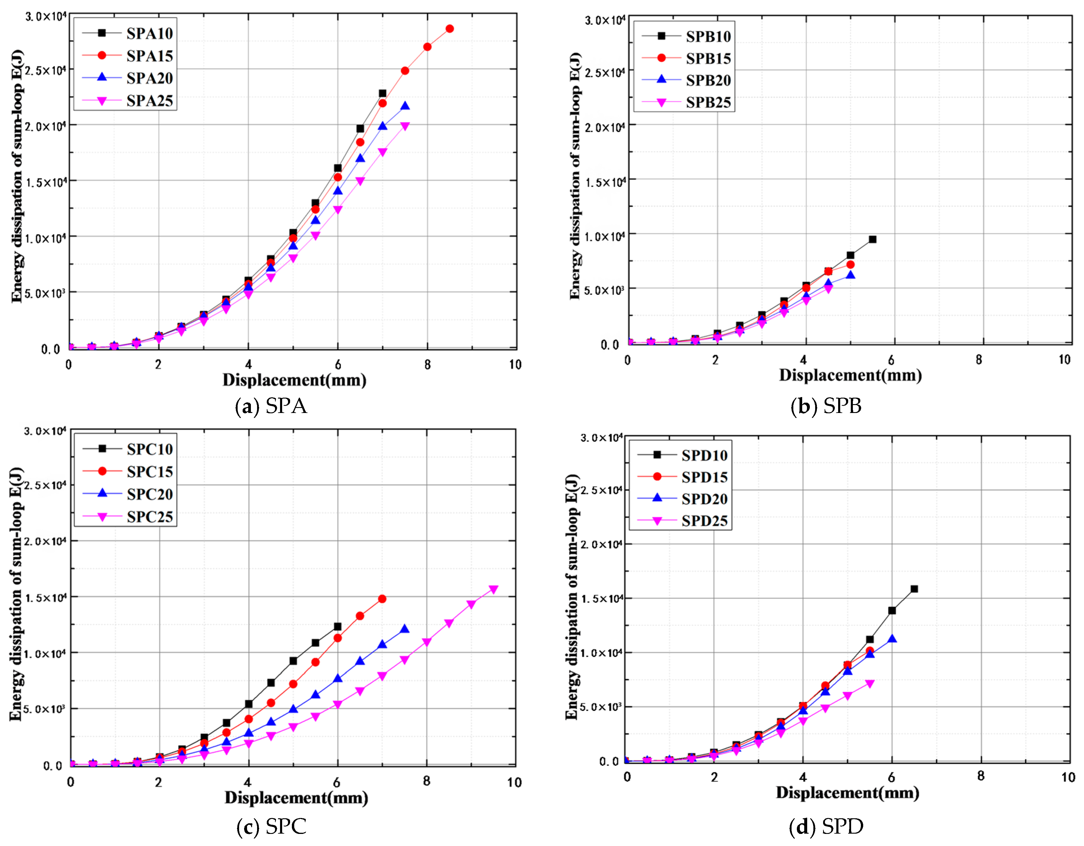
The energy dissipation capacity is an index to measure the anti-vibration performance of the shear plate damper, which reflects the ability of the damper to dissipate energy under reciprocating loading. Taking the hysteresis loop area, ∑E
t, as the energy consumption index, the summary results are shown in
Table 3. Among them, ∑E
t is the area of the hysteresis curve, which represents the hysteretic energy dissipation capacity of the damper. ∑E represents the energy dissipation capacity of the unit volume damper, which is calculated as shown in Formula (1), where φ is the opening ratio of the damper.
Figure 12 lists the hysteretic energy dissipation curves of four types of dampers.
In
Figure 12 and
Table 3, it can be seen that under the same loading amplitude, the smaller the opening rate, the greater the hysteretic energy consumption. Among them, the SPD series 10% and 15% opening rate dampers have similar energy consumption before the 5 mm loading step. SPA15 has the largest energy consumption value in the SPA series, and the 10% opening rate form of SPB and SPD series has the largest energy consumption value. Due to the small stiffness of the SPC series, the larger the opening ratio, the better the ductility, the longer the hysteresis time, and the stronger the energy dissipation capacity. The results show that the energy dissipation performance of SPA series shear plate dampers is better than that of other series dampers.
4. Conclusions and Future
In this paper, the energy dissipation performance of a new type of shear plate metal damper with upper and lower elliptical openings is systematically studied. The hysteretic curve, skeleton curve, and cyclic hysteretic energy dissipation capacity are analyzed by loading tests. The relevant conclusions are as follows:
- (1)
When the opening ratio is 25%, SPA, SPB, and SPD have a certain overall out-of-plane phenomenon, while SPC has a local out-of-plane phenomenon due to the small central stiffness, but the overall planeness is better.
- (2)
The bearing capacity of the SPA series is the highest, and the peak shear force reaches 74.22 KN, which is 19–46% higher than that of the other three dampers (the opening rate is 10%).
- (3)
The bearing capacity and energy dissipation performance of the SPA series shear plate dampers are better than other series dampers, and the energy dissipation capacity is 44–48% higher than the other three dampers (the opening rate is 15%).
In summary, the energy dissipation performance of the SPA series shear plate dampers is better than that of other series dampers, which can solve the problem of excessive vertical vibration of the jacket platform under the action of the seismic primary wave. Through experimental phenomena and theoretical analysis, it can be seen that the SPA series shear plate damper has reasonable force and better performance than other forms of shear plate structure. Moreover, the structure is simple and easy to replace after an earthquake, which has a good application prospect in the seismic field of jacket platforms.
In the future, the author will compare the performance of the new type of shear plate damper with upper and lower elliptical openings proposed in this paper with other available dampers on the market to further verify the performance of the new damper.


