Article

Yard Space Allocation Algorithm for Unloading Containers at Marine Terminals

1
Container Supply Chain Technology Engineering Research Center, Ministry of Education, Shanghai Maritime University, Shanghai 201306, China
2
Shanghai SMUVision Smart Technology Ltd., Shanghai 201306, China
*
Author to whom correspondence should be addressed.
J. Mar. Sci. Eng. 2023, 11(11), 2109; https://doi.org/10.3390/jmse11112109
Submission received: 30 September 2023 / Revised: 31 October 2023 / Accepted: 1 November 2023 / Published: 4 November 2023
(This article belongs to the Special Issue Advances in Marine Logistics, Shipping, and Ports)

Abstract

:
The issue of unloading efficiency for containers is the operational bottleneck for most traditional container terminals. In addressing the intricate challenges of space allocation in container yards during ship unloading, this study focuses on the real-time, dynamic decision-making needs that are currently unmet by existing planning methods. To tackle this, the article introduces a novel model for container space allocation that aims to maximize the “attractiveness” of yard spaces. This model factors in key considerations like the allocation of container handling equipment resources, the rate of container handling equipment traversing the yard, and container handling equipment operations across containers. A unique Monte Carlo tree search (MCTS)-based algorithm is developed to solve this multi-objective problem. The algorithm’s efficacy is rigorously tested via numerical experiments, where it outperforms existing approaches like UCT-MCTS, AMAF-MCTS, and manual scheduling plans using practical engineering examples. This research not only provides a more dynamic and efficient method for yard space allocation but also offers empirical evidence to support its practicality and effectiveness.

1. Introduction

Serving as a critical junction between terrestrial and maritime networks, container terminals are pivotal in the sphere of maritime logistics and transportation. As economic globalization and regional economic integration gain momentum, trade volumes have surged. This uptick in global container freight movement has necessitated the deployment of larger container vessels [1,2]. Simultaneously, the arrival of gargantuan vessels has complicated the daily management of container terminals. Ports are gearing up to tackle the logistical challenges presented by these mega-vessels, some of which have capacities exceeding 20,000 TEU [3].
In light of advancements in science and technology, cutting-edge methodologies encompassing big data analytics and artificial intelligence are increasingly being integrated into the operational frameworks of container terminal management. Digital transformation and automation have become inescapable trends in the realm of yard management [4]. These technological shifts are complemented by an array of new technologies and solutions in logistics transportation, addressing challenges that were historically reliant on manual human intervention. Whether it is monitoring the displacement of the foundation pit [5], positioning the three-dimensional attitude of the container [6], or measuring the position of the container during lifting operation [7], intelligent technology has replaced the traditional manual methods and achieved more accurate, efficient, and automated operations. The selection of an unloading container plan is also such a problem. In the past, it relied on manual planning and deployment, which may fail to consider the mixed stacking of multiple ships and cannot adjust the plan dynamically according to the yard equipment, which may result in the waste of yard resource space to a certain extent. In the case of the relative shortage of yard resources in container terminals, the yard has become a bottleneck in the operation of container terminals. Therefore, it is necessary to study the decision algorithm for selecting the unloading position of container terminals, and achieving intelligent unloading is an inevitable step in the intelligent transformation of container terminals.
The research question of this paper focuses on the algorithm for selecting unloading positions for containers in the port production system. The quality and rationality of this algorithm directly impact the efficiency of loading and unloading operations, making it one of the key points in the intelligent transformation of port production. Specifically, this research aims to dynamically allocate yard positions for unloaded containers via computer automation without the need for manual planning. Taking into account equipment availability, task distribution, and stacking conditions, the system assigns yard positions based on stacking principles [8]. The objective is to reduce the operational costs of terminal yards, overcome the limitations of traditional manual planning for unloading and stacking, and thus effectively improve the utilization rate of both spatial and mechanical resources in terminal yards.
The contributions of this paper include the following aspects: This paper takes into account the current unloading operation in terminals, follows the selection of yard equipment, and proposes a yard container space allocation model with the goal of maximizing the attractiveness of container spaces. Due to the complexity of the model, this paper proposes a corresponding MCTS algorithm based on Monte Carlo tree search. To accelerate the solution speed and improve the solution efficiency, unnecessary duplicate operations are avoided by adding a nested tree strategy method in the algorithm. This paper establishes a dynamic system capable of adapting to various factors, such as equipment availability and task distribution, thus eliminating the inefficiencies of manual planning.
While container terminal operations have been the subject of numerous studies, most have focused on isolated elements of the process. With the rising complexity due to larger vessels and increased trade volume, there is a pressing need for integrated and dynamic solutions. This study bridges this gap by presenting an optimization model and algorithm that can dynamically adapt to multiple operational variables. By doing so, the paper furnishes terminal operators with practical insights that facilitate enhanced efficiency in the utilization of both spatial and mechanical resources.

2. Literature Review

There are many relevant studies on the management of container terminal yards. Kizilay and Eliiyi et al. [9] conducted a comprehensive literature review on yard management, proposing that with the advancement of terminal equipment technology, the bottleneck of the berth has been almost resolved, and the bottleneck of terminal production operations has shifted to the yard. The storage space and space planning issues of the yard are important research directions in the future. In this section, the relevant research on the problem of container terminal yard space container space allocation is summarized from three aspects: optimization objectives, optimization methods, and result analysis.

2.1. Optimization Objectives

In the container space allocation problem, Zhang et al. [10] established a model with the goal of minimizing the number of container crane operations and used a machine learning algorithm based on mixed branch and bound method to solve it. Hang Yu et al. [11] aimed to improve the utilization rate of the automated container terminal yard, proposed a shared interval strategy and established a two-stage mathematical model for optimizing the allocation of yard space. Houming Fan et al. [12] aimed to minimize the completion time of all storage requests and the total reprocessing time during retrieval processes, established a collaborative optimization model and designed a hybrid genetic algorithm based on variable neighborhood search to solve the model. Daniela Ambrosino et al. [13] established a model with the goal of minimizing the footprint of containers and proposed a mixed 0/1 linear programming model and heuristic method to solve the problem. Niu et al. [14] designed a group intelligence algorithm to solve the problem of container truck scheduling and container space allocation with the goal of minimizing the distance traveled by container trucks and the total delay time for all tasks. They proposed particle swarm optimization and bacterial colony optimization algorithms.

2.2. Optimization Methods

As the container space allocation problem is a typical NP-hard problem [15], exact algorithms are typically used to calculate small-scale instances. For example, Petering et al. [16] established a mixed integer programming mathematical model to study the container handling problem and used CPLEX to solve it. For large-scale problems of container space allocation, some scholars adopt modern heuristic algorithms such as genetic algorithms. Mingzhu Yu et al. [17] proposed a genetic algorithm with embedded simulation to study how to minimize the total waiting time during space allocation and the waiting time of external trucks in the future container retrieval process. Lu Zhen et al. [18] constructed a two-stage stochastic integer programming model and developed a primitive decomposition algorithm that passes the columns of the second-stage problem to the first-stage problem to approximate the decision making of the second stage. Finally, numerical experiments were conducted to verify the effectiveness and efficiency of the proposed algorithm. Considering the arrival time and operation time of inbound vessels, Liu CC et al. [19] constructed a two-objective model based on the time buffer insertion method and proposed a two-stage heuristic algorithm to solve this problem. Luo JB et al. [20] used a mixed integer programming (MIP) model to describe the hybrid problem of how to efficiently schedule vehicles, allocate storage locations for containers, and use genetic algorithms to solve them.

2.3. Result Analysis

The container space allocation problem belongs to practical application-oriented problems, and the computational results need to be applied in reality. Describing the relationship between the number of container crane operations and the yard utilization rate can provide scientific decision making for port container space allocation. For example, Wu and Ting et al. [21] used a beam search algorithm to solve the container handling problem, and the results showed that the number of containers in the stack and the stack height are closely related to the number of stacks. Such conclusions are consistent with reality. Hu et al. [22] divided the problem of allocating export containers into two continuous parts for solution and discussed the relationship between the number of containers in different stacks, stack utilization rate, container handling rate, and the distance of container transportation trucks in multiple objectives under different stack utilization rates. These findings are elaborated upon in subsequent works by Galle et al. [23] and Wang et al. [24].

2.4. Summary

The problem of container yard space allocation has always been a hot topic in the field of container port management research. Allocation methods that rely on manual planning and allocation have limitations. For instance, they do not take into account the mixed stacking of multiple ships, cannot dynamically adjust plans based on yard equipment orientation, and there is a certain probability of causing waste of yard resource space. Researchers studying the actual production yard allocation problem usually focus on optimizing objectives, optimization algorithms, and result analysis. Although traditional optimization methods, such as genetic algorithms, perform well in some scenarios, they may encounter limitations when dealing with complex yard allocation problems. The biggest feature is that each step of the solution is relatively fixed. If faced with a choice, following preset rules to randomly select is more beneficial for solving the problem than making optimal decisions. Therefore, probability algorithms can greatly improve the algorithm’s performance. The Monte Carlo tree search algorithm [25] provides a new direction for solving this problem. Unlike traditional selection algorithms such as genetic algorithms, Monte Carlo tree search estimates the optimal choice for each step via a large number of random simulations. This method shows strong advantages in dealing with complex decision-making problems, especially in situations with a large number of possible choices and uncertainties and is more suitable for the problem of space allocation in the yard. It is noteworthy that this study combines the Monte Carlo tree search algorithm with a multi-objective slot selection model, offering a novel perspective and solution strategy for the container slot allocation problem of unloading ships. This unique approach not only enhances the efficiency of problem solving but also paves the way for future research by providing a new direction and framework.

3. Mathematical Models

In this section, we will provide a detailed description of the container unloading space selection problem and establish a model for selecting container unloading space with the objective function of maximizing the attractiveness of container slots in the yard.

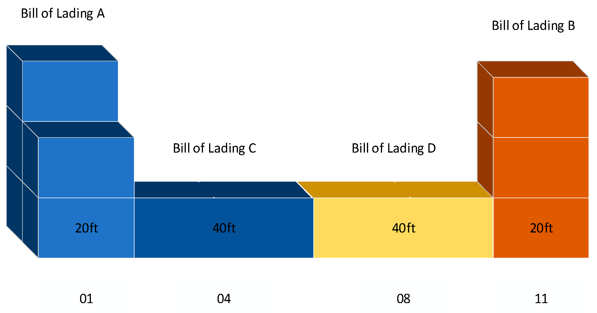
3.1. Problem Description

The container yard is a critical area within the port designated for storing containers, playing an essential role that encompasses tasks such as loading and unloading, transferring, storing, and the handing over of containers. The operational efficiency and effectiveness of this area are directly influenced by the joint planning between terminal operators and shipping companies. Effective management of the container yard is pivotal in elevating the port’s operational efficiency and enhancing its overall competitiveness. Specifically, by optimizing yard management, the dwell time of ships at the port can be reduced, thereby lowering operational costs and increasing vessel turnover rates. Additionally, higher throughput of containers and effective utilization of yard equipment not only improve operational efficiency but also make the port a more attractive logistics hub for more shipping companies and consigners. The typical layout of the container terminal yard is shown in Figure 1. The storage space of a container terminal yard is composed of several container zones, with container truck lanes between each zone. Additionally, each container zone may be equipped with 0–2-yard cranes for operations. Container unloading slots can be categorized as zone, row, stack, and level. Specific information about the placement of containers is determined by combining factors such as zone number, row number, stack (tier) number, and level number. Via corresponding coding rules, each container slot is assigned a unique identifier.
In practical production, the most significant difference between the intelligent unloading mode and the traditional unloading mode is that the intelligent unloading mode no longer requires the advance preparation of an unloading storage plan. When preparing the unloading storage plan, containers are grouped first, and then storage areas are allocated for each type of container. Common grouping rules can be summarized as follows: separate storage for empty and loaded containers, consideration of trans-shipment destinations, allocation based on container owner for empties, and separate storage for refrigerated, hazardous, and oversized containers. Although the intelligent unloading entry selection does not require the preparation of an unloading storage plan, the basic storage rules are the same as in the traditional unloading mode.
Intelligent unloading entry selection assigns a space in real-time for each unloading container. When the unloading container is placed on horizontal transport machinery, its storage slot in the yard is already determined, making the slot allocation more flexible. This flexibility is impossible to achieve using manual selection but is easily achievable via automated selection algorithms. Therefore, the core of intelligent unloading entry selection lies in the design of the space selection algorithm.
There are several limiting factors when choosing yard slots for unloading containers. The most crucial factors include ensuring that the selected yard slot is available, meaning it is not occupied by other containers, not reserved for other containers, or not designated as a reefer container plug; and ensuring that there are available yard cranes in the container zone where the selected yard slot is located, meaning there are yard cranes in the container zone, and they are not engaged in other tasks.
To maximize the efficiency of terminal operations and resource utilization, our berth selection algorithm specifically takes into account a variety of complex factors in dynamic operations. It has the capability to make real-time adjustments to unloading instructions, balancing the storage tasks in different container areas and the workload of yard cranes. This avoids issues such as yard congestion due to uneven crane workload or cranes idling while waiting for new tasks. This high level of dynamic responsiveness enables the algorithm to precisely adapt to the real-time requirements and changes in terminal unloading operations. By focusing on dynamic adjustments, the algorithm breaks through the limitations of static yard planning, significantly elevating the dynamism of berth selection decisions. This, in turn, further boosts the overall operational efficiency and competitiveness of the port.

3.2. Assumptions

In the context of constructing the model for container unloading entry selection, with the aim of arranging container zones and yard positions based on different levels of container groups, the following assumptions are made:
(1)
Containers entering and exiting the port yard are stored separately.
(2)
Due to the fact that special containers need to be stored in special container zones within the yard, and the majority of containers are standard containers, this study considers only standard containers and does not account for other container types.
(3)
The distribution of available capacity for yard slots during the planned period and the workload for each operational row in the yard are known.
(4)
During the loading and unloading operations, issues such as mechanical breakdowns are not considered, assuming that all process steps can function normally.
(5)
The yard does not pre-reserve flip slots for each operational row. When a particular row requires a flip slot, the slot is locked for that purpose.

3.3. Symbol Definitions

(1)
Model Dimensions
I : Representing all on-site containers in the yard, i , i I .
J : Representing the attraction methods of on-site containers in the yard to the target container, primarily including five attraction methods: longitudinal attraction, right-side attraction, left-side attraction, front-row attraction, and rear-row attraction.
K : Representing all waiting-to-be-allocated containers, k K .
L : Representing the bill of lading numbers of all waiting-to-be-allocated containers, l L .
N : Representing the owners of all waiting-to-be-allocated containers, n N .
(2)
Model parameters
a k : Representing the horizontal transport distance between the berth, on-site container i attracted in mode j , and the selected container zone and row for unloading container k .
s k : Representing the dimensions of unloading container k .
c o k : Representing the owner of unloading container k .
i e f k : 0–1 matrix indicating whether unloading container k is a heavy container. When unloading container k is heavy, the parameter is 1; when it is not, the parameter is 0.
i s i , k : 0–1 matrix indicating whether unloading container k has the same dimensions as on-site container i . When the two containers have the same dimensions, the parameter is 1; when they are different, the parameter is 0.
i s l k : 0–1 matrix indicating whether the dimensions of container k are 45 ft. When the dimensions of container k are 45 ft, the parameter is 1; when they are not, the parameter is 0.
i b l i , j , k : 0–1 matrix indicating whether the yard slot selected by on-site container i , attracted in mode j , for container k can accommodate a 45 ft container. When the yard slot selected by on-site container i , attracted in mode j j , for container k can accommodate a 45 ft container, the parameter is 1; when it cannot, the parameter is 0.
i f b i , j , k : 0–1 matrix indicating whether the yard slot selected by on-site container i , attracted in mode j , for unloading container k is the same as the yard slot in which on-site container i is located in its container zone. When the yard slot selected by on-site container i , attracted in mode j , for unloading container k is the same as the yard slot in which on-site container i is located in its container zone, the parameter is 1; when they are different, the parameter is 0.
i f r i , j , k : 0–1 matrix indicating whether the yard slot space selected by on-site container i , attracted in mode j , for unloading container k is in the same stack as the yard slot space where on-site container i is located in its container zone. When the yard slot space selected by on-site container i , attracted in mode j , for unloading container k is in the same stack as the yard slot location where on-site container i is located in its container zone, the parameter is 1; when they are in different stacks, the parameter is 0.
i a b i , j , k : When the dimensions of the container in the adjacent slot to the yard slot selected by on-site container i , attracted in mode j for unloading container k differ from the dimensions of the container in the yard slot selected by on-site container i , attracted in mode j , for unloading container k , the parameter is 1. When the adjacent slot to the yard slot selected by on-site container i , attracted in mode j , for unloading container k is empty, the parameter is 0. When the dimensions of the container in the adjacent slot to the yard slot selected by on-site container i , attracted in mode j , for unloading container k are the same as the dimensions of the container in the yard slot selected by on-site container i , attracted in mode j , for unloading container k , the parameter is −1.
i b g i : 0–1 matrix indicating whether the dimensions of the slot where on-site container i is located are 20 ft. When the dimensions of the slot where on-site container i is located are 20 ft, the parameter is 1; when they are not, the parameter is 0.
l c k : Represents the bill of lading number for unloading container k .
i l c i , k : 0–1 matrix indicating whether the bill of lading number of unloading container k is the same as that of on-site container i . When the bill of lading number of unloading container k is the same as that of on-site container i , the parameter is 1; when they are different, the parameter is 0.
i o c i , k : 0–1 matrix indicating whether the owner of unloading container k is the same as the owner of on-site container i . When the owner of unloading container k is the same as the owner of on-site container i , the parameter is 1; when they are different, the parameter is 0.
t i : Represents the number of tiers or stack levels of on-site container i .
m t i : Represents the maximum allowable stack height for on-site container i ’s stack or stack tier.
i b t i , j , k , l : 0–1 matrix indicating whether the yard slot selected by on-site container i , attracted in mode j , for unloading container k , is storing a container from bill of lading l . When the yard slot selected by on-site container i , attracted in mode j , for unloading container k is storing a container from bill of lading l , the parameter is 1; when it is not, the parameter is 0.
i b o i , j , k , n : 0–1 matrix indicating whether the yard slot selected by on-site container i , attracted in mode j , for unloading container k , is storing a container from owner n . When the yard slot selected by on-site container i , attracted in mode j , for unloading container k is storing a container from owner n , the parameter is 1; when it is not, the parameter is 0.
i n b j : 0–1 matrix indicating whether the j attraction mode is a between-bay attraction mode (front-bay attraction mode or rear-bay attraction mode). When the j attraction mode is a between-bay attraction mode (front-bay attraction mode or rear-bay attraction mode), the parameter is 1; when it is not, the parameter is 0.
i y c i , j , k , n : 0–1 matrix indicating whether the yard area selected by on-site container i , attracted in mode j , for unloading container k , has yard crane (gantry crane) n . When there is a yard crane (gantry crane) n , the parameter is 0; when there is no yard crane (gantry crane), the parameter is 1.
w y c i , j , k , n : 0–1 matrix indicating whether the yard area selected by on-site container i , attracted in mode j , for unloading container k , has yard crane n in operation. When there is a yard crane in operation at the yard area, the parameter is 1; when there is no yard crane in operation at the yard area, the parameter is 0.
i n i , j , k : 0–1 matrix indicating whether the yard slot selected by on-site container i , attracted in mode j , for unloading container k is empty. When the yard slot is empty, the parameter is 1; when it is not empty, the parameter is 0.
i l i , j , k : 0–1 matrix indicating whether the yard slot selected by on-site container i , attracted in mode j , for unloading container k is locked. When the yard slot is locked, the parameter is 0; when it is not locked, the parameter is 1. When a yard slot in a bay needs to reserve a flip slot, the slot is locked.
i l b i , j , k : 0–1 matrix indicating whether the bay where the yard slot selected by on-site container i , attracted in mode j , for unloading container k is located is locked. When the bay is locked, the parameter is 0; when it is not locked, the parameter is 1.
d i , j , k : Represents the distance from the yard slot selected by on-site container i , attracted in mode j , for unloading container k to the outer roadway.
(3)
Decision variables
X i , j , k : 0–1 matrix, where X i , j , k = 1 indicates that on-site container i attracts container k in mode j , and X i , j , k = 0 indicates that on-site container i does not attract container k in mode j .

3.4. Model Construction
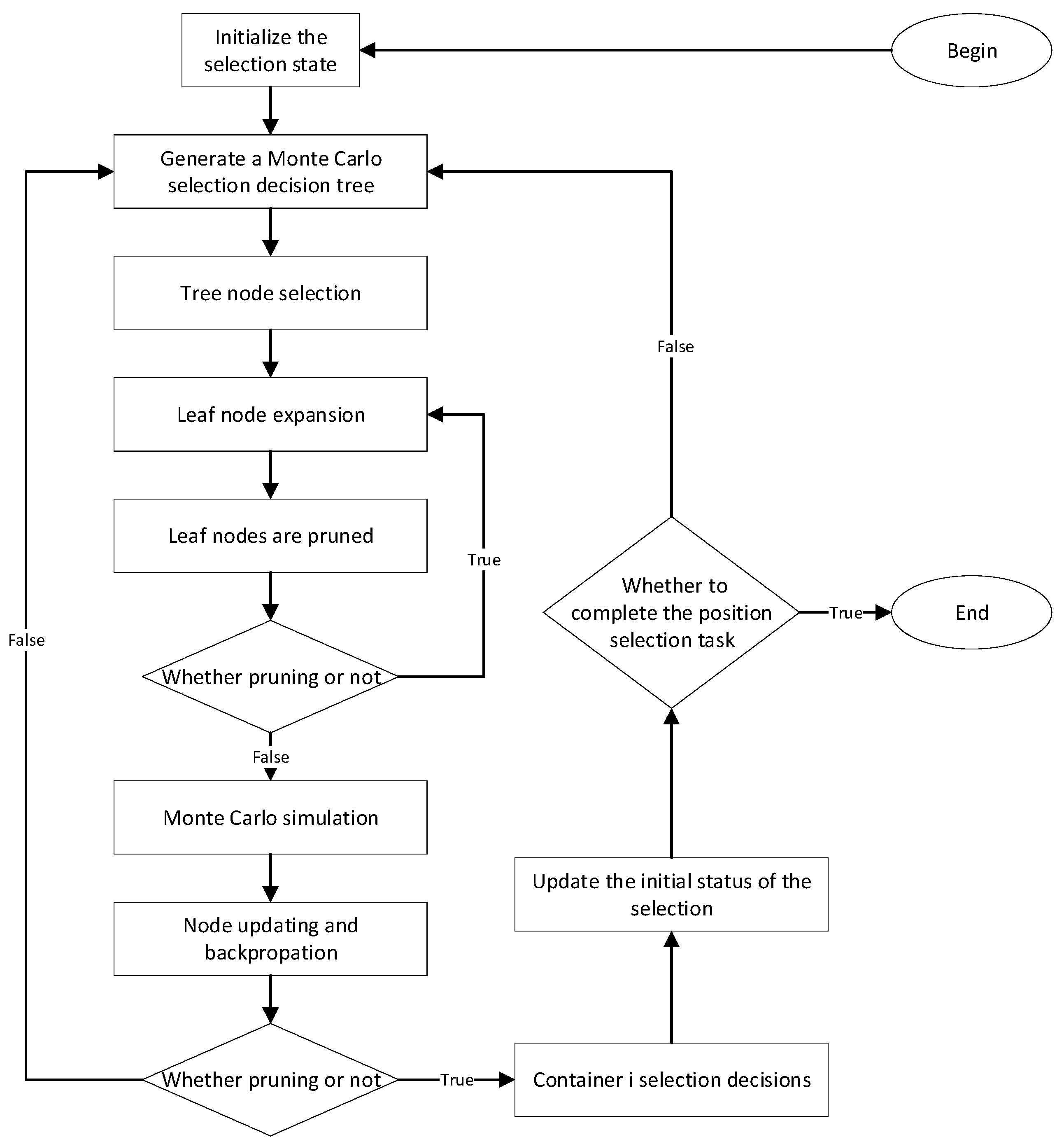
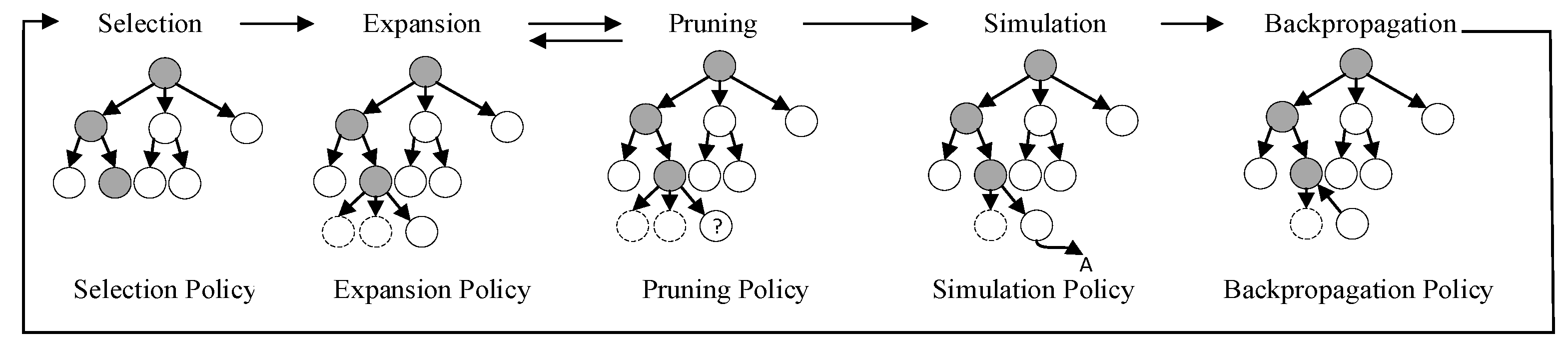
The total objective function is to maximize the attractiveness of the container yard slots for unloading containers. Therefore, K = 1 . γ represents the coefficients or weights assigned to different sub-objectives when selecting the unloading positions. These weights are used to balance the relative importance of each sub-objective in the optimization problem. The model for selecting the unloading container’s entry position in the yard is as follows:
F = m a x γ 1 F 1 + γ 2 F 4 + γ 3 F 5 + γ 4 F 6 γ 5 F 7
The objective function (1) maximizes the attractiveness of yard slots in the unloading position selection, with different importance levels for each sub-objective. Here, γ 1 , γ 2 , γ 3 , γ 4 , γ 5 represent weights, and γ 1 + γ 2 + γ 3 + γ 4 + γ 5 = 1 . These weights enable researchers to explicitly specify the relative priorities and importance of each sub-objective during the optimization process, thereby influencing the final optimization outcome.
F 1 = m a x i I j J k K i l c i , k · i f b i , j , k · i e f k X i , j , k i I j J k K I F B i , j , k + X i , j , k + i I j J k K i o c i , k · i f b i , j , k · ( 1 i e f k ) X i , j , k i I j J k K i f b i , j , k + X i , j , k × 100 %
Sub-objective function (2) indicates that when the unloading container is a heavy container, the better the selection results when there are more containers in the same container zone bay that belong to the same bill of lading as the unloading container; when the unloading container is an empty container, the better the selection results when there are more containers in the same container zone bay that belong to the same owner as the unloading container.
F 2 = m i n i I j J k K l L i b t i , j , k , l · i e f k · X i , j , k + i I j J k K n N i b o i , j , k , n · ( 1 i e f k ) · X i , j , k
Sub-objective function (3) represents that when the unloading container is heavy, the higher the purity within the same container zone bay (fewer bills of lading), the better the selection results. Similarly, when the unloading container is empty, the higher the purity within the same container zone bay (fewer owners), the better the selection results. This aims to achieve the separation of large-ticket containers and miscellaneous-ticket containers.
F 1 = m a x α 1 F 1 + α 2 1 F 2
Sub-objective function (4) aims to maximize the purity of container zone bays. It considers F 1 [ 0,1 ] and F 2 [ 1 , + ] , where α 1 and α 2 represent weights, and α 1 + α 2 = 1 .
F 1 = m a x β 1 F 1 + β 2 F 3
Sub-objective function (5) aims to maximize the purity of stack tiers. When the unloading container is heavy, the more containers in the same stack tier that belong to the same bill of lading, the better the selection results. Similarly, when the unloading container is empty, the more containers in the same stack tier that belong to the same owner, the better the selection results, aiming to reduce the need for flipping containers.
F 1 = m a x β 1 F 1 + β 2 F 3
Sub-objective function (6) aims to maximize overall purity, which includes both container zone bay purity and stack tier purity. β 1 and β 2 represent weights, and β 1 + β 2 = 1 .
F 4 = m a x i I j J k K 2 i y c i , j , k w y c i , j , k X i , j , k
Sub-objective function (7) aims to maximize the attractiveness of yard slots based on the availability of yard equipment (gantry cranes) and ongoing yard operations.
F 5 = m a x i I j J k K i n b j · i a b i , j , k · X i , j , k
Sub-objective function (8) aims to maximize the attractiveness of yard slots by promoting cross-distribution of different-sized containers when selecting new slots.
F 6 = m a x i I j J k K d i , j , k · X i , j , k
Sub-objective function (9) considers safety by minimizing the potential for yard crane operations that involve crossing containers, aiming to select slots farther from the outer roadway.
F 7 = m i n i I j J k K a k · X i , j , k
Sub-objective function (10) minimizes horizontal transport distances, prioritizing slots closer to the berth when multiple yard slots are available for selection.
i I j J X i , j , k = 1
Constraint (11) ensures that each unloading container will always be placed in the yard by attracting it to a specific slot by a certain on-site container in a specific manner.
i I j J k K X i , j , k = 1
Constraint (12) indicates that an unloading container will always be attracted to a yard slot by a certain on-site container in a specific manner.
i I j J k K i n i , j , k · i l i , j , k · X i , j , k = 1
Constraint (13) is the slot availability constraint. When unloading containers need to be stacked in the yard, it is necessary to check if the yard slot is available. This mainly involves checking whether the yard slot is empty, meaning there are no other containers already stacked in that slot, and whether the slot is locked by other containers or tasks. Locking means that other tasks are scheduled to operate in that slot, making it unavailable for further operations. If the slot is empty but locked by other containers, it cannot be used for stacking.
i I j J t i + i y j X i , j , k     m t i
Constraint (14) is the stack tier height constraint, indicating that the height of a stack tier should not exceed the specified stack tier height. Different terminals may have different stack tier height requirements, typically around four tiers. When a row in the yard has reached the maximum allowable stack tier height, no more containers can be stacked above it.
i I j J k K i s i , k · X i , j , k = 1
Constraint (15) is the container size constraint, stating that containers in the same bay should be the same size. Different-sized containers should not be stacked in the same bay.
i I j J k K i f b i , j , k · i l b i , j , k · i n b j · X i , j , k = 1
Constraint (16) is the new bay availability constraint. When a new bay is needed, the selected bay must be available. A bay must satisfy the condition that it does not have other containers stacked in it, and it has not been locked by other tasks.
i I j J k K i s l k · i b l i , j , k · X i , j , k = 1
Constraint (17) specifies that 45 ft containers can only be placed in bays that allow the stacking of 45 ft containers. Typically, 45 ft containers are stacked at the two ends of the container yard in two large bays.

4. Algorithm Design

The problem studied in this paper, which is the intelligent unloading position selection for unloading containers, is a decision problem with multiple choices and requires satisfying multiple objectives and constraints. As the number of unloading containers increases, solving the problem becomes exponentially more challenging. Using commercial softwares like CPLEX 12.10 may not provide a solution within a reasonable time frame for real-world port requirements. Therefore, this paper proposes the use of the Monte Carlo tree search (MCTS) algorithm to obtain an approximate optimal solution to the problem. The algorithm process is illustrated in Figure 2.
The Monte Carlo tree search (MCTS) algorithm designed in this paper for unloading position selection during unloading operations involves five main steps in each iteration: Selection Policy, Expansion Policy, Simulation Policy, Backpropagation Policy, and the newly added Pruning Policy. The specific framework of the MCTS algorithm for unloading position selection is depicted in Figure 3. The pruning step is introduced to quickly reduce the solution space and improve the efficiency of the algorithm. By embedding the objective functions and constraints of the unloading position selection model into the Monte Carlo tree search algorithm, the goal is to ultimately solve the problem of selecting unloading positions for unloading containers.

4.1. Selection Policy

The selection of tree nodes occurs after updating node information, and it is based on the magnitude of node evaluation values. It proceeds from the root node downward until it reaches a leaf node. Different selection policies utilize various methods for calculating tree node evaluation values. Commonly used selection evaluation methods include the UCT algorithm, AMAF algorithm, and RAVE algorithm.
(1)
UCT algorithm
U C T i = X i ¯ + 2 C 2 ln ( N ) N i
N represents the number of times the current node has been visited, N i represents the number of times the child nodes have been visited, and X ¯ i represents the estimated utility value of the child nodes after multiple visits. C is a positive constant used to balance the trade-off between exploration and exploitation in the algorithm’s search process.
(2)
AMAF algorithm
A M A F i = ( Q i + Q i ) N i + N i + 2 C 2 ln ( N + N ) N i + N i
N i represents the actual number of times node i has been visited, Q i represents the actual return value of node i , N i and Q i represent the number of times and return value obtained for node i using the AMAF strategy, N represents the number of times the parent node i has been visited, and N represents the increase in the number of visits.
(3)
RAVE algorithm
R E V E r = α A M A F r + ( 1 α ) U C T i
The RAVE algorithm combines the characteristics of the UCT and AMAF algorithms, improving both convergence speed and solution quality via weighted methods. The process of determining the value of α is dynamic and optimized using the RAVE strategy. The algorithm uses AMAF to determine the generation direction of the search tree and then fine-tunes the precise search direction using UCT. In the RAVE algorithm, the value of α decreases as the number of visits increases.
α = m a x 0 ,   M m ( N ) M
This article uses the REVE algorithm as the selection strategy. Starting from the root node, it always selects the child node with the highest REVE value until it reaches a leaf node. This policy is used in the unloading space selection algorithm until the unloading container is placed in the optimal space.

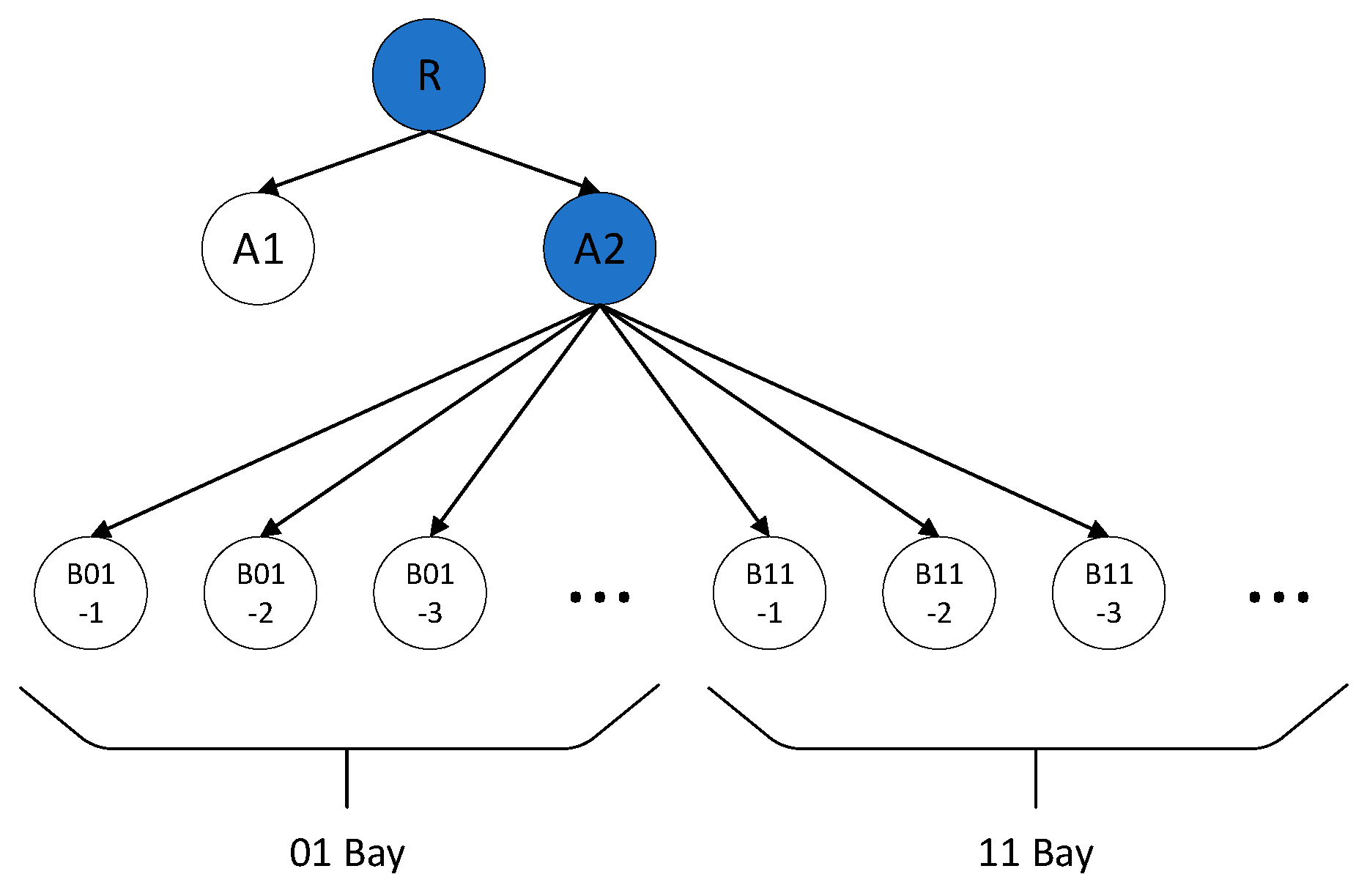
4.2. Expansion Policy
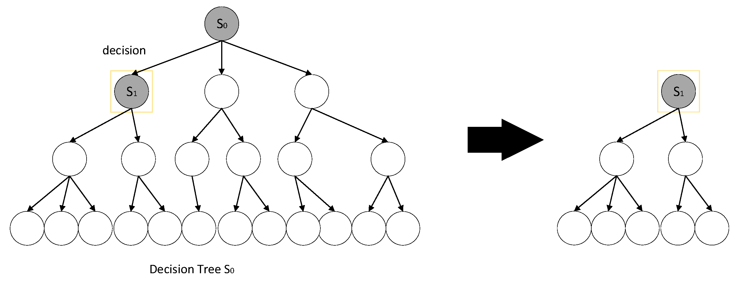
The expansion policy is applied during the expansion phase of the tree search. Node expansion refers to the situation where the current state is at a leaf node, but the space selection task is not yet complete, so the current node is expanded in a meaningful way. During expansion, all possible space selections for the next unloading container space must be identified. At this stage, the expanded space selections must satisfy all the constraints of the unloading space selection model. An example is shown in Figure 4, where several bay positions are considered.
Assuming the current unloading container is a 20 ft container from Bill of Lading B, the available space selections are bays 01, 04, 08, and 11 in a particular block area. Due to size constraints during stacking, the container cannot be placed in bays 04 and 0. Therefore, during expansion, only bays 01 and 1 are considered. The expanded search tree at this stage is shown in Figure 5.

4.3. Pruning Policy

Pruning is a crucial step in the context of the unloading entry selection problem, primarily considering whether it satisfies the unloading container entry selection model. Continuing with the example of the unloading container from the previous section, suppose the current unloading container belongs to Bill of Lading B. To maximize Equation (6), the space in Bay 01 is eliminated from the expanded results. The pruned search tree after this step is shown in Figure 6.

4.4. Simulation Policy

Monte Carlo simulation is based on the expanded child nodes, and it randomly simulates the entire selection process until the selection task is completed. The simulation process for unloading entry selection is illustrated in Figure 7.
The simulation policy adopted in this article is based on the objective function in the model for selecting the destination of unloading containers discharged from ships. The greater the R i value, the better the attraction of container i for the currently waiting container, and the higher the probability of container i being selected. In this article, a roulette wheel selection method is used to choose each expanded leaf node in the search tree, calculate the probability of each expanded leaf node being selected, and compare to select the container with the maximum P i value. The probability of a container being selected is calculated as follows:
p i = R i i I R i

4.5. Backtracking Policy

Backpropagation policies commonly include UCT policy, AMAF policy, and REVE policy. REVE combines UCT and AMAF but follows the same backpropagation approach as AMAF, as shown in Figure 8. If node A3 also meets the conditions, the information of nodes A2, R, and A3 will be updated at this point. This paper adopts the AMAF and REVE policy backtracking method to facilitate the search for a more satisfactory solution.

4.6. Nested Tree Policy

After completing an unloading approach location task, it is necessary to recreate the search tree and give an initial state. However, if the current search tree and node information can be retained after completing an unloading approach location task, this greatly reduces the computational load of the algorithm and improves the solution speed of the algorithm, as shown in Figure 9. This method of preserving the search tree is called Nested Monte Carlo Search (NMCS).

5. Experiments

5.1. Experimental Platform

The algorithm program for solving the unloading site selection problem in this paper was developed using the Python programming language. The experimental environment includes a Windows 10 64-bit operating system, an Intel Core i7-8550U processor, 8 GB of RAM, and a quad-core 2.00 GHz CPU.

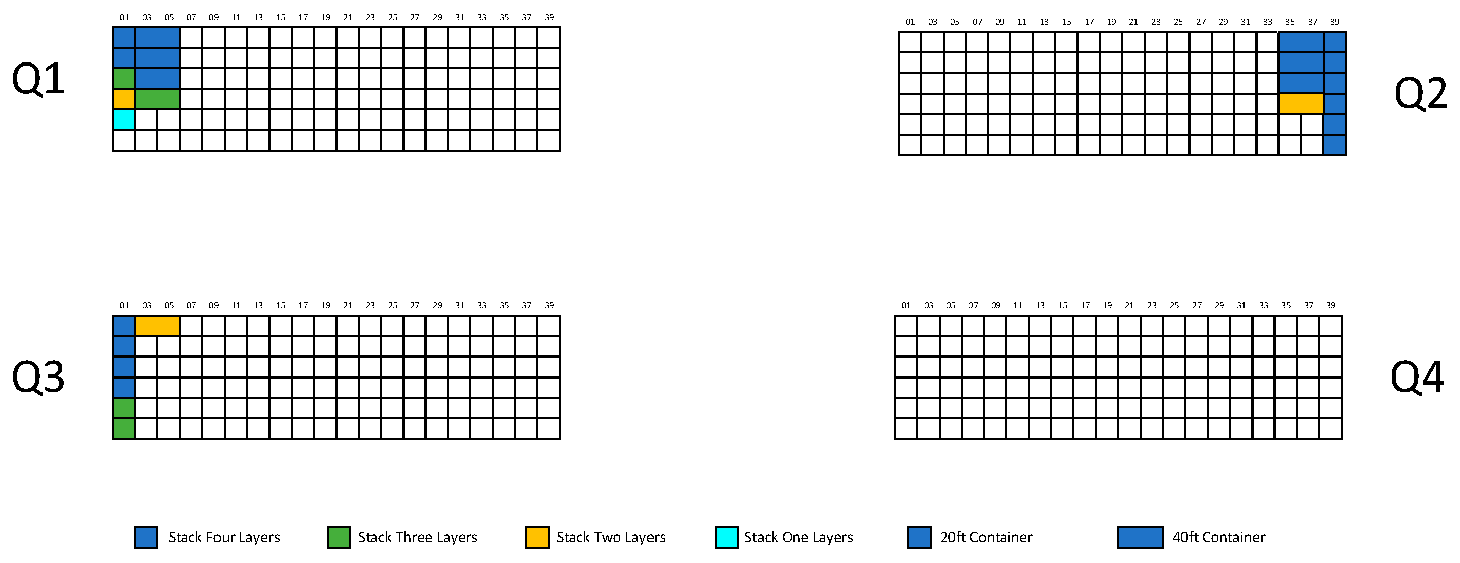
5.2. Experimental Data

Based on the Monte Carlo tree search algorithm designed in Chapter 4 for the unloading site selection problem (REVE-MCTS algorithm), it was applied to select unloading sites for 182 containers, with a total of 1920 available yard slots. Due to the large size of the solution space, the algorithm was set to run for 10,000 iterations. In Monte Carlo tree search algorithms, more iterations generally lead to better solutions.
Since the REVE policy was used as the selection policy in the Monte Carlo tree search algorithm designed in this paper, the value of C was set to 1/√2 to ensure algorithm effectiveness. The impact factors were determined based on expert ratings, as shown in Table 1.
This paper uses actual data from a portion of the containers at a container terminal in Ningbo Port as case study data. The data include information on the current storage status in the container yard for containers, as shown in Figure 10. There are four container yards labeled as Q1, Q2, Q3, and Q4. Each yard has 20 bays, each bay has 6 rows (strings), and each row can stack up to 4 layers. Therefore, there are a total of 1920 slots available for 20 ft containers. However, considering the need to reserve slots for container flips, the actual number of slots available for selection by the containers may be less than 1920.
Table 2 describes the information of the imported containers of a container ship to be unloaded.

5.3. Calculation of Experimental Results

The Monte Carlo tree search algorithm for solving the unloading container space selection problem was utilized to obtain space selection results for some of the unloading containers. The results for a portion of the unloading containers are shown in Table 3.
The selection results of 182 unloading containers are shown in Figure 11. In Figure 11, each letter or color represents a bill of lading number for unloaded heavy containers, and each letter or color represents a container owner for unloaded empty containers, providing a more intuitive display of the location selection results.

5.3.1. Comparative Analysis of Manual Allocation Solution Results

The manual yard plan was used to select the unloading position, and the final selection results of some containers to be unloaded are shown in Table 4.
Comparing the results of manual selection and intelligent selection, it is evident that intelligent selection concentrates more on large-ticket containers while distributing small-ticket containers. This better adheres to the “centralized and dispersed” selection rule. Additionally, intelligent selection improves unloading selection efficiency and enhances container yard space utilization.

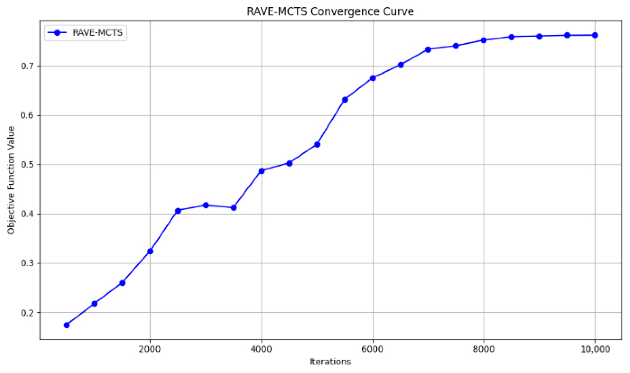
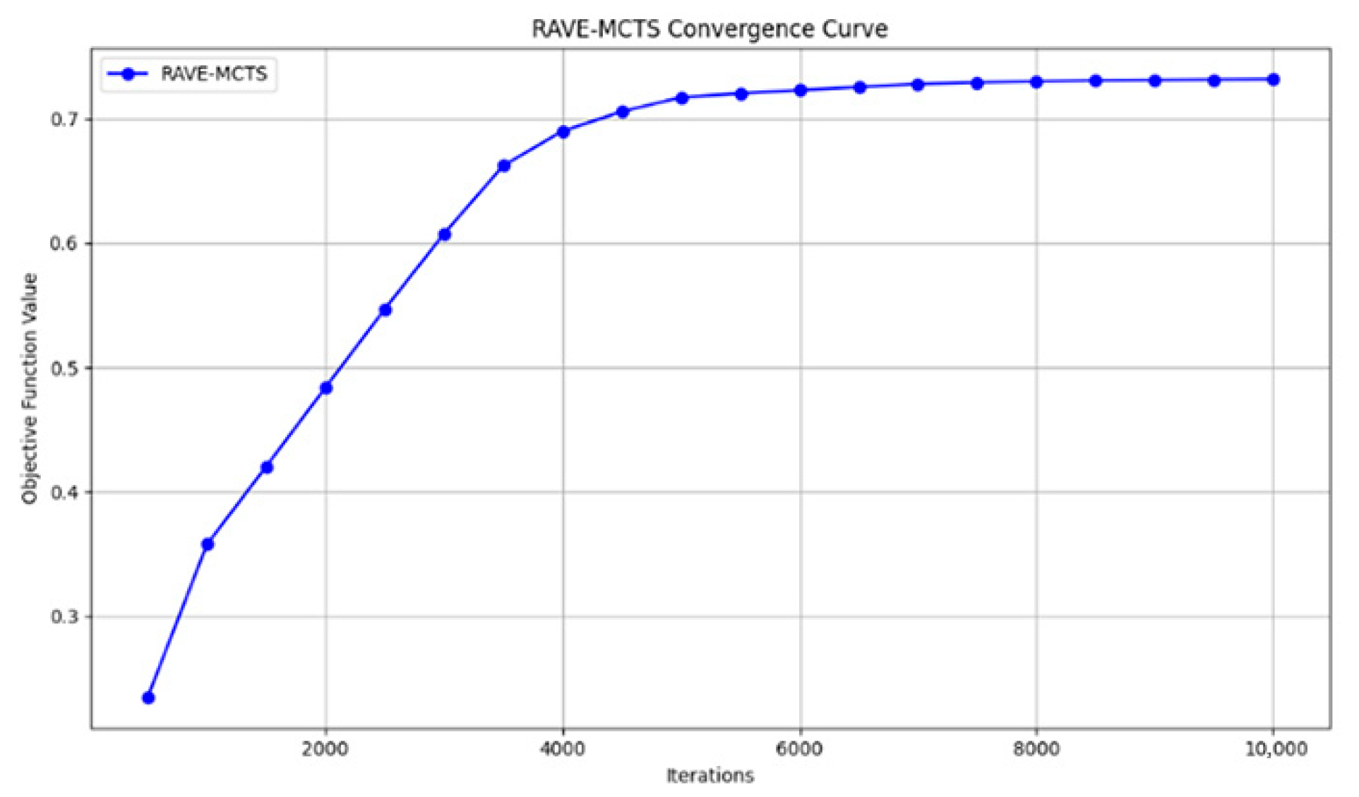
5.3.2. Algorithm Convergence Analysis

To further validate the effectiveness of the algorithm, let us take one of the containers, CARU2728930, as an example. The final selected space is Q10161. The convergence curve of the algorithm is shown in Figure 12. Due to the large solution space, the simulation process is very complex, leading to slow convergence. The objective function tends to flatten out around 8500 iterations. It is evident that the longer the Monte Carlo tree search algorithm runs, the better the solution quality.
Via the analysis of the selection results, it was found that all the containers were finally stacked in Q1 and Q2 areas. To verify the applicability of the container unloading space selection algorithm, we now reduce the number of available import container storage areas from four to two, removing Q3 and Q4 areas. All other conditions remain the same. We continue to use the container CARU2728930 as an example, with the final selected space being Q10161. The convergence curve of the algorithm in this scenario is shown in Figure 13. It is observed that the objective function tends to flatten out around 4000 iterations. This demonstrates that the size of the solution space has a significant impact on the algorithm’s performance, and a smaller solution space tends to yield satisfactory solutions.
To further understand the impact of the number of iterations on the container unloading space selection algorithm, the number of iterations is set to 5000. All other conditions remain the same. Using the container CARU2728930 as an example, the final selected space is Q10134, stacked on top of the existing containers in the yard. The convergence curve of the algorithm in this scenario is shown in Figure 14. It can be observed that the objective function did not converge. This highlights the importance of the number of iterations in the algorithm’s solution process.
In this paper, the REVE-MCTS algorithm is adopted, and in order to verify the superiority of the algorithm, the algorithm is compared with the UCT-MCTS and AMAF-MCTS algorithms. At the same time, considering the influence of the number of iterations on the algorithm, the results are shown in Table 5.
According to Table 5, the corresponding convergence curves are shown in Figure 15. One common characteristic of all three algorithms is that the convergence improves as the number of iterations increases. However, with more iterations, the REVE-MCTS algorithm clearly outperforms the UCT-MCTS algorithm and the AMAF-MCTS algorithm. The REVE-MCTS algorithm is better at searching for more satisfactory solutions.

5.3.3. Algorithm Effectiveness Analysis

To validate the effectiveness of the unloading container positioning algorithm and assess the feasibility of its decision making in solving real operational problems, the traditional dockyard operations personnel were asked to arrange positions for 182 unloading containers based on their operational experience. They used the traditional planning and positioning policy. Under the same conditions, the comparison results of the positioning objective function for unloading containers and the results of manual planning positioning are shown in Figure 16. Using the intelligent algorithm to solve the unloading container positioning problem results in better overall performance compared to the manual planning and scheduling method.
The solving times are shown in Table 6. Using the intelligent algorithm to solve the unloading container positioning problem can reduce the solving time and improve operational efficiency. The unloading container intelligent positioning algorithm is not only capable of reducing the workload of yard planning personnel but also has practical significance for the intelligent management of the dockyard.

5.3.4. Algorithm Robustness Analysis

Robustness, also known as insensitivity or stability, primarily represents the degree to which an algorithm depends on its parameters. A smaller value of robustness indicates better robustness, demonstrating that the algorithm is less sensitive to parameter changes and that the parameter has a weaker impact on the algorithm’s performance.
E f = C b e s t C a v g C b e s t × 100 %
In Equation (23), E f represents the robustness performance metric, C b e s t represents the algorithm’s best solution, and C a v g represents the average solution. For the unloading space selection problem, a calculation based on Equation (23) yields a value of 4.82%. This demonstrates that the algorithm has good robustness performance and is not highly dependent on its parameters.

6. Conclusions

The production activities at container terminals primarily encompass four critical stages: loading, unloading, cargo assembly, and container retrieval. In the unloading phase, the allocation of storage space for unloaded containers in the yard serves a pivotal bridging role. It not only impacts the berthing time of the container ships but also has implications for subsequent container retrieval operations. The primary focus of this paper is to address the problem of allocating storage space for unloaded containers. This study is targeted at traditional container terminal loading and unloading workflows. It aims to automate the process of allocating yard positions for unloaded containers via computer systems, eliminating the need for manual planning. The system dynamically assigns yard positions by comprehensively considering factors such as equipment availability, task distribution, and current stacking conditions. This paper establishes an unloading space selection model based on the actual stacking rules and corresponding constraints at the container terminal, with the objective of maximizing space attractiveness. The proposed approach builds upon the Monte Carlo tree search (MCTS) algorithm and introduces improvements, including pruning during the four main stages of each iteration (selection, expansion, simulation, and backpropagation) to enhance algorithm convergence speed. It also incorporates a nested tree policy after completing each task to reduce computational requirements and enhance overall algorithm performance. This customized Monte Carlo tree search algorithm is designed to address unloading space selection problems effectively.
The numerical experiment results show that the proposed algorithm can basically surpass the level of manual planning in comprehensive performance under different scale cases, and its performance is more prominent in large-scale cases. The longer the algorithm calculation time and the more iterations, the better the location selection effect. In the numerical experiment, the algorithm obtained the solution in an average of 528 s, which was about 54% faster than the manual planning time of 1167 s. The REVE-MCTS algorithm selected in the numerical experiment was significantly better than the other two algorithms in large-scale cases and had good robustness. In addition to optimizing the space utilization of the yard, it also showed excellent convergence performance in iterative testing compared to other algorithms such as UCT-MCTS and AMAF-MCTS. The robustness index of the algorithm was 4.82%, showing high stability and low parameter dependence.
The algorithm proposed in this paper fulfills multiple requirements for the storage space allocation of unloaded containers. First, it deviates from the traditional labor-intensive approach of manual planning, thereby freeing up labor resources. Second, it ensures that unloaded containers are efficiently moved from the ship and strategically placed within the yard, achieving dynamic space allocation to enhance efficiency. Third, the algorithm facilitates the automatic stacking of bulk containers, reducing the rate of container flipping in subsequent pick-up operations. The application of this algorithm holds significant promise for improving operational efficiency in container terminal unloading processes.
In future research, it may be worthwhile to explore the use of historical data to uncover potential objective patterns, such as predicting unloading container stacking times. This could provide a more reliable basis for unloading space assignment decisions and optimize yard management.

Author Contributions

Conceptualization, X.W. and N.Z.; methodology, X.W. and N.Z.; software, C.M.; validation, X.W. and N.Z.; formal analysis, X.W. and N.Z.; investigation, X.W., N.Z. and C.M.; resources, X.W. and C.M.; data curation, X.W. and N.Z.; writing—original draft preparation, X.W.; writing—review and editing, X.W. and C.M.; visualization, N.Z.; supervision, X.W., N.Z. and C.M.; project administration, X.W., N.Z. and C.M. All authors have read and agreed to the published version of the manuscript.

Funding

This research was supported by the Science and Technology Commission of Shanghai Municipality (No. 22ZR1427700 and No. 23692106900).

Institutional Review Board Statement

Not applicable.

Informed Consent Statement

Not applicable.

Data Availability Statement

The data used in this study did not involve any public data sets.

Conflicts of Interest

The authors declare no conflict of interest.

References

  1. Stahlbock, R.; Voß, S. Operations research at container terminals: A literature update. OR Spectr. 2008, 30, 1–52. [Google Scholar] [CrossRef]
  2. Wen, W.; Fan, H.; Zhang, W.; Ma, M.; Li, Y. Simulating the growth of container ship size and port city economy development. In Proceedings of the 2015 IEEE International Conference on Information and Automation, Lijiang, China, 8–10 August 2015; pp. 2574–2579. [Google Scholar] [CrossRef]
  3. Dulebenets, M.A. Application of evolutionary computation for berth scheduling at marine container terminals: Parameter tuning versus parameter control. IEEE Trans. Intelligent. Transp. Syst. 2017, 19, 25–37. [Google Scholar] [CrossRef]
  4. Jin, J.G.; Lee, D.H.; Cao, J.X. Storage Yard Management in Maritime Container Terminals. Transp. Sci. 2016, 50, 1300–1313. [Google Scholar] [CrossRef]
  5. Mi, C.; Liu, Y.; Zhang, Y.; Wang, J.; Feng, Y.; Zhang, Z. A Vision-based Displacement Measurement System for Foundation Pit. IEEE Trans. Instrum. Meas. 2023, 72, 2525715. [Google Scholar] [CrossRef]
  6. Mi, C.; Huang, S.; Zhang, Y.; Zhang, Z.; Postolache, O. Design and Implementation of 3-D Measurement Method for Container Handling Target. J. Mar. Sci. Eng. 2022, 10, 1961. [Google Scholar] [CrossRef]
  7. Zhang, Y.; Huang, Y.; Zhang, Z.; Postolache, O.; Mi, C. A vision-based container position measuring system for ARMG. Meas. Control 2023, 56, 596–605. [Google Scholar] [CrossRef]
  8. Yu, H.; Deng, Y.; Zhang, L.; Xiao, X.; Tan, C. Yard Operations and Management in Automated Container Terminals: A Review. Sustainability 2022, 14, 3419. [Google Scholar] [CrossRef]
  9. Kizilay, D.; Eliiyi, D.T. A comprehensive review of quay crane scheduling, yard operations and integrations thereof in container terminals. Flex. Serv. Manuf. J. 2021, 33, 1–42. [Google Scholar] [CrossRef]
  10. Zhang, C.; Guan, H.; Yuan, Y.; Chen, W.; Wu, T. Machine learning-driven algorithms for the container relocation problem. Transp. Res. Part B 2020, 139, 102–131. [Google Scholar] [CrossRef]
  11. Yu, H.; Huang, M.; Zhang, L.; Tan, C. Yard template generation for automated container terminal based on bay sharing strategy. Ann. Oper. Res. 2022. [Google Scholar] [CrossRef]
  12. Fan, H.; Peng, W.; Ma, M.; Yue, L. Storage Space Allocation and Twin Automated Stacking Cranes Scheduling in Automated Container Terminals. IEEE Trans. Intell. Transp. Syst. 2022, 23, 14336–14348. [Google Scholar] [CrossRef]
  13. Ambrosino, D.; Xie, H. Optimization approaches for defining storage strategies in maritime container terminals. Soft Comput. 2023, 27, 4125–4137. [Google Scholar] [CrossRef]
  14. Niu, B.; Xie, T.; Tan, L.; Bi, Y.; Wang, Z. Swarm intelligence algorithms for Yard Truck Scheduling and Storage Allocation Problems. Neurocomputing 2016, 188, 284–293. [Google Scholar] [CrossRef]
  15. Bruns, F.; Knust, S.; Shakhlevich, N.V. Complexity results for storage loading problems with stacking constraints. Eur. J. Oper. Res. 2016, 249, 1074–1081. [Google Scholar] [CrossRef]
  16. Petering, M.E.H.; Hussein, M.I. A new mixed integer program and extended look-ahead heuristic algorithm for the block relocation problem. Eur. J. Oper. Res. 2013, 231, 120–130. [Google Scholar] [CrossRef]
  17. Yu, M.; Liang, Z.; Teng, Y.; Zhang, Z.; Cong, X. The inbound container space allocation in the automated container terminals. Expert Syst. Appl. 2021, 179, 115014. [Google Scholar] [CrossRef]
  18. Zhen, L.; Zhuge, D.; Wang, S.; Wang, K. Integrated berth and yard space allocation under uncertainty. Transp. Res. Part B 2022, 162, 1–27. [Google Scholar] [CrossRef]
  19. Liu, C.; Zhang, C.; Zheng, L. A bi-objective model for robust yard allocation scheduling for outbound containers. Eng. Optim. 2016, 49, 113–135. [Google Scholar] [CrossRef]
  20. Luo, J.; Wu, Y.; Mendes, A.B. Modelling of integrated vehicle scheduling and container storage problems in unloading process at an automated container terminal. Comput. Ind. Eng. 2016, 94, 32–44. [Google Scholar] [CrossRef]
  21. Wu, K.; Ting, C. A beam search algorithm for minimizing reshuffle operations at container yards. In Proceedings of the International Conference on Logistics and Maritime Systems, Busan, Republic of Korea, 15–17 September 2010. [Google Scholar] [CrossRef]
  22. Hu, W.; Wang, H.; Min, Z. A storage allocation algorithm for outbound containers based on the outer-inner cellular automaton. Inf. Sci. 2014, 281, 147–171. [Google Scholar] [CrossRef]
  23. Galle, V.; Barnhart, C.; Jaillet, P. Yard crane scheduling for container storage, retrieval, and relocation. Eur. J. Oper. Res. 2018, 271, 288–316. [Google Scholar] [CrossRef]
  24. Wang, K.; Zhen, L.; Wang, S.; Laporte, G. Column generation for the integrated berth allocation, quay crane assignment, and yard assignment problem. Transp. Sci. 2018, 52, 812–834. [Google Scholar] [CrossRef]
  25. Rimmel, A.; Teytaud, F.; Teytaud, O. Biasing Monte-Carlo simulations through RAVE values. In International Conference on Computers and Games; Lecture Notes in Computer Science (Including Subseries Lecture Notes in Artificial Intelligence and Lecture Notes in Bioinformatics); Springer: Berlin/Heidelberg, Germany, 2011; Volume 6515, pp. 59–68. [Google Scholar] [CrossRef]
Figure 1. Simplified layout of container terminal.
Jmse 11 02109 g001
Figure 2. Flow chart of Monte Carlo tree search algorithm for unloading positioning.
Jmse 11 02109 g002
Figure 3. Monte Carlo tree search algorithm framework for unloading entry selection.
Jmse 11 02109 g003
Figure 4. Expansion policy case for container space selection.
Jmse 11 02109 g004
Figure 5. Expansion policy.
Jmse 11 02109 g005
Figure 6. Pruning policy.
Jmse 11 02109 g006
Figure 7. Simulation process of unloading positioning.
Jmse 11 02109 g007
Figure 8. AMAF and REVE backtracking policies.
Jmse 11 02109 g008
Figure 9. Nested tree policy.
Jmse 11 02109 g009
Figure 10. Storage status in the block.
Jmse 11 02109 g010
Figure 11. Position selection results of small-scale studies.
Jmse 11 02109 g011
Figure 12. Convergence curve.
Jmse 11 02109 g012
Figure 13. Improved convergence curve.
Jmse 11 02109 g013
Figure 14. Convergence after modifying the number of iterations.
Jmse 11 02109 g014
Figure 15. Comparison of convergence of the three algorithms.
Jmse 11 02109 g015
Figure 16. Comparison of the values of each objective function under the two schemes.
Jmse 11 02109 g016
Table 1. Numerical values of impact factors.
Parameter α 1 α 2 β 1 β 2 γ 1 γ 2 γ 3 γ 4 γ 5
Value0.40.60.40.60.20.20.20.20.2
Table 2. Information on containers to be unloaded.
Container NumberContainers SizeContainers TypeContainers StatusBill of LadingUnloading
Sequence
CARU272893020GPloaded A1
GLDU374961020GPloadedA2
MEDU145368420GPloadedA3
GATU057997220GPloadedA4
FBLU202556720GPloadedD5
INKU656967640GPloadedD6
MEDU177054420GPloadedD7
MEDU178236020GPloadedF8
CLHU376369320GPloadedF9
GATU112657020GPloadedE10
GLDU524664120GPloadedE11
MEDU170550720GPloadedE12
CATU291282020GPloadedC13
CRXU116360720GPloadedC14
GATU071461920GPloadedC15
GLDU364787720GPloadedC16
IPXU397773320GPloadedC17
MEDU152789520GPloadedC18
MEDU165230420GPloadedC19
CARU215174520GPloadedC20
Table 3. Selection results of containers to be unloaded.
Container
Number
Container
Size
Container
Type
Container
Status
Bill of
Lading
Unloading
Sequence
Yard
Slots
CARU272893020GP loaded A1Q10161
GLDU374961020GP loaded A2Q10162
MEDU145368420GP loaded A3Q10163
GATU0579972 20GP loaded A4Q10164
FBLU202556720GP loaded D5Q23311
INKU656967640GP loaded D6Q23651
MEDU177054420GP loaded D7Q23312
MEDU178236020GP loaded F8Q23313
CLHU376369320GP loaded F9Q23314
GATU112657020GP loaded E10Q10711
GLDU524664120GP loaded E11Q10712
MEDU170550720GP loaded E12Q10713
CATU291282020GP loaded C13Q23321
CRXU116360720GP loaded C14Q23322
GATU071461920GP loaded C15Q23323
GLDU364787720GP loaded C16Q23324
IPXU397773320GP loaded C17Q23331
MEDU152789520GP loaded C18Q23332
MEDU165230420GP loaded C19Q23333
CARU215174520GP loaded C20Q23334
Table 4. Manual selection results.
Container
Number
Container
Size
Container
Type
Container
Status
Bill of
Lading
Unloading
Sequence
Yard
Slots
CARU272893020GP loaded A1Q10161
GLDU374961020GP loaded A2Q10162
MEDU145368420GP loaded A3Q10163
GATU057997220GP loaded A4Q10164
FBLU202556720GP loaded D5Q23311
INKU656967640GP loaded D6Q23651
MEDU177054420GP loaded D7Q23312
MEDU178236020GP loaded F8Q23313
CLHU376369320GP loaded F9Q23314
GATU112657020GP loaded E10Q10711
GLDU524664120GP loaded E11Q10712
MEDU170550720GP loaded E12Q10713
CATU291282020GP loaded C13Q23314
CRXU116360720GP loaded C14Q23321
GATU071461920GP loaded C15Q23322
GLDU364787720GP loaded C16Q23323
IPXU397773320GP loaded C17Q23324
MEDU152789520GP loaded C18Q23331
MEDU165230420GP loaded C19Q23332
CARU215174520GP loaded C20Q23333
Table 5. Comparison of convergence of the three algorithms under different iterations.
AlgorithmUCT-MCTSAMAF-MCTSRAVE-MCTS
Number
of Iterations
5000.12460.18350.1748
10000.19440.29640.2176
15000.24330.32360.2603
20000.29260.35780.3238
25000.39750.39700.4068
30000.43120.42980.4174
35000.45890.45830.4122
40000.47620.48350.4872
45000.49190.50120.5027
50000.52200.51220.5402
55000.53870.53460.6314
60000.54210.57810.6749
65000.56190.59270.7015
70000.58840.61220.7329
75000.59170.62310.7402
80000.59680.63880.7516
85000.59810.64190.7588
90000.59980.64310.7601
95000.60190.65440.7615
10,0000.60270.65760.7618
Table 6. Comparison of solution time under the two schemes.
Manual SchedulingIntelligent Algorithms
Bit Selection Time (s)1167528
Disclaimer/Publisher’s Note: The statements, opinions and data contained in all publications are solely those of the individual author(s) and contributor(s) and not of MDPI and/or the editor(s). MDPI and/or the editor(s) disclaim responsibility for any injury to people or property resulting from any ideas, methods, instructions or products referred to in the content.

