1. Introduction
With further exploration and development of the ocean, underwater electric vehicles have attracted more and more attention. In order to reduce resistance during underwater transportation, underwater vehicles can be designed as a streamlined solid of revolution. Propellers are usually used to drive underwater vehicles, but single propellers will have a rolling moment acting on underwater vehicles while providing thrust. For small and high-speed underwater vehicles, rolling may occur during navigation due to low mass and high speed. A contra-rotating propeller (CRP) consists of two coaxial propellers rotating in opposite directions. Since the rear propeller can use the wake of the front propeller, a contra-rotating propeller will have higher propulsion efficiency than a single propeller [
1]. Meanwhile, since the torque of the front and rear propellers cancel each other, a CRP can effectively reduce the rolling moment acting on underwater vehicles [
2,
3]. In order to drive a CRP, a contra-rotating motor (CRM) should have two output ports with opposite rotation directions.
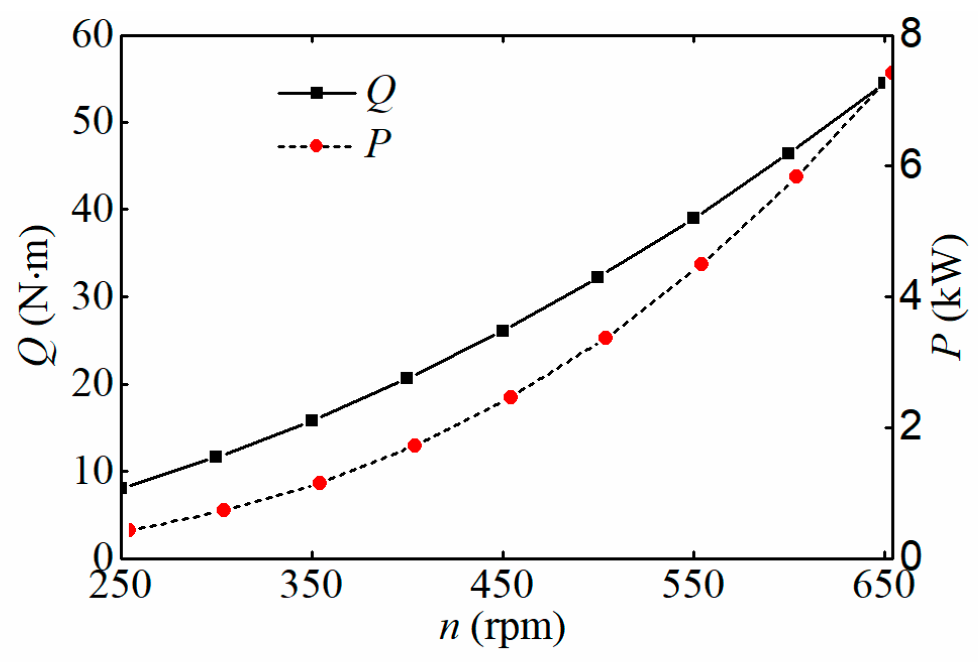
When an underwater vehicle cruises at a low speed, the resistance and thrust required are minor. When an underwater vehicle accelerates, the resistance and thrust required will increase rapidly with the cruising speed [
4]. Therefore, higher cruising speed requires the speed and torque of the drive motor to increase rapidly. In order to ensure the dynamic performance and durability of an underwater vehicle, the drive motor should be able to provide sufficient torque and high efficiency in a wide speed range. Due to the strict requirements of underwater vehicles for dynamic performance, the elements of CRMs can be summarized as follows:
(1) Lightweight, high torque density;
(2) High efficiency in a wide speed and torque range;
(3) Strong overload capacity;
(4) Less torque ripple and vibration noise;
(5) Low-frequency maintenance;
(6) Robustness and high reliability.
Since CRMs have more rotating parts and are also expected to have a compact structure and high torque density, permanent magnet (PM) motors are widely used in underwater vehicles. The advantages of PM synchronous motors and PM brushless DC motors make them the preferred candidate for underwater electric transportation. From the perspective of the overall topologies of motors, there are three solutions to drive CRPs: double contra-rotating motors (DCRMs), a double rotor contra-rotating motor, and an armature rotating contra-rotating motor (ARCRM).
(1) DCRMs: two independent motors rotate in opposite directions to drive two propellers of the CRP, respectively.
A contra-rotating axial flux PM synchronous motor was proposed in [
5] to drive the CRP of a cylindrical underwater vehicle. It can be seen that a magnetic barrier structure of non-magnetic material is used between the two axial flux magnetic circuits to eliminate the mutual influence of the magnetic fields on both sides.
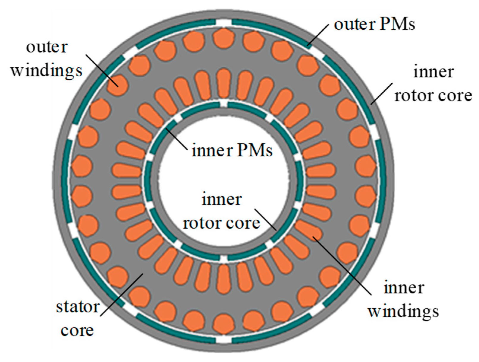
(2) DRCRM: the motor has an intermediate stator and two PM rotors rotating in opposite directions.
Such a DRCRM may be a radial flux motor with inner and outer rotors and a middle stator [
6,
7] or an axial flux motor with dual rotors on both sides and a middle stator [
8]. In [
9,
10,
11,
12], F. Zhang and J. Chen et al. have designed a radial flux PM motor with internal and external rotors rotating in opposite directions and processed the prototype for experimental research. The windings on both sides of this prototype are connected in series, so the armature windings on both sides will be crossed so that the phase sequences on both sides are opposite. An axial flux DRCRM was implemented in [
13,
14,
15,
16], and the windings on both sides were also in series and crossed. The control strategy of this axial flux DRCRM prototype under load variation was discussed in detail. Reference [
17] proposed a novel dual-rotor axial flux induction motor for the contra-rotating propulsion systems of underwater vehicles, and this motor has the capability of self-compensating reaction torque for unbalanced loads. Moreover, this type of CRM can also be used in fields such as aircraft propulsion and wind power generation [
18,
19].
(3) ARCRM: the armature and PM rotors rotate in opposite directions using reactive force. This paper will discuss the motor solution for this topology in detail.
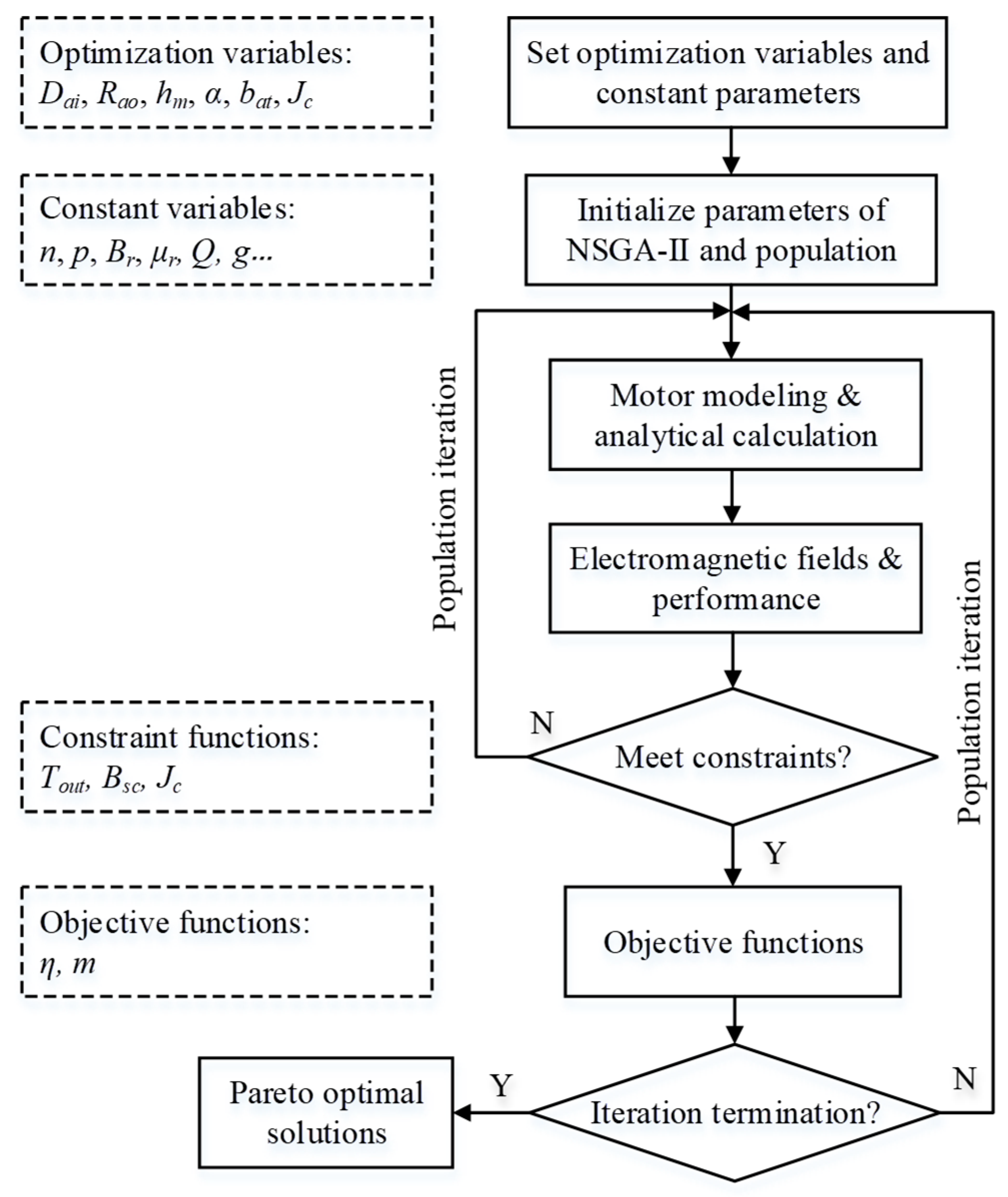
Although multiple topologies for CRMs are mentioned in the references above, there are no papers that conduct comprehensive comparative research on the different topologies of CRMs to investigate which one is more suitable for CRPs of underwater vehicles. This paper aims to explore the magnetic circuit topologies of CRMs for underwater vehicles. First, the analytical design and optimization process of CRMs are presented. Then, the performance and specifications of CRMs with three different topologies will be comprehensively compared and analyzed. Finally, the prototype test of the ARCRM will be carried out.
4. Comparison of Topologies
In this paper, the topologies of DCRMs, the DRCRM, and the ARCRM are presented to drive the CRPs of underwater vehicles. The following will compare these three topologies for CRMs from the perspectives of structure, weight, size, loss, and efficiency.
4.1. Structure
DCRMs: the structure is simple and easy to implement, and no brushes and slip rings are required. Therefore, reliability and robustness are higher. However, the relative speed between the PMs and the armature is only half of that of the ARCRM, resulting in a decrease in electrical frequency. On the one hand, iron loss in the stator core is reduced; however, the properties of the stator core material cannot be fully utilized. Because the magnetic fields of the two motors are independent of each other, both rotors can be assigned to different speeds and torque.
DRCRM: the magnetic fields on both sides will be periodically in parallel and in series. However, for the DRCRM, the speed and load torque of the two contra-rotating rotors may be different, especially during the starting of the motor. The speed difference will distort the magnetic field. In addition, when the torque of the two rotors is different, the current of armature windings on both sides will also be different, which will also cause an imbalance of the rotors on both sides. Since the DRCRM is sensitive to speed or load torque, the robustness of the DRCRM is still poor, and further research is needed on the control strategies. In order to balance the magnetic fields on both sides, both rotors have to be assigned the same speed and torque.
ARCRM: due to the rotation of the armature, the relative speed between the PMs and the armature doubles the rated speed of a single propeller of the CRP, thus contributing to increased power density. However, additional mechanical structures are required to rotate both the PM rotor and the armature, and brushes and slip rings are necessary to power the rotating armature winding. The output torque of the two rotors is always equal due to the reactive force, but the two output ports can be assigned to different speeds.
4.2. Weight and Size
A mass and size comparison of three CRMs with different magnetic circuit topologies is shown in
Table 5. It should be noted that the weight and size of the three CRMs only include the stator and rotor cores, PMs, and winding copper wire, excluding the motor housing and additional mechanical structures. The speeds in
Table 5 are the speeds between the armature and PMs. For convenient comparison, the winding current density and the core magnetic density are designed to be the same.
The ARCRM utilizes the reaction force between the armature and the PM, and only one set of the magnetic circuit is required, so the mass and size of the ARCRM are minimal. The DRCRM has a magnetic circuit topology with inner and outer double rotors and a middle stator. It is difficult to achieve an optimal design of the inner and outer magnetic circuits, simultaneously. Therefore, the DRCRM has the largest mass and size.
4.3. Loss and Efficiency
When the shaft torque is 39 N m, the losses of three CRMs with different magnetic circuit topologies at different speeds are shown in
Figure 19.
As seen from (a), iron loss of the ARCRM is the largest, much higher than that of DCRMs and the DRCRM. This is because the relative speed between the PM and armature of the ARCRM is twice that of DCRMs and the DRCRM, and the electrical frequency is higher. Iron loss of the DRCRM is slightly smaller than that of DCRMs because the magnetic circuits on both sides of the DRCRM are periodically connected in series and in parallel; when the magnetic circuits are connected in series, the losses in the armature yoke are reduced.
As seen from (b), copper loss of the ARCRM is much smaller than that of DCRMs and the DRCRM. This is because the ARCRM uses the reaction force to output torque, so only one set of the magnetic circuit is needed, and the amount of copper wire and copper loss is smaller. In addition, since it is difficult to optimize the inside and outside magnetic circuits of the DRCRM at the same time, the copper loss of the outer magnetic circuit is larger, and the copper loss of the DRCRM will be slightly larger than that of DCRMs.
As seen from (c), PM loss of the DRCRM is the largest, much larger than that of DCRMs and the ARCRM. This is because the PM remanence of the DRCRM outer magnetic circuit is small, but the volume and weight are large, so the eddy current loss in the outer PM is also large.
The efficiencies of three CRMs with different magnetic circuit topologies at different speeds are shown in
Figure 20. When the speed is low, the efficiency of the ARCRM has obvious advantages. However, when the speed exceeds 2000 rpm, the efficiency of the ARCRM gradually lags. Therefore, the ARCRM is suitable for CRPs with low-rated speeds. It can also be seen that DCRMs are consistently slightly more efficient than DRCRMs, but the difference is small.
5. Experiment and Validation
An ARCRM prototype has been designed and fabricated, and the bench test of the ARCRM prototype is demonstrated in
Figure 21. The stator phase currents are continuously monitored using current sensors and an oscilloscope. During operation, real-time temperature measurements are taken at the midpoint of the end winding using infrared thermometers with an accuracy of 1%. The speed and torque sensor boasts a remarkable accuracy of ±0.1%. The ambient temperature during the test is maintained at 20 °C. The motor prototype is powered by a DC power supply through the controller, with the DC voltage set to 210 V. When the ARCRM prototype was driven by the load motor at 2 × 550 rpm, the power consumed by the ARCRM prototype was taken as no-load iron and mechanical losses. The measured copper loss can be obtained from the measured phase current and the measured phase resistance at the operating temperature. Moreover, from the above analysis and calculation, it can be seen that the PM loss of the ARCRM prototype can be negligible. When the rotating speed is 550 × 2 rpm, and the output torque is 39 Nm, the measured losses of the ARCRM prototype are shown in
Table 6.
Based on the motor’s output torque, speed, and losses, it can be calculated that the motor’s efficiency is 93.7%. Under the rated load, the mechanical output characteristics of the ARCRM prototype are shown in
Table 7. The output torque of the inner shaft is 0.4 Nm less than that of the outer shaft because the mechanical loss of the inner shaft is larger due to the friction between the brushes and slip rings. The rotational speed of the inner shaft is 1.4% lower than that of the outer rotor, due to the larger friction and larger inertia of the inner shaft.
In order for the motor prototype to operate reliably during the test, the temperature at the winding end was monitored. The three-dimensional lumped circuit model was used to calculate the transient thermal characteristics of the ARCRM prototype, and this thermal model was solved using ANSYS Motor-CAD software. When the ambient temperature was 20 °C, the prototype worked for 7 h under the rated load, and the calculated and measured winding temperature of the ARCRM prototype is shown in
Figure 22. The maximum temperature measured at the winding end was 109 °C. The insulation grade of the winding copper wire was class H. Therefore, the temperature of the armature windings was always in the safe area, and the prototype remained safe throughout the testing process.
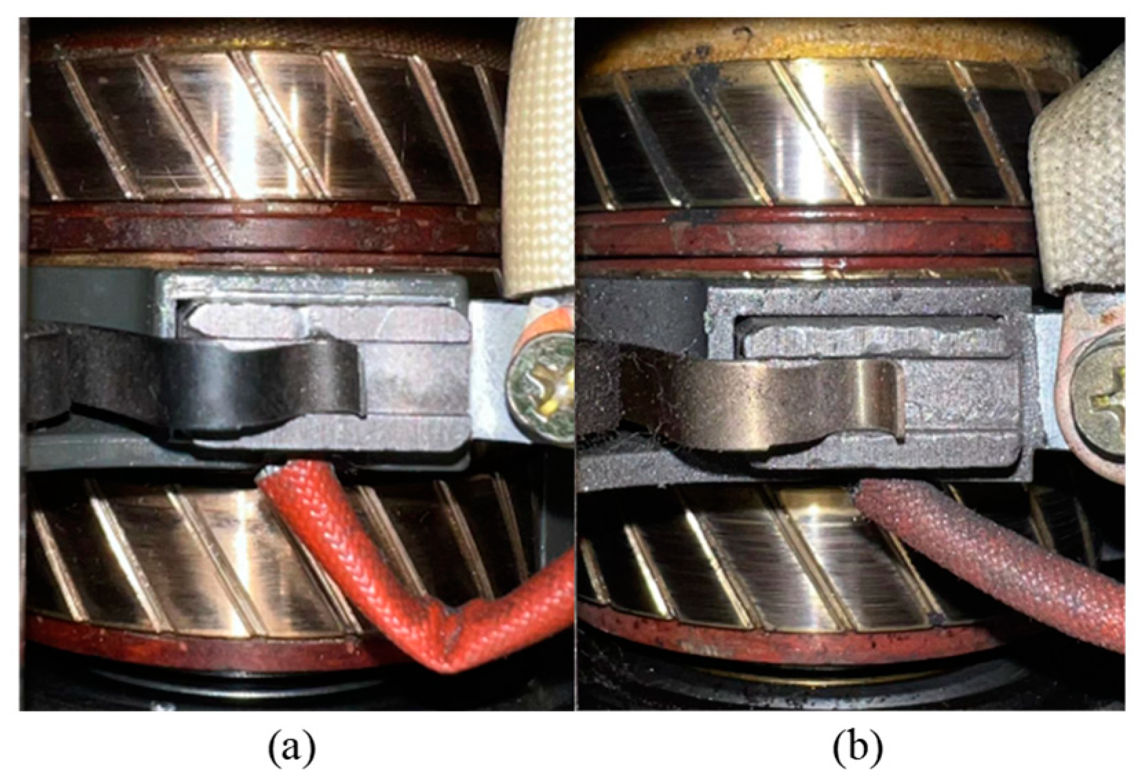
But for the ARCRM, the reliability of brushes and slip rings is the focus of this motor research. Therefore, we tested the ARCRM prototype for 800 cycles, and the test cycle number even exceeded the maximum cycle number allowed by the battery. The slip ring before and after the 7 × 800 h test is shown in
Figure 23. That is to say, the brushes and slip ring still can normally work after 7 × 800 h of operation, which means that the brushes and slip rings are not the factors that limit motor life.


