Article

Experimental and Numerical Study of Lateral Indentation for Pipe-in-Pipe Structures

1
College of Safety and Ocean Engineering, China University of Petroleum (Beijing), Beijing 102249, China
2
CNOOC Research Institute Co., Ltd., Beijing 100028, China
3
China Ship Information Research Center, Beijing 100101, China
*
Author to whom correspondence should be addressed.
J. Mar. Sci. Eng. 2023, 11(1), 98; https://doi.org/10.3390/jmse11010098
Submission received: 30 October 2022 / Revised: 28 December 2022 / Accepted: 31 December 2022 / Published: 4 January 2023

Abstract

:
Pipe-in-pipe (PIP) flowlines have been widely arranged in offshore oil and gas fields for transportation, to achieve a significant thermal insulation capacity and outstanding resistance to external loads. However, the lateral indentation mechanisms of these multilayer pipelines are more complicated than those of single-layer pipelines. In this paper, the change and deformation laws of lateral indentation in the PIP structure were studied by experimental and numerical methods, and three stages of deformation behavior for PIP during lateral indentation were observed. The effects of the diameter and wall thickness of inner and outer pipes on the relationship between the indentation load and lateral indentation were also studied, which provided a reference for the design and analysis of PIP structures.

1. Introduction

During the exploration and development of subsea oil and gas fields, the thermal insulation performance of pipelines is critical to preventing the formation of hydrate in pipelines and improving the high-temperature transportation efficiency of oil and gas. Due to its unique structural characteristics, the PIP system has excellent thermal insulation performance after filling the insulation material between the pipes [1], which is the best solution for developing offshore oil and gas fields with high thermal insulation performance requirements. However, much data show that impact damage seriously affects the safety of submarine pipelines [2]. Subsea pipelines are threatened by occasional loads such as anchoring, ships, and impacts from tribal objects on the platform [3,4]. At present, the design of PIP is similar to that of single-layer pipe, neglecting the special structure of PIP and the combined effect of the internal and external pipes. Therefore, the correct analysis of the collision process of the PIP can help better understand the failure mechanism and improve the design capabilities of the PIP.
A study by Shell found that PIP with an outer diameter greater than 16 inches could be laid directly on the seabed [5] because impact energy could be absorbed by large plastic deformation of the outer pipe without interfering with the inner pipe. This practice has been widely accepted by the industry, which proves the superiority of the PIP as an alternative to pipeline embedding and puts forward higher requirements for the design of the PIP. Zheng et al. [6] explored the possibility of laying pipelines with an outer diameter of less than 16 inches directly on the seabed through experiments, and a method was established to analyze the impact response of PIP [7]. They found that compared with single-layer pipes, PIPs have more complex mechanical properties due to their complex structure, and the difference between them is very significant [8]. The structural reliability of a PIP system is estimated through a second-order series bounds approach [9], and submarine pipeline damage as a result of the impact from falling objects, considering the effect of the seabed, is assessed through finite element modeling [10]. In the relevant design specifications, acceptable pits caused by impacts are given but should not exceed 5% of the diameter value under any circumstances [11]. However, the outer pipe of the PIP is not affected by the circulation load of internal pressure, while the inner pipe is protected by the outer pipe from the influence of external loads. Meanwhile, the pigging process is not affected by the depression of the outer pipe, so it is acceptable to have a large depression in the outer pipe. Then, the impact damage criterion of the outer pipe based on the single-layer pipe criterion can be properly released.
At present, the research on the damage of pipelines by external objects is mostly carried out through methods of experiment and finite elements [12,13,14,15,16,17,18,19,20,21]. Experiments and finite element models have been used to study the behavior of the concave pipe under external pressure [22]. Indentation tests were performed under both quasistatic and dynamic conditions on a 12-inch diameter pipe, and the finite element models for this problem were established and compared with the experimental results [23]. The performance of the preloaded pipeline under local lateral load was studied through tests, and the related finite element simulations and theoretical predictions were carried out [24]. Based on the existing test data, the finite element models of single-layer pipe and PIP were established, to study the influence of external pressure on the relationship between lateral load and local indentation [25]. A two-stage method was proposed to predict the relationship between lateral load and local indentation of the pipe structure filled with cement composite by experimental and finite element methods [26]. The influence of the dimensions of pre-existing corrosion and dent defects on the transverse impact behavior of PIP after service time was experimentally and numerically investigated [27]. A theoretical model is proposed to predict the indentation of PIP by evaluating three stages of PIP indentation [28]. In these studies, most of the pipe ends can rotate freely, which complies with the rotating free boundary condition of the PIP.
Based on reasonable assumptions and under the condition of rigid support, the mechanism of lateral indentation for PIP by the wedge-shaped indenter was studied in this paper, through a series of model tests and the finite element model. Three stages of behavior for PIP under lateral load are observed, and a parametric study based on different diameters and wall thicknesses of pipes was carried out; the results of this investigation are of high reference value for the design of PIP in actual projects.

2. Experimental Study

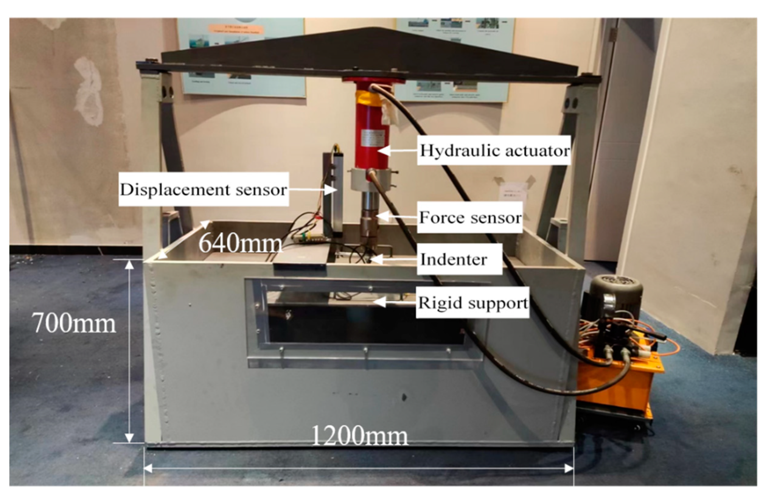
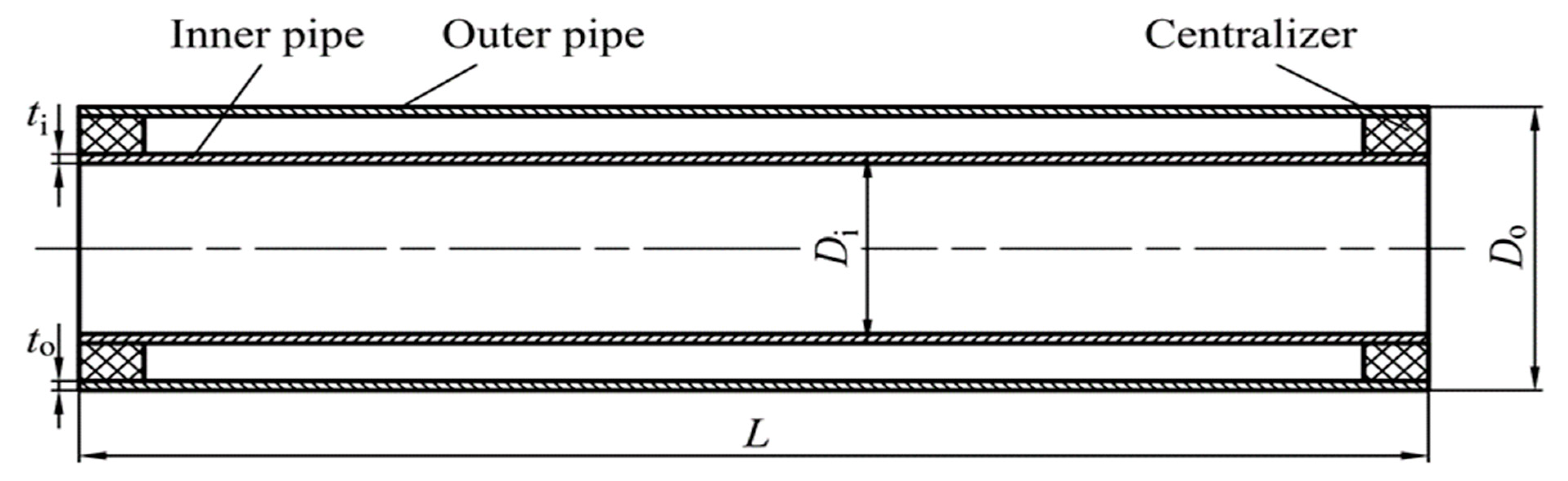
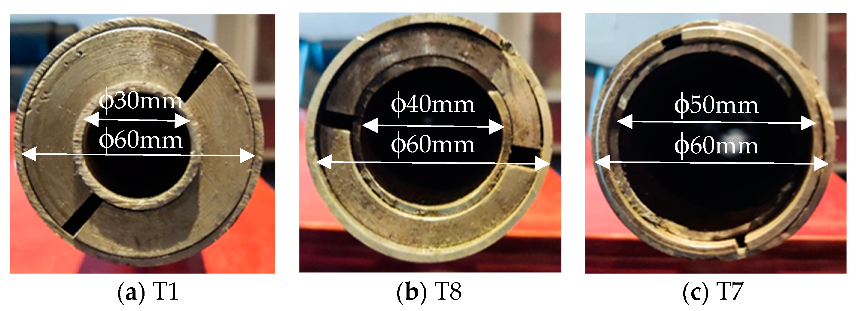
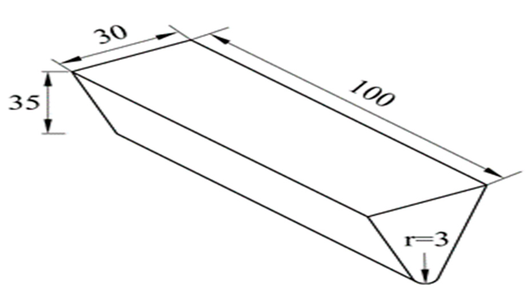
2.1. Model Test Setup

Experimental tests were performed to evaluate the relationship between lateral load and the indentation of PIP specimens under rigid support conditions, which were carried out on a test device, as shown in Figure 1. A hydraulic actuator with a capacity of 10 tons was employed to create a dent defect on the PIP specimen, and the displacement and load signal data during the complete loading process were recorded using dynamic signal acquisition instrumentation.
In this study, 10 PIP specimens of different sizes were used in the experimental tests. The PIP specimens consisted of three components, including the outer pipe (L245 seamless steel), the inner pipe (L245 seamless steel), and the centralizer (L450 seamless steel), as shown in Figure 2; the thermal insulation layer and protective layer were not considered in this study. Considering the actual service status of the submarine pipeline, the inner pipe was centered without axial restraint by adopting the centralizer [29] with a length of 20mm at each end of the PIP specimen (as shown in Figure 3). The complete set of mechanical properties and nominal geometries of the PIP specimens is summarized in Table 1 and Table 2, respectively. The PIP specimens were laterally dented using an ideally rigid wedge-shaped indenter [30] which was made of L450 seamless steel (as shown in Figure 4), considering the wedge-shaped indenter is similar in shape to the front end of a trawler plate or anchor, which are major sources of external loads on pipelines.

2.2. Model Test Process

During the denting process, the PIP specimens rested on a continuous rigid bed with atmospheric internal pressure and free boundary conditions at both ends, and the PIP specimen was accurately located in the fixture with respect to the center line of the indenter to ensure that the dent was imposed exactly at its midsection. The head velocity of the indenter is very low during the loading phase, so the difference between the quasistatic process and the impact process can be ignored.
The steps of the experiment can be divided into the following three parts: (1) The indenter was gently brought down to come into an initial contact to ensure that the boundary condition between the specimen and the rigid bed can be defined as a contact interaction. (2) The indenter was then pushed down to produce a dent up to the desired depth under the displacement control scheme. (3) The indenter was finally pulled back to completely detach the specimen.
To investigate the influence of parameters such as pipe diameter and pipe wall thickness, 10 specimens were considered in this experimental test, as shown in Table 1. The effect of outer pipe diameter was studied in T1 to T3, the effect of outer pipe wall thickness was studied in T4 to T6, the effect of inner pipe diameter was studied in T1, T7, and T8, and the effect of inner pipe wall thickness was studied in groups T6, T9, and T10.

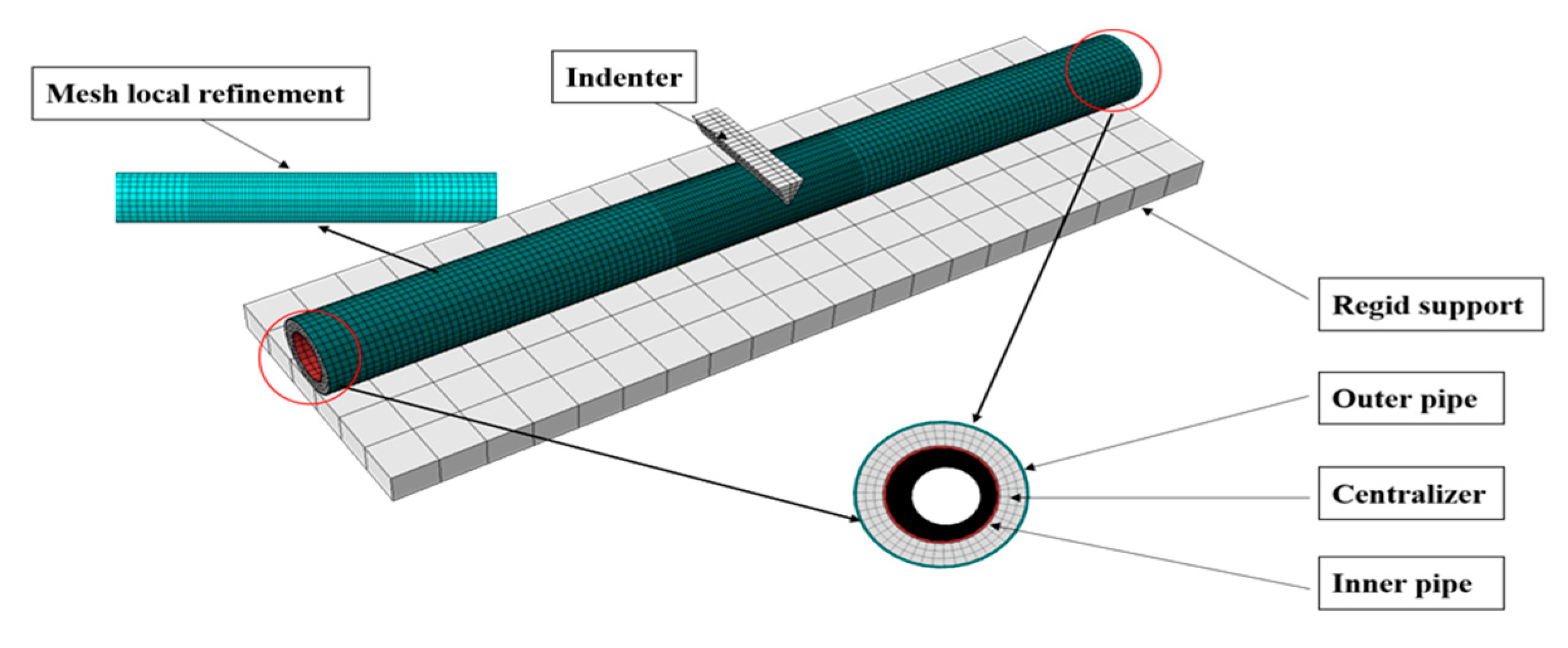
2.3. Numerical Study

To investigate the relationship between the lateral load and the indentation of the PIP under transverse load more comprehensively, a numerical procedure based on the finite element method was developed in ABAQUS software to estimate the lateral indentation by a rigid wedge-shaped indenter. The verified FE models were further used for parametric studies.
The finite element modeling strategy included the main parts such as the rigid support, the indenter, and the PIP specimen, as presented in Figure 5. All components of the FE model were discretized into mesh by using eight-node linear elements (C3D8R). The indenter, rigid support, and centralizer were regarded as rigid bodies. The material model of the steel was elastoplastic, isotropic, and hardened, with mechanical properties as shown in Table 1. An appropriate mesh density was identified by a mesh convergence investigation, as shown in Table 3, and the mesh of the contact area between the indenter and the PIP specimens was refined to improve the calculation accuracy and efficiency. The total numbers of elements and nodes were 16662 and 33438, respectively.

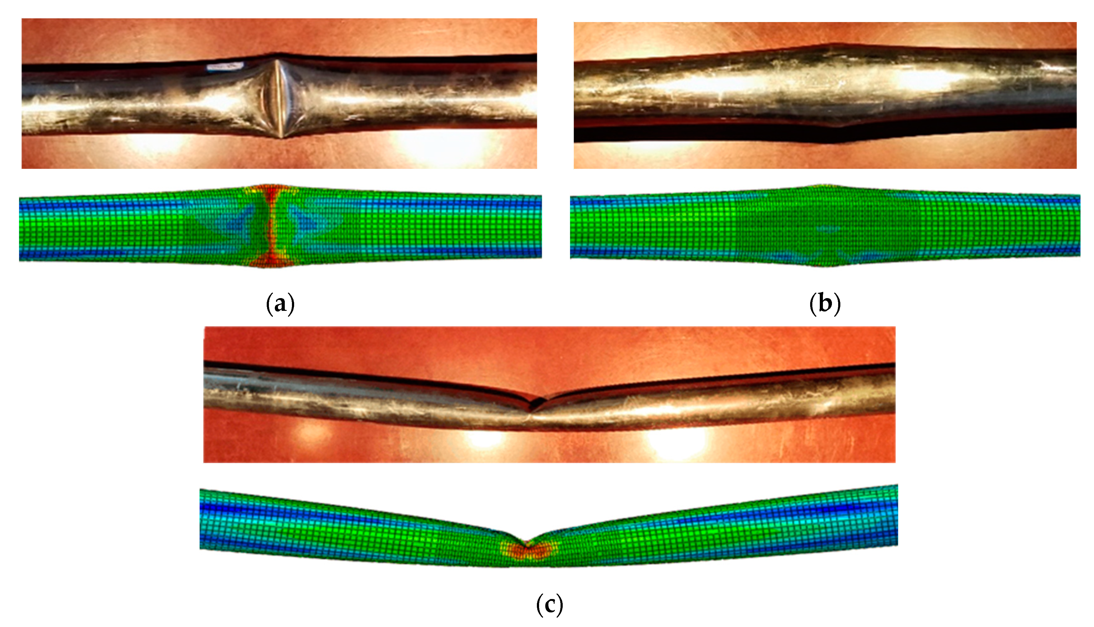
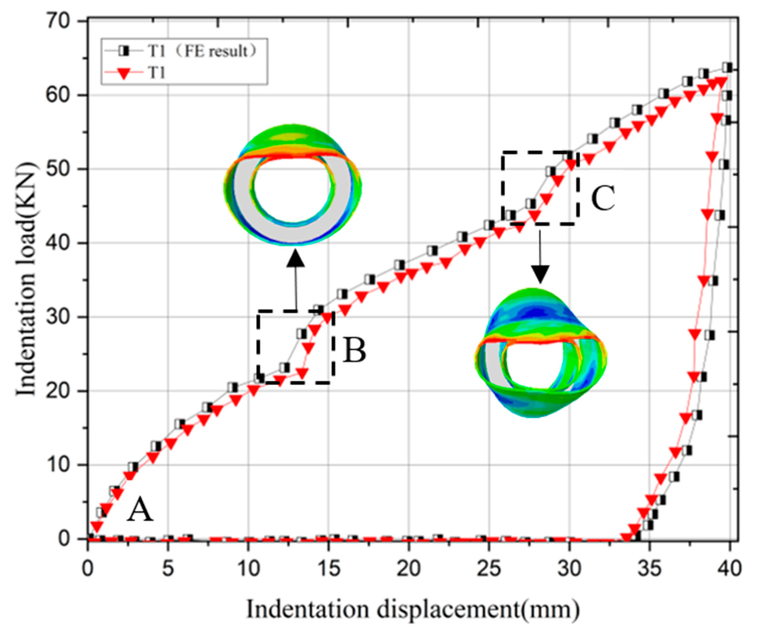
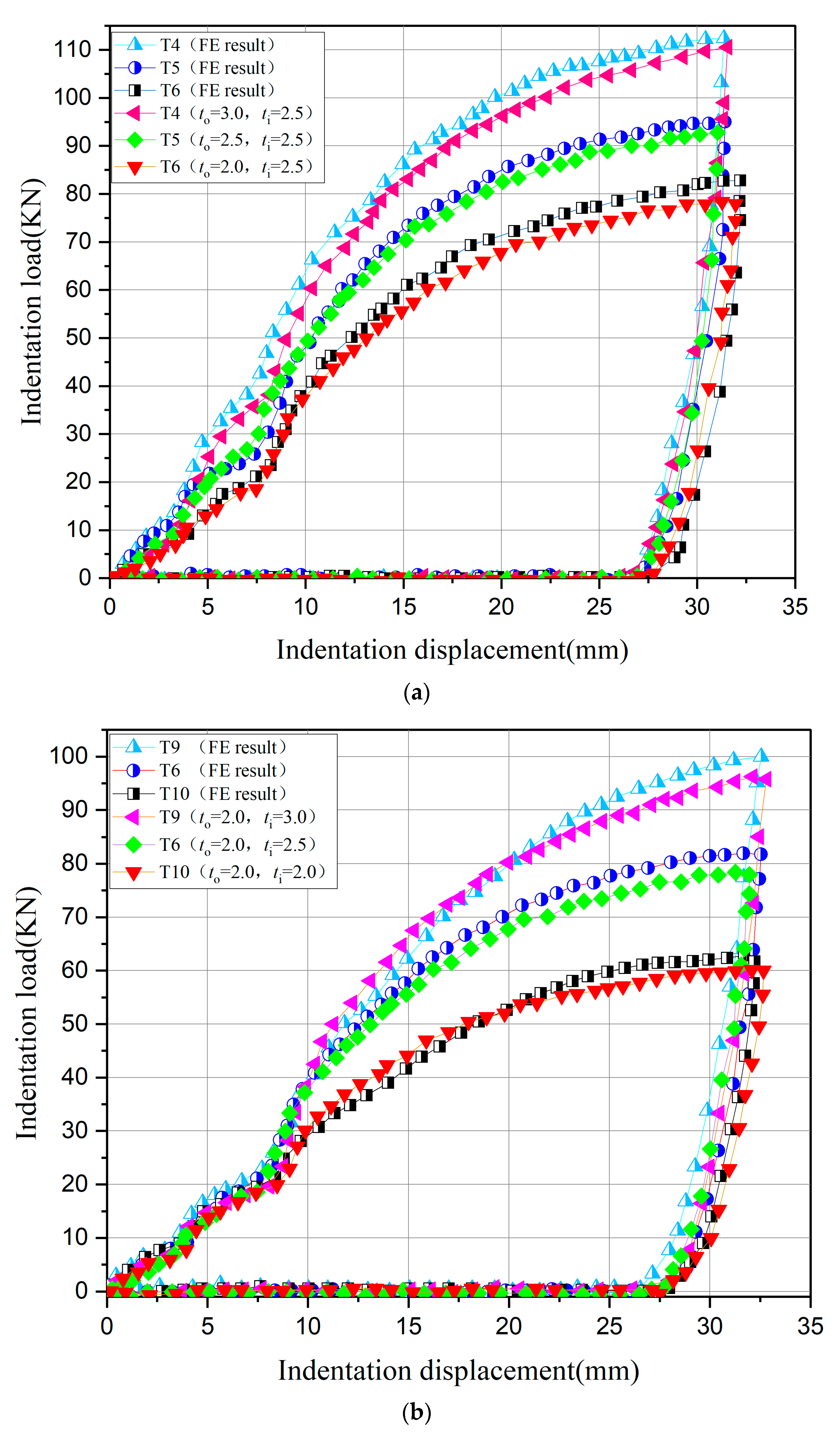
3. Results Discussion

3.1. Comparison of Experimental and Finite Element Results

Figure 6 shows the experimental and finite element simulation of PIP deformation for the T1 group specimen as a result, to prove the rationality of the finite element model. It can be seen from the figure that the deformation results obtained from the test and the numerical simulation were basically consistent. The middle position on the PIP specimen had a “V”-shaped indentation, the lower position was squashed by a rigid support, and without deformation of pipe-in-pipe ends or cock. On the other hand, the relationship between the indentation load and lateral indentation is compared with the experimental and finite element simulation results for the T1 group specimen, as shown in Figure 7. During the unloading phase, the head of the indenter returns to its initial position, while the pipe does not bounce back to its original position due to plastic deformation. By comparison, the margin of error between the two results is less than 6%, and a comparison for all experimental and numerical results is shown in Table 4. Therefore, the finite element model can be used to simulate the experimental process.
The finite element result (black square symbol) and test result (red triangle symbol) for T1 are illustrated in Figure 7. It can be seen that three phases were separated by two critical points B and C during the deformation process, which makes the deformation mechanism of PIP quite different from that of the single-layer pipe. In the first stage (A-B), the upper outer pipe had no contact with the upper inner pipe, and the PIP resisted external forces mainly through the outer pipe while the inner pipe did not deform. In the second stage (B-C), the upper outer pipe made contact with the upper inner pipe, while the lower inner pipe had not touched the lower outer pipe. The PIP resisted external forces by the combined action of the outer and inner pipe, with the difference being that the outer pipe was a rigid support while the inner pipe was a cantilever support. In the third stage (C-D), the lower inner pipe made contact with the lower outer pipe, the PIP resisted external forces by the combined action of the outer and inner pipes under rigid support. The deformation mechanism of PIP is different from that of the single-layer pipe due to the interaction between the outer and inner pipes of PIP during the deformation process. The PIP resisted external forces mainly through the outer pipe under rigid support in stage 1, so it is feasible to simplify the PIP as a single-layer pipe; the PIP resisted external forces mainly through the combined action of the outer and inner pipes in stage 2 and stage 3. The outer pipe resists the external force in the case of rigid support, and the inner pipe resists the external force in the form of a cantilever pipe in stage 2. The outer and inner pipes resist external forces under rigid support in stage 3.

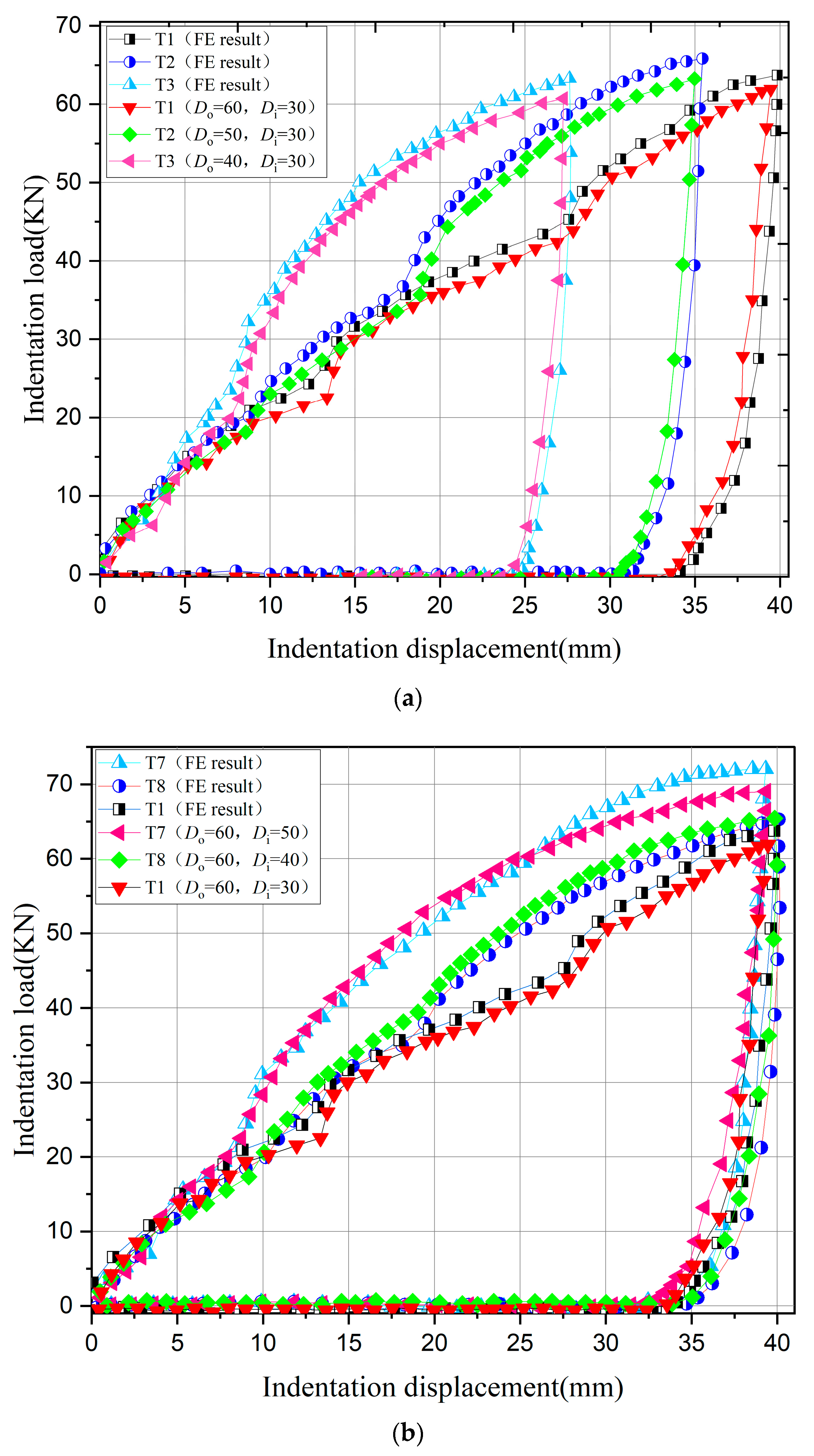
3.2. Parametric Study

The effects of the diameter and wall thickness of inner and outer pipes on the relationship between the indentation load and lateral indentation of the PIP are studied in this section. The influences of outer pipe diameter (Do) and inner pipe diameter (Di) on the load–deformation relationship are shown in Figure 8; the influences of outer pipe wall thickness (to) and inner pipe wall thickness (ti) on the load–deformation relationship are shown in Figure 9. It was found that all of the trends obtained from the numerical simulation for the different specimens showed reasonable consistency with the results measured from the model tests.
When other parameters remain unchanged, the pipe diameters (Do and Di) are more sensitive to the critical points of the PIP at different stages than the resistance of the PIP to external forces (as shown in Figure 8), while the wall thickness (to and ti) are more sensitive to the resistance of the PIP to external forces than the critical points of the PIP at different stages (as shown in Figure 9).
The locations of critical points for all test groups are shown in Table 5. It is obvious from the figure that the distance between the starting point of B (PB) and C (PC) for every test group is almost equal to half of the difference between Do and Di. This shows that in the second deformation stage, the main deformation mechanism is the bending deformation of the inner pipe.

4. Conclusions

The load–deformation relationship is the basis of damage evaluation in structure integrity, and the resistance of the PIP structure under lateral indentation by the wedge-shaped indenter was studied through experimental and numerical methods in this paper. The three stages for indentation of the PIP structure are proposed considering the combined actions of the inner and outer pipes. Critical points are defined as the boundary of different stages based on the deformation and support conditions of the inner pipe, which reflects the special mechanical properties of the PIP structure. Based on the investigations, the following conclusions have been drawn:
(1)
The indentation processes of PIP structures are more complicated than single-layer pipelines, and three stages are observed in both experimental and numerical results.
(2)
The contact between the upper outer pipe and the upper inner pipe is represented by one critical point, and the contact between the lower inner pipe and the lower outer pipe is represented by another critical point. The distance between the two critical points during the deformation process is almost equal to the difference between the radius of the outer and inner pipe.
(3)
The parameters of pipe diameter and wall thickness are sensitive to the critical points for different stages and the resistance of the PIP to external force, respectively.
The conclusion proposed in this paper plays an important role in PIP structure damage evaluation, and more research regarding the influence of insulation material, soil, and boundary conditions will be studied in future work.

Author Contributions

Conceptualization, Y.W.; methodology, C.S.; software, X.W.; validation, J.H. and M.D.; writing—original draft preparation, C.S.; writing—review and editing, Y.W.; funding acquisition, J.H. All authors have read and agreed to the published version of the manuscript.

Funding

This research was funded by the demonstration application project of the Ministry of Industry and Information Technology, grant number MC-201901-S01-01.

Institutional Review Board Statement

Not applicable.

Informed Consent Statement

Not applicable.

Data Availability Statement

Not applicable.

Conflicts of Interest

The authors declare no conflict of interest.

References

  1. Gong, S.; Li, G. Buckle propagation of pipe-in-pipe systems under external pressure. Eng. Struct. 2015, 84, 207–222. [Google Scholar] [CrossRef]
  2. Liu, Y.; Hu, H.; Zhang, D. Probability Analysis of Damage to Offshore Pipeline by Ship Factors. Transp. Res. Rec. J. Transp. Res. Board 2013, 2326, 24–31. [Google Scholar] [CrossRef]
  3. Arash, Z.; Kaare, H.; Farrokh, N. Submarine debris flow impact on pipelines—Part I: Experimental investigation. Coast. Eng. 2008, 55, 1209–1218. [Google Scholar]
  4. Arash, Z.; Kaare, H.; Farrokh, N. Submarine debris flow impact on pipelines—Part II: Numerical analysis. Coast. Eng. 2009, 56, 1–10. [Google Scholar]
  5. Delafkaran, M.; Demetriou, D. Design and Analysis of High Temperature, Thermally Insulated, Pipe-in-Pipe Risers. Presented at the Offshore Technology Conference, Houston, TX, USA, 5–8 May 1997. OTC-8543-MS. [Google Scholar] [CrossRef]
  6. Zheng, J.; Palmer, A.; Lipski, W.; Brunning, P. Impact Damage on Pipe-in-Pipe systems. In Proceedings of the 22th Int Offshore and Polar Engineering Conference, Rhodes, Greece, 17–23 June 2012. [Google Scholar]
  7. Zheng, J.; Andrew, P.; Paul, B.; Gerry, L.; Sun, S. Method to assess the overtrawlability of Pipe-in-Pipe. Presented at the Offshore Technology Conference-Asia, Kuala Lumpur, Malaysia, 25–28 March 2014. OTC-24718-MS. [Google Scholar] [CrossRef]
  8. Zheng, J.; Andrew, P.; Paul, B. Overtrawlability and mechanical damage of Pipe-in-Pipe. J. Appl. Mech. 2014, 81, 031006. [Google Scholar]
  9. Bhardwaj, U.; Teixeira, A.; Soares, C.G. Reliability assessment of a subsea pipe-in-pipe system for major failure modes. Int. J. Press. Vessel. Pip. 2020, 188, 104177. [Google Scholar] [CrossRef]
  10. Tian, Y.; Chai, W.; El Borgi, S.; Zhang, C.; Sun, L.; Xiao, Z.; Fu, D. Assessment of submarine pipeline damages subjected to falling object impact considering the effect of seabed. Mar. Struct. 2021, 78, 102963. [Google Scholar] [CrossRef]
  11. Vestrum, O.; Kristoffersen, M.; Polanco-Loria, M.A.; Ilstad, H.; Langseth, M.; Børvik, T. Quasi-static and dynamic indentation of offshore pipelines with and without mul-ti-layer polymeric coating. Mar. Struct. 2018, 62, 60–76. [Google Scholar] [CrossRef]
  12. Davaripour, F.; Quinton, B.W.; Pike, K. An Assessment on a Subsea Pipeline Subject to a Diagonal Trawl Impact. Appl. Ocean Res. 2021, 110, 102575. [Google Scholar] [CrossRef]
  13. Alrsai, M.; Karampour, H.; Albermani, F. Numerical study and parametric analysis of the propagation buckling behaviour of subsea pipe-in-pipe systems. Thin-Walled Struct. 2018, 125, 119–128. [Google Scholar] [CrossRef] [Green Version]
  14. Li, T. On the formulation of a finite element method for the general pipe-in-pipe structure system: Impact buckling analysis. Int. J. Mech. Sci. 2018, 135, 72–100. [Google Scholar] [CrossRef]
  15. Zhi, X.-D.; Zhang, R.; Fan, F.; Huang, C. Experimental study on axially preloaded circular steel tubes subjected to low-velocity transverse impact. Thin-Walled Struct. 2018, 130, 161–175. [Google Scholar] [CrossRef]
  16. Zhang, R.; Zhi, X.-D.; Fan, F. Plastic behavior of circular steel tubes subjected to low-velocity transverse impact. Int. J. Impact Eng. 2018, 114, 1–19. [Google Scholar] [CrossRef]
  17. Li, W.; Gu, Y.Z.; Han, L.H.; Zhao, X.L.; Wang, R.; Nassirnia, M.; Heidarpour, A. Behaviour of ultra-high strength steel hollow tubes subjected to low velocity lateral impact: Ex-periment and finite element analysis. Thin-Walled Struct. 2019, 134, 524–536. [Google Scholar] [CrossRef]
  18. Lanre, O.; Fauzi, H.; Alastair, W. Effects of impact loads on CRA-Lined pipelines. Ocean. Eng. 2018, 166, 117–134. [Google Scholar]
  19. Qu, H.; Huo, J.; Xu, C.; Fu, F. Numerical studies on dynamic behavior of tubular T-joint subjected to impact loading. Int. J. Impact Eng. 2014, 67, 12–26. [Google Scholar] [CrossRef] [Green Version]
  20. Qu, H.; Hu, Y.; Huo, J.; Liu, Y.; Jiang, Y. Experimental study on tubular K-joints under impact loadings. J. Constr. Steel Res. 2015, 112, 22–29. [Google Scholar] [CrossRef]
  21. Dou, Y.; Liu, Y. Computational investigation of lateral impact behavior of pressurized pipelines and influence of internal pressure. Thin-Walled Struct. 2015, 95, 40–47. [Google Scholar] [CrossRef]
  22. Park, T.-D.; Kyriakides, S. On the collapse of dented cylinders under external pressure. Int. J. Mech. Sci. 1996, 38, 557–578. [Google Scholar] [CrossRef]
  23. Alexander, C. Assessing the Effects of Impact Forces on Subsea Flowlines and Pipelines. In Proceedings of the International Conference on Offshore Mechanics and Arctic Engineering, San Diego, CA, USA, 10–15 June 2007. [Google Scholar] [CrossRef]
  24. Firouzsalaria, S.E.; Showkatib, H. Behavior of pre-compressed tubes subjected to local loads. Ocean. Eng. 2013, 65, 19–31. [Google Scholar] [CrossRef]
  25. Zheng, J.; Palmer, A.; Brunning, P.; Gan, C.T. Indentation and external pressure on subsea single wall pipe and pipe-in-pipe. Ocean Eng. 2014, 83, 125–132. [Google Scholar] [CrossRef]
  26. Qian, X.; Wang, Y.; Liew, J.R.; Zhang, M.-H. A load–indentation formulation for cement composite filled pipe-in-pipe structures. Eng. Struct. 2015, 92, 84–100. [Google Scholar] [CrossRef]
  27. Gao, X.; Shao, Y.; Chen, C.; Zhu, H.; Li, K. Experimental and numerical investigation on transverse impact resistance behaviour of pipe-in-pipe submarine pipelines after service time. Ocean Eng. 2022, 248, 110868. [Google Scholar] [CrossRef]
  28. Sun, C.; Zheng, M.; Soares, C.G.; Duan, M.; Wang, Y.; Onuoha, M.D.U. Theoretical prediction model for indentation of pipe-in-pipe structures. Appl. Ocean Res. 2019, 92, 101940. [Google Scholar] [CrossRef]
  29. Zhang, X.; Duan, M.; Soares, C.G. Lateral buckling critical force for submarine pipe-in-pipe pipelines. Appl. Ocean Res. 2018, 78, 99–109. [Google Scholar] [CrossRef]
  30. Veritas, N. Interference between Trawl Gear and Pipelines; Recommended Practice DNV-RP-F111: Høvik, Norway, 2010. [Google Scholar]
Figure 1. Test device for the lateral indentation of PIP.
Jmse 11 00098 g001
Figure 2. Dimensions of PIP specimens.
Jmse 11 00098 g002
Figure 3. Shape of the centralizer for T1, T7, and T8.
Jmse 11 00098 g003
Figure 4. Dimensions of the indenter.
Jmse 11 00098 g004
Figure 5. Three-dimensional finite element model for PIP specimens.
Jmse 11 00098 g005
Figure 6. Comparison of deformation by test and numerical simulation for T1: (a) upper surface, (b) lower surface, and (c) side surface.
Jmse 11 00098 g006
Figure 7. Relationship between indentation load and lateral indentation for T1.
Jmse 11 00098 g007
Figure 8. Comparison of the load–displacement relationship for different pipe diameters. (a) Different Do for T1, T2, and T3, and (b) different Di for T1, T8, and T7.
Jmse 11 00098 g008
Figure 9. Comparison of the load–displacement relationship for different pipe wall thicknesses. (a) Different to for T4, T5, and T6, and (b) different ti for T6, T9, and T10.
Jmse 11 00098 g009
Table 1. Mechanical properties of the steel used for specimens.
GradeYield Stress
(MPa)
Ultimate Stress
(MPa)
Elasticity Modulus
(GPa)
L254245415206
L450450600210
Table 2. The characteristics of the PIP specimens.
CaseOuter Pipe Inner PipePIP
Do (mm)to (mm)Di (mm)ti (mm)L (mm)
T160.002.0030.002.001300
T250.002.0030.002.001300
T340.002.0030.002.001300
T450.003.0040.002.501300
T550.002.5040.002.501300
T650.002.0040.002.501300
T760.002.0050.002.001300
T860.002.0040.002.001300
T950.002.0040.003.001300
T1050.002.0040.002.001300
Table 3. The mesh convergence investigation.
Number of ElementsRelative Error (%)
638911.1
80863.3
10,5841.5
12,8301.2
14,2710.5
16,6620
Table 4. The comparison of the experimental and numerical results.
CaseRelative Error (%)
T16.01
T210.74
T39.77
T411.63
T59.49
T67.33
T75.49
T89.13
T911.11
T107.29
Table 5. The comparison of the locations of critical points.
CasePIP PBPC 2 × abs ( P C P B D o D i )
Do (mm)Di (mm)(mm)(mm)%
T160.0030.0013.35 26.89 9.73
T250.0030.008.17 17.46 7.01
T340.0030.003.12 7.62 9.95
T450.0040.003.62 8.14 9.71
T550.0040.003.15 7.81 6.76
T650.0040.002.07 7.47 8.04
T760.0050.002.91 8.51 11.98
T860.0040.008.81 17.68 11.32
T950.0040.003.06 8.08 0.32
T1050.0040.003.94 9.08 2.87
Disclaimer/Publisher’s Note: The statements, opinions and data contained in all publications are solely those of the individual author(s) and contributor(s) and not of MDPI and/or the editor(s). MDPI and/or the editor(s) disclaim responsibility for any injury to people or property resulting from any ideas, methods, instructions or products referred to in the content.

