Article

Experimental Study of the Dynamic Shear Modulus of Saturated Coral Sand under Complex Consolidation Conditions

1
School of Mechanical Engineering, Nanjing University of Science and Technology, Nanjing 210094, China
2
Institute of Geotechnical Engineering, Nanjing Tech University, Nanjing 210009, China
*
Author to whom correspondence should be addressed.
J. Mar. Sci. Eng. 2023, 11(1), 214; https://doi.org/10.3390/jmse11010214
Submission received: 15 December 2022 / Revised: 9 January 2023 / Accepted: 11 January 2023 / Published: 13 January 2023
(This article belongs to the Special Issue Advance in Marine Geotechnical Engineering)

Abstract

:
The shear modulus is an essential parameter that reflects the mechanical properties of the soil. However, little is known about the shear modulus of coral sand, especially under complex consolidation conditions. In this paper, we present the results of a multi-stage strain-controlled undrained cyclic shear test on saturated coral sand. The influences of several consolidation state parameters: effective mean principal stress ( p 0 ), consolidation ratio (kc), consolidation direction angle (α0), and coefficient of intermediate principal stress (b) on the maximum shear modulus (G0), the reference shear strain (γr) and the reduction of shear modulus (G) have been investigated. For a specified shear strain level, G will increase with increasing p 0 and kc, but decrease with increasing α0 and b. However, the difference between G for various α0 and b can be reduced by the increase of shear strain amplitude (γa). G0 shows an increasing trend with the increase of p 0 and kc; on the contrary, with the increase of α0 and b, G0 shows a decreasing trend. To quantify the effect of consolidation state parameters on G0, a new index (μG0) with four parameters (λ1, λ2, λ3, λ4) which is related to p 0 , kc, α0, b is proposed to modify the prediction model of G0 in literature. Similarly, the values of γr under different consolidation conditions are also evaluated comprehensively by the four parameters, and the related index (μγr) is used to predict γr for various consolidation state parameters. A new finding is that there is an identical relationship between normalized shear modulus G/G0 and normalized shear strain γa/γr for various consolidation state parameters and the Davidenkov model can describe the G/G0γa/γr curves. By using the prediction model proposed in this paper, an excellent prediction of G can be obtained and the deviation between measured and predicted G is all within ±10%.

1. Introduction

Carbonate soils, most commonly calcium carbonate, are usually divided into three categories based on the calcium carbonate (CaCO3) content: calcareous sand (<50%), siliceous carbonate sand (50–90%), and carbonate sand (>90%) [1]. Carbonate sand, which originates mainly from coral reefs, is referred to as coral sand. Coral sand is mostly distributed in the tropical ocean [2,3] and is the common reclamation material in ocean engineering [4,5,6]. Due to the special formation progress of coral sand, it has the particles features of intraparticle pores, high friction angle, high compressibility, low hardness, and fragileness at high-stress levels [3,7,8,9,10,11], which makes the mechanical properties of coral sand quite different from those of terrigenous sand.
The marine environment is extremely complex including the complexity of coral sand deposition and the dynamic loadings on a coral sand foundation. Waves, tsunamis, and earthquakes can threaten the stability of the coral sand foundation, and then affect the safety of ocean engineering. So it is vital to explore the undrained dynamic response of saturated coral sand. The maximum shear modulus G0 and the reduction of shear modulus (G/G0) from small to large strain range are the essential parameters in seismic response analysis studies. Many researchers have studied the dynamic shear modulus of silica sand. The maximum shear modulus G0 is referred to as the shear modulus at small strain (γa < 10−6), which is a key parameter in the prediction of G. The previous researches reveal that the value of G0 is related to the void ratio e and the effective confining pressure σ 0 [12,13,14,15,16]. The void ratio reflects the influence of soil property on G0, and the effective confining pressure characterizes the effect of consolidation condition on G0. Hara et al. [17] obtained the G0 of cohesive soils by using shear wave velocity Vs in laboratory and in situ tests (G0 = ρVs2), and a unique correlation is established between G0 and shear strength Su. Hardin and Kalinski [18] investigate the shear modulus of gravelly soils including uniform and graded crushed limestone gravel, graded river gravel, standard Ottawa and crushed limestone sands, and gravel–sand–silt mixtures. The modified three-dimensional constitutive equations for the elasticity of particulate materials are used to evaluate G0 for various types of soils. Goudarzy et al. [19,20] explored the effect of the non-plastic fines content of granular on the maximum shear modulus. The G0 of clean Hostun sand and Hostun sand mixed with 5%, 10%, 20%, 30%, and 40% fines are analyzed. To evaluate the influence of fine content on G0, the equivalent void ratio (e*) is introduced to replace e in the Hardin model. The modified model has a good prediction for the Hostun sand. Yan et al. [21] investigated the small-strain shear modulus of unsaturated silty-fine sand. They find that there exists an optimum saturation (Sr)opt in silty-fine sand. G0 reaches its maximum value when the silty-fine sand is in optimum saturation and an improved prediction model for G0 is proposed for sand under different saturation degrees.
Iwasaki et al. [22] evaluated the degree of shear modulus reduction by using two types of equipment. The test results show that the shear modulus at 10−4 shear strain amplitude measured by different equipment is identical, and a simplified procedure for prediction G is proposed. Lanzo et al. [23] reported the test results of two reconstituted grains of sand and three laboratory-made clays. The results indicated that with the increase of σ 0 and the over-consolidation ratio (OCR), the normalized shear modulus reduction curve (G/G0γa) generally increases. Furthermore, with the increase of plasticity index (PI), the effect of σ 0 , and OCR on shear modulus reduction become small. Senerakis et al. [24] found that the G/G0γa of volcanic sands were more linear than those of quartz sands. This trend was more pronounced at lower σ 0 and at higher values of the coefficient of uniformity (Cu). The parameters of σ 0 and Cu may not be used in the modified hyperbolic model to quantify the rate of modulus reduction, and it is probably due to the unique fabric of volcanic sands. Chen et al. [25] investigated the characteristics of shear modulus reduction under isotropic and anisotropic consolidations for silt. The correlations between G/G0 and γa for various complex stress conditions are distinct. However, the correlation between G/G0 and γa/γr is identical regardless of the consolidation state parameters.
In recent years, with the rise of ocean engineering, the mechanical properties of coral sand become the research focus in marine geotechnical engineering. Controlling the quality of hydraulic filling materials is the key to ensuring the construction safety of marine structures [6]. For soil mass, the shear strength is always the most critical mechanical parameter. Many studies have confirmed that the particle size and confining pressure can affect the shear strength of coral sand [26,27]. However, these researchers focused on the shear characteristics of soils under monotonic shear. Since large-scale deformation of saturated coral sand has been observed in the 1993 Mw 7.7 Guam earthquake [28], the 2006 Mw 6.7 and Mw 6.0 Hawaii earthquakes [29], and the 2010 Mw 7.0 Haiti earthquake [30], the dynamic characteristics of coral sand foundation also need further discuss, and the dynamic shear modulus of coral sand is the most essential, which can establish the constitutive relation and guide the construction of offshore engineering. In fact, engineers have long been concerned about the maximum shear modulus together with the dynamic shear modulus reduction of coral sand foundations. Giang et al. [31] found that particle shapes could affect G0. Due to the unique particle characteristics of coral sand, the G0 of coral sand is much higher than that of silica sand. The previous prediction model will underestimate or overestimate the G0 of coral sand. Chen et al. [32] carried out different types of strain-controlled undrained cyclic triaxial tests, and a correlation-function-based method is proposed to calculate the secant shear modulus, which shows a good prediction of shear modulus attenuation. Wu et al. [5] studied the dynamic shear modulus of saturated marine coral sand with different fines contents (FC) and relative densities (Dr). To quantify the influence of both parameters mentioned above, the equivalent skeleton void ratio e*sk is introduced, and a unique correlation can be observed between G0, σ 0 , and e*sk. However, most of these studies focused on the effect of soil properties such as confining pressure, relative density, void ratio, and coefficient of uniformity on the shear modulus of coral sand. The mechanism of the effect of consolidation state parameters on the shear modulus reduction is still unclear.
In this paper, we present a comprehensive experimental study of the maximum shear modulus and the reduction of the shear modulus with increasing shear strain. The influence of effective mean principal stress ( p 0 ), consolidation ratio (kc), consolidation direction angle (α0), and coefficient of intermediate principal stress (b) on the shear modulus of coral sand is systematically investigated. The cyclic deformation characteristics of the specimens are also analyzed. The cyclic deformation properties of the specimens were also analyzed. The conclusions drawn in this study can lead to a better understanding of the undrained cyclic behavior of saturated coral sand and provide some key parameters for the analysis of the seismic response of coral sand foundations.

2. Test Materials and Apparatus
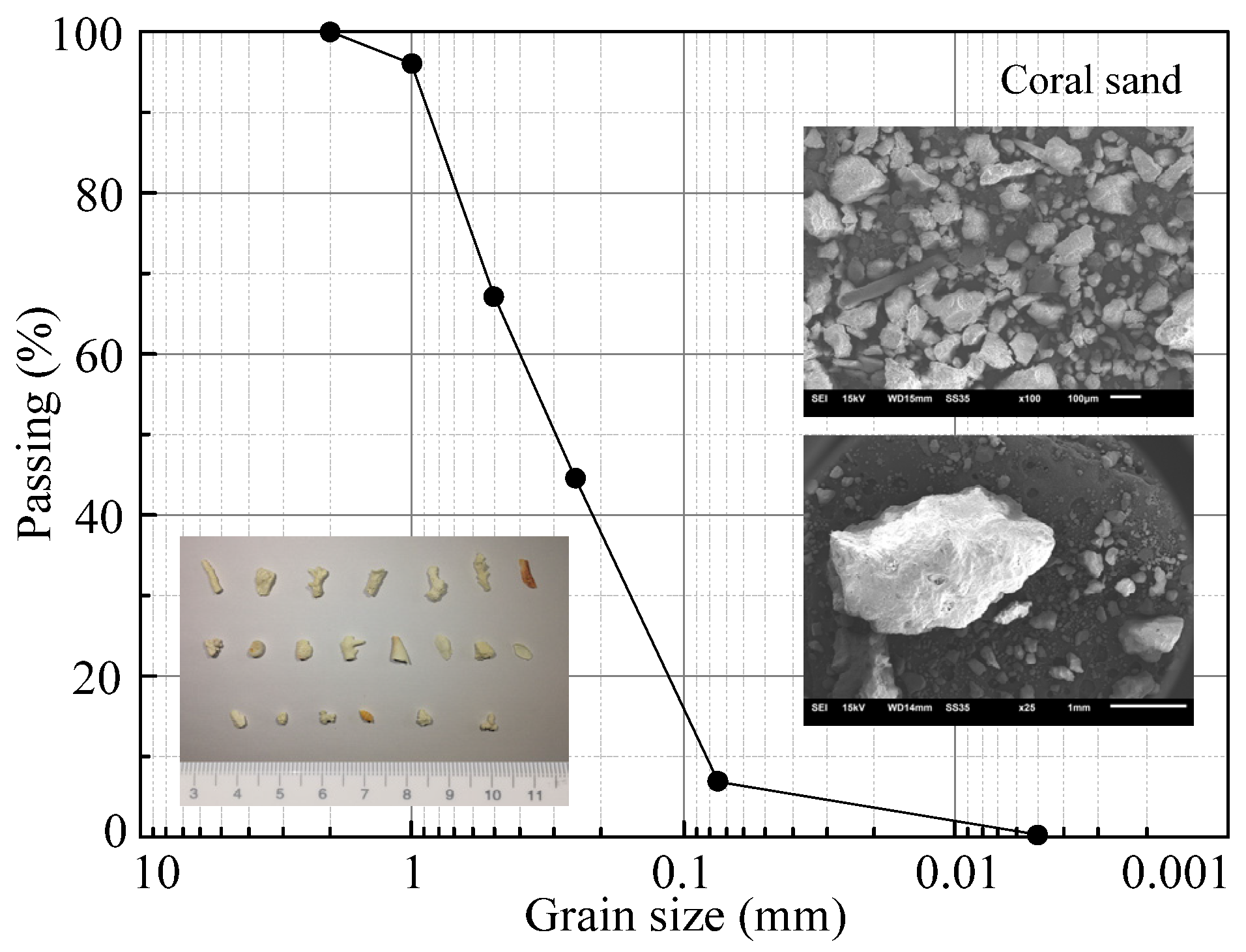
2.1. Test Material

The tested coral sand material is sourced from the Nansha Islands, South China Sea. Figure 1 shows the particle distribution curve, photograph, and scanning electron microscope (SEM) picture of tested coral sand. The particle shape of the tested coral sand varies from long strips to round, and some coral and marine fragments can also be observed. From a micro perspective (the SEM picture), the tested coral sand particles have rough surfaces and are attached to fine particles. The specific gravity (Gs) of coral sand is 2.80, maximum and minimum void ratio (emax, emin) is 1.72 and 0.99 respectively, according to the ASTM standards of D4253-14 and D4254-14 [33,34]. Since the maximum particle size used in the specimen cannot be greater than 1/6 to 1/7 of the specimen diameter, the maximum particle size of coral sand used in this test is 2 mm. For the particle distribution curve used in this test, the mean particle size (d50) is 0.31 mm, coefficient of uniformity (Cu) and curvature coefficient (Cc) is 4.67 and 0.86 respectively. Following the Unified Soil Classification System [35], the tested coral sand is classified as poorly graded sand (SP).

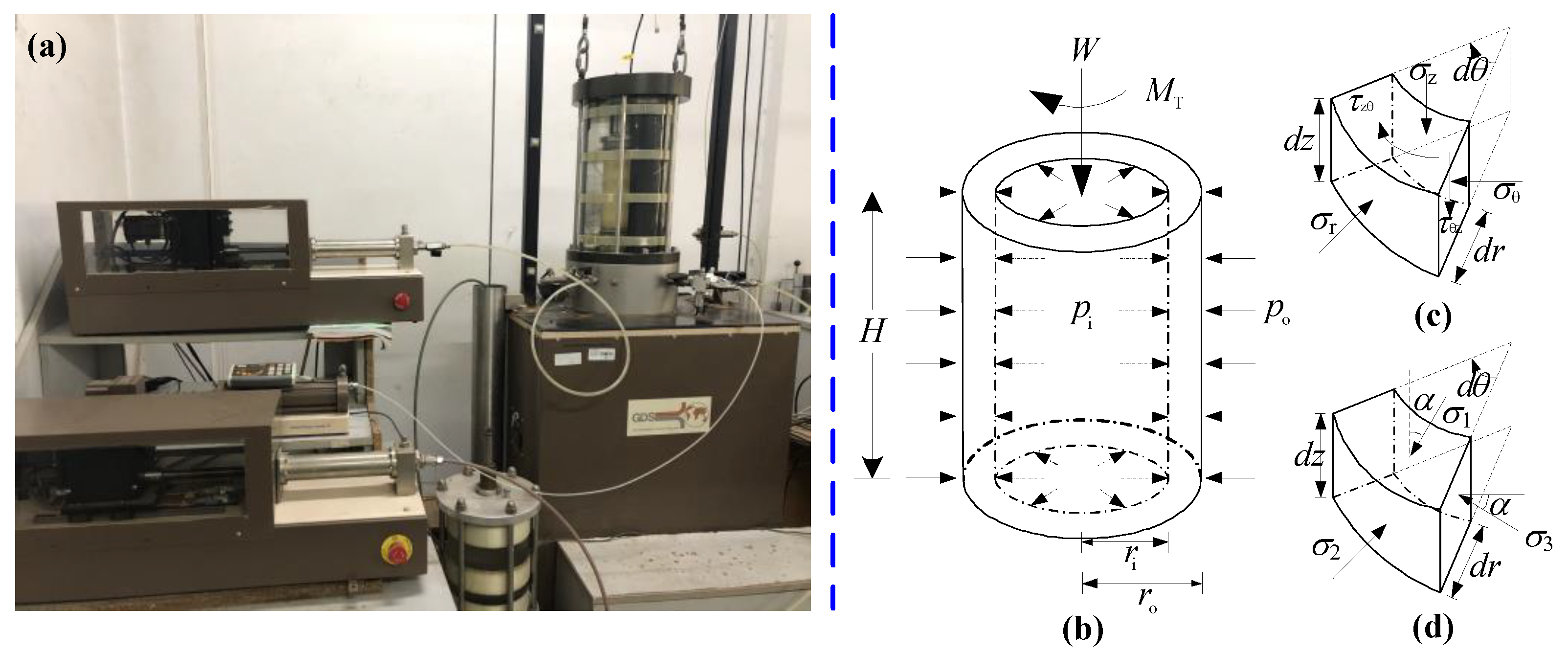
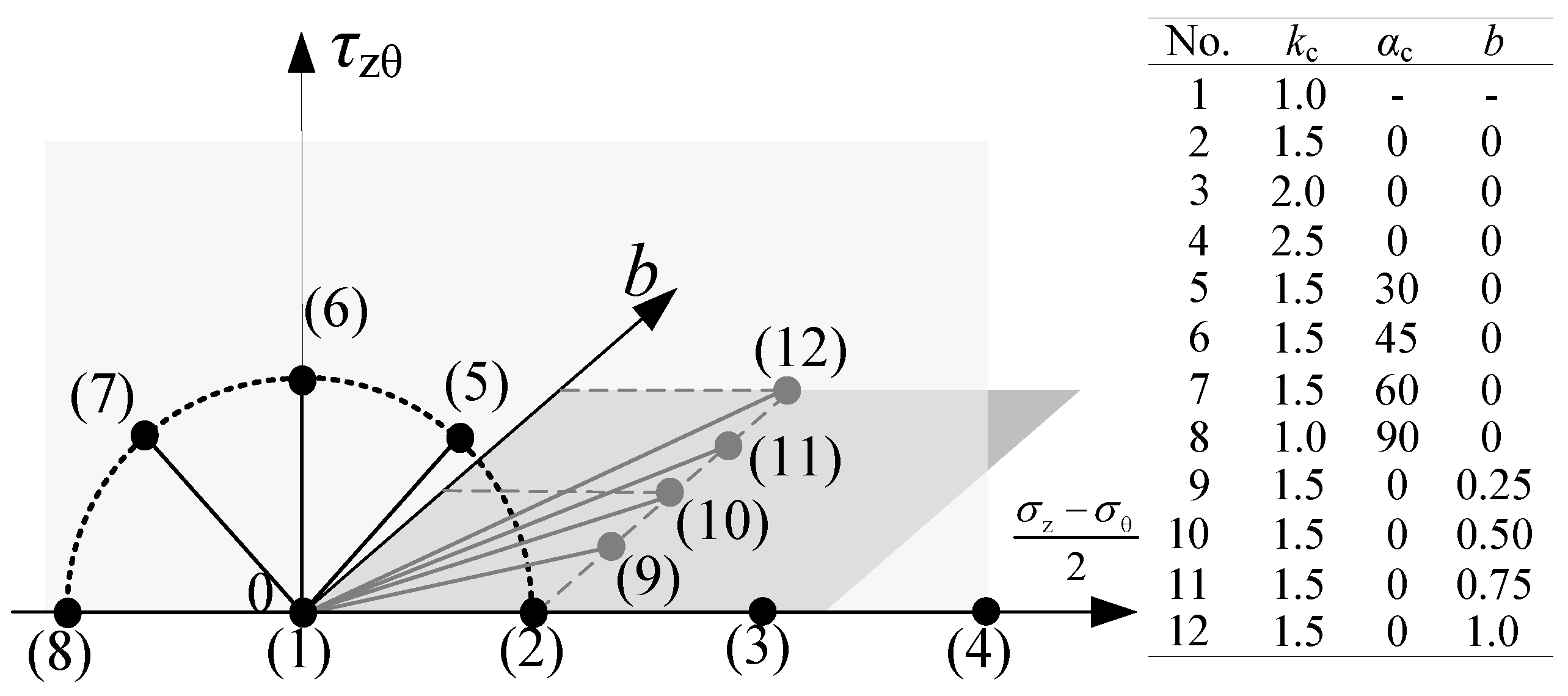
2.2. Test Apparatus and Stress Distribution

An advanced hollow cylinder torsional shear apparatus manufactured by GDS Instruments (Hook, Hampshire, United Kingdom) is used in this study [Figure 2a]. The instrument is composed of four parts: pressure chamber, host, pressure controller, and data acquisition system. This apparatus can dynamically and independently control the axial load (W), torque (MT), outer cell pressure (po), and inner cell pressure (pi). The distributions of these four cyclic loadings on the specimen are shown in Figure 2b. Table 1 gives the performance parameters of the GDS apparatus including the capacity, deviation, and precision of the sensors. The four corresponding stress components (vertical stress σz, radial stress σr, circumferential stress σθ, and torsional shear stress τ) and three principal stresses (σ1, σ2, σ3) are illustrated in Figure 2c,d. Table 2 gives the equations of data interpretation for all consolidation loadings, the stress components, and the consolidation state parameters. More details about this apparatus can be found in the literature [25,36,37].

3. Specimen Preparation, Saturation, and Consolidation

The hollow cylinder specimen in this study has a height of 200 mm and an inner and outer diameter of 60 mm and 100 mm. The specimen preparation method can significantly affect the mechanical properties of soil [38,39]. To ensure the uniformity of each specimen, the dry deposition method was adopted for preparing the coral sand specimens. The specimens were prepared by pouring the dried sand in seven layers into the hollow space between two molds via a funnel with a near-zero falling head. To investigate the influence of consolidation characteristic parameters on the dynamic shear modulus, the target initial relative density (Dr) of each specimen is 45%, and the corresponding void ratio is 1.355. The actual relative density after consolidation (Drc) for all specimens ranged from 49.18% to 52.88% (see Table 3), and the corresponding void ratio ranged from 1.334 to 1.361. Note that the difference in the relative density before and after the consolidation is about 5%. It is probably due to the high compressibility of coral sand.
After the specimen preparation was complete, the specimen was carefully set in the pressure chamber. The combination method of flushing CO2 and de-aired water was used to make the specimen attain preliminary saturation, then applying back pressure (pb) to 400 kPa in three steps (end of step I: pb = 100 kPa, po = pi = 110 kPa; end of step II: pb = 200 kPa, po = pi = 210 kPa; end of step III: pb = 400 kPa, po = pi = 410 kPa); until the Skempton’s B-value ≥ 0.97, which is a criterion indicating the specimen is completely saturated. The effective stress of the specimen always remains at 10 kPa during the saturation. After saturation, the specimens were firstly isotropically consolidated under different effective mean principal stress p 0 (50, 100, 200, 300 kPa), and then anisotropically consolidated according to the scheme under various consolidation ratios of major and minor principal stress kc (1.0, 1.5, 2.0, 2.5), direction angle of principal stress α0 (0°, 30°, 45°, 60°, 90°) and coefficient of intermediate principal stress b (0, 0.25, 0.5, 0.75, 1.0). The whole consolidation process lasts for several hours. When the strain components and back pressure volume are stable, the coral sand specimen can be considered wholly consolidated. The consolidation stress paths are shown in Figure 3. The values of W, MT, po, and pi for each consolidation condition are illustrated in Table 3. The saturation and consolidation for all the tested specimens were performed following the procedures in the ASTM standard [40].

4. Multi-Stage Strain-Controlled Undrained Cyclic Shear Tests

It should be noted that under high-frequency seismic load, the saturated sand will generate excess pore water pressure, which will lead to the reduction of effective stress and the destruction of the foundation. In order to truly simulate the dynamic response of saturated coral sand under seismic load in the marine environment, it is more reasonable to choose the undrained test in this study. For each consolidation condition, multi-stage strain-controlled undrained cyclic torsional shear tests were performed. Table 3 lists the detailed procedure for the strain-controlled undrained cyclic shear test. 17 to 20 stages of sinusoidal cyclic strain were applied to each specimen, with ten cycles per stage. ASTM D5311/D5311M standard recommended that a range of cyclic loading frequency f = 0.1–2.0 Hz, and the frequency of 1.0 Hz is preferred [40]. Moreover, many previous studies also used a 1.0 Hz sinusoidal wave as the cyclic loading condition to observe the dynamic response of soil under earthquake events [41,42,43]. So, the cyclic loading frequency of 1.0 Hz was adopted for all tests in this study to simulate the seismic load. The torsional strain amplitudes change from small strain (0.001%) to large strain (0.5%). After each cyclic loading phase, the specimen was reconsolidated to the initial stress state for 10 min. This stage is intended to dissipate the excess pore water pressure (EPWP) at a large shear strain, which could affect the test result of the next stage [44]. During the drained re-consolidation stage, the volume of the specimen decreased, leading to a slight increase in Dr. However, the value of G can be less affected by density for multi-stage cyclic loading, which has been confirmed in literature [41,45]. Efforts have been made during the whole experiment process to ensure the consistency of the specimen to the greatest extent.

5. Test Results and Analysis

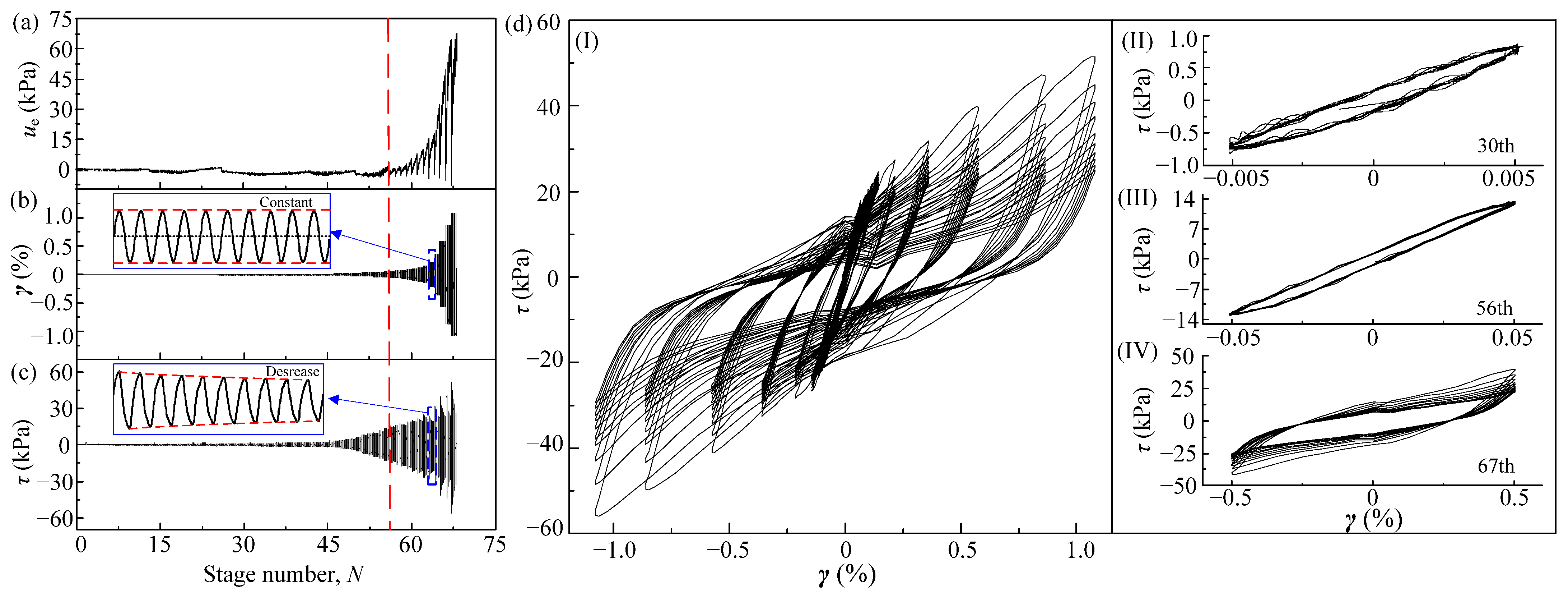
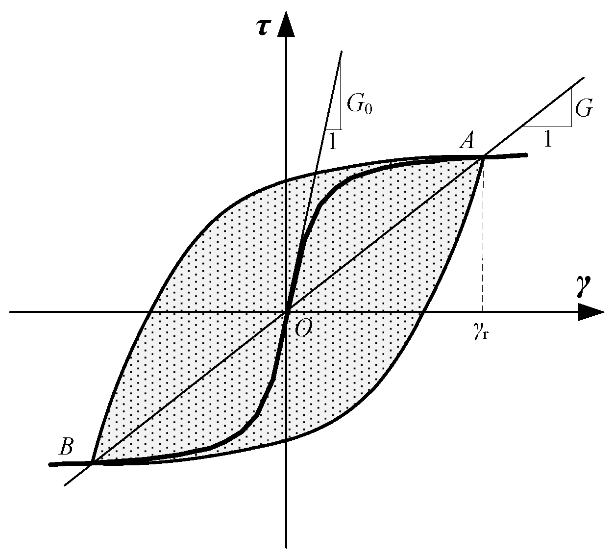
5.1. Typical Results of The Strain-Controlled Test

Figure 4 shows the typical test result of strain-controlled undrained cyclic torsional shear (No. 01). As the number of stages increases, the shear strain amplitude (γa) and shear stress amplitude (τa) also increase slowly, but not significantly. When γa reaches 1 × 10⁻⁴, the shear stress has an observable development; when the strain reaches 2.89 × 10⁻⁴, the EPWP (ue) starts to develop significantly (more than 2 kPa). Note that the test is strain-controlled, τa for each cycle stage is constant and can eventually return to the origin. However, the cyclic shear stress may decrease during the cycle stage and produce deviation in the end. Figure 4d(I) depicts the development of the shear stress-strain relationship in the strain-controlled undrained cyclic shear test. With the increase of shear strain magnitude γa, the area of the hysteresis loop becomes large, indicating the gradual decrease in shear strength of the coral sand specimen. Figure 4d(II–IV) is the stress-strain relationship corresponding to the shear strain magnitude of 5 × 10⁻⁵, 5 × 10⁻⁴, and 5 × 10⁻³, respectively. The nonlinear of the stress-strain relationship becomes obvious with the increase of γa, and the shear stress amplitude gradually decreases at large γa. This is because a large strain amplitude causes the EPWP of the coral sand specimen to rise and then increase the flow properties of the soil.
Figure 5 demonstrates the idealized shear stress-strain response of soil under cyclic torsional shear loading. The strain-dependent secant shear modulus is used to study the modulus attenuation of coral sand in this test, which is commonly used in previous studies.

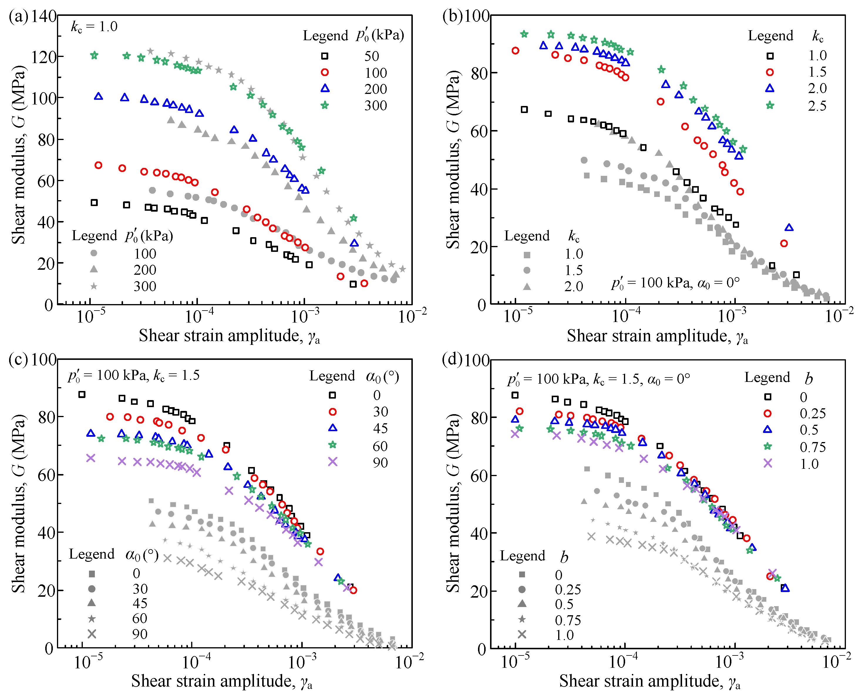
5.2. The Characteristics of Dynamic Shear Modulus under Various Consolidation Conditions

Figure 6 presents the relationship between G and γa of saturated isotropically and anisotropically consolidated coral sand for the undrained cyclic torsional shear tests. Clearly, G decreases with the increase of γa for all tests, and various consolidation state parameters ( p 0 , kc, α0, b) have different effects on shear modulus reduction. Under isotropic consolidation, G increases with increasing p 0 for a specified shear strain level, and the rates of shear modulus reduction for various p 0 are almost the same. This is consistent with the test result of Kokusho [13] for Toyoura sand and Chen et al. [25] for Nanjing fine sand. However, under anisotropic consolidation, the effect of kc, α0, and b on the shear modulus reduction shows different regular. When other parameters ( p 0 , α0, b) are constant, G increases with the increase of kc. Note that with the increase of kc, the difference between G becomes small. This can be assumed that when kc > 1.0, the void between coral sand particles begin to decrease gradually, which leads to the rearrangement of particles and the increase of friction between particles, making the shear modulus of coral sand increase significantly. However, when kc continues to increase, the rearrangement between particles becomes more and more difficult, and the static shear stress only increases the friction between particles. As a result, the differences between the shear modulus for the various kc become small as the kc continues to increase. Yuan et al. (2005) and Sun et al. (2013) obtained similar test results on silt, silty clay, and sludgy soil. They also proposed a prediction model to describe the trend of G0 with the increase of kc. [46,47] On the contrary, when α0 and b increase, the shear modulus for a specified shear strain level shows a decreasing trend. However, this gap becomes smaller as the shear strain increases. When shear strain is over 6 × 10⁻⁴, there is no obvious difference of G value under various α0 or b. Figure 6 also illustrates the relationship between G and γa of saturated Nanjing fine sand under similar consolidation conditions, which is shown in gray symbols. The physical properties of this sandy soil can be found in Chen (2016). It is clear that the regular shear modulus reduction is quite similar for both sandy soils. However, the development trend of the shear modulus for Nanjing fine sand is significantly lower than that for coral sand under the same kc, α0, b. However, for the same p 0 , the modulus attenuation trend of the two sandy soils is quite close.

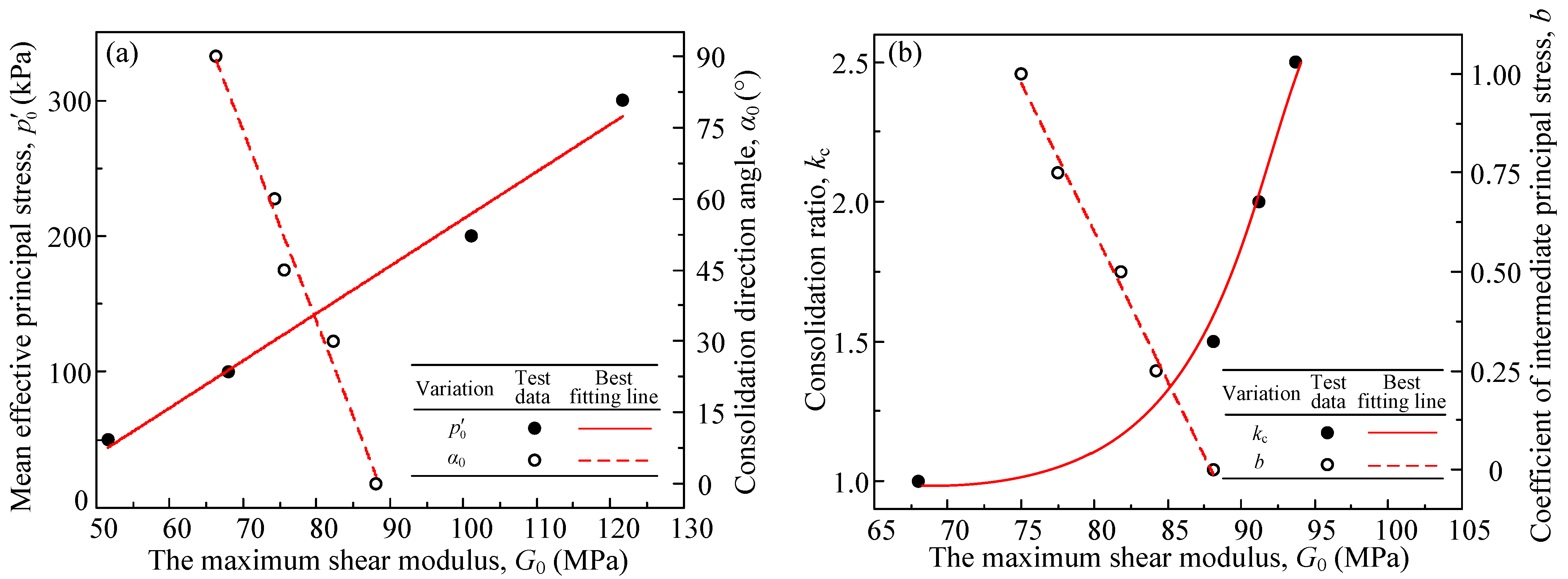
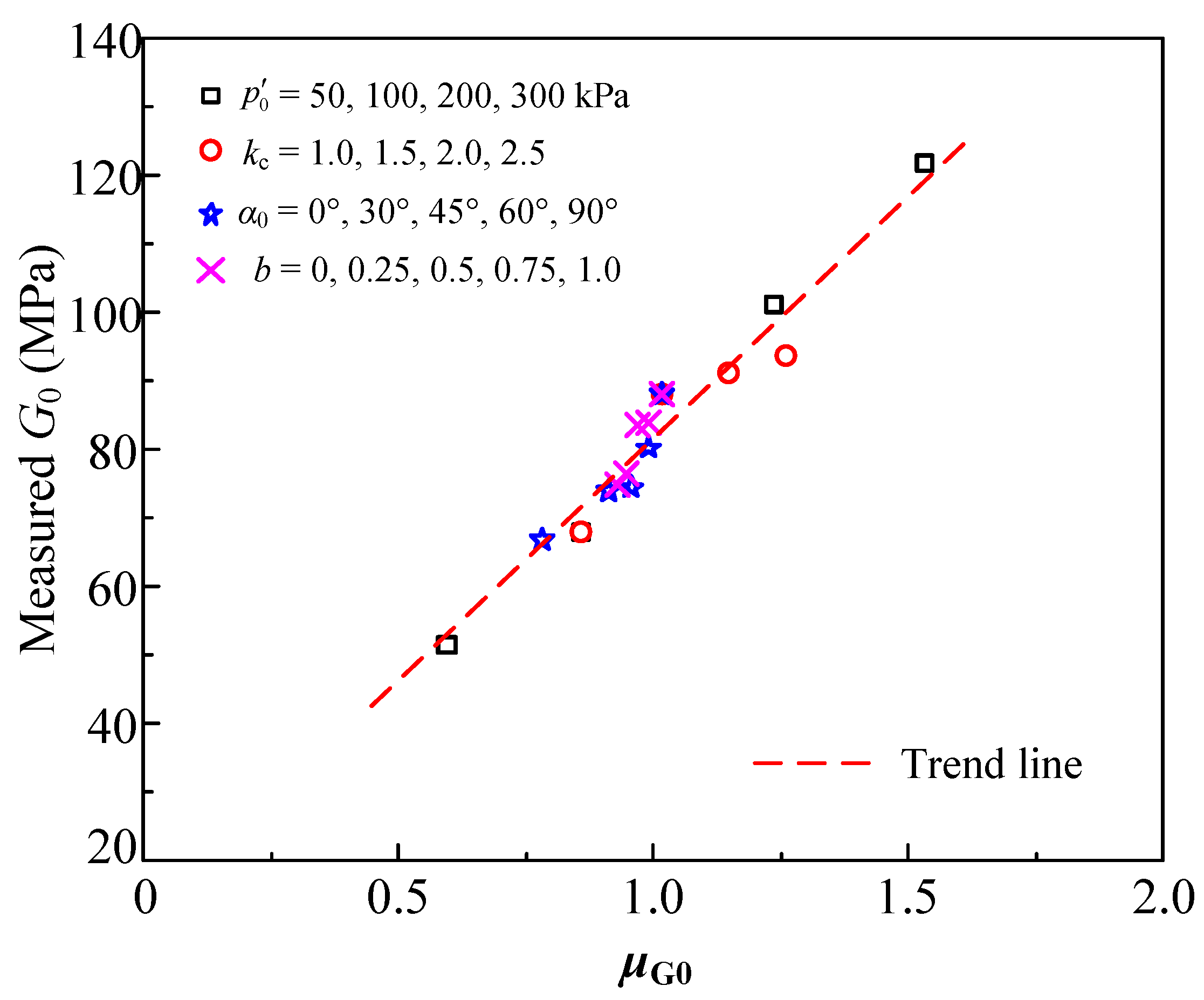
5.3. The Maximum Dynamic Shear Modulus under Various Consolidation Conditions

The maximum dynamic shear modulus G0 is an essential parameter in the undrained dynamic shear response of saturated sandy soils. G0 is generally considered as the shear modulus at a small strain (less than 10−6). To investigate the correlation between G0 and various consolidation state parameters, a total of 15 strain-controlled undrained cyclic torsional shear tests were performed using the GDS hollow cylinder apparatus. Due to the limited testing accuracy of this apparatus, the dynamic shear modulus less than 1 × 10⁻⁵ is hardly measured, and G0 cannot be obtained directly. However, according to the hyperbolic model proposed by Hardin and Drnevich [48], G0 can be calculated by
G 0 = lim γ 0 1 a 1 + b 1 γ ,
where a1 and b1 are the linear fitting parameter. Hardin also gives the model to predict the G0 of sandy soils:
G 0 = A F ( e ) ( σ 0 P a ) n P a ,
where A and n are the material parameters, σ 0 is effective confining pressure in the triaxial test, Pa is the atmospheric pressure (Pa = 100 kPa in this study), and F(e) is a function related to void ratio (e). As mentioned above, the consolidation state parameters ( p 0 , kc, α0, b) have different effects on the dynamic shear modulus, and Equation (2) cannot completely predict G0 under complex consolidation conditions.
Figure 7 shows the correlations between G0 and various consolidation parameters. Clearly, with the increase of mean effective principal stress and consolidation ratio, G0 shows a gradually increasing trend. On contrary, with the increase of consolidation direction angle and coefficient of intermediate principal stress, G0 shows a decreasing tendency.
To quantify the influence of the above parameters on G0, a new index denoted as μG0 is introduced, which can be expressed as follows:
μ G 0 = λ 1 n 1 λ 2 n 2 λ 3 n 3 λ 4 n 4 ,
where
λ 1 = p 0 P a ,   λ 2 = k c ,   λ 3 = cos ( α 0 2 ) ,   λ 4 = 1 2 + b
and n1, n2, n3, and n4 are the weights for various parameters. Figure 8 shows the correlation between the measured G0 and μG0. For the coral sand in this study, when n1 = 0.527, n2 = 0.419, n3 = 0.760, n4 = 0.220, there is a strong linear relationship between G0 and μG0 under complex consolidation conditions.
Furthermore, F(e) in Equation (2) can be equal to ea for simplicity according to the literature [14,16]. Thus, the prediction model of G0 can be rewritten as:
G 0 = A e a μ G 0 P a ,
For the tested coral sand, the appropriate values of A and a are 0.57 and 1.25, respectively. For the isotropic condition, it is difficult to define the value of α0 and b in hollow cylinder specimens through the calculation equations. Since the σ2 is always equal to σ3 in cylinder specimen for the triaxial test, it is reasonable to make α0 = 0°, and b = 0 under isotropic conditions. When n2 = n3 = n4 = 0 (triaxial test), Equation (4) degenerates to Equation (2). The predicted G0 for various consolidation conditions by using Equations (3) and (4) are illustrated in Table 3. Figure 9a shows the comparison between the measured and predicted G0 of saturated coral sand. It is striking to find that all the test data are close to the line of y = x, within ±10% deviation, indicating a good prediction of the proposed model on G0. The prediction results of Nanjing fine sand are also shown in Figure 9b. When n1 = 1.0, n2 = 0.7, n3 = 1.5, and n4 = 0.2, an acceptable prediction of G0 within ±20% deviation can be obtained by using Equation (4).

5.4. The Prediction Model of Dynamic Shear Modulus Reduction

Figure 10 shows the relationships between normalized shear modulus G/G0 and γa of saturated isotropically and anisotropically consolidated coral sand. It seems that the G/G0 versus γa curves shift to the right with the increase of p 0 and kc. However, with the increase of α0 and b, the G/G0γa curves have little change. This implies that the feature of dynamic shear modulus reduction can be significantly affected by p 0 and kc, rather than α0 and b, and the consolidation state parameters of α0 and b mainly affect the maximum shear modulus of coral sand.
Figure 11 presents all the test data under various consolidation conditions. The boundaries of dynamic shear modulus for various silica grains of sand in literature are also shown in this figure [12,13,49,50]. The distribution of test data is slightly beyond the upper boundary given by Yuan. This indicates the differences in dynamic mechanical properties between coral sand and silica sand.
The reference shear strain γr refers to the value of γa corresponding to G/G0 = 0.5, which is a common index to normalize the trend of dynamic shear modulus. Figure 12 plots the normalized shear modulus G/G0, and the normalized shear strain γa/γr curves under various complex consolidation conditions. It is clear to find that the G/G0γa/γr curves can fall in a very narrow band, indicating the validity of γr in characterizing the reduction of dynamic shear modulus. In traditional triaxial tests, the strain-dependent shear modulus reduction can be described by the Davidenkov model [51], which is expressed as
G G 0 = 1 [ ( γ a / γ r ) 2 C 1 1 + ( γ a / γ r ) 2 C 1 ] C 2 ,
where C1 and C2 are the fitting parameters. The values of C1 and C2 for each test are illustrated in Table 3. Since the values of C1 and C2 for various consolidation conditions are very close, it is recommended to take the average value of C1 (=0.5) and C2 (=1.00) as the fitting value for all cases. Under these circumstances, Equation (5) degenerates into a hyperbolic model.
It can be seen from the above results that the reference shear strain γr is an important parameter that evaluates the trend of shear modulus reduction. Actually, many studies have confirmed that γr is related to effective confining pressure σ 0 and fine content FC. However, the influences of different consolidation state parameters under complex consolidation conditions on γr are rarely investigated. Figure 13 shows the correlation between γr and four consolidation state parameters ( p 0 , kc, α0, b). Obviously, when the other three parameters remain constant, the values of γr become large with the increase of any one of those parameters. The value of γr ranges from 5.464 × 10⁻⁴ to 15.264 × 10⁻⁴, and it means the consolidation state parameters affect γr to a certain degree. Moreover, compared with α0 and b, p 0 , and kc have a greater impact on γr.
Similarly, to quantify the influence of different consolidation state parameters on γr, another consolidation index μγr is introduced, which can be expressed as follows:
μ γ r = ( λ 1 λ 2 ) / ( λ 3 λ 4 ) m ,
where λ1, λ2, λ3, and λ4 have been defined in Equation (3), and m is a calibration parameter that is determined by the correlation between consolidation state parameters and γr. Figure 14 shows the correlation between γr and μγr. When m = 1.0, with the increase of μ2, γr also presents the increasing tendency, and a strong linear relationship can be found in this figure:
γ r = D 1 × μ γ r + D 2 ,
where D1 and D2 are the linear fitting parameters, and D1 = 2.1807 × 10⁻⁴, D2 = 2.5403 × 10⁻⁴ for the tested coral sand.
Thus, based on the analysis of the consolidation state parameters, a prediction model of G for an undrained strain-controlled torsional shear test is established by Equations (3)–(7). This new model takes the effective mean principal stress ( p 0 ), consolidation ratio (kc), consolidation direction angle (α0), and coefficient of intermediate principal stress (b) into consideration. To verify the accuracy of the model, Figure 15a shows the correlation between the measured G in the multi-stage strain-controlled undrained cyclic shear tests and the predicted G calculated from the new model. All data are close to the line of y = x, and the deviations of measured and predicted are all within ±15%, indicating a good prediction of the proposed new model on G. Figure 15b also shows the prediction result of G for the saturated Nanjing Fine sand, when m = −1.0 in Equation (6), a good prediction result can be observed.
This study provides a comprehensive view of how the consolidation state parameters affect the dynamic shear modulus of saturated coral sand. However, the prediction model proposed in this study is still a semi-empirical formula, which is strongly related to the consolidation state parameters. Due to the lack of test data on the shear modulus under complex consolidation conditions, the correlation between fitting parameters in the formulas and physical properties also needs to be further discussed. More test data are welcomed to verify the applicability of the model and determine the physical meaning of the fitting parameters. According to the existing research results, the next step of the research will focus on determining the physical meaning of the fitting parameters and analyzing the stress state of soil elements to propose a more physical model to better predict the dynamic shear modulus of saturated sand under various consolidation conditions.

6. Conclusions

This study presented results for saturated coral sand from multi-stage strain-controlled undrained cyclic shear tests. The influences of the effective mean principal stress ( p 0 ), consolidation ratio (kc), consolidation direction angle (α0), and coefficient of intermediate principal stress (b) on dynamic shear strain reduction in saturated coral sand are investigated, and the main conclusions are as follows.
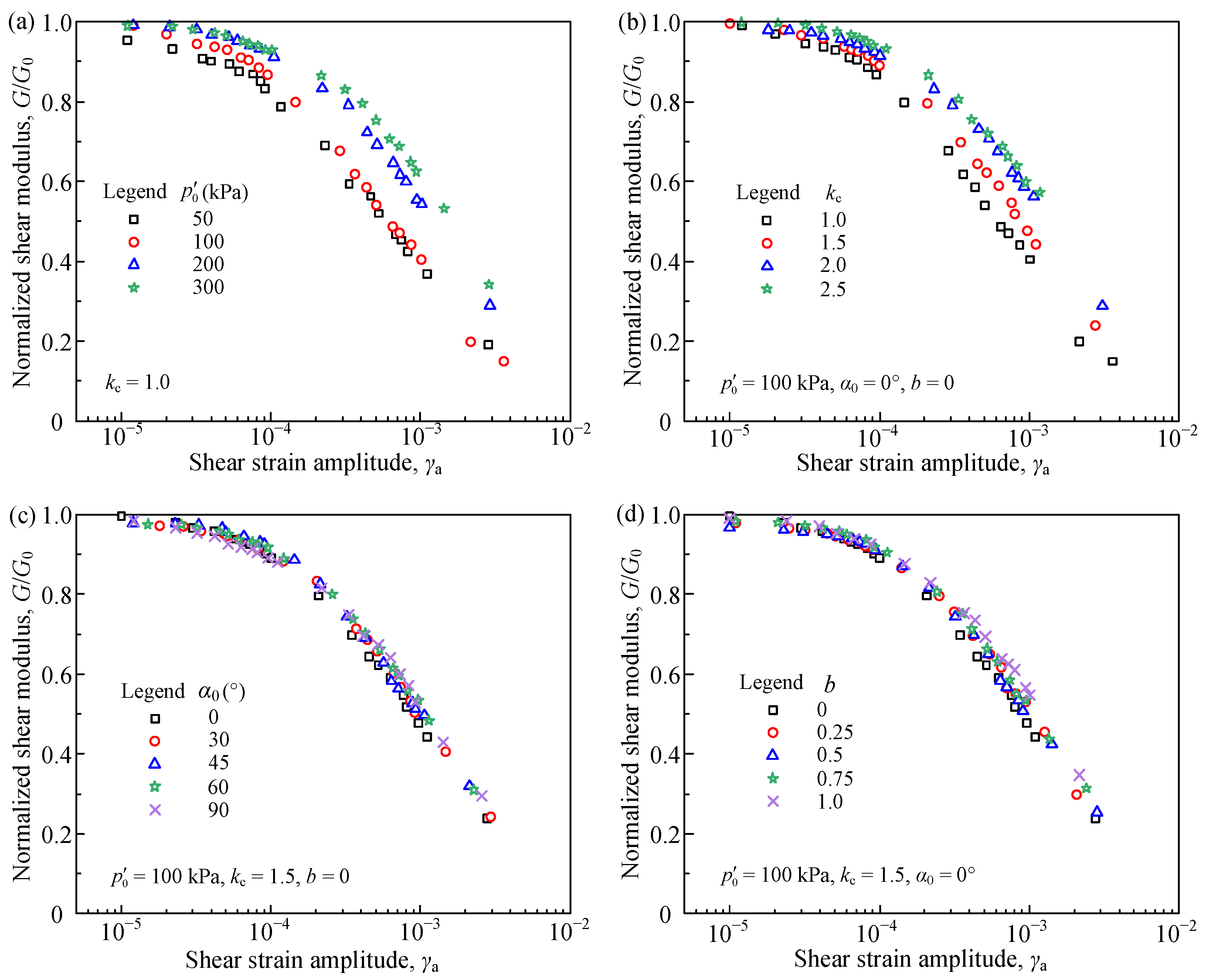
  • Shear strain modulus G decreases with the increase of γa for all tests, and the consolidation state parameters ( p 0 , kc, α0, b) have a significant effect on G. For a specified shear strain level, G generally increases with increasing p 0 and kc, but decreases with increasing α0 and b.
  • The consolidation state parameters can affect the maximum shear modulus G0 severely. Specifically, G0 has a positive correlation with p 0 and kc, and a negative correlation with α0 and b. This regulation is consistent with that of G. To further analyze the influence of consolidation state parameters on G0, a new index (μ1) that describes the complex consolidation conditions is introduced, and the four parameters λ1, λ2, λ3, λ4 in the new index are used to quantify the effect of p 0 , kc, α0, b on G0, respectively. Based on this index, a new model of G0 is established, and the test data in this study also proves the validity of this new prediction model.
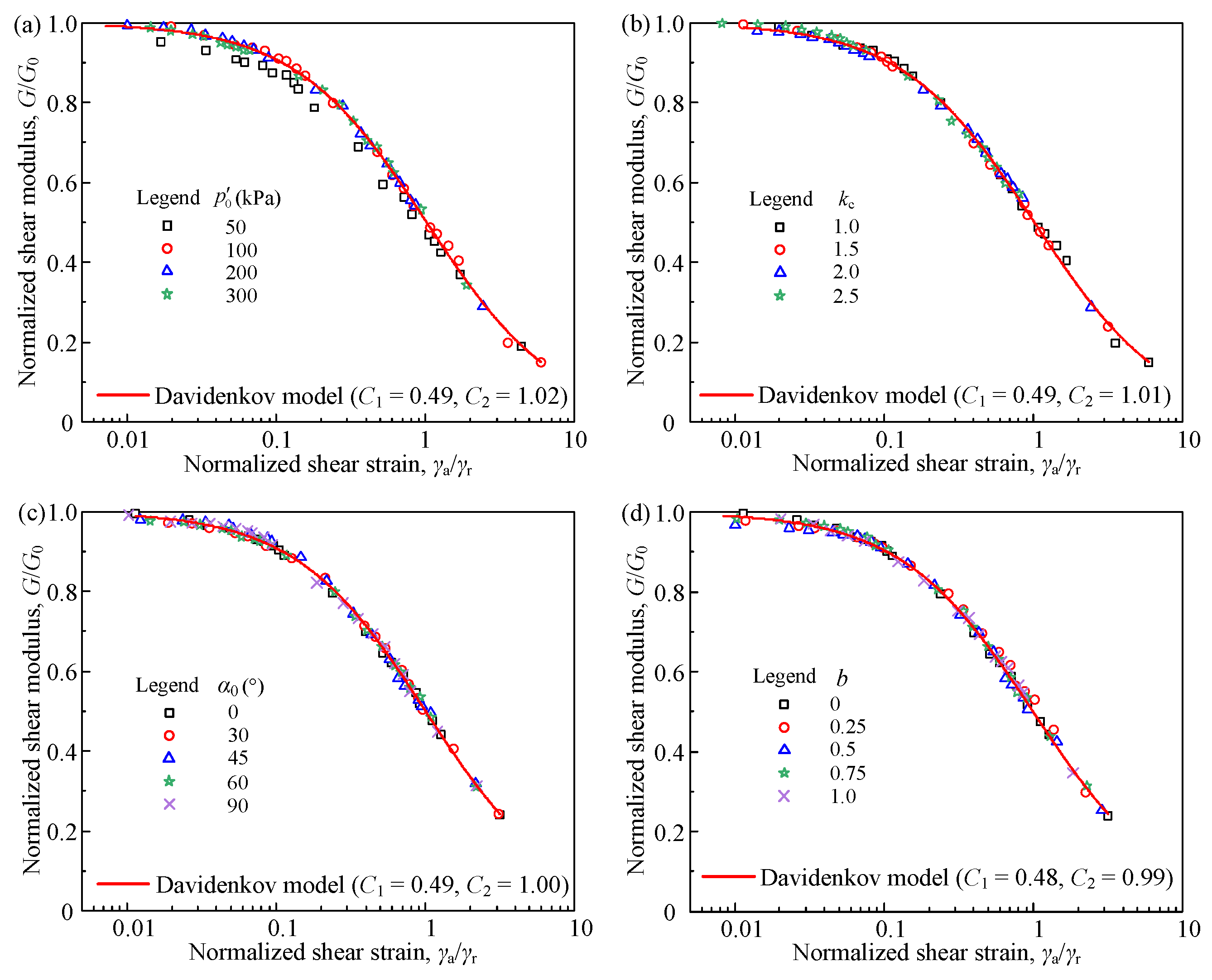
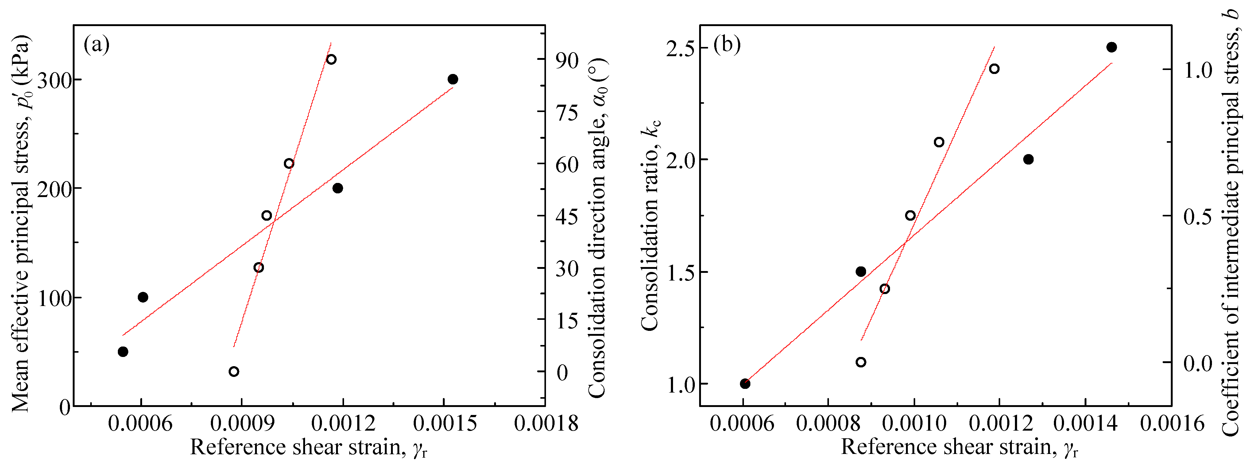
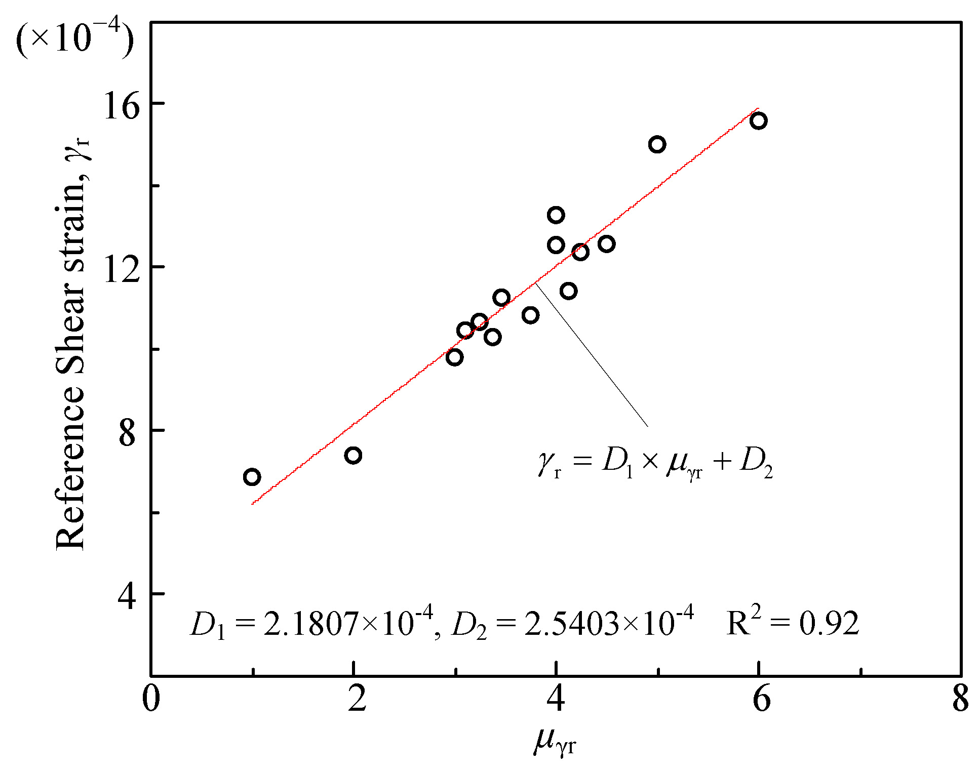
  • The reference shear strain γr under isotropic and anisotropic consolidations are also varied. Based on the parameters of λ1, λ2, λ3, λ4, another new index (μ2) is also proposed, and a strong linear relationship can be observed between γr and μ2. It is delighted to find that the relationships between normalized shear modulus G/G0 and normalized shear strain γa/γr are almost identical. The Davidenkov model can be used to describe the G/G0γa/γr curves and for simplicity, the recommended parameters of C1 and C2 in this model are 0.50 and 1.00, respectively.
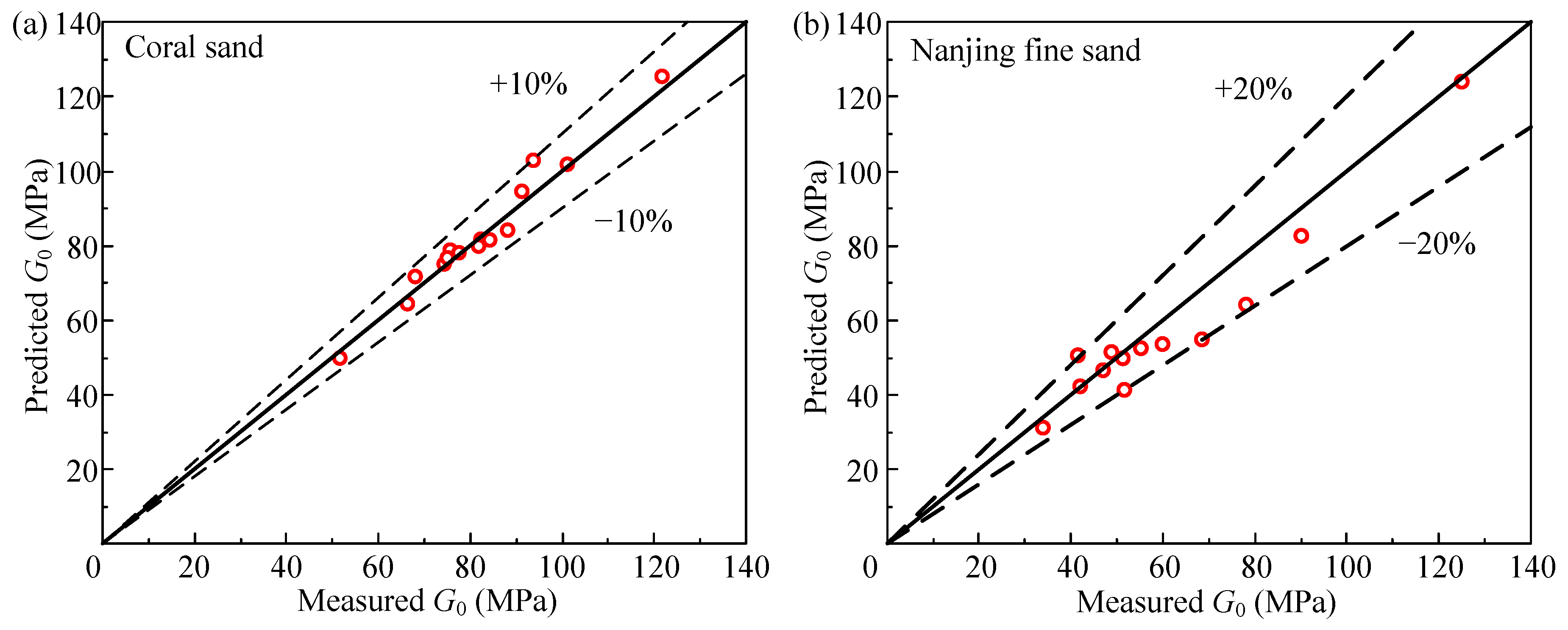
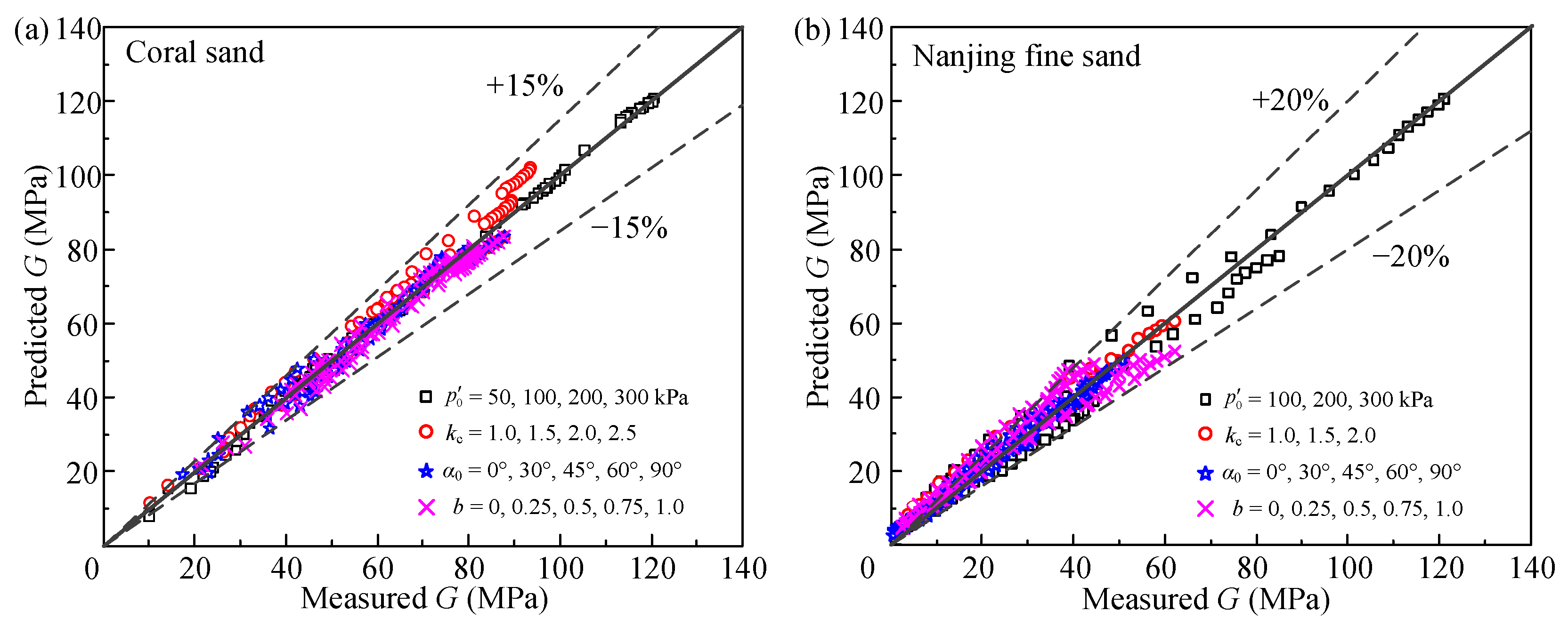
  • The prediction model proposed in this paper can well describe the dynamic shear modulus reduction trend of the tested coral sand under isotropic and anisotropic consolidation conditions, and the deviation between measured and predicted G are all within ±10%, indicating the good prediction result of this new model. However, due to the lack of test data, more test data is needed to further confirm the effectiveness of the prediction model.
  • The test data in this study can provide important parameters for island reef engineering. Correspondingly, the prediction of dynamic shear moduli with different strains can be a reference for the seismic design of the foundation. Due to the complex consolidation conditions of soils in natural environments, the prediction model of G0 proposed in this study can be a guideline in engineering practice.

Author Contributions

Conceptualization, W.M. and Q.W.; methodology, W.M.; validation, F.G.; investigation, W.M.; resources, W.M. and Q.W.; data curation, Y.Q.; writing—original draft preparation, W.M.; writing—review and editing, W.M. and Y.Q.; visualization, Y.Q.; supervision, Q.W.; funding acquisition, W.M.; All authors have read and agreed to the published version of the manuscript.

Funding

This research was funded by the National Natural Science Foundation of China (grant number: 52208350).

Institutional Review Board Statement

Not applicable.

Informed Consent Statement

Not applicable.

Data Availability Statement

The data used during the study are available from the first author by request.

Conflicts of Interest

The authors declare no conflict of interest.

References

  1. Flores Lopez, F.A.; Taboada, V.M.; Gonzalez Ramirez, Z.X.; Cruz Roque, D.; Barrera Nabor., P.; Dantal, V.S. Normalized modulus reduction and damping ratio curves for Bay of Campeche carbonate Sand. In Proceedings of the Offshore Technology Conference, Houston, TX, USA, 30 April–3 May 2018. [Google Scholar] [CrossRef]
  2. Burke, L.; Reytar, K.; Spalding, M.; Perry, A. Reefs at Risk Revisited; Report; World Resources Institute: Washington, DC, USA, 2011. [Google Scholar]
  3. Ma, W.J.; Qin, Y.; Zhao, K.; Chen, G.X. Comparisons on liquefaction behavior of saturated coral sand and quartz sand under principal stress rotation. Mar. Georesour. Geotechnol. 2022, 40, 235–247. [Google Scholar] [CrossRef]
  4. Liu, L.; Yao, X.; Ji, Z.; Gao, H.; Wang, Z.; Shen, Z. Cyclic behavior of calcareous sand from the South China Sea. J. Mar. Sci. Eng. 2021, 9, 1014. [Google Scholar] [CrossRef]
  5. Wu, Q.; Liu, Q.F.; Zhuang, H.Y.; Xu, C.S.; Chen, G.X. Experimental investigation of dynamic shear modulus of saturated marine coral sand. Ocean Eng. 2022, 264, 112412. [Google Scholar] [CrossRef]
  6. Wang, X.Z.; Wang, X.; Shen, J.H.; Ding, H.Z.; Wen, D.S.; Zhu, C.Q.; Lv, S.Z. Foundation filling performance of calcareous soil on coral reefs in the South China Sea. Appl. Ocean Res. 2022, 129, 103386. [Google Scholar] [CrossRef]
  7. Coop, M.R. The mechanics of uncemented carbonate sands. Géotechnique 1990, 40, 607–626. [Google Scholar] [CrossRef]
  8. Sharma, S.S.; Ismail, M.A. Monotonic and cyclic behavior of two calcareous soils of different origins. J. Geotech. Geoenviron. Eng. 2006, 132, 1581–1591. [Google Scholar] [CrossRef]
  9. Brandes, H.G. Simple shear behavior of calcareous and quartz sands. Geotech. Geol. Eng. 2011, 29, 113–126. [Google Scholar] [CrossRef]
  10. Salem, M.; Elmamlouk, H.; Agaiby, S. Static and cyclic behavior of North Coast calcareous sand in Egypt. Soil Dyn. Earthq. Eng. 2013, 55, 83–91. [Google Scholar] [CrossRef]
  11. Rui, S.; Guo, Z.; Si, T.; Li, Y. Effect of particle shape on the liquefaction resistance of calcareous sands. Soil Dyn. Earthq. Eng. 2020, 137, 106302. [Google Scholar] [CrossRef]
  12. Seed, H.B.; Idriss, I.M. Soil Moduli and Damping Factors for Dynamic Response Analyses; Report EERC 70-10; University of California: Berkeley, CA, USA, 1970. [Google Scholar]
  13. Kokusho, T. Cyclic triaxial test of dynamic soil properties for wide strain range. Soils Found. 1980, 20, 45–60. [Google Scholar] [CrossRef] [Green Version]
  14. Menq, F.Y. Dynamic Properties of Sandy and Gravelly Soils. Ph.D. Thesis, University of Texas at Austin, Austin, TX, USA, 2003. [Google Scholar]
  15. Wichtmann, T.; Triantafyllidis, T. Influence of the grain-size distribution curve of quartz sand on the small strain shear modulus Gmax. J. Geotech. Geoenviron. Eng. 2009, 135, 1404–1418. [Google Scholar] [CrossRef]
  16. Senetakis, K.; Anastasiadis, A.; Pitilakis, K. The small-strain shear modulus and damping ratio of quartz and volcanic sands. Geotech. Test. J. 2012, 35, 964–980. [Google Scholar] [CrossRef]
  17. Hara, A.; Ohta, T.; Niwa, M.; Tanaka, S.; Banno, T. Shear modulus and shear strength of cohesive soils. Soils Found. 1974, 14, 1–12. [Google Scholar] [CrossRef] [PubMed] [Green Version]
  18. Hardin, B.O.; Kalinski, M.E. Estimating the Shear Modulus of Gravelly Soils. J. Geotech. Geoenviron. Eng. 2005, 131, 867–875. [Google Scholar] [CrossRef]
  19. Goudarzy, M.; Rahman, M.M.; König, D.; Schanz, T. Influence of non-plastic fines content on maximum shear modulus of granular materials. Soils Found. 2016, 56, 973–983. [Google Scholar] [CrossRef]
  20. Goudarzy, M.; Rahemi, N.; Rahman, M.M.; Schanz, T. Predicting the maximum shear modulus of sands containing nonplastic fines. J. Geotech. Geoenviron. Eng. 2017, 143, 0617013. [Google Scholar] [CrossRef]
  21. Yan, K.; Wang, Y.; Yang, Z.; Lai, X.; Chen, C. Experimental study on small-strain shear modulus of unsaturated silty-fine sand. Appl. Sci. 2022, 12, 8743. [Google Scholar] [CrossRef]
  22. Iwasaki, T.; Tatsuoka, F.; Takagi, Y. Shear moduli of sands under cyclic torsional shear loading. Soils Found. 1978, 18, 39–56. [Google Scholar] [CrossRef] [Green Version]
  23. Lanzo, G.; Vucetic, M.; Doroudian, T.M. Reduction of shear modulus at small strains in simple shear. J. Geotech. Geoenviron. Eng. 1997, 123, 1035–1042. [Google Scholar] [CrossRef]
  24. Senetakis, K.; Anastasiadis, A.; Pitilakis, K. Normalized shear modulus reduction and damping ratio curves of quartz sand and rhyolitic crushed rock. Soils Found. 2013, 53, 879–893. [Google Scholar] [CrossRef] [Green Version]
  25. Chen, G.X.; Zhou, Z.L.; Pan, H.; Sun, T.; Li, X.J. The influence of undrained cyclic loading patterns and consolidation states on the deformation features of saturated fine sand over a wide strain range. Eng. Geol. 2016, 204, 77–93. [Google Scholar] [CrossRef]
  26. Saeidaskari, J.; Alibolandi, M.; Azizkandi, A.S. Undrained monotonic and cyclic behavior of Qeshm calcareous sand. Mar. Georesour. Geotechnol. 2021, 39, 798–811. [Google Scholar] [CrossRef]
  27. Wang, X.; Wang, X.Z.; Shen, J.H.; Zhu, C.Q. Particle size and confining-pressure effects of shear characteristics of coral sand: An experimental study. Bull. Eng. Geol. Environ. 2022, 81, 97. [Google Scholar] [CrossRef]
  28. Vahdani, S.; Pyke, R.; Siriprusanen, U. Liquefaction of calcareous sands and lateral spreading experienced in Guam as a result of the 1993 Guam earthquake. In Proceedings of the 5th US—Japan Workshop on Earthquake Resistant Design of Lifeline Facilities and Countermeasures against Soil Liquefaction, Snowbird, UT, USA, 29 September–29 October 1994; pp. 117–134. [Google Scholar]
  29. Chock, G.; Robertson, I.; Nicholson, P.; Brandes, H.; Medley, E.; Okubo, P.; Hirshorn, B.; Sumada, J.; Kindred, T.; Iinuma, G.; et al. Compilation of Observations of the October 15, 2006 Kiholo bay (Mw 6.7) and Mahukona (Mw 6.0) Earthquakes, Hawai’I; Report 31; Earthquake Engineering Research Institute (EERI): Oakland, CA, USA, 2006. [Google Scholar]
  30. Olson, S.M.; Green, R.A.; Lasley, S.; Martin, N.; Cox, B.R.; Rathje, E.; Bachhuber, J.; French, J. Documenting liquefaction and lateral spreading triggered by the 12 January 2010 Haiti earthquake. Earthq. Spectra 2011, 27, 93–116. [Google Scholar] [CrossRef] [Green Version]
  31. Giang, P.H.H.; Van Impe, P.O.; Van Impe, W.F.; Menge, P.; Haegeman, W. Small-strain shear modulus of calcareous sand and its dependence on particle characteristics and gradation. Soil Dyn. Earthq. Eng. 2017, 100, 371–379. [Google Scholar] [CrossRef]
  32. Chen, G.X.; Liang, K.; Zhao, K.; Yang, J. Shear modulus and damping ratio of saturated coral sand under generalised cyclic loadings. Géotechnique, 2022; ahead of print. [Google Scholar] [CrossRef]
  33. ASTM D4253-14; Standard Test Methods for Maximum Index Density and Unit Weight of Soils Using a Vibratory Table. ASTM International: West Conshohocken, PA, USA, 2006.
  34. ASTM D4254-14; Standard Test Methods for Minimum Index Density and Unit Weight of Soils and Calculation of Relative Density. ASTM International: West Conshohocken, PA, USA, 2006.
  35. ASTM D2487; Standard Practice for Classification of Soils for Engineering Purposes (Unified Soil Classification System). ASTM International: West Conshohocken, PA, USA, 2011.
  36. Zhuang, H.Y.; Wang, R.; Chen, G.X.; Miao, Y.; Zhao, K. Shear modulus reduction of saturated sand under large liquefaction-induced deformation in cyclic torsional shear tests. Eng. Geol. 2018, 240, 110–122. [Google Scholar] [CrossRef]
  37. Chen, G.X.; Ma, W.J.; Qin, Y.; Zhao, K.; Yang, J. Liquefaction susceptibility of saturated coral sand subjected to various patterns of principal stress rotation. J. Geotech. Geoenviron. Eng. 2021, 147, 04021093. [Google Scholar] [CrossRef]
  38. Sze, H.Y.; Yang, J. Failure modes of sand in undrained cyclic loading: Impact of sample preparation. J. Geotech. Geoenviron. Eng. 2014, 140, 152–169. [Google Scholar] [CrossRef]
  39. Huang, A.B.; Chang, W.J.; Hsu, H.H.; Huang, Y.J. A mist pluviation method for reconstituting silty sand specimens. Eng. Geol. 2015, 188, 1–9. [Google Scholar] [CrossRef]
  40. ASTM D5311D/5311M; Standard Test Method for Load Controlled Cyclic Triaxial Strength of Soil. ASTM International: West Conshohocken, PA, USA, 2013.
  41. Chen, G.X.; Zhou, Z.L.; Sun, T.; Wu, Q.; Xu, L.Y.; Sara, K.; Ling, D.S. Shear modulus and damping ratio of sand-gravel mixtures over a wide strain range. J. Earthq. Eng. 2019, 23, 1407–1440. [Google Scholar] [CrossRef]
  42. Kumar, S.S.; Krishna, A.M.; Dey, A. Evaluation of dynamic properties of sandy soil at high cyclic strains. Soil Dyn. Earthq. Eng. 2017, 99, 157–167. [Google Scholar] [CrossRef]
  43. Ghayoomi, M.; Suprunenko, G.; Mirshekari, M. Cyclic triaxial test to measure strain-dependent shear modulus of unsaturated sand. Int. J. Geomech. 2017, 17, 04017043. [Google Scholar] [CrossRef] [Green Version]
  44. Wu, Q.; Hang, T.Z.; Zhao, K.; Chen, G.X. Reduction of dynamic shear modulus of saturated marine sandy silt under complex stress conditions. Mar. Georesour. Geotech. 2022. [Google Scholar] [CrossRef]
  45. Seed, H.B.; Wong, R.T.; Idriss, I.M.; Tokimatsu, K. Moduli and damping factors for dynamic analyses of cohesionless soils. J. Geotech. Eng. 1986, 112, 1016–1032. [Google Scholar] [CrossRef]
  46. Yuan, X.M.; Sun, J.; Sun, R. Effect of Consolidation Ratios on Maximum Dynamic Shear Modulus of Sands. Earthq. Eng. Eng. Vib. 2005, 4, 59–68. [Google Scholar]
  47. Sun, J.; Gong, M.S.; Tao, X.X. Dynamic shear modulus of undisturbed soil under different consolidation ratios and its effects on surface ground motion. Earthq. Eng. Eng. Vib. 2013, 12, 561–568. [Google Scholar] [CrossRef]
  48. Hardin, B.O.; Drnevich, V. Shear modulus and damping in soils. J. Soil Mech. Found. Div. 1972, 97, 667–692. [Google Scholar] [CrossRef]
  49. Yuan, X.M.; Sun, R.; Sun, J.; Meng, S.J.; Shi, Z.J. Laboratory experimental study on dynamic shear modulus ratio and damping ratio of soils. Earthq. Eng. Eng. Vib. 2000, 20, 133–139. [Google Scholar] [CrossRef]
  50. Oztoprak, S.; Bolton, M.D. Stiffness of sands through a laboratory test database. Geotechnique 2013, 63, 54–70. [Google Scholar] [CrossRef]
  51. Martin, P.P.; Seed, H.B. One-dimensional dynamic ground response analyses. J. Geotech. Eng. Div. 1982, 108, 935–952. [Google Scholar] [CrossRef]
Figure 1. Particle distribution curve, photograph and scanning electron microscope picture (SEM) of tested coral sand.
Jmse 11 00214 g001
Figure 2. Hollow cylinder apparatus and illustrative stress state in a hollow cylindrical specimen subjected to axial load W, torque MT, inner pressure pi, and outer pressure po: (a) applied loads, (b) stress components, (c) principal stress components, and (d) major, intermediate, minor principal stress.
Jmse 11 00214 g002
Figure 3. Consolidation stress paths.
Jmse 11 00214 g003
Figure 4. Typical test results of strain-controlled undrained cyclic torsional shear: (a) EPWP (ue), (b) shear strain (γ), (c) torsional shear stress (τ) along with stage number (N); (d) stress-strain relationship of whole test period and single step.
Jmse 11 00214 g004
Figure 5. The idealized shear stress-strain response of soil under cyclic loading.
Jmse 11 00214 g005
Figure 6. G versus γa curves of isotropically and anisotropically consolidated saturated coral sand for the undrained cyclic torsional shear tests under various (a) effective mean principal stress, (b) consolidation ratio, (c) consolidation direction angle, and (d) coefficient of intermediate principal stress.
Jmse 11 00214 g006
Figure 7. The correlations between the experimental G0 and various consolidation parameters under various (a) effective mean principal stress and consolidation direction angle, (b) consolidation ratio and coefficient of intermediate principal stress.
Jmse 11 00214 g007
Figure 8. The correlation between the experimental G0 versus μG0.
Jmse 11 00214 g008
Figure 9. The comparison between the experimental G0 versus predicted G0 of (a) coral sand and (b) Nanjing fine sand under various consolidation conditions.
Jmse 11 00214 g009
Figure 10. G0 versus γa curves of isotropically and anisotropically consolidated saturated coral sand for the undrained cyclic torsional shear tests under various (a) effective mean principal stress, (b) consolidation ratio, (c) consolidation direction angle, and (d) coefficient of intermediate principal stress.
Jmse 11 00214 g010
Figure 11. Shear modulus reduction curves of saturated coral sand under various consolidation conditions [12,13,49,50].
Jmse 11 00214 g011
Figure 12. G/G0 versus γa/γr curves of isotropically and anisotropically consolidated saturated coral sand for the undrained cyclic torsional shear tests under various (a) effective mean principal stress, (b) consolidation ratio, (c) consolidation direction angle, and (d) coefficient of intermediate principal stress.
Jmse 11 00214 g012
Figure 13. The correlation between γr and stress characteristic parameters of (a) effective mean principal stress and consolidation direction angle, (b) consolidation ratio and coefficient of intermediate principal stress.
Jmse 11 00214 g013
Figure 14. The correlation between reference shear strain γr and μγr.
Jmse 11 00214 g014
Figure 15. The correlation between the experimental G versus predicted G of (a) coral sand and (b) Nanjing fine sand under various consolidation conditions.
Jmse 11 00214 g015
Table 1. Performance indexes of the apparatus used in this study.
ControllerCapacityDeviationPrecision
Axial load3 kN0.1% F.S3 N
Axial displacement±40 mm0.1% F.S1 μm
Torque30 Nm0.1% F.S0.03 Nm
Rotation displacement360°0.057% F.S0.04°
Axial/Rotation frequency≤5 Hz--
Outer/inner cell pressure1 MPa0.1% F.S1 kPa
Outer/inner cell volume200 mL0.25% F.S0.001 mL
Back pressure1 MPa0.1% F.S1 kPa
Back volume200 mL0.1% F.S0.001 mL
Pore pressure1 MPa0.1% F.S1 kPa
F.S = full scale.
Table 2. Equations for data interpretation.
Stress ComponentPrincipal StressStress Characteristic Parameter
Vertical
σ z = W π ( r o 2 r i 2 ) + p o r o 2 p i r i 2 ( r o 2 r i 2 )
Major
σ 1 = σ z + σ θ 2 + ( σ z σ θ 2 ) 2 + τ z θ 2
Mean principal stress
p = σ 1 + σ 2 + σ 3 3
Radial
σ r = p o r o + p i r i r o + r i
Intermediate principal
σ 2 = σ r
Ratio of major and minor principal stress
k c = σ 1 / σ 3
Circumferential
σ θ = p o r o p i r i r o r i
Minor principal
σ 3 = σ z + σ θ 2 ( σ z σ θ 2 ) 2 + τ z θ 2
Coefficient of intermediate principal stress
b = ( σ 2 σ 3 ) / ( σ 1 σ 3 )
Shear
τ z θ = 3 M T 2 π ( r o 3 r i 3 )
Direction angle of principal stress
α = 1 2 arctan ( 2 τ z θ σ z σ θ )
Table 3. Scheme of multi-stage strain-controlled undrained cyclic shear tests.
Test No.End of ConsolidationSoil PropertyTest ResultFitting Parameter
p 0 (kPa) kcαc/(°)bDrc (%)eG0 (MPa)γr (×10−4)C1C2
01501.0--49.181.36151.65.4640.460.92
02100 49.451.35968.16.0560.480.98
03200 51.641.343101.111.8440.481.02
04300 52.471.337121.715.2640.481.01
051001.50050.961.34888.18.7580.520.98
06 2.0 51.511.34491.212.6710.521.00
07 2.5 52.881.33493.714.6130.521.01
081001.530 51.371.34582.39.4970.491.01
09 45 51.781.34275.69.7310.521.04
10 60 51.641.34374.310.3960.501.04
11 90 51.511.34466.311.6500.501.00
121001.500.2551.781.34284.29.3150.471.02
13 0.5051.371.34581.89.9130.520.98
14 0.7551.641.34377.510.5820.491.05
15 1.0051.371.34575.211.8740.500.96
Disclaimer/Publisher’s Note: The statements, opinions and data contained in all publications are solely those of the individual author(s) and contributor(s) and not of MDPI and/or the editor(s). MDPI and/or the editor(s) disclaim responsibility for any injury to people or property resulting from any ideas, methods, instructions or products referred to in the content.

