Article

Development and Validation of Heat Release Characteristics Identification Method of Diesel Engine under Operating Conditions

by
Sergejus Lebedevas
1,*,
Justas Žaglinskis
2 and
Martynas Drazdauskas
1
1
Faculty of Marine Technology and Natural Sciences, Klaipeda University, Bijūnų str. 17, 91225 Klaipėda, Lithuania
2
Lithuanian Maritime Academy, I. Kanto 7, 92123 Klaipeda, Lithuania
*
Author to whom correspondence should be addressed.
J. Mar. Sci. Eng. 2023, 11(1), 182; https://doi.org/10.3390/jmse11010182
Submission received: 19 December 2022 / Revised: 6 January 2023 / Accepted: 8 January 2023 / Published: 11 January 2023
(This article belongs to the Special Issue Decarbonization of Ship Power Plants)

Abstract

:
The decarbonisation of maritime transport in connection with the European Union and International Maritime Organisation directives is mainly associated with renewable and low-carbon fuel use. For optimisation of energy indicators of ship power plants in operation on renewable and low-carbon fuel, it is rational to use numerical research methods. The purpose of this research is to devise methodological solutions for determining the heat release characteristics, m and φz parameters of Wiebe model that can be applied to mathematical models of diesel engines under operating conditions. Innovative solutions are proposed, which in contrast with the methods used in practice, are not related to experimental registration of combustion cycle parameters. These registration techniques were replaced by the proposed exhaust gas temperature or exhaust manifold surface temperature registration method. The acceptable accuracy of results validates the methodological solutions for solving practical tasks: according to the Wiebe model, the error of determining m and φz compared with experimental data does not exceed 3–4%. The proposed method was implemented by simulating the energy indicators of two diesel engines, car engine 1Z 1.9 TDI (Pe = 66 kW; n = 4000 RPM) and multipurpose 8V396TC4 (Pe = 380–600 kW; n = 1850 RPM), in a single-zone model. The variation in experimental data when the engines operated on both diesel and rapeseed methyl ester (a biodiesel fuel), was approximately 1%. The authors anticipate further development of completed solutions with their direct application to ship power plants in real operating conditions.

1. Introduction

The decarbonisation of maritime transport has become one of the strategic development directions in EU maritime industry because its CO2 emission reaches 11% of the total CO2 discharged by the European transport sector [1]. According to EU strategic development plans it is necessary to achieve greenhouse gas (GHG) emissions reduction of international shipping by up to 90% by the year 2050 [1]. Fundamentally such plans are associated with the use of renewable and low-carbon fuels [2] in combination with innovative technologies and solutions of fuel injection systems [3] and combustion execution [4] which improves emissions, fuel economy, efficiency and engine performance. In the near-term perspective, according to 2009/16/EC EU directive [5,6], the aim is to increase the production and the uptake of sustainable renewable and low-carbon fuels for maritime transport sector. The share of biofuels and biogas in the total balance of renewable and low-carbon fuels until 2030 will take 6–9% and 87–89.5% by 2050 [5,6]. Evidently, such plans were adopted due to favourable technical possibilities of transferring diesel power plants to operate on biofuels.
Analytical assessments indicate that even with the operation of ship power plants using renewable and low-carbon fuels (i.e., biodiesel, bio-LNG, and bio-ethanol, which are derived from non-food plant biomass according to the 2009/16/EC EU directive [5,6]), attaining the 7.5% target GHG emission reduction in maritime transport is problematic in the first phase until 2030. In the first place, this requires retrofitting the operational fleet power plants to run on renewable and low-carbon fuels. Recent reports show that on average, every year, 79% of new ships are built to operate on traditional fuel, and 98.4% of operating fleet power plants use petroleum fuel [7,8]. Moreover, the average long operational age of ships reaches 21.1 and 28.6 years in economically developed and developing countries, respectively [9]. These facts further prove that one of the ways towards the decarbonisation of maritime transport sector is retrofitting of wide range operational diesel ship power plants to run on renewable and low-carbon fuels (i.e., biodiesel). Considering the wide variety of diesel engine types and models for ship power plants and to reduce time and financial costs, retrofitting using complex numerical and experimental research-based technological solutions can be rationally justified. In addition, application of numerical methods to investigate the use of renewable and low-carbon fuels in real operating power plant conditions is appropriate for the following reasons. During operation, engines technical condition often changes quite significantly compared to manufacturer specification. Therefore, when evaluating energy indicators of the engine and ways to improve them using new types of fuel, it is necessary to refer to its actual technical condition. In addition, due to already mentioned long operational age of ships, the production of many engine models ends and their tests at the manufacturer are associated with technical difficulties. Therefore, research under real operating conditions should be considered as most technically acceptable.
Engine retrofitting by numerical methods to enable operation with other types of fuel is fundamentally related to combustion cycle research and optimisation. Such studies are alternatively implemented using single-zone IMPULS, AVL BOOST [10,11], or multi-zone mathematical models (MMs) (e.g., AVL FIRE [12], KIVA [13], and VECTIS [14]). The practical advantage of multi-zone MMs is the considerable potential of investigating the physical processes of energy transformation and formation of harmful components in engine cylinder, including fuel injection chemical kinetics, evaporation, formation of active radicals, and combustion. However, matching the calculated parameters of multi-zone MMs with those of operating engine models is an extremely difficult task because the combustion cycle parameters must be known. In particular, these parameters may be required at the initial stage of research for modelling the parameters of an operational engine model. Typically, initial data, which are necessary for modelling ship power plant parameters (especially the operational model) to implement the parameters of the MM combustion cycle adequately, are lacking. Note that the adequacy of the MM process considerably depends on such data [15]. The absence of these data leads to the utilisation of simplified single-zone models in the initial research stage because these models are more convenient in practical use. Single-zone models simulate operational engine energy parameters according to the energy balance principle when the characteristics of air supply units, injection devices, etc. are evaluated, i.e., simulation of engine energy indicators is carried out as for a single technological object under certain operating conditions. The application of single-zone models especially at the initial stage of research to evaluate engine energy efficiency indicators is rational. Furthermore, they enable the evaluation of CO2 emissions and identify means to reduce them because such emissions are determined by fuel elemental chemical composition and consumption. Typically, experimental studies of multi-zone MMs are applied to subsequent research stages to describe the physical process characteristics occurring in the cylinder in detail [16].
In view of the limited availability of operational fleet engine parameters and significant change in engine reference indicators in connection with the influence of operating conditions and their preparation, the use of single-zone MMs (e.g., AVL BOOST and IMPULS) for simulation is rational. The efficiency of using single-zone MMs is governed by the adequate determination of heat release characteristic parameters based on experimental data or analytical dependencies (AVL BOOST [11] and IMPULS [10]). Single-zone MMs are most practically applied to the Wiebe heat release characteristic model, which is based on the law of fuel combustion kinetics [17]. The simplicity and sufficient accuracy of the Wiebe model for solving practical problems ensure its use in conjunction with modern multi-zone models and development of modified model forms [18,19,20,21,22,23]. The analytical form of the Wiebe single-phase combustion model is characterised by two indicators: m (form factor that determines the location of maximum heat release rate) and φz (conditional heat release duration). These parameters determine the heat release characteristic for a specific engine load mode and are used to evaluate combustion cycle energy efficiency indicators. However, the application of the method to a wide range of engine load regimes is complicated because parameter refinement is required for each case. Accordingly, the analytical solutions formulated by Woschni were extended to the Wiebe model [24,25,26]. With the parameters of heat release characteristic derived from engine experimental data in rated power mode, the use of Woschni’s relative m and φz change expressions determines the absolute values of these parameters for engine part load modes. These parameters provide opportunities for optimising control and certain design parameters to evaluate the energy efficiency of renewable and low-carbon fuels.
The Wiebe model was proposed in 1970 [17] to determine the heat release using single-phase (kinetic) combustion and double-phase (kinetic–diffusion) combustion functions with various types of fuel. The model continues to be widely used in internal combustion engine (ICE) research [21,22,23,27,28,29,30,31,32,33]. In the initial research stage, virtually all the Wiebe heat release characteristic parameters are determined according to experimental indicator diagrams with the engine operating in rated power and part load modes. The use of this model for a broad range of engines [27] at the rated power mode reveals the model’s wide application potential. It can be applied to different types of engines and fuels: MWM D229-4 (B/S 102/120 mm; 49 kW; 1800 RPM) diesel engine running on ethanol; Fiat Fire 1.0 (B/S 70/65 mm; 56 kW; 1400 RPM) spark ignition engine running on 92.5% ethanol and 7.5% hydrogen; and Scania DC-12 (B/S 127/154 mm; 295 kW; 1800 RPM) diesel engine running on natural gas. The calculation errors of engine energy parameters compared with the experimental data do not exceed 2–3%. However, in applying the Wiebe single-phase combustion function to a wide range of engine loads, an increase in errors was observed, especially in part load modes. The authors reached a similar conclusion in their research on diesel engines (single cylinder; B/S 170/195 mm) [28] at 50% and 25% engine loads. Combustion cycle parameters were determined by applying the logarithmic anamorphosis method to each load mode based on indicator diagrams. High approximation coefficient (R2) values were obtained: 0.995 and 0.964 for 50% and 25% engine loads, respectively. The application of the single-phase function at 50% and especially at 25% engine loads does not fully reveal the combustion cycle heat release characteristics. Accordingly, the use of a double-phase Wiebe function for a more accurate assessment is suggested. The foregoing is supported by the work of other authors on the single-phase Wiebe function for an engine (TBD234V6 medium speed; B/S 128/140 mm; 444 kW) operating on 70% diesel and 30% fatty acid methyl ester (D70B30) at a 50% and 25% engine load. In all cases, the results led to unacceptable inaccuracy (R2 = 0.94) compared with experimental data [29]. In contrast, according to several other researchers the use of the single-phase combustion Wiebe function with Woschni’s analytical additions ensure an adequately accurate determination of m and φz parameters over a wide load range. With this methodology, the authors [30] present a comparison of marine diesel engine (7-cylinder two-stroke MAN B&W 7K98MC; B/S 980/2660 mm; 40 100 kW; 94 RPM) energy indicators at 25–100% engine load modes. These numerical study results of energy parameters were validated by experimental data when the engine was running on diesel. In all cases considered, the errors did not exceed 1.16%, further demonstrating the wide application range of the Wiebe single-phase combustion function with Woschni’s analytical additions.
The results of applying the single-phase Wiebe function to engines running on biodiesel are sometimes contradictory. This contradiction is similar to that observed when diesel is used. In the investigation of the influence of biodiesel on combustion cycle parameters [19,31], this function does not accurately reproduce the heat release characteristic based on experimental cylinder pressure data in a wide range of engine loads. The diesel engine combustion cycle is determined by kinetic and diffusion phases. Therefore, when the engine is operated in a low-load mode, a double-phase combustion Wiebe function is more accurate. Reports in literature show that the calculation error of the combustion cycle energy parameters resulting from the use of the double-phase Wiebe function compared with experimental data reaches 4.15% for an engine (Deutz FL1 906; B/S 95/100 mm single cylinder; 11 kW; 2400 RPM) running on D70/B30 at different load modes [31]. On the contrary, in a study [29] considering an analogous load range (25–100%), a high simulation accuracy of energy parameters of an engine (TBD234V6 medium speed; B/S 128/140 mm; 444 kW) was achieved with an error of 0.06–1.2%. Moreover, in applying the double-phase Wiebe function to simulate a marine engine running on diesel (B/S 128/140 mm; 444 kW; 1800 RPM), the calculation error of the heat release characteristic at a 20% engine load reaches 1.4% [22]. The double-phase Wiebe function method can also be effectively applied to a diesel engine operating on dual diesel–biogas and diesel–natural gas fuels. In both cases [32], the double-phase Wiebe function was employed to create a zero-dimensional MM when the load of the engine (Lister Petter single cylinder; 4 stroke; 4.5 kW; 1500 RPM) was 20–100%, as validated by engine bench tests. Engine energy parameters were assessed by recalculating m and φz for each load mode according to indicator diagrams, and the average error was 3%. In [33], the authors converted a diesel engine to operate on dimethyl ether. The results of applying the double-phase Wiebe function (parameters were derived from experimental indicator diagrams) to an engine (B/S 92/96 mm; 15,6 kW; 2600 RPM) are satisfactorily compatible with experimental data. Overall, the error in the 50–100% load range reaches 1.2%.
In all cases, the single-phase Wiebe combustion model, widely used in heat release characteristic studies, is unable to simulate the combustion cycle accurately compared with experimental data. In modern engine research, over a wide range of engine loads and especially when renewable and low-carbon fuels are used, the two-phase Wiebe combustion model achieves more accurate results. However, this model is more complicated to apply compared with the single-phase model. Moreover, it has no analogous application to part load modes using Woschni’s analytical solutions. The implementation of low dynamics of combustion cycle on fourth-generation engine models [34,35] and on modern engines [36] (by increasing the degree of compression and intensity of fuel injection, delaying the phase of fuel supply to the cylinder, etc.), to limit emissions of nitrogen oxides, basically initiates a diffusion combustion process, which correlates quite accurately with the single-phase Wiebe model. This factor is also typical for medium and low-speed marine diesel engines. Accordingly, based on the reports in literature, the single-phase Wiebe combustion model with Woschni’s analytical solutions in a single-zone MM has a good agreement with experimental data when simulating the energy parameters of diesel engines over a wide load range for engines running on diesel and renewable fuels. Therefore, the use of this model at the initial research stage is more rational.
For practical applications, determining m and φz parameters is extremely important under various engine operating conditions. In general, these parameters are determined based on experimental data when the pressure in the cylinder is registered (i.e., when registering indicator diagrams) [27,28,29,30,31,32,33]. According to ongoing research, no technological difficulties are encountered in performing engine bench tests under laboratory conditions to record the pressure in the cylinder and other operating parameters. However, with respect to engine in operation, the implementation of engine tests under operating conditions to record indicator diagrams is physically impossible, except with high-power models. Indeed, in most cases, recording indicator diagrams is technically impossible. Therefore, when the amount of data is limited and engine combustion cycle parameters are not recorded, a simplified approach (i.e., the analytical–graphical Bulaty–Glanzman method) is used [37]. In this method, the registration of experimental indicator diagrams is not necessary. Hence, the technique is convenient to use. Nevertheless, its original version is anticipated to intervene in the engine structure when registering the maximum combustion cycle pressure. This means that its use under operational conditions without modification is also complicated primarily for a class of high-speed engines that are almost exclusively used in tugboats and liner shipping auxiliary power plants.
After transport decarbonisation problems analysis, it can be stated that calculation methods based on Wiebe’s heat release model remain relevant for various fuels. Both classic single-phase and double-phase function modifications are used in practice. For modern diesel engines with relatively low combustion cycle dynamics, the single-phase combustion model provides acceptable simulation accuracy under various operating loads. However, in a broader practical context, a modification of the two-phase model is more universal. In both cases, the heat release characteristics are determined based on analysis of experimentally recorded combustion cycle indicator diagrams. This does not cause technological difficulties under engine test bench and engine research conditions. In contrast, under real engine operating conditions in a facility, it becomes difficult to determine the heat release characteristic in many cases. The correct interpretation of research results and decision making depend on the correct description of the task in the process of mathematical modelling. Therefore, to solve maritime transport decarbonisation problems, especially concerning engines under operation, it is rational to create numerical-experimental tools to determine the actual combustion cycle indicators in the main operating load modes.
The main objective and novelty of the research was the creation of methodological tools to determine heat release characteristic parameters of diesel engine under operating conditions. As a mathematical basis for the planned development, it is advisable to use alternatively both Wiebe combustion models: single-phase at the initial stage of research. Research tasks included several alternative development options with the use of a single-zone mathematical model for engine energy indicators simulation depending on the availability of registration parameters.

2. Materials and Methods

Methodological solutions are based on the results of the experimental and numerical studies conducted by the authors on the operational parameters of diesel engines, shifting from the use of petroleum to renewable fuels and their mixtures (e.g., rapeseed methyl ester (RME), Camelina sativa methyl ester, butanol, agricultural industrial waste, and microalgae) [38,39,40,41,42,43,44]. By studying combustion cycle parameters using the single-zone MM of engines running on liquid low-carbon biofuels, the practical implementation efficiency of the Wiebe function with Woschni’s analytical additions was verified. These verified results are the basis for expanding the determination of Wiebe m and φz heat release characteristic parameters using the Bulaty–Glanzman method with the aim of using them for engine testing under operating conditions.

2.1. Experimental Research

The main scope of experimental research presented in this article is implemented on an 1Z engine with turbocharged direct injection (TDI). In order to ensure the controllability of combustion cycle boundary conditions (air pressure, Pk, and temperature, Tk), the exhaust gas recirculation system was disabled during the tests. To extend the prepared methodology solutions to different types of diesel engines, the methodology was also applied to a multi-purpose high-speed transport diesel engine (8V396TC4). The main engine parameters are summarised in Table 1.
High-speed diesel engines were selected as research subjects due to several reasons. Most of low and medium speed power plants in liner shipping industry are equipped with combustion cycle performance monitoring systems. Therefore, determining heat release characteristic based on analysis of experimental indicator diagrams does not cause difficulties. The opposite situation is typical for high-speed auxiliary diesel engines as well as for different type of in harbour operated vessels, mainly tugboats. The decarbonisation of tugboats is equally important as the share of air pollution in the harbour area and adjacent agglomerations reaches 14–19% [45]. The explanation is related to the wide range of high-speed engine models of different technical level and age existing in operating tugboats fleet. For example, about 120 different tugboats operate in the main harbors of Baltic Sea, almost half of which are between 21 and 50 years old. Among the engines installed in tugboats a significant number of them are models of the “396” series, similar to the selected object of this research.
In order to achieve the research objective, methodological aspects are emphasised in the implementation of numerical research. The experimental test results of engines and manufacturer specifications of energy parameters are used to verify the developed methodology. To describe the experimental section of the study, the engine test bench structure and test equipment including their characteristics are detailed in the previous publications of the authors [46,47].

2.2. Experimental Research Setup

A brake stand KI-5543 was used to calculate engine load and determine crankshaft speed with a torque measurement error of ±1.23 Nm and a speed error of 1%. Diesel consumption was measured with a scale SK-5000 and a stopwatch, the measurement accuracy is 0.5%. The cylinder pressure was measured with a piezoelectric sensor AVL GH13P (with a sensitivity of 16 ± 0.09 pC/bar) built into the glow plug pocket. Pressure measurements were recorded at a frequency of 100 cycles using an AVL DiTEST DPM 800 oscilloscope with 1% measurement accuracy, with data displayed and recorded in LabView Real software. The intake air flow into the engine manifold was measured with a BOSCH HFM 5 air flow meter with a measurement accuracy of 2%. The air pressure in the engine intake manifold was measured by a Delta OHM HD 2304.0 air pressure gauge, with a measurement error of ±0.0002 MPa for the TP704-2BAI sensor. Temperatures of exhaust gases, intake air, and water entering the engine were measured by K-type thermocouples with an accuracy of ±1.5 °C. The injection timing was controlled using a modulation PWM (pulse width modulation) algorithm, and the signal generator was controlled by a pulse controller TMW1. This device was connected directly to the fuel pump and disconnected from the engine electronic control unit.
Measurements of engine operating in a specific load mode were performed 5–10 times with further data analysis using statistical mathematical methods. Calculations for estimating errors of indirect parameters are also determined based on principles of mathematical statistics with an accuracy of ±1.5% according to general form expression:
δ y = ( δ x 1 ) 2 + ( δ x 2 ) 2 + ( δ x n ) 2
where δ y is relative error of function y (%); δ x 1 δ x n are relative errors of analytic dependence arguments (%).

2.3. Fuel Specifications

Based on the research objectives related to the conversion of marine diesel engines in operational fleets to run on renewable and low-carbon fuels, two types of fuel were used in the experiment: standard diesel fuel (based on EN 590) and commonly used fuel, B30 (a mixture of 30% RME and 70% diesel fuel), see Table 2.

2.4. Numerical Study of Engine Performance Using MM

A single-zone MM implemented in IMPULS software was used in numerical studies. The software was developed at St. Petersburg Central Diesel Research Institute [10] and used by one of the authors for developing and modifying high-speed transport engines (e.g., B/S 15/15, 15/18, and 16.5/18) [49,50,51]. Regarding the methodological solutions for engines with energy-efficient operations described in this study, the software’s implementation (different from multi-zone MMs (e.g., AVL FIRE) [12]) of the law of closed free energy cycle for engines with different types of air supply systems (e.g., free, compressor-driven, and multi-stage systems) is fundamental. The algorithm is based on quasi-static equations of thermodynamics and gas dynamics considering exhaust system design parameters, turbine and compressor variable efficiency coefficients, heat loss to engine cooling system, and ambient air parameters. The processes occurring in the cylinder are described by a system of differential equations consisting of Equation (2) energy and Equation (3) mass laws as well as Equation (4) state equations, as follows:
d U d τ = d Q r e d τ d Q e d τ P · d V d τ + h s · d m s d τ h e x · d m e x d τ
d m d τ = d m s d τ + d m i n j d τ d m e x d τ
d P d τ = m · R V · d T d τ + m · T V · d R d τ + R · T V · d m d τ P V · d V d τ
where U is the internal energy (J); Qre and Qex are the heat release and heat exchange energies (J), respectively; P is the pressure (Pa); V is the volume (m3); hs is the supply working body enthalpy (J/kg); hex is the exhaust working body enthalpy (J/kg); m is the total mass (kg); ms is the supply air mass (kg); minj is the injected fuel mass (kg); mex is the exhaust gas mass (kg); τ is the time (s); R is the gas constant (J/kg·K); and T is the temperature (K).
In order to achieve the purpose of this study, the software was supplemented with models for calculating the different chemical composition of fuels. Most of the phenomenological sub-models implemented in the software are similar to those implemented in the well-known AVL BOOST software [11,52]. One of the heat release characteristic refinement forms used in this study is a Wiebe model [17] with Woschni analytical additions [25,26,46] (used for modelling engine parameters in part load modes). This approach is widely used in combustion cycle modelling studies [15,30].
The rate of heat release according to the Wiebe model [6] was determined using the following equation:
d x d ( φ φ z ) = C ( m + 1 ) ( φ φ z ) m · e C ( φ φ z ) m + 1
d x = d Q Q
In the foregoing, Q describes the total heat release when burned in the cylinder; φ is the heat release duration; C is a function parameter (equal to 6.9 in the case of complete combustion); m is the heat release form factor; and x is the amount of heat released.
The amount of heat released starting from combustion is assessed using the following equation:
x = 1 e C ( φ φ z ) m + 1
The Woschni analytical solutions are dedicated to the Wiebe heat release model parameters (m (form factor) and φz (heat release duration)) that are recalculated from model calibration mode to engine part load modes when environmental conditions, design and regulation parameters, and other influencing factors change [26].
m i   m 0 = ( φ τ i 0 φ τ i ) a 2 · P k i · T k 0 P k 0 · T k i · ( n 0 n i ) a 1
φ z i φ z 0 = ( λ 0 λ i ) a 3 · ( n i n 0 ) a 4
In the foregoing, a1, a2, a3, and a4 are constant coefficients; TK0 and TKi are charge air temperature values (K); PK0 and PKi are charge air pressure values (Pa); φτi and φτi0 are induction periods (°CAD); and indices ‘0’ and ‘i’ correspond to the engine rated power and part load modes, respectively.
The induction period is determined according to Jeriomin’s methodology using an iterative technique with changes in the air pressure and temperature in the cylinder from fuel injection phase to spontaneous mixture ignition [10], as follows:
φ z = 6 · n · τ i
τ i = K τ · 10 5 · ( T P ) 0.5 · e x p ( E R M · T )
1 6 · n 0 φ τ i d φ τ i = 1
where E R M is the ratio of energy activation to the gas molar constant; Kτ is a constant; T is the air temperature in the cylinder (K); and P is the air pressure in the cylinder (Pa).
The heat exchange in the engine cylinder between the working material and cylinder walls is described by Woschni’s equations separately for the piston, cylinder head, and cylinder liner surface by evaluating the intensity of air macromotion. Heat exchange equation constants are calibrated according to the experimental data of engine heat balance. Matching MM with experimental data ensures the accurate determination of heat release characteristics in rated engine power modes with further recalculation for part load modes. In part load modes, the characteristic parameters of turbocharger units (compressor, turbine, and cooler) are modelled according to corresponding analytical dependencies or ‘map’ data.

2.5. Methodology Base for Determining Heat Release Characteristic Parameters
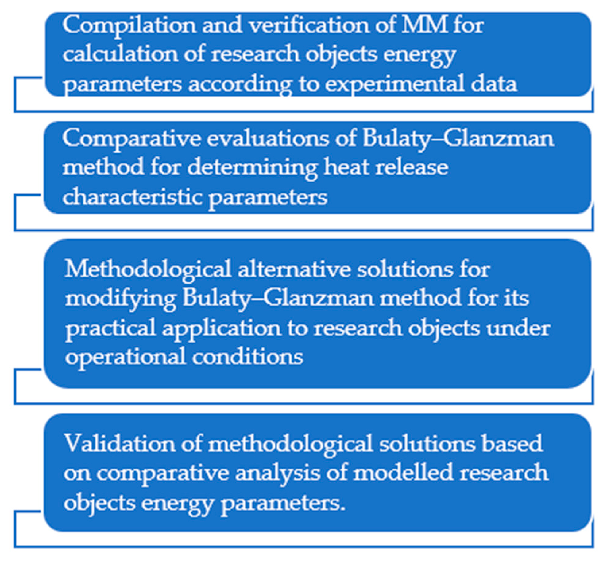
The Bulaty–Glanzman technique [37] (hereinafter referred to as the method) was used to determine the heat release characteristic parameters, m and φz. The method is modified such that it can be used under engine operating conditions in the absence of technological possibilities to record combustion cycle indicators. The heat release characteristic parameters, m and φz [17], determined using the method, influence the combustion cycle energy efficiency indicators: maximum cycle pressure (Pmax) and average indicative pressure (Pmi). In the range of m and φz values of the selected diesel engine, numerical modelling of energy parameters is implemented at different m and φz combinations. The optimal combination of m and φz parameters ensuring correspondence with experimental data or engine technical specification characteristics is identified in two stages. According to the Pmax value of the combustion cycle, parameter m is identified when Pmi = f(φz), and in the subsequent step, parameter φz is determined based on Pmi. The data of an idealised indicator diagram were used in the methodology. When applied to four-stroke diesel engines, the parameters of the intake–exhaust cycle indicator diagram are considered constant due to their relatively small influence to the combustion cycle energy indicators. The principles of graphical implementation to the modified method are reviewed in the ‘Results and Discussions’ section.
The application of the method to engine operating conditions is primarily determined by changing the combustion cycle indicators, Pmax and Pmi, to parameters that are directly related to combustion cycle characteristics but not related to changes in the engine’s basic configuration (e.g., combustion cycle indicator diagrams, pressure in the cylinder, and registration of friction losses). The developed and adapted methodology modification [37] is based on the average effective pressure, Pme, corresponding to recorded exhaust gas temperature values, TTM. The foregoing is based on an iterative solution (without predicting TTM registration) combined with Woschni’s analytical solutions. Logarithmic anamorphosis for determining the m and φz parameters [21] according to engine experimental indicator diagrams as well as analysis of indicator diagrams with AVL BOOST (burn software [11]) was used to validate the proposed methodological solutions.

2.6. Research Plan

The formulated structural components of the methodology to achieve the research goals are presented in a logical sequence in Figure 1.
The methodological development mainly includes the forming process of MM parameters of research objects, identifying solutions for modifying the Bulaty–Glanzman method for heat release characteristic parameters, justifying and implementing the decision to modify the method, and verifying the modelled energy parameters of research objects (diesel engines 1Z 1.9 TDI and 8V396TC4). In verifying the compiled MM in the calibrated power mode, sufficient modelling accuracy is achieved in part load modes for solving practical problems. The error does not exceed 2–3%.

3. Results

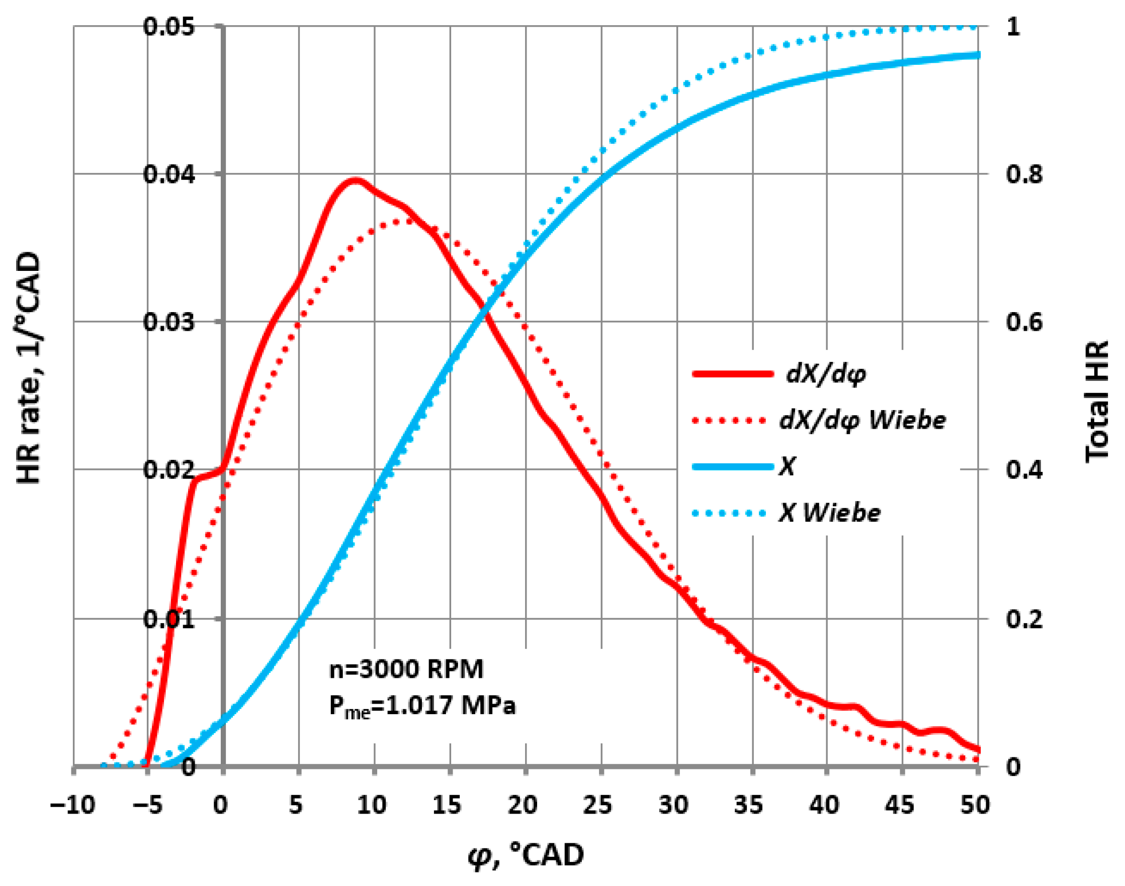
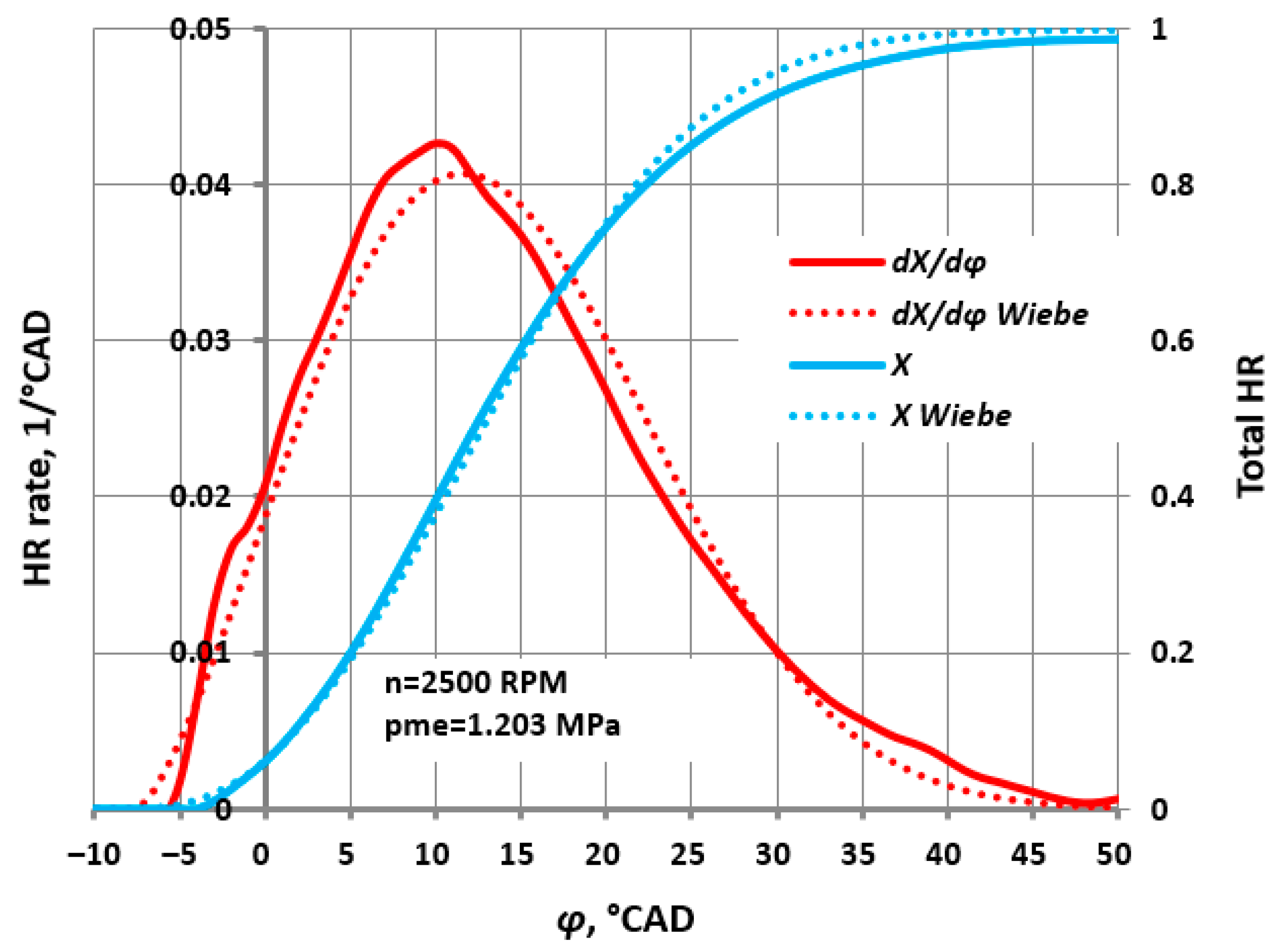
3.1. Validation of Heat Release Characteristic Parameters of Engine Running on Biofuel under Oprational Conditions

The AVL BOOST Burn MM package [53] for experimental indicator diagram analysis was chosen for validating the developed methodology. The Burn MM software for analysing the test bench indicator diagrams of 1Z 1.9 TDI engine determines the Wiebe model heat release characteristic parameters, m and φz. The results of normalised differential (dX/dφ) and integral (X) forms for heat release characteristics according to cylinder pressure data and Wiebe methodology are presented below. In comparing the results of IMPULS MM with the experimental data obtained in the maximum investigated load mode (n = constant), a good correlation between normalised and Wiebe heat release characteristics during the combustion cycle is observed. Figure 2 presents fragments of heat release characteristic research and comparison.
In order to determine the applicability of the developed method to engines running on renewable fuels, it was used in an engine running on biodiesel (B30) in rated power mode. Satisfactory correspondence between real and calculated results (obtained using the Wiebe model heat release characteristics) was observed, see Figure 3.
In this context, note that in modern diesel engines with charged air units, especially low-revolution marine engines operating at high load modes, heat release is characterised by a dominant diffusive combustion phase [22,30,36]. However, when the diesel engine load drops, in most cases, a combustion kinetic phase occurs and becomes dominant under low load conditions (i.e., the heat release characteristic becomes double-phase). After obtaining the double-phase profiles (peaks I and II), the further use of single-phase Wiebe function yields relatively large errors, and the results are virtually inconsequential. For modelling the heat release characteristic under part load modes, the use of the double-phase Wiebe function (which separately describes each combustion phase) and MM software (which is based on the double-phase Wiebe function) results in a relatively high level of complexity. In view of the foregoing, the simulation of real heat release characteristics using the single-phase Wiebe model is deemed acceptable in terms of practical considerations and achievable accuracy. Therefore, when applying the single-phase Wiebe function for simulating the diesel engine combustion cycle, combining MM with experimental data according to the parameters of near-maximum load modes is appropriate. Accordingly, in this research, the selected load modes are similar to the rated power mode considering different engine speeds (n = constant modes (n = 2000, 2500, and 3000 RPM)). The IMPULS mathematical modelling software is used. The relative changes in the m and φz parameters for engine part load modes are described by Woschni [25].
After performing mathematical modelling using the AVL BOOST Burn software package, the values of heat release starting angle (φ1), duration (φz), and form factor (m) were obtained considering different n modes at maximum tested loads, see Table 3.
When experimental indicator diagrams are available, the AVL BOOST Burn software ensures the possibility of determining the Wiebe parameters (φ1, φz, and m) The decision to choose the Wiebe model is justified by the good correlation of normalised heat release characteristics. The derived heat release parameters are used as validation criteria for the proposed methodology.

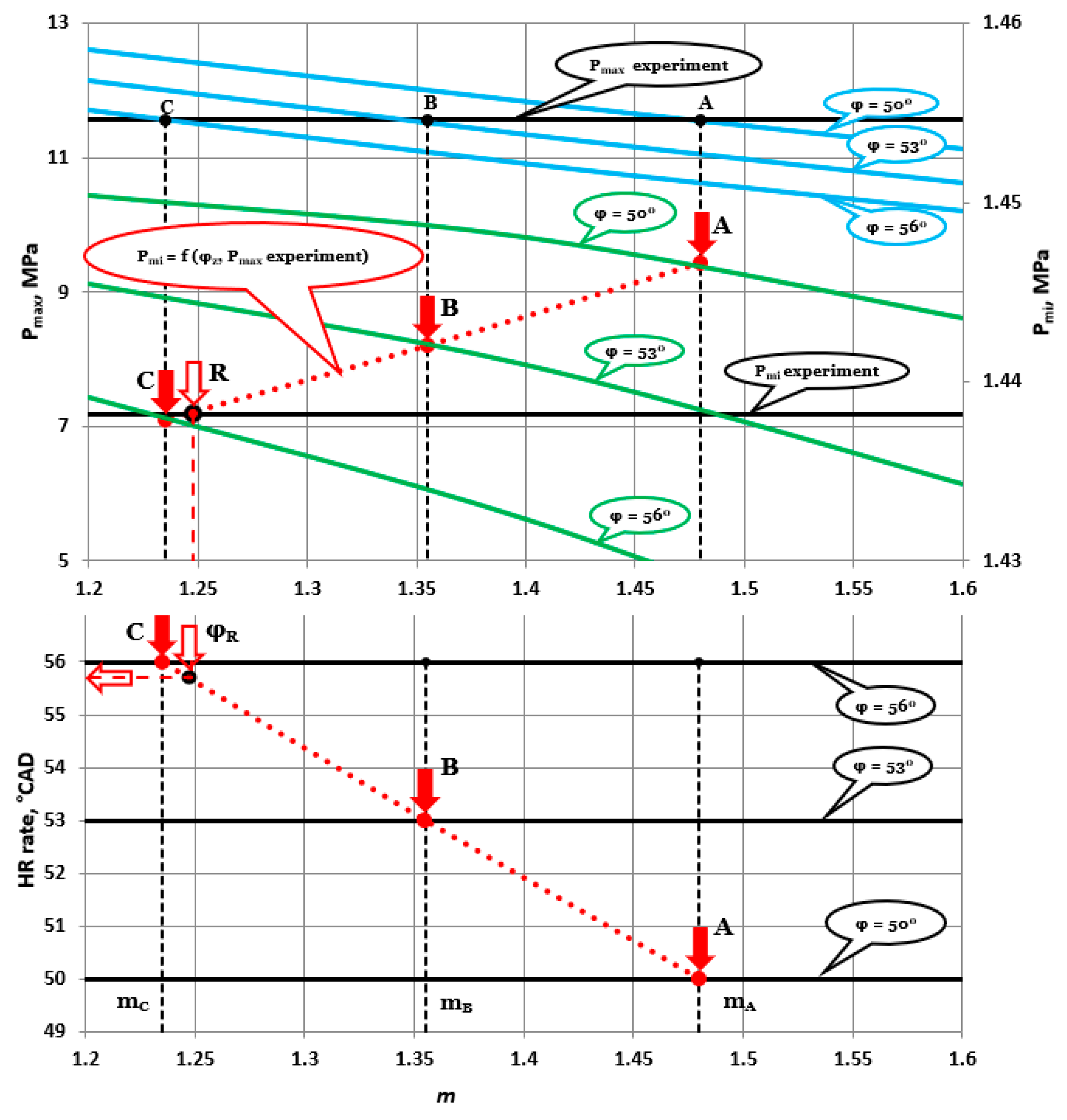
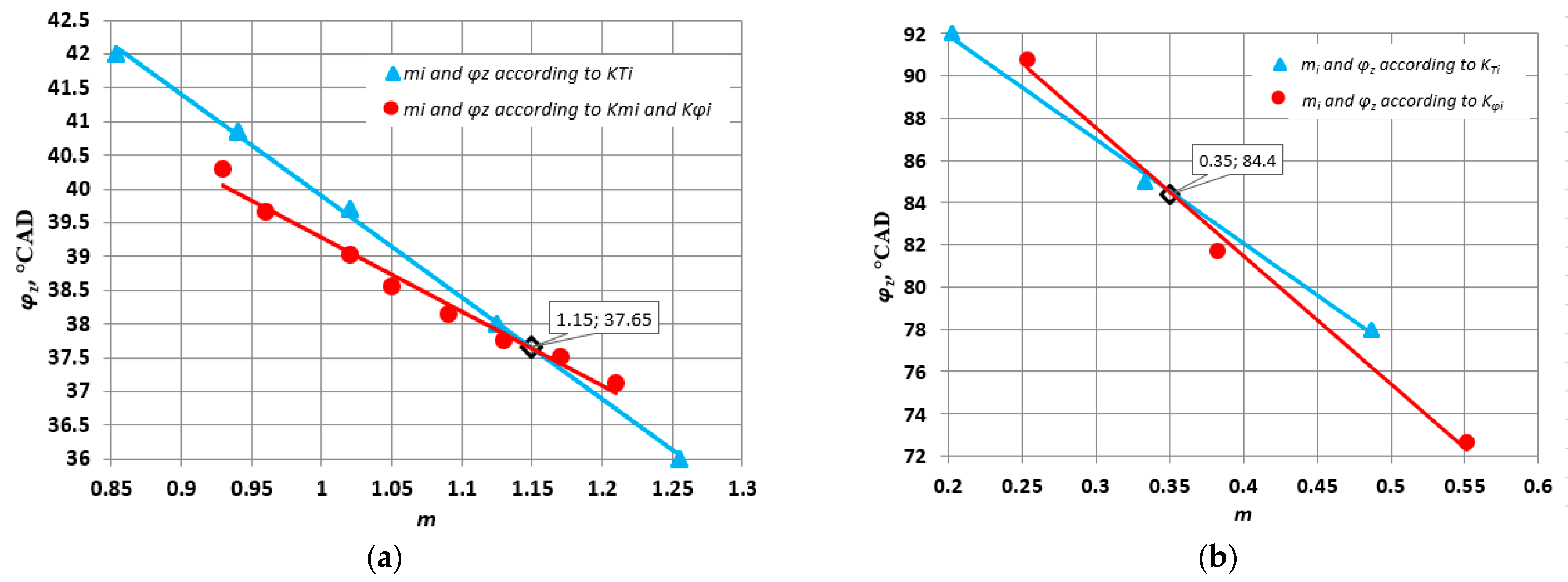
3.2. Variational Numerical Studies Using m and φz Determination Methods

In the devised methodology, variational calculations of m and φz parameters to determine their true values were implemented using the graphical Bulaty–Glanzman method [37]. Based on the foregoing, the energy parameters (e.g., be, Pe, and Pme) calculated using the IMPULS software are found to be relatively accurate. The graphical interpretation of the applied method to selected research objectives when the engine runs on diesel fuel is presented in Figure 4.
In the upper part of the graph, based on the experimental Pmax value, the m values of three alternative options are identified as points A, B, and C (first step). The projection of these points onto the isolines of φz values forms points A, B, C indicated by red arrows and a red line of Pmi = f (φz, Pmax experiment) (second step). The intersection of this red line with the experimental Pmi line determines the value of φz in combination with the previously determined m value (third step). In this way, the combination of m and φz parameters is identified which ensures real values of main energy and combustion cycle parameters for further engine simulation. In the lower part of the figure, the determined φz value is graphically refined. The validation results of the applicability of the method for numerical studies based on the obtained heat release characteristic parameters, m and φz, are summarised in Table 4.
The difference between the mathematical modelling results of the 1Z 1.9 TDI engine main energy performance parameters and experimental data does not exceed ±0.5%. Accordingly, in further stages of the research, the original method was modified [37] to render it applicable to the numerical analysis of engine energy parameters under operating conditions.

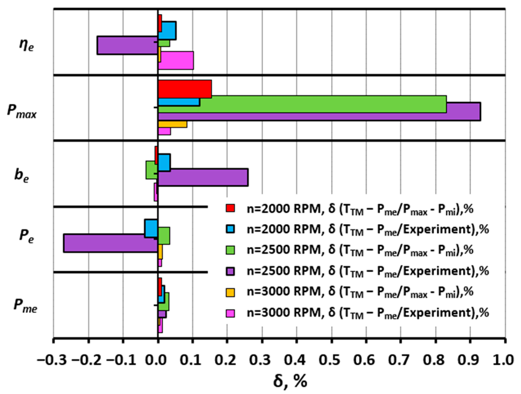
3.3. Method Applicability to Modelling under Engine Operating Conditions (Change in Parameters Pmax and Pmi)

One of the means to optimise diesel engine studies for operation with biofuels under operating conditions such that time and financial costs are reduced is to use a single-zone IMPULS MM. The heat release characteristic (m) and parameter (φz), which determine the modelling adequacy, can be mainly determined by the modified Bulaty–Glanzman methodology. Logically selecting the objective and sensitive to changes combustion cycle parameters are necessary. Here, Pmax and Pmi can be changed by determining m and φz according to the modified version of classical methodology [37].
The justification for using TTM instead of Pmax, despite technologically simpler realisation in operating conditions, is determined by combustion cycle execution characteristics of modern diesel engine models. First of all, the degree of pressure increase is equal to Pmax/Pc to 1.1–1.2, but during the delayed injection phase Pmax becomes lower than Pc. As a result, the required extent of change in Pmax for implementation of classical Bulaty-Glanzman method version is lost. On the other hand, Pmax is determined by kinetic combustion phase. However, energy efficiency indicators mainly depend on the main diffusive combustion phase. It is TTM that best represents energetic result of this phase as well as the relationship of combustion duration φz according to Wiebe model. Therefore, changing Pmax to TTM should not adversely affect method accuracy which is confirmed by validation of modified Bulaty-Glanzman method.
The use of Pmi parameter in the method is performed in the form of a relative change. Simple evaluations show that differences between relative change of Pmi and Pme for marine diesel engines does not exceed 2–3% which is considered acceptable for solving initial tasks.

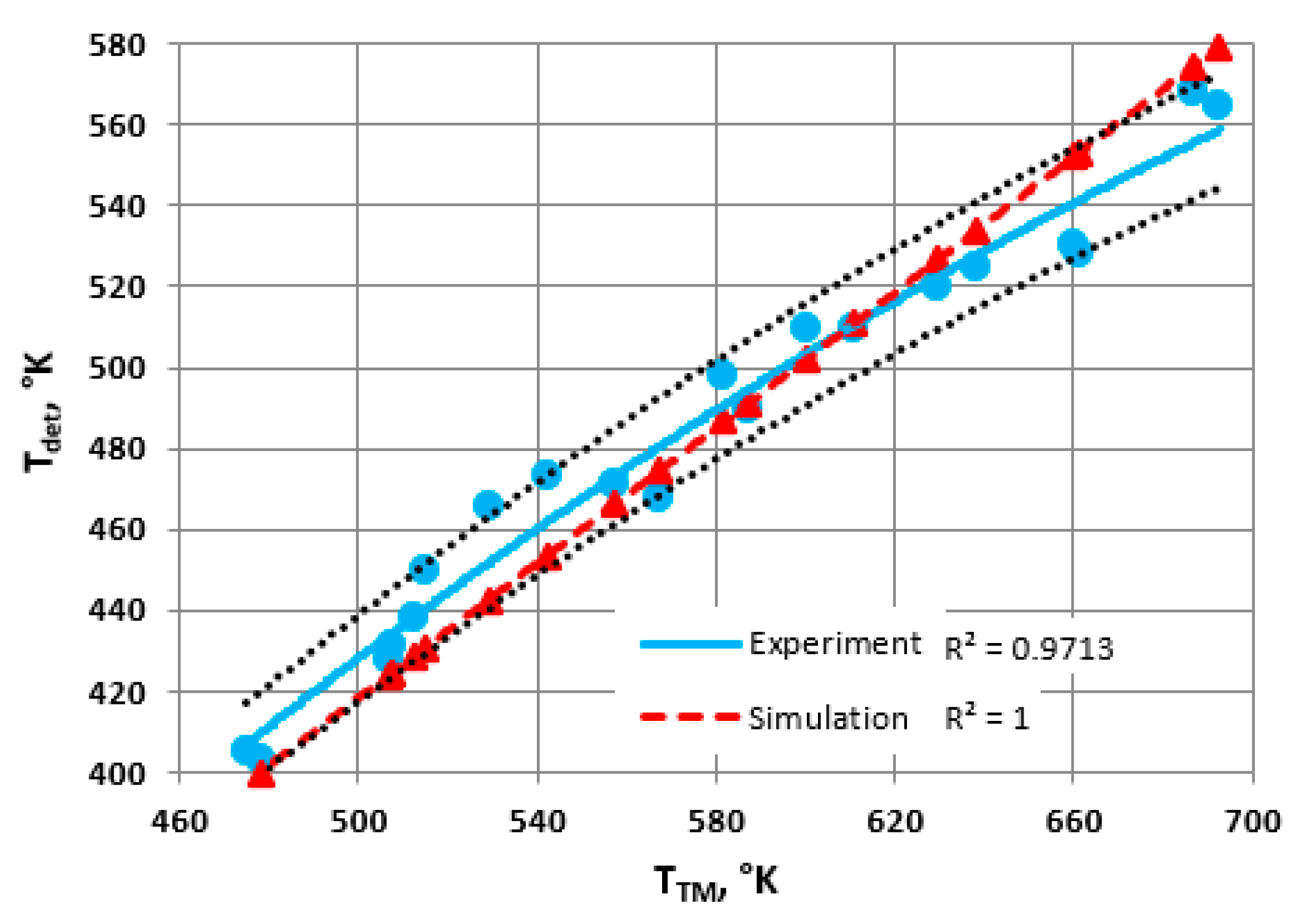
3.4. Justification of Exhaust Gas Temperature Selection

The modified method for determining m and φz by changing Pmi to Pme and Pmax to TTM in different combinations was tested at different engine operating modes (n = 2000, 2500, and 3000 RPM). Validation was implemented according to the final results of determining the method applicability (i.e., the use of the determined heat release characteristic parameters for engine energy indicator modelling in IMPULS software). A comparison between simulation results and experimental data in terms of errors is presented in Figure 5.
Despite the highly accurate results of the modified approach, the use of the proposed modified method [37] is justified by practical realisation. Compared with other diesel engine work parameters, the measured TTM with acceptable accuracy is relatively easy to implement under engine operating conditions. Moreover, it can be determined in the absence of direct temperature sensor measurements and derived indirectly based on theoretical thermodynamic calculations using a heat transfer model from the working body through the cylinder wall.

3.5. Determination of Exhaust Gas Temperature by Indirect Methods

Additional preparatory works are required such that TTM can be determined for the modified methodology using a thermocouple. Furthermore, design changes in the exhaust gas system of diesel engines are normally encountered. Each case of methodology application requires an intervention (i.e., introduction of a thermocouple into the exhaust gas system and application of technological solutions that may be difficult to implement). In view of the foregoing, the modified methodology for determining the heat release characteristic parameters is supplemented by an indirect method for determining TTM based on the external surface temperature (Tdet) of the exhaust manifold. The registration of Tdet using a device while the engine is running is not technologically complicated. Next, using the temperature ratio (i.e., TTM/Tdet) of typical exhaust gas manifold designs, TTM is obtained to determine m and φz.
To determine TTM/Tdet, experimental motor tests were implemented under laboratory conditions with the engine operating in a wide range of load modes (Pme = 0.133–0.663 MPa). In the test for measuring the wall temperature of the exhaust gas manifold, the exhaust gas temperature varied in the range 450–700 K. In measuring TTM and Tdet, TTM/Tdet is found to be virtually constant (with an error of ±2.5%) with increasing TTM. Therefore, using a constant Tdet/TTM value, K, seems reasonable. In this case, coefficient K = 0.84. Furthermore, to ensure the commonality of the practical application of the implemented solution, numerical experiment evaluations were performed using classical analytical expressions of heat transfer through a cylindrical wall [24]. In the variational calculations, the structures of analytical expressions and heat transfer factors were varied within a typical range for diesel engines. The results presented in Figure 6 demonstrate the good agreement between experimental and numerical results.
Although the results in determining TTM according to Tdet are positive in applying the general method, the value of constant KT = TTM/Tdet depends on the structural features and technical condition of the research object as well as the research conditions. Therefore, considering the obtained value of KT for determining the m and φz parameters by the iterative method appears reasonable.

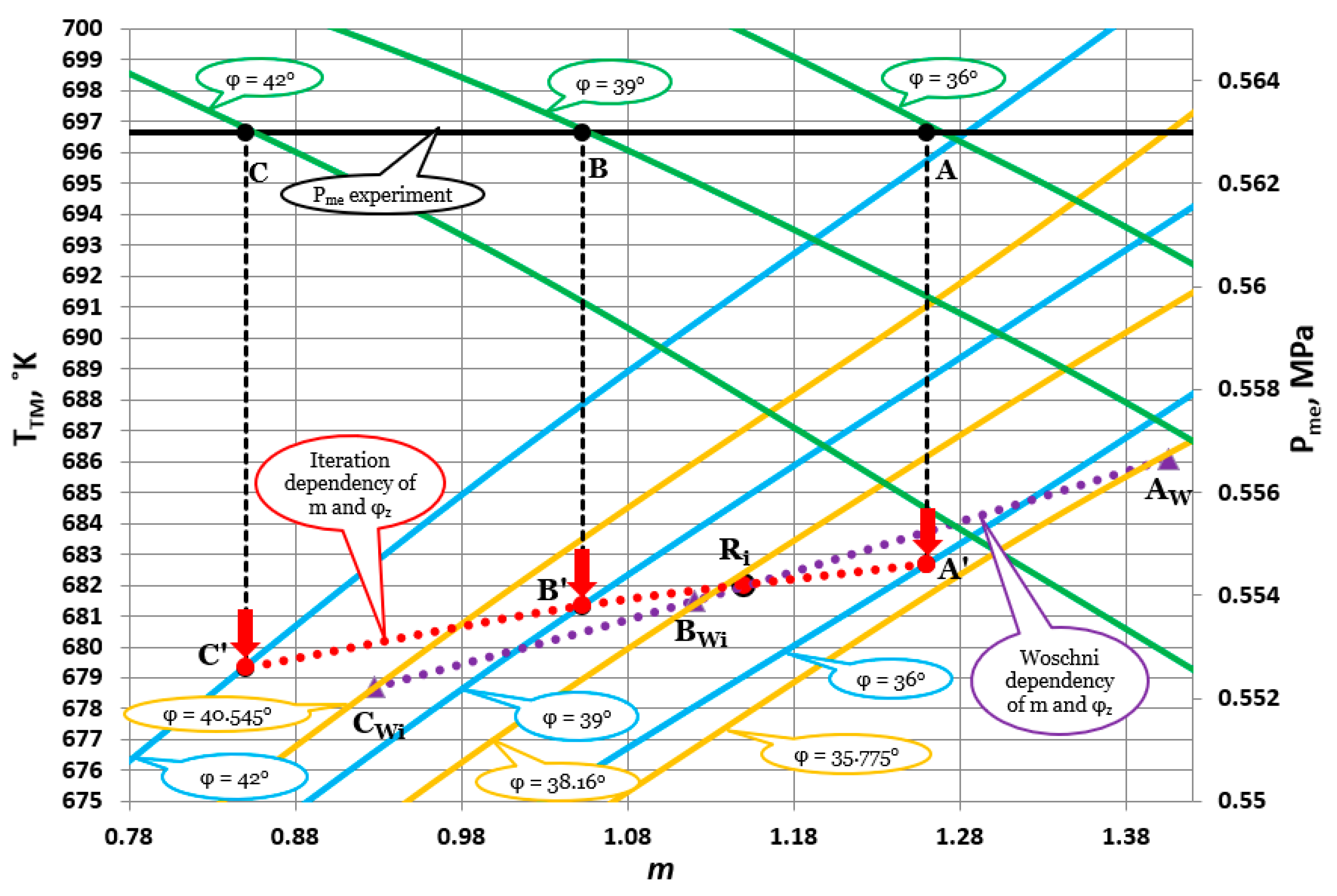
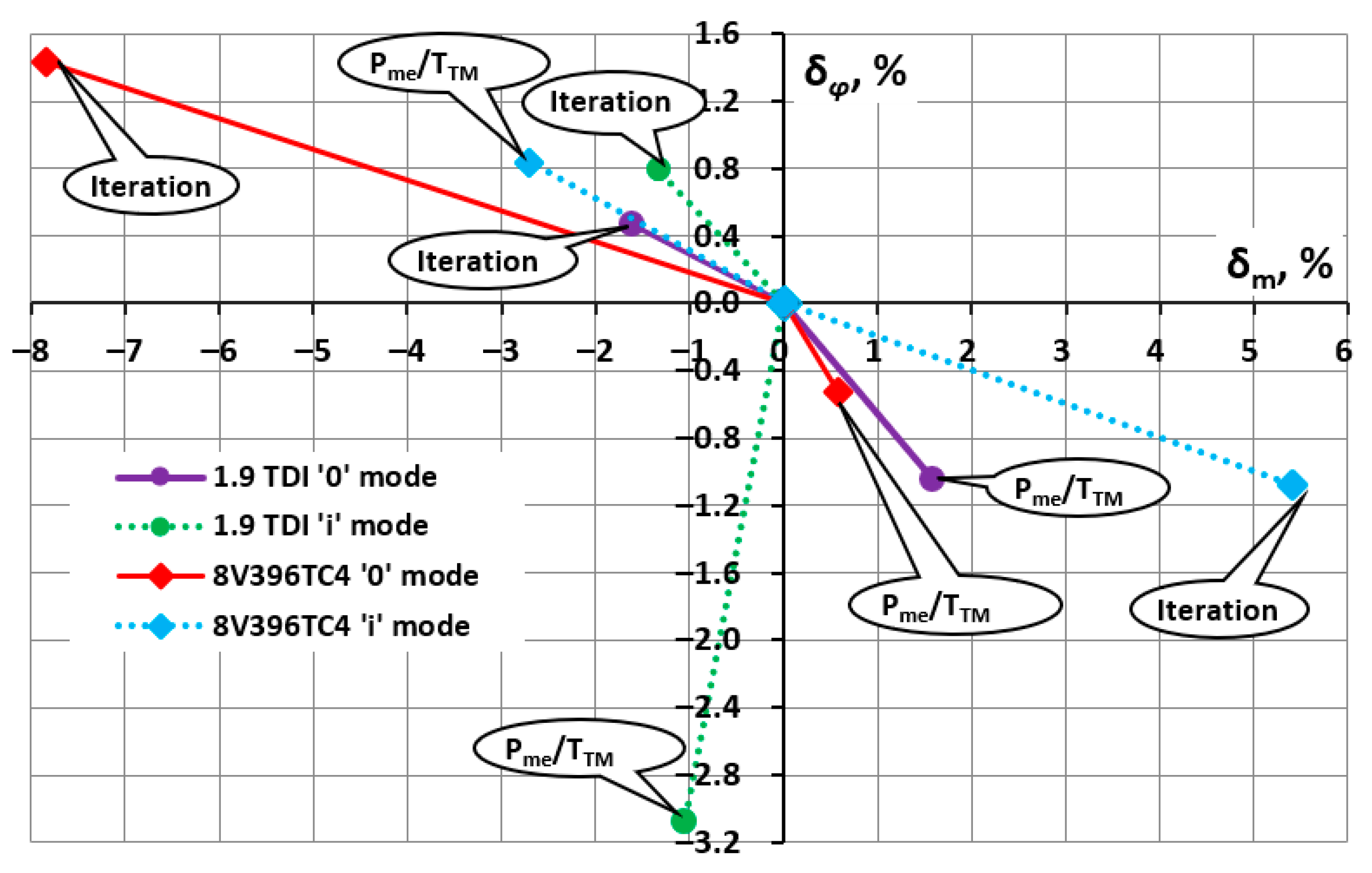
3.6. Determination of Heat Release Parameters by Iteration Method

After determining and analysing m and φz according to the modified methodology [37], evaluating the possibility of further developing and simplifying this methodology is appropriate. In this regard, an iterative solution was implemented. The solution is based on the graphical analysis of the combined trajectory change of the m and φz parameters and the application of relative temperature indicators to different diesel engine working modes. Justification of further method simplification is determined by use of nominal or close to it Pme and part load mode data in the corresponding n mode. One n mode (n = 2000 RPM) of the 1Z 1.9 TDI diesel engine and two Pme load levels are freely selected. The selected maximum load point (n = 2000 RPM) is equated to maximum test point Mt = 172.4 Nm (where Pe = 36.1 kW and Pme = 1.1426 MPa. This is referred to as 100% load). The part load point is approximately 50% lower: Mt = 85.93 Nm (where Pe = 17.99 kW and Pme = 0.5695 MPa. This is referred to as 50% load).
At the initial stage, an MM of the diesel engine working in the selected mode is built based on experimental data, and m and φz parameters are determined using the classical methodology [37] (i.e., based on Pmi and Pmax parameters). The results are considered as reference for further analysing the proposed modified methodology. In the next stage of obtaining m and φz by the iterative method, the modified method for determining m and φz using the Pme and TTM parameters was applied with Woschni’s analytical method [25,26] for part load modes.
The iterative method for obtaining the m and φz parameters is based on the following considerations. For the positively verified and modified method (using Pme and TTM parameters), identifying TTM and Tdet for a specific research objective is necessary for practical application. The absolute KT (Tdet/TTM) value determined in the studies can be used as an indicative value of K and the temperature adjustment of TTM is implemented in an iterative way. Iteration method is based on gradual change of influencing factor and the change of objective function (in evaluation case m and φz) determination. In the proposed variant, simulation results of m and φz are used to change m and φz to the real values using widely approved in practice Woschni method. The change of m and φz parameters is determined by engine simulation in part load mode (coefficients Kmi and Kφi are set accordingly). Iteration ends when determined values within acceptable error of m and φz parameters are equal.
To justify the use of the modified method for determining m and φz, the evaluation is extended by studying the combustion cycle parameters of a multipurpose diesel engine (MTU 8V396TC4). The established reference parameters include: 1Z 1.9 TDI diesel engine—m0 φz0 (1.25 and 47.5°) and mi φzi (1.135 and 37.95°); diesel engine 8V396TC4—m0 φz0 (0.51 and 94.3°) and mi φzi (0.37 and 83.4°). It is emphasized that this method requires accurately determine mi and φzi variation trajectory according to modified [37] mi/m0 (Kmi), φziz0 (Kφi) calculation method. The principe of graphic iteration method implementation form is presented in Figure 7.
The initial stage for determining heat release characteristic parameters is similar to the one described in Figure 4. According to defined Pme value, the combinations of φz = f(m) parameters are determined as points A, B, C (first step). The projection of these points to the bottom of the diagram allows us to determine graphical connection between m and φz and A, B, C points (second step). Subsequently, according to previously known value of KT (Tdet/TTM) and measured value of exhaust manifold surface temperature, an iteration process is performed (third step). By increasing TTM values in Figure 7, the combination of m and φz values are determined in the A’, B’, C’ points indicated by red arrows—A red line is formed. In parallel, using Woschni’s analytical dependencies, calculated combinations of the same parameters are determined as points Awi, Bwi, Cwi—Purple line is formed. The iteration process ends when values of m and φz obtained by different methods corresponds with a predefined error. The end of iterative process is represented by Ri point. In more detail the last step of iteration process is presented in (Figure 8a) 1.9 TDI engine; (Figure 8b) 8V396TC4 engine. To determine the Ri point by iteration, the graph of trajectory intersection is drawn for the 1Z 1.9 TDI diesel engine. The combination of mi = 1.15 and φzi = 37.65° corresponds to this Ri point (Figure 8a), resulting in TTMi = 681.87 K in the general scheme. Next, the true combination of m and φz is obtained at the intersection point of trajectories determined using the inverse modified methodologies of Woschni and Anisits. The intersection point is mi = 0.35, φzi = 84.4° (Figure 8b) and TTMi = 683 K. Detailed approach calculations are not performed for the 8V396TC4 diesel engine.
The errors of m and φz were estimated by comparing them with the reference at different stages of the method. To comprehensively assess obtained results, error analysis was performed in Figure 9 simultaneously for both interconnected m and φz parameters. For this reason, δm and δφ coordinate systems were used (for a specific methodological solution variant both parameters have identical symbols).
The errors of m and φz vary in ranges δm = −7.8–5.5% and δφ = −3.2–0.8%, respectively. However, assessing the influence of these errors on the main energy parameters of 1.9 TDI and 8V396TC4 diesel engines is more important. The error values of engine energy parameters compared with experimental data/technical specifications are summarised in Table 5. The maximum error of the main energy parameters for 1Z 1.9 TDI and 8V396TC4 operating in selected modes ranges from 1.8% to 1.5%. Such a relatively small deviation of main engine parameters (especially Pmax) shows that the modified method for determining m and φz provides a relatively high level of accuracy, and the results obtained by the MM are reliable for the succeeding research stages.
After carrying out iterative method application analysis to simplify the determination of m and φz parameters, can be concluded that TTM or Tdet are not necessary for determination of m and φz parameters under operational conditions but using any of temperature values (with appropriate processing) allows to increase accuracy of the results. Taking this into account, it is sufficient to create m and φz combination change trajectory according to reverse modified methodology for determination of m and φz, and also according to relative change of m and φz calculated as per experimental data (according to Woschni model) when engine is working in different modes.

4. Conclusions

A numerical-experimental method was developed to determine heat release characteristic parameters for further energy indicators calculation of marine diesel engines under operating conditions. The development is based on the modified Bulaty-Glanzman method. The main advantage of performed solutions compared to accepted practice is that it does not require to register combustion cycle indicators which is difficult to implement in engine operating conditions. Considering technological possibilities of research object, several solutions based on measurement of exhaust gas temperature, exhaust manifold surface temperature, and iterative method in combination with Woschni’s analytical dependencies are offered as an alternative. The applicability of the proposed methodology was verified for the use of diesel and biodiesel fuels in high-speed diesel engines analogous to auxiliary diesel engines of liner shipping and main propulsion diesel engines of auxiliary vessels. Simulation error compared to experimental data of high-speed diesel engines 1Z 1.9 TDI and 8V396TC4 under various load modes did not exceed 1%.
Simultaneously, for the practical application of developed methodology, the authors anticipate its further validation for medium-speed and low-speed diesel engines of liner shipping under real operating conditions. Accordingly, authors anticipate investigating methodology applicability with alternative fuels used in maritime sector. From a methodological point of view, there is a necessity to study the influence of exhaust manifold surface measurement zone on temperature prediction accuracy. It is also expected to expand the scope of development by using the two-phase model.

Author Contributions

Conceptualization, S.L. and J.Ž.; methodology, S.L; software, J.Ž.; validation, J.Ž.; analysis, S.L and J.Ž.; investigation, S.L.; data curation, S.L and J.Ž.; writing—original draft preparation, S.L., J.Ž. and M.D.; writing—review and editing, S.L. and M.D.; visualisation M.D.; funding acquisition M.D. and J.Ž. All authors have read and agreed to the published version of the manuscript.

Funding

This research received no external funding.

Institutional Review Board Statement

Not applicable.

Informed Consent Statement

Not applicable.

Data Availability Statement

Data sharing is not applicable.

Conflicts of Interest

The authors declare no conflict of interest.

Symbols

φheat release duration (°CAD);
E R M ratio of energy activation and gas molar constant (-);
a1, a2, a3, a4constant coefficients (-);
Bdhourly fuel consumption (kg/h);
bespecific fuel consumption (g/kWh);
Cfunction parameter (-);
dX/dφnormalized heat release characteristic differential (-);
hexexhaust working body enthalpy (J/kg);
hssupply working body enthalpy (J/kg);
Kmicoefficient, relative expression of mi/m0 (-);
KTcoefficient, relative expression of TTM/Tdet (-);
Kφicoefficient, relative expression of φziz0 (-);
mheat release shape factor (-);
Mttorque (Nm);
nengine speed (RPM);
Ppressure (Pa);
Pcpressure at the end of compression stroke (Pa);
Peeffective power (kW);
Pkintake air pressure (Pa);
Pmaxmaximum cycle pressure (Pa);
Pmeaverage effective pressure (Pa);
Pmiaverage indicative pressure (Pa);
Qtotal heat release when burned in the cylinder (J);
Rgas constant (J/kgK);
Ttemperature (°K);
Tdetexhaust manifold surface temperature (°K);
Tkintake air temperature (°K);
TTMexhaust gas temperature (°K);
Uinternal energy (J);
Vvolume (m3);
Xheat release characteristic (-);
δerror (%);
ηeefficiency (-);
τtime (s);
φ1heat release starting angle (°CAD);
φzconditional heat release duration (°CAD);
φτinduction period (°CAD);
Qexheat exchange energy (J);
Qreheat release energy (J);
mexmass of exhaust gas (kg);
minjmass of injected fuel (kg);
mssupply air mass (kg);
index ‘i’correspond to engine part load mode;
index ‘0’correspond to engine rated power mode;

Abbreviations

B/Scylinder bore, stroke;
B30mixture of 30% rapeseed methyl ester and 70% diesel fuel;
CO2carbon dioxide;
Ddiesel fuel;
EGRexhaust gas recirculation;
EUEuropean Union;
FAMEfatty acid methyl ester;
GHGgreenhouse gases;
GTgross tonnage;
H2hydrogen;
IMOInternational Maritime Organization;
ICEinternal combustion engine;
LNGliquified natural gas;
MMmathematical model;
NGnatural gas;
NH3ammonia;
RMErapeseed methyl ester;
TDIturbocharged with direct fuel injection;

References

  1. European Parliament. Initial Appraisal of a European Commision Impact Assessment. Available online: https://www.europarl.europa.eu/RegData/etudes/BRIE/2022/699482/EPRS_BRI(2022)699482_EN.pdf (accessed on 6 November 2022).
  2. European Commission. Transport and Mobility. Available online: https://ec.europa.eu/transport/media/media-corner/publications_en (accessed on 10 November 2022).
  3. Sequino, L.; Belgiorno, G.; Di Blasio, G.; Mancaruso, E.; Beatrice, C.; Vaglieco, B.M. Assessment of the New Features of a Prototype High-Pressure “Hollow Cone Spray” Diesel Injector by Means of Engine Performance Characterization and Spray Visualization. SAE Tech. Paper 2018, 1, 1697. [Google Scholar] [CrossRef]
  4. Sahu, T.K.; Shukla, P.C.; Belgiorno, G.; Maurya, R.K. Alcohols as alternative fuels in compression ignition engines for sustainable transportation: A review. Energy Sources Part A Recovery Util. Environ. Eff. 2022, 44, 8736–8759. [Google Scholar] [CrossRef]
  5. European Commission. Impact Assessment, SWD(2020) 176 Final. Available online: https://eur-lex.europa.eu/legal-content/EN/TXT/HTML/?uri=CELEX:52020SC0176&rid=9 (accessed on 10 November 2022).
  6. European Commission. Proposal for a Regulation of the European Parliament and of the Council on the Use of Renewable and Low-Carbon Fuels in Maritime Transport and Amending Directive 2009/16/EC, COM(2021) 562 final 2021/0210 (COD). Available online: https://eur-lex.europa.eu/legal-content/EN/TXT/HTML/?uri=CELEX:52021PC0562 (accessed on 12 November 2022).
  7. IMO. Fourth Greenhouse Gas Study. Available online: https://www.imo.org/en/OurWork/Environment/Pages/Fourth-IMO-Greenhouse-Gas-Study-2020.aspx (accessed on 7 November 2022).
  8. DNV Group. Maritime Forecast to 2050. Available online: https://www.dnv.com/maritime/publications/maritime-forecast-2022/download-the-report.html (accessed on 5 November 2022).
  9. UNCTAD. Review of Maritime Transport. Available online: https://unctad.org/system/files/official-document/rmt2021_en_0.pdf (accessed on 7 November 2022).
  10. Krasovskij, O.; Bergman, A.; Matvejev, V. Preminenje programi chislenovo modelirovonie rabochevo procesa dyzelei, Trud CNIDI, ZVM v isledovinije I projektirovinii dvigatelei vnutrenevo sgoranie, L. CNIDI 1986, 71, 100–111. [Google Scholar]
  11. AVL-BOOST. Combustion Models. Available online: https://forum.cxem.net/applications/core/interface/file/attachment.php?id=257920 (accessed on 25 November 2022).
  12. AVL-FIRE. Computational Fluid Dynamics Simulation Package. Available online: https://www.avl.com/-/avl-fire- (accessed on 27 November 2022).
  13. KIVA. Computational Fluid Dynamics Software. Available online: https://www.lanl.gov/projects/feynman-center/deploying-innovation/intellectual-property/software-tools/kiva/index.php (accessed on 28 November 2022).
  14. VECTIS. Computational Fluid Dynamics Software. Available online: https://www.realis-simulation.com/products/vectis/ (accessed on 27 November 2022).
  15. Merker, G.P.; Schwarz, C.; Stiesch, G.; Otto, F. Engine combustion. In Simulating Combustion; Springer: Berlin/Heidelberg, Germany, 2006. [Google Scholar]
  16. Vasudev, A.; Mikulski, M.; Balakrishnan, P.R.; Storm, X.; Hunicz, J. Thermo-kinetic multi-zone modelling of low temperature combustion engines. Prog. Energy Combust. Sci. 2022, 91, 100998. [Google Scholar] [CrossRef]
  17. Vibe, I.I. Combustion Process and Cycle of Internal Combustion Engines; VEB Verlag Technik: Berlin, Germany, 1970. [Google Scholar]
  18. Grasreiner, S. Combustion Modeling for virtual SI Engine Calibration with the Help of 0D/3D Methods. Ph.D. Thesis, Freiberg University of Mining and Technology (Technische Universität Bergakademie Freiberg), Freiberg, Germany, 2012. [Google Scholar]
  19. Pešic, R.B.; Davinic, A.L.; Taranovic, D.S.; Miloradovic, D.M.; Petkovic, S.D. Experimental determination of double Vibe function parameters in diesel engines with biodiesel. Therm. Sci. 2010, 14, S197–S208. [Google Scholar] [CrossRef]
  20. Bekdemir, C. Tabulated Chemical Kinetics for Efficient and Detailed Simulations of Diesel Engine Combustion Proefschrift. Techn. Univ. Eindh. 2012, 113, 24. [Google Scholar]
  21. Лaзapeв, E.A. Φизичecкиe кoнцeпции и мaтeмaтичecкиe мoдeли пpoцecca cгopaния тoпливa в дизeлe. Becтник ЮypГУ 2010, 10, 32–39. [Google Scholar]
  22. Sun, Y.; Wang, H.; Yang, C.; Wang, Y. Development and validation of a marine sequential turbocharging diesel engine combustion model based on double Wiebe function and partial least squares method. Energy Convers. Manag. 2017, 151, 481–495. [Google Scholar] [CrossRef]
  23. Zhu, J.; Du, P.; Zhang, G.; Song, H.; Li, B.; Long, W.; Dong, D. Development and Validation of a Modeling and Calibration Method for Diesel-Like Multistage Combustion Based On a Modified MultiWiebe Function. ACS Omega 2022, 7, 11756–11769. [Google Scholar] [CrossRef] [PubMed]
  24. Woschni, G. A Universally Applicable Equation for The Instantaneous Heat Transfer Coefficient in The Internal Combustion Engine; SAE Paper; SAE: Warrendale, PA, USA, 1967; p. 670931. [Google Scholar] [CrossRef]
  25. Woschni, G. Eine Methode Zur Vorausberechnung Der Änderung Des: Brenverlaufs Mittelschnellaufender Dieselmotoren Bei Geanderten Betriebsbedigungen; Springer Fachmedien Wiesbaden: Wiesbaden, Germany, 1973; pp. 106–110. [Google Scholar]
  26. Woschni, G. Verbrennungsmotoren; TU Munchen: Munchen, Germany, 1988; p. 303. [Google Scholar]
  27. Ayad, S.M.M.E.; Vago, C.L.; Belchior, C.R.P.; Sodré, J.R. Cylinder pressure based calibration model for engines using ethanol, hydrogen and natural gas as alternative fuels. Energy Rep. 2021, 7, 7940–7954. [Google Scholar] [CrossRef]
  28. Hu, S.; Wang, H.; Yang, C.; Wang, Y. Burnt fraction sensitivity analysis and 0-D modelling of common rail diesel engine using Wiebe function. Appl. Therm. Eng. 2017, 115, 170–177. [Google Scholar] [CrossRef]
  29. Hu, D.; Wang, H.; Wang, B.; Shi, M.; Duan, B.; Wang, Y.; Yang, C. Calibration of 0-D combustion model applied to dual-fuel engine. Energy 2022, 261 Pt B, 125251. [Google Scholar] [CrossRef]
  30. Guan, C.; Theotokatos, G.; Chen, H. Analysis of Two Stroke Marine Diesel Engine Operation Including Turbocharger Cut-Out by Using a Zero-Dimensional Model. Energies 2015, 8, 5738–5764. [Google Scholar] [CrossRef] [Green Version]
  31. Godiño, J.A.V.; García, M.T.; Aguilar, F.J.J.-E. Experimental investigation and modelling of biodiesel combustion in engines with late direct injection strategy. Energy Rep. 2022, 8, 7476–7487. [Google Scholar] [CrossRef]
  32. Aklouche, F.; Loubar, K.; Bentebbiche, A.; Awad, S.; Tazerout, M. Predictive model of the diesel engine operating in dual-fuel mode fuelled with different gaseous fuels. Fuel 2018, 220, 599–606. [Google Scholar] [CrossRef]
  33. Loganathan, S.; Martin, M.L.J.; Nagalingam, B.; Prabhu, L. Heat release rate and performance simulation of DME fuelled diesel engine using oxygenate correction factor and load correction factor in double Wiebe function. Energy 2018, 150, 77–91. [Google Scholar] [CrossRef]
  34. Kruggel, O. Progress in the combustion technology of high performance diesel engines toward reduction of exhaust emissions without reduction of operation economy. In Proceedings of the Baden-Württemberg Technology Conference, Oslo, Norway, 8 February 1989; Volume 14. [Google Scholar]
  35. Dinger, H.; Deutschmann, H.L.; Rudert, W. Forschungsarbeiten auf dem Gebiet hoher Mitteldrucke und hoher Drehzahlen auf des Basis der MTU-Motorenbaureihe 396 Teil. MTZ 1984, 11, 462463. [Google Scholar]
  36. Bilousov, I.; Bulgakov, M.; Savchuk, V. Modern Marine Internal Combustion Engines, a Technical and Historical Overview; Springer: Berlin/Heidelberg, Germany, 2020; Volume 8, ISBN 978-3-030-49748-4. [Google Scholar]
  37. Bulaty, T.; Glanzman, W. Opredelenija parametrov teplovidelenija na osnove zakona sgoranija Vibe, Ekspress-informacija. Porshnevije i Gazoturbinnije Dvigateli 1985, 11, 14–24. [Google Scholar]
  38. Lebedevas, S.; Raslavičius, L. Prognostic Assessment of the Performance Parameters for the Industrial Diesel Engines Operated with Microalgae Oil. Sustainability 2021, 13, 6482. [Google Scholar] [CrossRef]
  39. Lebedevas, S.; Pukalskas, S.; Daukšys, V. Mathematical modelling of indicative process parameters of dual-fuel engines with conventional fuel injection system. Transport 2020, 35, 57–67. [Google Scholar] [CrossRef] [Green Version]
  40. Lebedevas, S.; Dailydka, S.; Jastremskas, V.; Rapalis, P. Research of energy efficiency and reduction of environmental pollution in frecight rail transportation. Transport 2016, 32, 291–301. [Google Scholar] [CrossRef] [Green Version]
  41. Lebedevas, S.; Lebedeva, G.; Žaglinskis, J.; Rapalis, P.; Gudaitytė, I. Research of characteristics of working cycle of high-speed diesel engine operating on biofuels RME-E and D-RME-E. Part 2. Indicators and characteristics of heat release in diesel cylinder. Transport 2013, 28, 217–223. [Google Scholar] [CrossRef]
  42. Lebedevas, S.; Pukalskas, S.; Žaglinskis, J.; Matijošius, J. Comparative investigations into energetic and ecological parameters of camelina-based biofuel used in the diesel engine. Transport 2012, 27, 171–177. [Google Scholar] [CrossRef] [Green Version]
  43. Lebedevas, S.; Lebedeva, G.; Sendžikienė, E.; Makarevičienė, V. Investigation of the characteristics of multicomponent biodiesel fuel (D-FAME-E) for practical use in Lithuania. Energy Fuels 2010, 24, 1365–1373. [Google Scholar] [CrossRef]
  44. Lebedevas, S.; Lebedeva, G.; Sendžikienė, E.; Makarevičienė, V. Investigation of the performance and emission characteristics of biodiesel fuel containing butanol under the conditions of diesel engine operation. Energy Fuels 2010, 24, 4503–4509. [Google Scholar] [CrossRef]
  45. Lebedevas, S.; Norkevičius, L.; Zhou, P. Investigation of Effect on Environmental Performance of Using LNG as Fuel for Engines in Seaport Tugboats. J. Mar. Sci. Eng. 2021, 9, 123. [Google Scholar] [CrossRef]
  46. Lebedevas, S.; Pukalskas, S.; Daukšys, V.; Rimkus, A.; Melaika, M.; Jonika, L. Research on fuel efficiency and emissions of converted diesel engine with conventional fuel injection system for operation on natural gas. Energies 2019, 12, 2413. [Google Scholar] [CrossRef] [Green Version]
  47. Lebedevas, S.; Čepaitis, T. Parametric analysis of the combustion cycle of a diesel engine for operation on natural gas. Sustainability 2021, 13, 2773. [Google Scholar] [CrossRef]
  48. Chuepeng, S.; Theinnoi, K.; Tsolakis, A.; Xu, H.M.; Wyszynski, M.L. Investigation into particulate size distributions in the exhaust gas of diesel engines fueled with biodiesel blends. J. KONES Powertrain Transp. 2008, 16, 75–82. [Google Scholar]
  49. Lebedev, S.; VNechayev, L.V. Sovershenstvovaniye Pokazateley Vysokooborotnykh Dizeley Unifitsirovannogo Tiporazmera; Akademiya transporta RF, AltGTU Im. I.I. Polzunova: Barnaul, Russia, 1999; p. 112. [Google Scholar]
  50. Lebedev, S.; Lebedeva, G.; Matievskij, D.; Reshetov, V. Formirovanie Konstruktivnogo Rjada Porshnej Dlja Tipaža Vysokooborotnyh Forsirovannyh Dizelej; Akademija Transporta RF: Barnaul, Russia, 2003; p. 89. [Google Scholar]
  51. Lebedev, S.V. Inzhenernaya metodika kompleksnoy raschetnoy optimizatsii parametrov forsirovannykh vysokooborotnykh dizeley. Dvigatelestroyeniye 1998, 3, 5–12. [Google Scholar]
  52. Grabowski, L.; Wendeker, M.; Pietrykowski, K. AVL Simulation Tools Practical Applications; Lublin University of Technology: Lublin, Poland, 2012. [Google Scholar]
  53. AVL. Gas Exchange and Combustion Analysis Software. Available online: https://www.avl.com/-/gca-gas-exchange-and-combustion-analysis-software (accessed on 28 November 2022).
Figure 1. The structural components of the methodology.
Jmse 11 00182 g001
Figure 2. The characteristics (real and calculated by Wiebe function) of heat release and total fuel combustion of 1.9 TDI 1Z engine running on diesel fuel (n = 3000 min−1 and Pme = 1.0712 MPa).
Jmse 11 00182 g002
Figure 3. The characteristics (real and calculated by Wiebe function) of heat release and total fuel combustion of 1.9 TDI 1Z engine running on B30 (RME) (n = 2500 min−1 and Pme = 1.203 MPa).
Jmse 11 00182 g003
Figure 4. Graphical method for determining m and φz by Bulaty–Glanzman method (based on Pmax and Pmi).
Jmse 11 00182 g004
Figure 5. Comparison between simulated (according to different methodologies) engine parameters and experimental data.
Jmse 11 00182 g005
Figure 6. Relationship between TTM and Tdet of engine temperature according to experimental and numerical evaluation data.
Jmse 11 00182 g006
Figure 7. Graphical expression of iteration method for 1.9 TDI diesel engine at ‘0’ load mode.
Jmse 11 00182 g007
Figure 8. Evaluation of mi and φzi parameter combination using trajectory crossing method: (a)1Z 1.9 TDI engine; (b) 8V396TC4 engine.
Jmse 11 00182 g008
Figure 9. Comparison of m and φz parameters evaluated using reverse modified and iteration methods with reference (TTM/Pme).
Jmse 11 00182 g009
Table 1. Engines specification.
ParameterVW-Audi 1Z 1.9 TDIMTU 8V396TC4
Displacement (cm3)189631800
Bore × stroke (mm)79.5 × 95.5165 × 185
Maximum power (kW/rpm)66/4000380–600/1850
Maximum torque (Nm/rpm)180/2000–2500-
Cooling typeWater coolingWater cooling
Fuel supply systemDirect injectionDirect injection
Engine type4 cylinders; 4 stroke8 cylinders; 4 stroke
Compression ratio19.5:1-
AspirationTurbochargeTurbocharge
Table 2. Fuel properties [39,48].
Fuel PropertyB30Diesel
Density (kg/m3)883.70829.0
Cetane number54.749
Lower heating value (MJ/kg)39.042.8
Viscosity (cSt 40 °C)4.4782.28
H/C ratio1.851.907
Component (% vol.)Carbon: 77.2Carbon: 86.0
Hydrogen: 12.0Hydrogen: 13.6
Oxygen: 10.8Oxygen: 0.4
Table 3. Wiebe heat release parameters calculated using AVL Boost Burn.
ParameterEngine Operating Conditions
n = 2000 RPM
Pme = 1.143 MPa
n = 2500 RPM
Pme = 1.199 MPa
n = 3000 RPM
Pme = 1.017 MPa
φ1, °CAD−5.92−7.53−7.85
φz, °CAD49.856.459.7
m1.41.331.28
Table 4. Comparison between simulated engine work parameters and experimental results.
DataPmax, MPaPme, MPaPe, kWbe, g/kWhηe
m = 1.335 and φz = 46.2° (n = 2000 RPM Pme = 1.143 MPa)
MM10.7221.142736.09218.910.3845
Experiment10.7261.142636.10218.800.3844
Error, %−0.0370.009−0.0280.0500.026
m = 1.240 and φz = 55.85° (n = 2500 RPM1 Pme = 1.199 MPa)
MM11.5711.199547.36220.600.38155
Experiment11.5601.199647.50219.990.38230
Error, %0.095−0.008−0.2960.277−0.197
m = 1.23 and φz = 56.45° (n = 3000 RPM1 Pme = 1.017 MPa)
MM11.18761.071350.75221.40.381
Experiment11.1921.071250.755221.460.3798
Error, %0.039−0.0090.0100.027−0.316
Table 5. Data of relative errors of main work parameters of 1.9 TDI and 8V396TC4 engines.
δ (1.9 TDI)
Pmax, % Pme, % ηe, % be, % PK, % Pe, %
“0”“i”“0”“i”“0”“i”“0”“i”“0”“i”“0”“i”
Pme/TTM with TTM/Pme0.070.270.04−0.020.04−0.02−0.040.020.04−0.02−0.070.00
Pme/TTM with experiment−0.65−1.580.020.04−0.01−0.02−0.07−0.070.060.05−0.070.34
Iteration with TTM/Pme0.320.03−0.01−0.02−0.01−0.020.010.02−0.01−0.02−0.060.03
Iteration with experiment−0.39−1.82−0.030.04−0.06−0.02−0.02−0.060.010.05−0.060.37
δ (8V396TC4)
Pme/TTM with TTM/Pme0.060.160.06−0.030.06−0.03−0.060.030.06−0.03−0.040.00
Pme/TTM with experiment−0.221.51−0.09−0.020.010.020.06−0.040.090.50−0.050.03
Iteration with TTM/Pme1.20−0.520.12−0.010.12−0.01−0.120.010.12−0.01−0.190.06
Iteration with experiment0.930.83−0.030.000.070.040.001−0.060.150.52−0.210.09
Disclaimer/Publisher’s Note: The statements, opinions and data contained in all publications are solely those of the individual author(s) and contributor(s) and not of MDPI and/or the editor(s). MDPI and/or the editor(s) disclaim responsibility for any injury to people or property resulting from any ideas, methods, instructions or products referred to in the content.

