
Review on Fixed and Floating Offshore Structures. Part I: Types of Platforms with Some Applications

 ,
,
Abstract
:1. Introduction
2. Overview of Platform Installations
- (a)
- Jack-up rig or Tender rig for extraction of oil/gas, drilling and templates (jackets) in water depths up to 150 m;
- (b)
- A semi-submersible drilling rig with a template (jacket) platform for extraction of oil/gas, at sea depths of 150 to 300 m;
- (c)
- A semi-submersible drilling rig with guyed-tower platforms for oil/gas extraction at depths of 300 to 400 m;
- (d)
- Semi-submersible drilling rig with tension leg platform or semi-submersible oil/gas extraction platform for water depths of 400 m to 1800 m;
- (e)
- Drillship rig with tension leg, subsea system, or spar platforms for oil/gas extraction in depths greater than 1800 m;
- (f)
- Floating production storage and offloading (FPSO) are found operating in water depths ranging from 200 m to more than 3000 m [260] and depending on the environmental condition, they are maintained in position using either a spread or turret mooring system.
2.1. Floating Production Systems
2.2. Fixed Offshore Platform Design
2.3. Subsea System
3. Types of Offshore Platforms
3.1. Moveable Offshore Drilling Platforms
3.2. Drilling Barges
3.3. Jackup Drilling Platforms/Rigs
3.4. Offshore Wind Turbine Platforms
3.5. Semisubmersible Platform
3.6. Dynamic Positioned Drillships
3.7. SPAR Platforms
3.8. Jacket Platforms
3.9. Compliant Towers (Tower Platforms)
3.10. Tension Leg Platform and Seastar Platform
3.11. FPSO
3.12. Concrete Gravity-Based Structure (GBS)
4. Applications of Offshore Platforms
4.1. Advantages and Disadvantages of Offshore Platforms
4.2. Exploratory Application of Offshore Platforms
4.2.1. Luxury Cruise
4.2.2. Offshore Rocket Launch and Landing Platform
4.2.3. Converted Offshore Structures
5. Conclusions and Recommendations for Future Research
Author Contributions
Funding
Institutional Review Board Statement
Informed Consent Statement
Data Availability Statement
Acknowledgments
Conflicts of Interest
Abbreviations
| 2D | Two-Dimensional |
| 3D | Three-Dimensional |
| AISC | American Institute of Steel Construction |
| API | American Petroleum Institute |
| ASTM | American Society for Testing and Materials |
| BOEM | Bureau of Ocean Energy Management |
| BOP | Blowout Preventer |
| CFD | Computational Fluid Dynamics |
| CEV | Carbon Equivalent Value |
| CNN | Cable News Network |
| CPU | Central Processing Unit |
| CT | Compliant Tower |
| DD | Semi Deep Draft Semisubmersible |
| DDCV | Deep-Draft Caisson Vessel |
| DNV | Det Norske Veritas |
| DoF | Degree of Freedom |
| DTS | Dry-Tree Semisubmersible |
| FDPSO | Floating Drilling Production Storage and Offloading |
| FLNG | Floating Liquid Natural Gas |
| FOWT | Floating Offshore Wind Turbine |
| FPS | Floating Production Systems |
| FPSO | Floating, Production, Storage and Offloading |
| FPU | Floating Production Units |
| FSU | Floating Storage Units |
| FSO | Floating Storage and Offloading |
| GBS | Gravity Base Structure |
| GoM | Gulf of Mexico |
| IMA | International Maritime Association |
| MET-INT | Metocean Interim |
| MODU | mobile offshore drilling unit |
| MOPU | Mobile Offshore Production Unit |
| NOAA | National Oceanic and Atmospheric Administration |
| NREL | National Renewable Energy Laboratory |
| OSV | Offshore Support Vessel |
| PSV | Platform Service Vessel |
| RAO | Respond Amplitude Operator |
| RP | Recommended Practice |
| SCR | Steel Catenary Risers |
| SOV | Service Offshore Vessel |
| SpaceX | Space Exploration Technologies |
| SPAR | Single Point Anchor Reservoir |
| SPM | single point mooring |
| TLP | Tension Leg Platform |
| TTR | Top Tension Riser |
| U.A.E. | United Arab Emirates |
| U.S.A. | United States of America |
| VIV | Vortex Induced Vibration |
| VLCC | Very Large Crude Carrier |
| WEC | Wave Energy Converter |
| WER | World Energy Report |
Appendix A


References
- Chakrabarti, S.K. Handbook of Offshore Engineering, 1st ed.; Elsevier: Plainfield, IL, USA, 2005; Volume 1. [Google Scholar]
- Haritos, N. Introduction to the analysis and design of offshore structures—An overview. Electron. J. Struct. Eng. (eJSE) 2007, 7, 55–65. Available online: https://ejsei.com/EJSE/article/download/65/64 (accessed on 12 February 2022).
- Söding, H.; Blok, J.J.; Chen, H.H.; Hagiwara, K.; Isaacson, M.; Jankowski, J.; Jefferys, E.R.; Mathisen, J.; Rask, I.; Richer, J.-P.; et al. Environmental forces of offshore structures: A state-of-the-art review. Mar. Struct. 1990, 3, 59–81. [Google Scholar] [CrossRef]
- Amiri, N.; Shaterabadi, M.; Reza Kashyzadeh, K.; Chizari, M. A comprehensive review on design, monitoring, and failure in fixed offshore platforms. J. Mar. Sci. Eng. 2021, 9, 1349. [Google Scholar] [CrossRef]
- Amaechi, C.V.; Reda, A.; Butler, H.O.; Ja’e, I.A.; An, C. Review on fixed and floating offshore structures. Part II: Sustainable design approaches and project management. J. Mar. Sci. Eng. 2022, 10, 973. [Google Scholar] [CrossRef]
- El-Reedy, M. Offshore Structures: Design, Construction and Maintenance; Imprint: Gulf Professional Publishing; Elsevier: London, UK, 2012. [Google Scholar] [CrossRef]
- Bai, Y.; Bai, Q. Subsea Engineering Handbook; Elsevier: Oxford, UK, 2010. [Google Scholar]
- Wilson, J. Dynamics of Offshore Structures, 2nd ed.; John Wiley & Sons: Hoboken, NJ, USA, 2022. [Google Scholar]
- Ladeira, I.; Márquez, L.; Echeverry, S.; Le Sourne, H.; Rigo, P. Review of methods to assess the structural response of offshore wind turbines subjected to ship impacts. Ships Offshore Struct. 2022. ahead-of-print. [Google Scholar] [CrossRef]
- Jaculli, M.A.; Leira, B.J.; Sangesland, S.; Morooka, C.K.; Kiryu, P.O. Dynamic response of a novel heave-compensated floating platform: Design considerations and the effects of mooring. Ships Offshore Struct. 2022. ahead-of-print. [Google Scholar] [CrossRef]
- Al-Sharif, A.A. Design, fabrication and installation of fixed offshore platforms in the Arabian Gulf. In Proceedings of the Fourth Saudi Engineering Conference, Dhahran, Saudi Arabia, 5–8 November 1995; pp. 99–105. [Google Scholar]
- Al-Yafei, E.F. Sustainable Design for Offshore Oil and Gas Platforms: A Conceptual Framework for Topside Facilities Projects. Ph.D. Thesis, School of Energy, Geoscience, Infrastructure & Society, Heriot Watt University, Edinburgh, UK, 2018. Available online: https://www.ros.hw.ac.uk/bitstream/handle/10399/3513/Al-YafeiE_0418_egis.pdf?sequence=1&isAllowed=y (accessed on 12 February 2022).
- Kreidler, T.D. The Offshore Petroleum Industry: The Formative Years, 1945–1962. Ph.D. Thesis, History Department, Texas Tech University, Lubbock, TX, USA, 1997. Available online: https://citeseerx.ist.psu.edu/viewdoc/download?doi=10.1.1.455.2343&rep=rep1&type=pdf (accessed on 12 February 2022).
- Sadeghi, K. An overview on design, construction and installation of offshore template platforms suitable for Persian Gulf oil/gas fields. In Proceedings of the First International Symposium on Engineering, Artificial Intelligence and Applications, Kyrenia, Cyprus, 6–8 November 2013. [Google Scholar]
- Sadeghi, K. Significant guidance for design and construction of marine and offshore structures. GAU J. Soc. Appl. Sci. 2008, 4, 67–92. Available online: https://www.researchgate.net/publication/250310894_Significant_Guidance_for_Design_and_Construction_of_Marine_and_Offshore_Structures (accessed on 6 July 2022).
- Sadeghi, K.; Dilek, H. An Introduction to the design of Offshore Structures. Acad. Res. Int. 2019, 10, 19–27. Available online: http://www.savap.org.pk/journals/ARInt./Vol.10(1)/ARInt.2019(10.1-03).pdf (accessed on 12 February 2022).
- Bernitsas, M.M.; Kokarakis, J.E. Importance of nonlinearities in static riser analysis. Appl. Ocean. Res. 1988, 10, 2–9. [Google Scholar] [CrossRef]
- Liao, M.; Wang, G.; Gao, Z.; Zhao, Y.; Li, R. Mathematical modelling and dynamic analysis of an offshore drilling riser. Shock. Vib. 2020, 2020, 8834011. [Google Scholar] [CrossRef]
- Bernitsas, M.M.; Kokarakis, J.E.; Imron, A. Large deformation three-dimensional static analysis of deep water marine risers. Appl. Ocean. Res. 1985, 7, 178–187. [Google Scholar] [CrossRef]
- Patel, M.H.; Sarohia, S.; Ng, K.F. Finite-element analysis of the marine riser. Eng. Struct. 1984, 6, 175–184. [Google Scholar] [CrossRef]
- Burke, B.G. An analysis of marine risers for deep water. In Proceedings of the Offshore Technology Conference, Houston, TX, USA, 30 April–2 May 1973. [Google Scholar] [CrossRef]
- Bae, Y.; Bernitsas, M.M. Importance of nonlinearities in static and dynamic analyses of marine risers. In Proceedings of the International Offshore and Polar Engineering Conference, Hague, The Netherlands, 11–16 June 1995; Available online: https://onepetro.org/ISOPEIOPEC/proceedings-abstract/ISOPE95/All-ISOPE95/ISOPE-I-95-125/23069 (accessed on 6 July 2022).
- Wang, Y.; Gao, D.; Fang, J. Coupled dynamic analysis of deepwater drilling riser under combined forcing and parametric excitation. J. Nat. Gas Sci. Eng. 2015, 27, 1739–1747. [Google Scholar] [CrossRef]
- Amaechi, C.V.; Chesterton, C.; Butler, H.O.; Gillet, N.; Wang, C.; Ja’e, I.A.; Reda, A.; Odijie, A.C. Review of composite marine risers for deep-water applications: Design, development and mechanics. J. Compos. Sci. 2022, 6, 96. [Google Scholar] [CrossRef]
- Toh, W.; Tan, L.B.; Jaiman, R.K.; Tay, T.E.; Tan, V.B.C. A comprehensive study on composite risers: Material solution, local end fitting design and global response. Mar. Struct. 2018, 61, 155–169. [Google Scholar] [CrossRef]
- Amaechi, C.V.; Gillett, N.; Odijie, A.C.; Hou, X.; Ye, J. Composite risers for deep waters using a numerical modelling approach. Compos. Struct. 2019, 210, 486–499. [Google Scholar] [CrossRef]
- Amaechi, C.V. Local tailored design of deep water composite risers subjected to burst, collapse and tension loads. Ocean Eng. 2022, 250, 110196. [Google Scholar] [CrossRef]
- Roberts, D.; Hatton, S.A. Development and qualification of end fittings for composite riser pipe. In Proceedings of the Offshore Technology Conference, Houston, TX, USA, 6–9 May 2013. Paper Number: OTC-23977-MS. [Google Scholar] [CrossRef]
- Amaechi, C.V.; Gillet, N.; Ja’e, I.A.; Wang, C. Tailoring the local design of deep water composite risers to minimise structural weight. J. Compos. Sci. 2022, 6, 103. [Google Scholar] [CrossRef]
- Pham, D.-C.; Sridhar, N.; Qian, X.; Sobey, A.J.; Achintha, M.; Shenoi, A. A review on design, manufacture and mechanics of composite risers. Ocean Eng. 2016, 112, 82–96. [Google Scholar] [CrossRef]
- Amaechi, C.V.; Wang, F.; Hou, X.; Ye, J. Strength of submarine hoses in Chinese-lantern configuration from hydrodynamic loads on CALM buoy. Ocean Eng. 2019, 171, 429–442. [Google Scholar] [CrossRef]
- Amaechi, C.V.; Wang, F.; Ye, J. Numerical studies on CALM buoy motion responses and the effect of buoy geometry cum skirt dimensions with its hydrodynamic waves-current interactions. Ocean Eng. 2022, 244, 110378. [Google Scholar] [CrossRef]
- Gao, Q.; Zhang, P.; Duan, M.; Yang, X.; Shi, W.; An, C.; Li, Z. Investigation on structural behavior of ring-stiffened composite offshore rubber hose under internal pressure. Appl. Ocean Res. 2018, 79, 7–19. [Google Scholar] [CrossRef]
- Amaechi, C.V.; Chesterton, C.; Butler, H.O.; Wang, F.; Ye, J. Review on the design and mechanics of bonded marine hoses for Catenary Anchor Leg Mooring (CALM) buoys. Ocean Eng. 2021, 242, 110062. [Google Scholar] [CrossRef]
- Amaechi, C.V.; Chesterton, C.; Butler, H.O.; Wang, F.; Ye, J. An overview on bonded marine hoses for sustainable fluid transfer and (un)loading operations via Floating Offshore Structures (FOS). J. Mar. Sci. Eng. 2021, 9, 1236. [Google Scholar] [CrossRef]
- Gao, P.; Gao, Q.; An, C.; Zeng, J. Analytical modeling for offshore composite rubber hose with spiral stiffeners under internal pressure. J. Reinf. Plast. Compos. 2021, 40, 352–364. [Google Scholar] [CrossRef]
- Tonatto, M.L.; Tita, V.; Araujo, R.T.; Forte, M.M.; Amico, S.C. Parametric analysis of an offloading hose under internal pressure via computational modeling. Mar. Struct. 2017, 51, 174–187. [Google Scholar] [CrossRef]
- Amaechi, C.V.; Wang, F.; Ye, J. Mathematical modelling of marine bonded hoses for single point mooring (SPM) systems, with catenary anchor leg mooring (CALM) buoy application—A review. J. Mar. Sci. Eng. 2021, 9, 1179. [Google Scholar] [CrossRef]
- Amaechi, C.V.; Wang, F.; Ja’e, I.A.; Aboshio, A.; Odijie, A.C.; Ye, J. A literature review on the technologies of bonded hoses for marine applications. Ships Offshore Struct. 2022. ahead-of-print. [Google Scholar] [CrossRef]
- Wichers, I.J. Guide to Single Point Moorings; WMooring Inc.: Houston, TX, USA, 2013; Available online: http://www.wmooring.com/files/Guide_to_Single_Point_Moorings.pdf (accessed on 17 May 2022).
- Petrone, C.; Oliveto, N.D.; Sivaselvan, M.V. Dynamic analysis of mooring cables with application to floating offshore wind turbines. J. Eng. Mech. 2015, 142, 1–12. [Google Scholar] [CrossRef]
- Mavrakos, S.A.; Papazoglou, V.J.; Triantafyllou, M.S.; Hatjigeorgiou, J. Deep-water mooring dynamics. Mar. Struct. 1996, 9, 181–209. [Google Scholar] [CrossRef]
- Mavrakos, S.A.; Chatjigeorgiou, J. Dynamic behavior of deep-water mooring lines with submerged buoys. Comput. Struct. 1997, 64, 819–835. [Google Scholar] [CrossRef]
- Ja’e, I.A.; Ali, M.O.A.; Yenduri, A.; Nizamani, Z.; Nakayama, A. Optimisation of mooring line parameters for offshore floating structures: A review paper. Ocean Eng. 2022, 247, 110644. [Google Scholar] [CrossRef]
- Amaechi, C.V.; Wang, F.; Odijie, A.C.; Ye, J. Numerical investigation on mooring line configurations of a Paired Column Semisubmersible for its global performance in deep water condition. Ocean Eng. 2022, 250, 110572. [Google Scholar] [CrossRef]
- Xu, S.; Ji, C.Y.; Soares, C.G. Experimental and numerical investigation a semi-submersible moored by hybrid mooring systems. Ocean. Eng. 2018, 163, 641–678. [Google Scholar] [CrossRef]
- Xue, X.; Chen, N.Z.; Wu, Y.; Xiong, Y.; Guo, Y. Mooring system fatigue analysis for a semi-submersible. Ocean. Eng. 2018, 156, 550–563. [Google Scholar] [CrossRef]
- Wang, K.; Er, G.K.; Iu, V.P. Nonlinear vibrations of offshore floating structures moored by cables. Ocean. Eng. 2018, 156, 479–488. [Google Scholar] [CrossRef]
- Harnois, V.; Weller, S.D.; Johanning, L.; Thies, P.R.; Le Boulluec, M.; Le Roux, D.; Soule, V.; Ohana, J. Numerical model validation for mooring systems: Method and application for wave energy converters. Renew. Energy 2015, 75, 869–887. [Google Scholar] [CrossRef]
- Wang, Z.; Bai, Y.; Wei, Q. Mechanical properties of glass fibre reinforced pipeline during the laying process. Ships Offshore Struct. 2022. ahead-of-print. [Google Scholar] [CrossRef]
- Liu, W.; Bai, Y.; Gao, Y.; Song, X.; Han, Z. Analysis of the mechanical properties of a reinforced thermoplastic composite pipe joint. Ships Offshore Struct. 2021, 17, 1515–1521. [Google Scholar] [CrossRef]
- Liu, W.; Gao, Y.; Shao, Q.; Cai, W.; Han, Z.; Chi, M. Design and analysis of joints in reinforced thermoplastic composite pipe under internal pressure. Ships Offshore Struct. 2022, 17, 1276–1285. [Google Scholar] [CrossRef]
- Ochoa, O.O.; Salama, M.M. Offshore composites: Transition barriers to an enabling technology. Compos. Sci. Technol. 2005, 65, 2588–2596. [Google Scholar] [CrossRef]
- Langena, I.; Skjbtadb, O.; Haver, S. Measured and predicted dynamic behaviour of an offshore gravity platform. Appl. Ocean. Res. 1998, 20, 15–26. [Google Scholar] [CrossRef]
- Chandrasekaran, S.; Uddin, S.A.; Wahab, M. Dynamic analysis of semi-submersible under the postulated failure of restraining system with buoy. Int. J. Steel Struct. 2020, 21, 118–131. [Google Scholar] [CrossRef]
- Zhao, W.; Zou, L.; Wan, D.; Hu, Z. Numerical investigation of vortex-induced motions of a paired-column semi-submersible in currents. Ocean. Eng. 2018, 164, 272–283. [Google Scholar] [CrossRef]
- Anastasiades, K.; Michels, S.; van Wuytswinkel, H.; Blom, J.; Audenaert, A. Barriers for the circular reuse of steel in the Belgian construction sector: An industry wide perspective. Proc. Inst. Civ. Eng.-Manag. Procure. Law 2022, 1–14. [Google Scholar] [CrossRef]
- Odijie, A.C.; Quayle, S.; Ye, J. Wave induced stress profile on a paired column semisubmersible hull formation for column reinforcement. Eng. Struct. 2017, 143, 77–90. [Google Scholar] [CrossRef]
- Odijie, A.C.; Ye, J. Effect of vortex induced vibration on a paired-column semisubmersible platform. Int. J. Struct. Stab. Dyn. 2015, 15, 1540019. [Google Scholar] [CrossRef]
- Chandrasekaran, S.; Srivastava, G. Design Aids for Offshore Structures under Special Environmental Loads, Including Fire Resistance; Springer: Singapore, 2017; ISBN 978-981-322-10-7608-7. [Google Scholar]
- Barltrop, N.D.P.; Adams, A.J. Dynamics of Fixed Marine Structures, 3rd ed.; Butterworth Heinemann: Oxford, UK, 1991. [Google Scholar]
- Brebbia, C.A.; Walker, S. Dynamic Analysis of Offshore Structures, 1st ed.; Newnes-Butterworth & Co. Publishers Ltd.: London, UK, 1979. [Google Scholar]
- Chandrasekaran, S. Dynamic Analysis and Design of Offshore Structures, 2nd ed.; Springer: Singapore, 2018; ISBN 978-981-10-6089-2. [Google Scholar] [CrossRef]
- Leffler, W.L.; Pattarozzi, R.; Sterling, G. Deepwater Petroleum Exploration & Production: A Nontechnical Guide; PennWell: Tulsa, OK, USA, 2011; ISBN 9781593702533. [Google Scholar]
- Fang, H.; Duan, M. Offshore Operation Facilities; Imprint: Gulf Professional Publishing; Elsevier: Waltham, MA, USA, 2014. [Google Scholar] [CrossRef]
- Aird, P. Deepwater Drilling: Well Planning, Design, Engineering, Operations, and Technology Application; Imprint: Gulf Professional Publishing; Elsevier: Cambridge, MA, USA, 2019. [Google Scholar] [CrossRef]
- Joshi, S.D. Horizontal Well Technology; Pennwell Books: Tulsa, OK, USA, 1991. [Google Scholar]
- Stewart, G. Well Test Design and Analysis; Pennwell Books: Tulsa, OK, USA, 2011. [Google Scholar]
- Azar, J.J.; Samuel, R. Drilling Engineering; Pennwell Books: Tulsa, OK, USA, 2007. [Google Scholar]
- Samie, N.N. Practical Engineering Management of Offshore Oil and Gas Platforms; Imprint: Gulf Professional Publishing; Elsevier: Cambridge, MA, USA, 2016. [Google Scholar] [CrossRef]
- Clews, R.J. Project Finance for the International Petroleum Industry; Academic Press: Cambridge, MA, USA, 2016; ISBN 978-0-12-800158-5. [Google Scholar]
- Chandrasekaran, S.; Jain, A.K. Ocean Structures, Construction, Materials, and Operations; CRC Press: Boca Raton, FL, USA, 2016; ISBN 978-149-87-9742-9. [Google Scholar]
- Laik, S. Offshore Petroleum Drilling and Production, 1st ed.; CRC Press: Boca Raton, FL, USA, 2018. [Google Scholar]
- Speight, J.G. Handbook of Offshore Oil and Gas Operations; Imprint: Gulf Professional Publishing; Elsevier: Waltham, MA, USA, 2011. [Google Scholar] [CrossRef]
- Grace, R.D. Blowout and Well Control Handbook; Imprint: Gulf Professional Publishing; Elsevier: Cambridge, MA, USA, 2017. [Google Scholar] [CrossRef]
- Wan, R. Advanced Well Completion Engineering; Imprint: Gulf Professional Publishing; Elsevier: Waltham, MA, USA, 2011. [Google Scholar] [CrossRef]
- Byrom, T.G. Casing and Liners for Drilling and Completion: Design and Application, 2nd ed.; A Volume in Gulf Drilling Guides; Imprint: Gulf Professional Publishing; Elsevier: Waltham, MA, USA, 2015. [Google Scholar] [CrossRef]
- Caenn, R.; Darley, H.C.H.; Gray, G.R. Composition and Properties of Drilling and Completion Fluids, 7th ed.; Imprint: Gulf Professional Publishing; Elsevier: Cambridge, MA, USA, 2017. [Google Scholar] [CrossRef]
- Devereux, S. Practical Well Planning and Drilling Manual; Pennwell Books: Tulsa, OK, USA, 1998. [Google Scholar]
- Veatch, R.W., Jr.; King, G.E.; Holditch, S.A. Essentials of Hydraulic Fracturing: Vertical and Horizontal Wellbores; Pennwell Books: Tulsa, OK, USA, 2017. [Google Scholar]
- Raymond, M.S.; Leffler, W.L. Oil & Gas Production in Nontechnical Language; Pennwell Books: Tulsa, OK, USA, 2017. [Google Scholar]
- Crumpton, H. Well Control for Completions and Interventions; Imprint: Gulf Professional Publishing; Elsevier: Cambridge, MA, USA, 2017. [Google Scholar] [CrossRef]
- Sadeghi, K. An overview of design, analysis, construction and installation of offshore petroleum platforms suitable for Cyprus oil/gas fields. GAU J. Soc. Appl. Sci. 2007, 2, 1–16. Available online: https://cemtelecoms.iqpc.co.uk/media/6514/786.pdf (accessed on 12 February 2022).
- Yan, J.; Qiao, D.; Ou, J. Optimal design and hydrodynamic response analysis of deep-water mooring systems with submerged buoys. Ships Offshore Struct. 2018, 13, 476–487. [Google Scholar] [CrossRef]
- Ormberg, H.; Larsen, K. Coupled analysis of floater motion and mooring dynamics for a turret-moored ship. Appl. Ocean Res. 1998, 20, 55–67. [Google Scholar] [CrossRef]
- Qiao, D.; Ou, J. Global responses analysis of a semi-submersible platform with different mooring models in South China Sea. Ships Offshore Struct. 2012, 8, 441–456. [Google Scholar] [CrossRef]
- Bargi, K.; Hosseini, S.R.; Tadayon, M.H.; Sharifian, H. Seismic response of a typical fixed jacket-type offshore platform (SPD1) under sea waves. Open J. Mar. Sci. 2011, 1, 36–42. [Google Scholar] [CrossRef]
- Jang, J.; Jyh-Shinn, G. Analysis of maximum wind force for offshore structure design. J. Mar. Sci. Technol. 1999, 7, 43–51. [Google Scholar] [CrossRef]
- Thiagarajan, K.P.; Finch, S. An investigation into the effect of turret mooring location on the vertical motions of an FPSO vessel. J. Offshore Mech. Arct. Eng. 1999, 121, 71–76. [Google Scholar] [CrossRef]
- Ja’e, I.A.; Ali, M.O.A.; Yenduri, A.; Nizamani, Z.; Nakayama, A. Effect of various mooring materials on hydrodynamic responses of turret-moored FPSO with emphasis on intact and damaged conditions. J. Mar. Sci. Eng. 2022, 10, 453. [Google Scholar] [CrossRef]
- Sheng, W.; Tapoglou, E.; Ma, X.; Taylor, C.J.; Dorrell, R.M.; Parsons, D.R.; Aggidis, G. Hydrodynamic studies of floating structures: Comparison of wave-structure interaction modelling. Ocean Eng. 2022, 249, 110878. [Google Scholar] [CrossRef]
- Hirdaris, S.E.; Bai, W.; Dessi, D.; Ergind, A.; Gu, X.; Hermundstad, O.A.; Huijsmans, R.; Iijima, K.; Nielsen, U.D.; Parunov, J.; et al. Loads for use in the design of ships and offshore structures. Ocean Eng. 2014, 78, 131–174. [Google Scholar] [CrossRef]
- Lee, Y.; Incecik, A.; Chan, H.S. Prediction of global loads and structural response analysis on a multi-purpose semi-submersible. In Proceedings of the ASME 2005 24th International Conference on Offshore Mechanics and Arctic Engineering, Halkidiki, Greece, 12–17 June 2005; American Society of Mechanical Engineers Digital Collection. pp. 3–13. [Google Scholar] [CrossRef]
- Newman, J.N. Marine Hydrodynamics; IT Press: London, UK, 1977; Reprint in 1999. [Google Scholar]
- Chakrabarti, S.K. Hydrodynamics of Offshore Structures; WIT Press: Southampton, UK, 2001; Reprint. [Google Scholar]
- Faltinsen, O.M. Sea Loads on Ships and Offshore Structures; Cambridge University Press: Cambridge, UK, 1990. [Google Scholar]
- Bishop, R.E.D.; Price, W.G. Hydroelasticity of Ships; Cambridge University Press: New York, NY, USA, 2005. [Google Scholar]
- Singh, R. Corrosion Control for Offshore Structures; Imprint: Gulf Professional Publishing; Elsevier: Waltham, MA, USA, 2015. [Google Scholar] [CrossRef]
- Chandrasekaran, S.; Uddin, S.A. Postulated failure analyses of a spread-moored semi-submersible. Innov. Infrastruct. Solut. 2020, 5, 1–16. [Google Scholar] [CrossRef]
- Sarpkaya, T. Wave Forces on Offshore Structures, 1st ed.; Cambridge University Press: New York, NY, USA, 2014. [Google Scholar]
- Clauss, G.; Lehmann, E.; Östergaard, C. Offshore Structures: Volume I: Conceptual Design and Hydromechanics, 1st ed.; English Translation; Springer: London, UK, 2012. [Google Scholar]
- McCormick, M.E. Ocean Engineering Mechanics with Applications; Cambridge University Press: New York, NY, USA, 2010. [Google Scholar]
- Holthuijsen, L.H. Waves in Oceanic and Coastal Waters, 1st ed.; Cambridge University Press: New York, NY, USA, 2007. [Google Scholar]
- Dean, R.G.; Dalrymple, R.A. Water Wave Mechanics for Engineers and Scientists-Advanced Series on Ocean Engineering; World Scientific: Singapore, 1991; Volume 2. [Google Scholar]
- Sorensen, R.M. Basic Coastal Engineering, 3rd ed.; Springer: New York, NY, USA, 2006. [Google Scholar]
- Sorensen, R.M. Basic Wave Mechanics: For Coastal and Ocean Engineers; John Wiley and Sons: London, UK, 1993. [Google Scholar]
- Boccotti, P. Wave Mechanics and Wave Loads on Marine Structures; Elsevier B.V. & Butterworth-Heinemann: Waltham, MA, USA, 2015. [Google Scholar]
- Boccotti, P. Wave Mechanics for Ocean Engineering; Elsevier B.V.: Amsterdam, The Netherlands, 2000. [Google Scholar]
- Seyed, F.B.; Patel, M.H. Mathematics of flexible risers including pressure and internal flow effects. Mar. Struct. 1992, 5, 121–150. [Google Scholar] [CrossRef]
- Dareing, D.W. Mechanics of Drillstrings and Marine Risers; ASME Press: New York, NY, USA, 2012; 396p, Available online: https://doi.org/10.1115/1.859995 (accessed on 15 February 2022).
- Sparks, C. Fundamentals of Marine Riser Mechanics: Basic Principles and Simplified Analyses, 2nd ed.; PennWell Books: Tulsa, OK, USA, 2018. [Google Scholar]
- Bai, Y.; Bai, Q. Subsea Pipelines and Risers, 1st ed.; Elsevier Ltd.: Oxford, UK, 2005; Reprint 2013. [Google Scholar] [CrossRef]
- Bai, Y.; Bai, Q.; Ruan, W. Flexible Pipes: Advances in Pipes and Pipelines; Wiley Scrivener Publishing: Beverly, MA, USA, 2017. [Google Scholar]
- Sævik, S. On Stresses and Fatigue in Flexible Pipes. Ph.D. Thesis, Department Marine Structures, Norwegian Institute Technology, Trondheim, Norway, 1992. Available online: https://trid.trb.org/view/442338 (accessed on 15 February 2022).
- Amaechi, C.V. Novel Design, Hydrodynamics and Mechanics of Marine Hoses in Oil/Gas Applications. Ph.D. Thesis, Engineering Department, Lancaster University, Lancaster, UK, 2022. [Google Scholar]
- Ali, L.; Khan, S.; Bashmal, S.; Iqbal, N.; Dai, W.; Bai, Y. Fatigue crack monitoring of T-type joints in steel offshore oil and gas jacket platform. Sensors 2021, 21, 3294. [Google Scholar] [CrossRef]
- Paik, J.K.; Lee, D.H.; Park, D.K.; Ringsberg, J.W. Full-scale collapse testing of a steel stiffened plate structure under axial-compressive loading at a temperature of −80 °C. Ships Offshore Struct. 2021, 16, 255–270. [Google Scholar] [CrossRef]
- He, K.; Kim, H.J.; Thomas, G.; Paik, J.K. Analysis of fire-induced progressive collapse for topside structures of a VLCC-class ship-shaped offshore installation. Ships Offshore Struct. 2022. ahead-of print. [Google Scholar] [CrossRef]
- Ali, L.; Khan, S.; Iqbal, N.; Bashmal, S.; Hameed, H.; Bai, Y. An experimental study of damage detection on typical joints of jackets platform based on electro-mechanical impedance technique. Materials 2021, 14, 7168. [Google Scholar] [CrossRef]
- Zhang, X.; Ni, W.; Sun, L. Fatigue analysis of the oil offloading lines in FPSO system under wave and current loads. J. Mar. Sci. Eng. 2022, 10, 225. [Google Scholar] [CrossRef]
- Soares, C.G.; Garbatov, Y. Reliability of maintained ship hulls subjected to corrosion. J. Ship Res. 1996, 40, 235–243. [Google Scholar] [CrossRef]
- Soares, C.G.; Garbatov, Y. Fatigue reliability of the ship hull girder accounting for inspection and repair. Reliab. Eng. Syst. Saf. 1996, 51, 341–351. [Google Scholar] [CrossRef]
- Hussein, A.; Soares, C.G. Reliability and residual strength of double hull tankers designed according to the new IACS common structural rules. Ocean Eng. 2009, 36, 1446–1459. [Google Scholar] [CrossRef]
- Soares, C.; Garbatov, Y. Reliability of maintained, corrosion protected plates subjected to non-linear corrosion and compressive loads. Mar. Struct. 1999, 12, 425–445. [Google Scholar] [CrossRef]
- Teixeira, A.P.; Soares, C.G.; Netto, T.A.; Estefen, S.F. Reliability of pipelines with corrosion defects. Int. J. Press. Vessel. Pip. 2008, 85, 228–237. [Google Scholar] [CrossRef]
- Aboshio, A.; Uche, A.O.; Akagwu, P.; Ye, J. Reliability-based design assessment of offshore inflatable barrier structures made of fibre-reinforced composites. Ocean Eng. 2021, 233, 109016. [Google Scholar] [CrossRef]
- Chojaczyk, A.A.; Teixeira, A.P.; Neves, L.C.; Cardoso, J.B.; Soares, C.G. Review and application of Artificial Neural Networks models in reliability analysis of steel structures. Struct. Saf. 2015, 52, 78–89. [Google Scholar] [CrossRef]
- Gaspar, B.; Teixeira, A.P.; Soares, C.G. Assessment of the efficiency of Kriging surrogate models for structural reliability analysis. Probabilistic Eng. Mech. 2014, 37, 24–34. [Google Scholar] [CrossRef]
- Santala, M.J. API RP-2MET Metocean 2nd edition; Updates to the Gulf of Mexico regional annex. In Proceedings of the Offshore Technology Conference, Houston, TX, USA, 30 April–3 May 2018. [Google Scholar] [CrossRef]
- Stear, J.B. Development of API RP2 Met: The new path for Metocean. In Proceedings of the Offshore Technology Conference, Houston, TX, USA, 5–8 May 2008. [Google Scholar] [CrossRef]
- Stear, J. Use of RP 2MET annex Gulf Metocean conditions with 2A and 2SIM. In Proceedings of the Offshore Technology Conference, Houston, TX, USA, 30 April–3 May 2012. [Google Scholar] [CrossRef]
- Stear, J. SS: New API codes: Updates, new suite of standards/“RP 2MET: An API standard for Metocean”. In Proceedings of the Offshore Technology Conference, Houston, TX, USA, 3–6 May 2010. [Google Scholar] [CrossRef]
- Puskar, F.; Robert, S. SS: New API codes: Updates, new suite of standards—API bulletin 2HINS—Guidance for post-hurricane structural inspection of offshore structures. In Proceedings of the Offshore Technology Conference, Houston, TX, USA, 3–6 May 2010. [Google Scholar] [CrossRef]
- Zwerneman, F.; Digre, K.A. SS: New API codes: Updates, new suite of standards: API RP 2A-WSD, the 23rd edition. In Proceedings of the Offshore Technology Conference, Houston, TX, USA, 3–6 May 2010. [Google Scholar] [CrossRef]
- O’Connor, P.E.; Versowsky, P.; Day, M.; Westlake, H.; Bucknell, J. Platform assessment: Recent Section 17 updates and future API/industry developments. In Proceedings of the Offshore Technology Conference, Houston, TX, USA, 2–5 May 2005. [Google Scholar] [CrossRef]
- Versowski, P.; Rodenbusch, G.; O’Connor, P.; Prins, M. Hurricane impact reviewed through API. In Proceedings of the Offshore Technology Conference, Houston, TX, USA, 1–4 May 2006. [Google Scholar] [CrossRef]
- Balint, S.W.; Orange, D. Panel discussion: Future of the Gulf of Mexico after Katrina and Rita. In Proceedings of the Offshore Technology Conference, Houston, TX, USA, 1–4 May 2006. [Google Scholar] [CrossRef]
- Maxwell, P.; Verret, S.M.; Haugland, T. Fixed platform performance during recent hurricanes: Comparison to design standards. In Proceedings of the Offshore Technology Conference, Houston, TX, USA, 30 April–3 May 2007. [Google Scholar] [CrossRef]
- Westlake, H.S.; Puskar, F.J.; O’Connor, P.E.; Bucknell, J.R. The development of a recommended practice for Structural Integrity Management (SIM) of fixed offshore platforms. In Proceedings of the Offshore Technology Conference, Houston, TX, USA, 1–4 May 2006. [Google Scholar] [CrossRef]
- Wisch, D.J.; Mangiavacchi, A. Alignment of API offshore structures standards with ISO 19900 series and usage of the API suite. In Proceedings of the Off-Shore Technology Conference, Houston, TX, USA, 30 April–3 May 2012. [Google Scholar] [CrossRef]
- Wisch, D.J.; Puskar, F.J.; Laurendine, T.T.; O’Connor, P.E.; Versowsky, P.E.; Bucknell, J. An update on API RP 2A section 17 for the assessment of existing platforms. In Proceedings of the Offshore Technology Conference, Houston, TX, USA, 3–6 May 2004. [Google Scholar] [CrossRef]
- Lotsberg, I. Background for revision of DNV-RP-C203 fatigue analysis of offshore steel structure. In Proceedings of the ASME 2005 24th International Conference on Offshore Mechanics and Arctic Engineering, Halkidiki, Greece, 12–17 June 2005; Volume 3, pp. 297–306. [Google Scholar] [CrossRef]
- Horn, A.M.; Lotsberg, I.; Orjaseater, O. The rationale for update of S-N curves for single sided girth welds for risers and pipelines in DNV GL RP C-203 based on fatigue performance of more than 1700 full scale fatigue test results. In Proceedings of the ASME 2018 37th International Conference on Ocean, Offshore and Arctic Engineering, Madrid, Spain, 17–22 June 2018. Volume 4: Materials Technology, Paper No. V004T03A024. [Google Scholar] [CrossRef]
- Lotsberg, I. Development of fatigue design standards for marine structures. In Proceedings of the ASME 2017 36th International Conference on Ocean, Offshore and Arctic Engineering, Trondheim, Norway, 25–30 June 2017. Volume 9: Offshore Geotechnics; Torgeir Moan Honoring Symposium, Paper No. V009T12A005. [Google Scholar] [CrossRef]
- Lotsberg, I. Fatigue design recommendations for conical connections in tubular structures. In Proceedings of the ASME 2017 36th International Conference on Ocean, Offshore and Arctic Engineering, Trondheim, Norway, 25–30 June 2017. Volume 4: Materials Technology, Paper No. V004T03A026. [Google Scholar] [CrossRef]
- Echtermeyer, A.T.; Osnes, H.; Ronold, K.O.; Moe, E.T. Recommended practice for composite risers. In Proceedings of the Offshore Technology Conference, Houston, TX, USA, 6–9 May 2002. [Google Scholar] [CrossRef]
- Echtermeyer, A.; Steuten, B. Thermoplastic composite riser guidance note. In Proceedings of the Offshore Technology Conference, Houston, TX, USA, 6–9 May 2013. [Google Scholar] [CrossRef]
- Echtermeyer, A.T.; Sund, O.E.; Ronold, K.O.; Moslemian, R.; Moe, E.T. A new recommended practice for thermoplastic composite pipes. In Proceedings of the 21st International Conference on Composite Materials, Xi’an, China, 20–25 August 2017; Available online: http://iccm-central.org/Proceedings/ICCM21proceedings/papers/3393.pdf (accessed on 15 July 2022).
- Lotsberg, I.; Fjeldstad, A.; Ronold, K.O. Background for revision of DNVGL-RP-C203 fatigue design of offshore steel structures in 2016. In Proceedings of the ASME 2016 35th International Conference on Ocean, Offshore and Arctic Engineering, Busan, Korea, 19–24 June 2016. Volume 4: Materials Technology, Paper No. V004T03A015. [Google Scholar] [CrossRef]
- Lotsberg, I.; Sigurdsson, G. A new recommended practice for inspection planning of fatigue cracks in offshore structures based on probabilistic methods. In Proceedings of the ASME 2014 33rd International Conference on Ocean, Offshore and Arctic Engineering, San Francisco, CA, USA, 8–13 June 2014. Volume 5: Materials Technology; Petroleum Technology, Paper No. V005T03A005. [Google Scholar] [CrossRef]
- Lotsberg, I. Background for new revision of DNV-RP-C203 fatigue design of offshore steel structures. In Proceedings of the ASME 2010 29th International Conference on Ocean, Offshore and Arctic Engineering, Shanghai, China, 6–11 June 2010; Volume 6, pp. 125–134. [Google Scholar] [CrossRef]
- Lotsberg, I.; Skjelby, T.; Vareide, K.; Amundsgård, O.; Landet, E. A new DNV recommended practice for fatigue analysis of offshore ships. In Proceedings of the 25th International Conference on Offshore Mechanics and Arctic Engineering, Hamburg, Germany, 4–9 June 2006; pp. 573–580, Volume 3: Safety and Reliability; Materials Technology; Douglas Faulkner Symposium on Reliability and Ultimate Strength of Marine Structures. [Google Scholar] [CrossRef]
- API RP 2MET; Derivation of Metocean Design and Operating Conditions. American Petroleum Institute (API): Washington, DC, USA, 2012.
- American Petroleum Institute (API). API 2INT-MET Interim Guidance on Hurricane Conditions in the Gulf of Mexico; Bulletin 2INT-MET; American Petroleum Institute (API): Washington, DC, USA, 2007; Available online: https://law.resource.org/pub/us/cfr/ibr/002/api.2int-met.2007.pdf (accessed on 12 February 2022).
- American Petroleum Institute (API). Interim Guidance for Design of Offshore Structures for Hurricane Conditions; API Bulletin 2INT-DG; American Petroleum Institute (API): Washington, DC, USA, 2007. [Google Scholar]
- American Petroleum Institute (API). Interim Guidance for Assessment of Existing Offshore Structures for Hurricane Conditions; API Bulletin 2INT-EX; American Petroleum Institute (API): Washington, DC, USA, 2007. [Google Scholar]
- American Petroleum Institute (API). API RP 95F, Gulf of Mexico MODU Mooring Practices for the 2007 Hurricane Season—Interim Recommendations, 2nd ed.; American Petroleum Institute (API): Washington, DC, USA, 2007. [Google Scholar]
- American Petroleum Institute (API). API RP 2SM, Recommended Practice for Design, Manufacture, Installation, and Maintenance of Synthetic Fiber Ropes for Offshore Mooring, 1st ed.; American Petroleum Institute (API): Washington, DC, USA, 2001; Addendum in 2007. [Google Scholar]
- American Petroleum Institute (API). API-RP-2AWSD, Recommended Practice for Planning Designing and Construction Fixed Offshore Structure—Working Stress Design, 21st ed.; American Petroleum Institute (API): Washington, DC, USA, 2007. [Google Scholar]
- American Petroleum Institute (API). API-RP-2SK, API Recommended Practice 2SK, Design and Analysis of Stationkeeping Systems for Floating Structures, 3rd ed.; American Petroleum Institute (API): Washington, DC, USA, 2005. [Google Scholar]
- American Petroleum Institute (API). API RP 2SK, Design and Analysis of Stationkeeping Systems for Floating Structures, 3rd ed.; American Petroleum Institute (API): Washington, DC, USA, 2005. [Google Scholar]
- American Petroleum Institute (API). API RP 2I, In-Service Inspection of Mooring Hardware for Floating Structures, 3rd ed.; American Petroleum Institute (API): Washington, DC, USA, 2008. [Google Scholar]
- American Petroleum Institute (API). API RP 2Q, Recommended Practice for Design and Operation of Marine Drilling Riser Systems, 2nd ed.; American Petroleum Institute: Washington, DC, USA, 1984. [Google Scholar]
- American Petroleum Institute (API). Bulletin on Comparison of Marine Drilling Riser Analyses; API 16J Bulletin; American Petroleum Institute (API): Washington, DC, USA, 1992. [Google Scholar]
- American Petroleum Institute (API). Recommended Practice 2RD: Design of Risers for Floating Production Systems (FPSs) and Tension-leg Platforms (TLPs); American Petroleum Institute (API): Washington, DC, USA, 1998. [Google Scholar]
- American Petroleum Institute (API). Design of Flat Plat Structure; American Petroleum Institute (API): Washington, DC, USA, 2008. [Google Scholar]
- American Petroleum Institute (API). Recommended Practice for Fitness-for-Service; API 579; American Petroleum Institute: Washington, DC, USA, 2000. [Google Scholar]
- American Petroleum Institute (API). Design, Selection, Operation and Maintenance of Marine Drilling Riser Systems; API RP 16Q; American Petroleum Institute: Washington, DC, USA, 2010. [Google Scholar]
- American Petroleum Institute (API). Qualification of Spoolable Reinforced Plastic Line Pipe; API 15S; American Petroleum Institute: Washington, DC, USA, 2013. [Google Scholar]
- American Petroleum Institute (API). Specification for Unbonded Pipe; API 17J; American Petroleum Institute: Washington, DC, USA, 2013. [Google Scholar]
- Det Norske Veritas (DNV). Strength Analysis of Min Structures of Column Stabilized Units (Semisubmersible Platforms); DNV-CN-31; Det Norske Veritas: Oslo, Norway, 1987. [Google Scholar]
- Det Norske Veritas (DNV). Fatigue Strength Analysis of Offshore Steel Structures; DNV-RP-C203; Det Norske Veritas: Oslo, Norway, April 2010. [Google Scholar]
- Det Norske Veritas (DNV). Structural Design of Offshore Units (WSD Method); DNV-OS-C201; Det Norske Veritas (DNV): Oslo, Norway, 2011. [Google Scholar]
- Det Norske Veritas (DNV). Structural Design of Self-Elevating Units (LRFD Method); DNV-OS-C104; Det Norske Veritas (DNV): Oslo, Norway, 2012. [Google Scholar]
- Det Norske Veritas (DNV). Composite Risers: Recommended Practice; DNV-RP-F202; Det Norske Veritas: Oslo, Norway, 2010. [Google Scholar]
- Det Norske Veritas (DNV). Dynamic Risers: Recommended Practice; DNV-OS-F201; Det Norske Veritas: Oslo, Norway, 2010. [Google Scholar]
- Det Norske Veritas (DNV). Composite Components: Recommended Practice; DNV-OS-C501; Det Norske Veritas (DNV): Oslo, Norway, 2013. [Google Scholar]
- Det Norske Veritas (DNV). Riser Fatigue: Recommended Practice; DNV-RP-F204; Det Norske Veritas (DNV): Oslo, Norway, 2010. [Google Scholar]
- Det Norske Veritas (DNV). Design of Titanium Risers: Recommended Practice; DNV-RP-F201; Det Norske Veritas: Oslo, Norway, 2002. [Google Scholar]
- Det Norske Veritas (DNV). Environmental Conditions and Environmental Loads: Recommended Practice; DNV-RP-C205; Det Norske Veritas (DNV): Oslo, Norway, 2007. [Google Scholar]
- Det Norske Veritas (DNV). Offshore Classification Projects—Testing and Commissioning: Class Guideline; DNVGL-CG-0170; Det Norske Veritas (DNV): Oslo, Norway, 2015. [Google Scholar]
- Det Norske Veritas & Germanischer Lloyd (DNVGL). Offshore Loading Buoys; DNVGL-OS-E403; Det Norske Veritas & Germanischer Lloyd (DNVGL): Oslo, Norway, 2015. [Google Scholar]
- Det Norske Veritas & Germanischer Lloyd (DNVGL). DNVGL-CG-0128: Buckling. October 2015. Available online: https://rules.dnvgl.com/docs/pdf/DNVGL/CG/2015-10/DNVGL-CG-0128.pdf (accessed on 15 July 2022).
- Det Norske Veritas & Germanischer Lloyd (DNVGL). Global Performance Analysis of Deepwater Floating Structures; DNVGL-RP-F205; Det Norske Veritas & Germanischer Lloyd (DNVGL): Oslo, Norway, 2017. [Google Scholar]
- Det Norske Veritas & Germanischer Lloyd (DNVGL). Recommended Practice: Technology Qualification; DNVGL-RP-A203; Det Norske Veritas (DNVGL): Oslo, Norway, 2019. [Google Scholar]
- Det Norske Veritas & Germanischer Lloyd (DNVGL). Recommended Practice: Thermoplastic Composite Pipes; DNVGL-RP-F119; Det Norske Veritas & Germanischer Lloyd (DNVGL): Oslo, Norway, 2015; Available online: https://www.dnvgl.com/oilgas/download/dnvgl-st-f119-thermoplastic-composite-pipes.html (accessed on 15 February 2022).
- American Bureau of Shipping (ABS). Subsea Riser Systems: Guide for Building and Classing; American Bureau of Shipping (ABS): Houston, TX, USA, 2017; Available online: https://ww2.eagle.org/content/dam/eagle/rules-and-guides/current/offshore/123_guide_building_and_classing_subsea_riser_systems_2017/Riser_Guide_e-Mar18.pdf (accessed on 15 February 2022).
- American Bureau of Shipping (ABS). Guide for Buckling and Ultimate Strength Assessment for Offshore Structures; American Bureau of Shipping (ABS): Houston, TX, USA, 2004. [Google Scholar]
- American Bureau of Shipping (ABS). Rules for Building and Classing Marine Vessels 2022—Part 5D, Offshore Support Vessels for Specialized Services; American Bureau of Shipping (ABS): Houston, TX, USA, 2022; Available online: https://ww2.eagle.org/content/dam/eagle/rules-and-guides/current/other/1_marinevesselrules_2022/mvr-part-5d-jan22.pdf (accessed on 17 May 2022).
- American Bureau of Shipping (ABS). Rules for Building and Classing Steel Barges 2022; American Bureau of Shipping (ABS): Houston, TX, USA, 2022; Available online: https://ww2.eagle.org/content/dam/eagle/rules-and-guides/current/special_service/10_barges_2022/barge-rules-jan22.pdf (accessed on 17 May 2022).
- American Bureau of Shipping (ABS). Rules for Certification of Cargo Containers 1998; American Bureau of Shipping (ABS): Houston, TX, USA, 1998; Available online: https://ww2.eagle.org/content/dam/eagle/rules-and-guides/current/equipment_and_component_certification/13_certofcargocontainers/pub13_cargocontainers.pdf (accessed on 17 May 2022).
- American Bureau of Shipping (ABS). Guide for the Certification of Offshore Mooring Chain; American Bureau of Shipping (ABS): Houston, TX, USA, 2017; Available online: https://ww2.eagle.org/content/dam/eagle/rules-and-guides/current/survey_and_inspection/39_certificationoffshoremooringchain_2017/Mooring_Chain_Guide_e-May17.pdf (accessed on 17 May 2022).
- American Bureau of Shipping (ABS). Guide for Building and Classing Accommodation Barges 2021; American Bureau of Shipping (ABS): Houston, TX, USA, 2021; Available online: https://ww2.eagle.org/content/dam/eagle/rules-and-guides/current/special_service/48_accommbarges_2021/accommodation-barge-guide-dec21.pdf (accessed on 17 May 2022).
- American Bureau of Shipping (ABS). Guide for the Classification of Drilling Systems 2021; American Bureau of Shipping (ABS): Houston, TX, USA, 2021; Available online: https://ww2.eagle.org/content/dam/eagle/rules-and-guides/current/offshore/57_Classification_of_Drilling_Systems_2021/cds-guide-feb21.pdf (accessed on 17 May 2022).
- American Bureau of Shipping (ABS). Rules for Building and Classing Facilities on Offshore Installations 2022; American Bureau of Shipping (ABS): Houston, TX, USA, 2022; Available online: https://ww2.eagle.org/content/dam/eagle/rules-and-guides/current/offshore/63_facilities_2022/fac-rules-jan22.pdf (accessed on 17 May 2022).
- American Bureau of Shipping (ABS). Rules for Building and Classing Floating Production Installations 2022; American Bureau of Shipping (ABS): Houston, TX, USA, 2022; Available online: https://ww2.eagle.org/content/dam/eagle/rules-and-guides/current/offshore/82_FPI_2022/fpi-rules-jan22.pdf (accessed on 17 May 2022).
- American Bureau of Shipping (ABS). Guidance Notes on the Application of Fiber Rope for Offshore Mooring; American Bureau of Shipping (ABS): Houston, TX, USA, 2022; Available online: https://ww2.eagle.org/content/dam/eagle/rules-and-guides/current/offshore/90_fiberrope_2021/fiber-rope-gn-june21.pdf (accessed on 17 May 2022).
- American Bureau of Shipping (ABS). Rules for Building and Classing High Speed Craft 2022—Part 3, Hull Construction and Equipment; American Bureau of Shipping (ABS): Houston, TX, USA, 2022; Available online: https://ww2.eagle.org/content/dam/eagle/rules-and-guides/current/special_service/61_highspeedcraft_2022/hsc-part-3-jan22.pdf (accessed on 17 May 2022).
- ISO 13624-1:2009; Petroleum and Natural Gas Industries—Drilling and Production Equipment—Part 1: Design and Operation of Marine Drilling Riser Equipment. International Organization for Standardization (ISO): Geneva, Switzerland, 2009.
- ISO/TR 13624-2:2009; Petroleum and Natural Gas Industries—Drilling and Production Equipment—Part 2: Deepwater Drilling Riser Methodologies, Operations, and Integrity Technical Report. International Organization for Standardization (ISO): Geneva, Switzerland, 2009.
- ISO 13625:2002; Petroleum and Natural Gas Industries—Drilling and Production Equipment—Marine Drilling Riser Couplings. International Organization for Standardization (ISO): Geneva, Switzerland, 2002.
- ISO 13628-1:2005; Petroleum and Natural Gas Industries—Design and Operation of Subsea Production Systems—Part 1: General Requirements and Recommendations. International Organization for Standardization (ISO): Geneva, Switzerland, 2005.
- 203. ISO 13628-2:2006; Petroleum and Natural Gas Industries—Design and Operation of Subsea Production Systems—Part 2: Unbonded Flexible Pipe Systems for Subsea and Marine Applications. International Organization for Standardization (ISO): Geneva, Switzerland, 2006.
- ISO 13628-3:2000; Petroleum and Natural Gas Industries—Design and Operation of Subsea Production Systems—Part 3: Through Flowline (TFL) Systems. International Organization for Standardization (ISO): Geneva, Switzerland, 2000.
- ISO 13628-4:2010; Petroleum and Natural Gas Industries—Design and Operation of Subsea Production Systems—Part 4: Subsea Wellhead and Tree Equipment. International Organization for Standardization (ISO): Geneva, Switzerland, 2010.
- ISO 13628-5:2009; Petroleum and Natural Gas Industries—Design and Operation of Subsea Production Systems—Part 5: Subsea Umbilicals. International Organization for Standardization (ISO): Geneva, Switzerland, 2009.
- ISO 13628-6:2006; Petroleum and Natural Gas Industries—Design and Operation of Subsea Production Systems—Part 6: Subsea Production Control Systems. International Organization for Standardization (ISO): Geneva, Switzerland, 2006.
- ISO 13628-7:2005; Petroleum and natural gas industries—Design and Operation of Subsea Production Systems—Part 7: Completion/Workover Riser Systems. International Organization for Standardization (ISO): Geneva, Switzerland, 2005.
- ISO 13628-8:2002; Petroleum and Natural Gas Industries—Design and Operation of Subsea Production Systems—Part 8: Remotely Operated Vehicle (ROV) Interfaces on Subsea Production Systems. International Organization for Standardization (ISO): Geneva, Switzerland, 2002.
- ISO 13628-9:2000; Petroleum and Natural Gas Industries—Design and Operation of Subsea Production Systems—Part 9: Remotely Operated Tool (ROT) Intervention Systems. International Organization for Standardization (ISO): Geneva, Switzerland, 2000.
- ISO 13628-10:2005; Petroleum and Natural Gas Industries—Design and Operation of Subsea Production Systems—Part 10: Specification for Bonded Flexible Pipe. International Organization for Standardization (ISO): Geneva, Switzerland, 2005.
- Tahar, A.; Kim, M. Hull/mooring/riser coupled dynamic analysis and sensitivity study of a tanker-based FPSO. Appl. Ocean Res. 2003, 25, 367–382. [Google Scholar] [CrossRef]
- Ja’e, I.A.; Ali, M.O.A.; Yenduri, A. Numerical Validation of Hydrodynamic Responses and Mooring Top Tension of a Turret Moored FPSO Using Simulation and Experimental Results. In Advances in Civil Engineering Materials. Lecture Notes in Civil Engineering; Awang, M., Ling, L., Emamian, S.S., Eds.; Springer: Singapore, 2022; Volume 223. [Google Scholar] [CrossRef]
- Ja’e, I.A.; Ali, M.O.A.; Yenduri, A. Numerical studies on the effects of mooring configuration and line diameter on the restoring behaviour of a turret-moored FPSO. In Proceedings of the 5th International Conference on Civil, Structural and Transportation Engineering, Virtual Conference, 12–14 November 2020; Available online: https://avestia.com/ICCSTE2020_Proceedings/files/paper/ICCSTE_321.pdf (accessed on 17 May 2022).
- Ali, M.O.A.; Ja’e, I.A.; Hwa, M.G.Z. Effects of water depth, mooring line diameter and hydrodynamic coefficients on the behaviour of deepwater FPSOs. Ain Shams Eng. J. 2019, 11, 727–739. [Google Scholar] [CrossRef]
- Montasir, O.A.A.; Yenduri, A.; Kurian, V.J. Mooring system optimisation and effect of different line design variables on motions of truss spar platforms in intact and damaged conditions. China Ocean Eng. 2019, 33, 385–397. [Google Scholar] [CrossRef]
- Montasir, O.A.A. Numerical and Experimental Studies on the Slow Drift Motions and the Mooring Line Responses of Truss Spar Platform. Ph.D. Thesis, Universiti Teknologi Petronas, Seri Iskandar, Malaysia, 2012. [Google Scholar]
- Otteren, A. A mathematical model for dynamic analysis of a flexible marine riser connected to a floating vessel. Model. Identif. Control 1982, 3, 187–209. [Google Scholar] [CrossRef]
- Bureau of Ocean Energy Management (BOEM). Deepwater Gulf of Mexico Report 2019; BOEM 2021-005; Bureau of Ocean Energy Management (BOEM), U.S. Department of the Interior: Washington, DC, USA, 2019. Available online: https://www.boem.gov/sites/default/files/documents/about-boem/Deepwater-Gulf-of-Mexico-Report-2019.pdf (accessed on 12 July 2022).
- Craig, J.; Gerali, F.; Macaulay, F.; Sorkhabi, R. (Eds.) The history of the European oil and gas industry (1600s–2000s). In History of the European Oil and Gas Industry; Special Publications; Geological Society: London, UK, 2018; Volume 465, pp. 1–24. Available online: https://sp.lyellcollection.org/content/specpubgsl/early/2018/06/20/SP465.23.full.pdf (accessed on 12 February 2022). [CrossRef]
- Craig, J. Drilling: History of onshore drilling and technology. In Encyclopedia of Petroleum Geoscience; Sorkhabi, R., Ed.; Springer Nature Switzerland AG: Clam, Switzerland, 2021. [Google Scholar] [CrossRef]
- Craig, J. History of oil: The premodern era (thirteenth to mid-nineteenth centuries). In Encyclopedia of Petroleum Geoscience; Sorkhabi, R., Ed.; Springer Nature Switzerland AG: Clam, Switzerland, 2021. [Google Scholar] [CrossRef]
- Craig, J. History of oil: The birth of the modern oil industry (1859–1939). In Encyclopedia of Petroleum Geoscience; Sorkhabi, R., Ed.; Springer Nature Switzerland AG: Clam, Switzerland, 2021. [Google Scholar] [CrossRef]
- Craig, J. History of oil: Regions and uses of petroleum in the Classical and Medieval periods. In Encyclopedia of Petroleum Geoscience; Sorkhabi, R., Ed.; Springer Nature Switzerland AG: Clam, Switzerland, 2020. [Google Scholar] [CrossRef]
- Purcell, P. Oil and Gas Exploration in East Africa: A Brief History. GEO EXPRO Magazine, 1 September 2014. Available online: https://www.geoexpro.com/articles/2014/09/oil-and-gas-exploration-in-east-africa-a-brief-history (accessed on 12 July 2022).
- Glennie, K.W. History of exploration in the southern North Sea. In Petroleum Geology of the Southern North Sea: Future Potential; Ziegler, K., Turner, P., Daines, S.R., Eds.; Special Publications 123; Geological Society: London, UK, 1997; pp. 5–16. [Google Scholar]
- Macini, P.; Mesini, E. History of petroleum and petroleum engineering. In Petroleum Engineering—Upstream, Vol IV; Eolss Publishers Co. Ltd.: Oxford, UK, 2018. [Google Scholar]
- Kontorovich, A.E.; Eder, L.V.; Filimonova, V.; Mishenin, M.V.; Nemov, V.Y. Oil industry of major historical centre of the Volga-Ural petroleum province: Past, current state, and long-run prospects. Russ. Geol. Geophys. 2016, 57, 1653–1667. [Google Scholar] [CrossRef]
- Krzywiec, P. Birth of the oil industry in the northern Carpathians. In Proceeding of the Geological Society Conference on European Oil & Gas Industry History, London, UK, 3–4 March 2016; pp. 32–33. [Google Scholar]
- Krzywiec, P. The birth and development of the oil and gas industry in the Northern Carpathians (up until 1939). In History of the European Oil and Gas Industry; Craig, J., Gerali, F., MacAulay, F., Sorkhabi, R., Eds.; Special Publications; The Geological Society: London, UK, 2018; Volume 465, pp. 165–190. [Google Scholar]
- Spencer, A.M.; Chew, K. Petroleum exploration history: Discovery pattern versus manpower, technology and the development of exploration principles. First Break 2009, 27, 35–41. [Google Scholar] [CrossRef]
- Zhang, G.; Qu, H.; Chen, G.; Zhao, C.; Zhang, F.; Yang, H.; Zhao, Z.; Ma, M. Giant discoveries of oil and gas fields in global deepwaters in the past 40 years and the prospect of exploration. J. Nat. Gas Geosci. 2019, 4, 1–28. [Google Scholar] [CrossRef]
- Clauss, G.; Lehmann, E.; Ostergaard, C. Offshore Structures; Volume I: Conceptual Design and Hydromechanics; Springer: London, UK, 1992; p. 64. [Google Scholar] [CrossRef]
- Ahmad, O. An overview of design, construction, and installation of gravity offshore platforms. Int. J. Adv. Eng. Sci. Appl. 2021, 3, 27–32. [Google Scholar] [CrossRef]
- Department of Trade and Industry (DTI). An Overview of Offshore Oil and Gas Exploration and Production Activities; Prepared by Hartley Anderson Limited for Department of Trade and Industry (DTI); Department of Trade and Industry (DTI): Aberdeen, UK, 2001. Available online: https://assets.publishing.service.gov.uk/government/uploads/system/uploads/attachment_data/file/197799/SD_SEA2EandP.pdf (accessed on 12 February 2022).
- Chalke, A.; Nalawade, S.; Khadake, N. Review on analysis of offshore structure. Int. Res. J. Eng. Technol. 2020, 7, 1241–1245. Available online: https://www.irjet.net/archives/V7/i8/IRJET-V7I8202.pdf (accessed on 12 February 2022).
- Sarhan, O.; Raslan, M. Offshore petroleum rig platforms—An overview of analysis, design, construction and installation. Int. J. Adv. Eng. Sci. Appl. 2021, 2, 7–12. [Google Scholar] [CrossRef]
- Elrahim, M.K.A.; Husban, M. Analysis of the Lebanese oil and gas exploration in the Mediterranean Sea: An overview and analysis of offshore platforms. Int. J. Adv. Eng. Sci. Appl. 2021, 2, 25–29. [Google Scholar] [CrossRef]
- Kharade, A.; Kapadiya, S. Offshore engineering: An overview of types and loadings on structures. Int. J. Struct. Civ. Eng. Res. 2014, 3, 16–28. [Google Scholar]
- Sadeghi, K.; Bichi, A. Offshore tower platforms: An overview of design, analysis, construction and installation. Acad. Res. Int. 2018, 9, 62–70. Available online: http://www.savap.org.pk/journals/ARInt./Vol.9(1)/ARInt.2018(9.1-08).pdf (accessed on 6 July 2022).
- Sadeghi, K.; Guvensoy, A. Compliant tower platforms: A general guidance for analysis, construction, and installation. Acad. Res. Int. 2018, 8, 37–56. Available online: https://www.researchgate.net/publication/323706788_Compliant_tower_platforms_general_guidance_for_analysis_construction_and_installation (accessed on 6 July 2022).
- Sadeghi, K.; Tozan, H. Tension leg platforms: An overview of planning, design, construction and installation. Acad. Res. Int. 2018, 9, 55–65. Available online: http://www.savap.org.pk/journals/ARInt./Vol.9(2)/ARInt.2018(9.2-06).pdf (accessed on 6 July 2022).
- Sadeghi, K.; Al-koiy, K.; Nabi, K. General guidance for the design, fabrication and installation of jack-up platforms. Asian J. Nat. Appl. Sci. 2017, 6, 77–84. Available online: http://www.ajsc.leena-luna.co.jp/AJSCPDFs/Vol.6(4)/AJSC2017(6.4-08).pdf (accessed on 22 May 2022).
- Esteban, M.D.; Couñago, B.; López-Gutiérrez, J.S.; Negro, V.; Vellisco, F. Gravity based support structures for offshore wind turbine generators: Review of the installation process. Ocean Eng. 2015, 110, 281–291. [Google Scholar] [CrossRef]
- Shell. Shell’s Deep Water Portfolio in the Gulf of Mexico. Available online: https://www.shell.us/energy-and-innovation/energy-from-deepwater/shell-deep-water-portfolio-in-the-gulf-of-mexico.html (accessed on 26 August 2020).
- bp America. Our Platforms—Gulf of Mexico. Available online: https://www.bp.com/en_us/united-states/home/where-we-operate/gulf-of-mexico/our-platforms.html (accessed on 26 August 2020).
- Bureau of Safety and Environmental Enforcement (BSEE). FAQS/How Many Platforms Are in the Gulf of Mexico? Available online: https://www.bsee.gov/subject/decommissioning-faqs (accessed on 26 August 2020).
- Chitwood, J.E.; McClure, A.C. Semisubmersible Drilling Tender Unit. SPE Drill. Eng. 1987, 2, 104–110. [Google Scholar] [CrossRef]
- Lim, E.F.H.; Ronalds, B.F. Evolution of the production semisubmersible. In Proceedings of the SPE Annual Technical Conference and Exhibition, Dallas, TX, USA, 1–4 October 2000. Paper No. 63036-MS. [Google Scholar] [CrossRef]
- Ochoa, O.O. Composite Riser Experience and Design Guidance; MMS Project Number 490; Offshore Technology Research Center: Austin, TX, USA, 2006. Available online: https://www.bsee.gov/sites/bsee.gov/files/tap-technical-assessment-program//490aa.pdf (accessed on 13 January 2022).
- Chandrasekaran, S.; Nagavinothini, R. Offshore triceratops under impact forces in ultra-deep arctic waters. Int. J. Steel Struct. 2020, 20, 464–479. [Google Scholar] [CrossRef]
- Odijie, A.C. Design of Paired Column Semisubmersible Hull. Ph.D. Thesis, Engineering Department, Lancaster University, Lancaster, UK, 2016. [Google Scholar] [CrossRef]
- Odijie, A.C.; Wang, F.; Ye, J. A review of floating semisubmersible hull systems: Column stabilized unit. Ocean Eng. 2017, 144, 191–202. [Google Scholar] [CrossRef]
- Yu, L.C.; King, L.S.; Hoon, A.T.C.; Yean, P.C.C. A review study of oil and gas facilities for fixed and floating offshore platforms. Res. J. Appl. Sci. Eng. Technol. 2015, 10, 672–679. [Google Scholar] [CrossRef]
- Zhang, J.; Koh, C.G.; Trinh, T.N.; Wang, X.; Zhang, Z. Identification of jack-up spudcan fixity by an output-only substructural strategy. Mar. Struct. 2012, 29, 71–88. [Google Scholar] [CrossRef]
- Ronalds, B.F. Applicability ranges for offshore oil and gas production facilities. Mar. Struct. 2005, 18, 251–263. [Google Scholar] [CrossRef]
- Reddy, D.; Swamidas, A. Essentials of Offshore Structures: Theory and Applications, 1st ed.; CRC Press: Boca Raton, FL, USA, 2013. [Google Scholar]
- Tan, X.; Li, J.; Lu, C. Structural behaviour prediction for jack-up units during jacking operations. Comput. Struct. 2003, 81, 2409–2416. [Google Scholar] [CrossRef]
- Hartman, L. Top 10 Things You Didn’t Know About Offshore Wind Energy; US Department of Energy (DOE), Wind Energy Technologies Office: Washington, DC, USA, 2021. Available online: https://www.energy.gov/eere/wind/articles/top-10-things-you-didnt-know-about-offshore-wind-energy (accessed on 30 May 2022).
- Murugaiah, S. A Review Study of Floating, Production, Storage and Offloading (F.P.S.O.) Oil and Gas Platform. Bachelor’s Thesis, Department of Petrochemical Engineering, Universiti Tunku Abdul Rahman, Kampar, Malaysia, 2015. Available online: http://eprints.utar.edu.my/1759/1/A_Review_Study_of_Floating%2C_Production%2C_Storage_and_Offloading_(FPSO)_Oil_and_Gas_Platform.pdf (accessed on 30 May 2022).
- Wells, B.A.; Wells, K.L. Mr. Charlie, First Mobile Offshore Drilling Rig; American Oil & Gas Historical Society (AOGHS): Washington, DC, USA, 2018; Available online: https://aoghs.org/offshore-history/mr-charlie-first-mobile-offshore-drilling-rig/ (accessed on 30 May 2022).
- Menon, J. What Are Jack Up Barges? Marine Insight. 2021. Available online: https://www.marineinsight.com/offshore/jack-up-barges/ (accessed on 30 May 2022).
- Wang, C.M.; Utsunomiya, T.; Wee, S.C.; Choo, Y.S. Research on floating wind turbines: A literature survey. IES J. Part A Civ. Struct. Eng. 2010, 3, 267–277. [Google Scholar] [CrossRef]
- Renewable Energy Magazine (REM). Horns rev 2 offshore wind farm in Denmark topped 10 billion kWh. Renewable Energy Magazine, 5 February 2021. Available online: https://www.renewableenergymagazine.com/wind/horns-rev-2-offshore-wind-farm-in-20210205 (accessed on 30 May 2022).
- Rosa-Aquino, P. Floating wind turbines could open up vast ocean tracts for renewable power. The Guardian, 29 August 2021. Available online: https://www.theguardian.com/environment/2021/aug/29/floating-wind-turbines-ocean-renewable-power (accessed on 30 May 2022).
- Chanrasekaran, S. Design of Marine Risers with Functionally Graded Materials; Civil and Structural Engineering Series; Woodhead Publishing: Duxford, UK, 2021; Volume 1. [Google Scholar] [CrossRef]
- Bai, Y.; Bai, Q. Subsea Engineering Handbook, 2nd ed.; Imprint: Gulf Professional Publishing; Elsevier: Cambridge, MA, USA, 2018. [Google Scholar] [CrossRef]
- Duggal, A.S.; Liu, Y.H.A.; Caspar, N.H. Global analysis of shallow water FPSOs. In Proceedings of the Offshore Technology Conference, Houston, TX, USA, 3–6 May 2004. [Google Scholar] [CrossRef]
- Meng, H.; Kloul, L.; Rauzy, A. Production availability analysis of floating production storage and offloading (FPSO) systems. Appl. Ocean. Res. 2018, 74, 117–126. [Google Scholar] [CrossRef]
- McCaul, J. Market Reports: FPSO—Charting Path Ahead. Offshore Engineer, 15 February 2021. Available online: https://www.oedigital.com/news/485300-market-report-fpsos-charting-the-path-ahead (accessed on 30 May 2022).
- Muyiwa, O.A.; Sadeghi, K. Construction planning of an offshore petroleum platform. GAU J. Soc. Appl. Sci. 2007, 2, 82–85. Available online: https://www.researchgate.net/publication/242252099_Construction_Planning_of_an_Offshore_Petroleum_Platform (accessed on 30 May 2022).
- Konispoliatis, D.N. Performance of an array of oscillating water column devices in front of a fixed vertical breakwater. J. Mar. Sci. Eng. 2020, 8, 912. [Google Scholar] [CrossRef]
- Mustapa, M.A.; Yaakob, O.B.; Ahmed, Y.M.; Rheem, C.-K.; Koh, K.K.; Adnan, F.A. Wave energy device and breakwater integration: A review. Renew. Sustain. Energy Rev. 2017, 77, 43–58. [Google Scholar] [CrossRef]
- Zhao, X.; Ning, D. Experimental investigation of breakwater-type WEC composed of both stationary and floating pontoons. Energy 2018, 155, 226–233. [Google Scholar] [CrossRef]
- He, F.; Huang, Z.; Law, A.W.-K. An experimental study of a floating breakwater with asymmetric pneumatic chambers for wave energy extraction. Appl. Energy 2013, 106, 222–231. [Google Scholar] [CrossRef]
- Mares-Nasarre, P.; Argente, G.; Gómez-Martín, M.E.; Medina, J.R. Armor damage of overtopped mound breakwaters in depth-limited breaking wave conditions. J. Mar. Sci. Eng. 2021, 9, 952. [Google Scholar] [CrossRef]
- Howe, D.; Nader, J.-R. OWC WEC integrated within a breakwater versus isolated: Experimental and numerical theoretical study. Int. J. Mar. Energy 2017, 20, 165–182. [Google Scholar] [CrossRef]
- Doyle, S.; Aggidis, G.A. Development of multi-oscillating water columns as wave energy converters. Renew. Sustain. Energy Rev. 2019, 107, 75–86. [Google Scholar] [CrossRef]
- Doyle, S.; Aggidis, G.A. Experimental investigation and performance comparison of a 1 single OWC, array and M-OWC. Renew. Energy 2021, 168, 365–374. [Google Scholar] [CrossRef]
- Konispoliatis, D.N.; Mavrakos, S.A. Hydrodynamic efficiency of a wave energy converter in front of an orthogonal breakwater. J. Mar. Sci. Eng. 2021, 9, 94. [Google Scholar] [CrossRef]
- Fern, D.T.; Waddell, J.W. A New Compliant Pile and Its Application to Compliant Towers. In Proceedings of the Offshore Technology Conference, Houston, TX, USA, 27–30 April 1987. [Google Scholar] [CrossRef]
- SkyscraperPage. Petronius Compliant Tower. 2020. Available online: https://skyscraperpage.com/cities/?buildingID=23522 (accessed on 11 June 2022).
- Will, S.A. Compliant towers: The next generation. Offshore Magazine, 1 June 1999; Reprinted with revisions by PennWell Corporation, Tulsa, OK, USA. 2020. Available online: https://www.offshore-mag.com/business-briefs/equipment-engineering/article/16757589/compliant-towers-the-next-generation (accessed on 11 June 2022).
- Will, S.A.; Edel, J.C.; Kallaby, J.; des Deserts, L.D. Design of the Baldplate compliant tower. In Proceedings of the Offshore Technology Conference, Houston, TX, USA, 3–6 May 1999. Paper OTC No. 10915. [Google Scholar] [CrossRef]
- Will, S.A.; Calkins, D.E.; Morrison, D.G. The compliant composite leg platform: A new configuration for deepwater fixed platforms and compliant towers. In Proceedings of the Offshore Technology Conference, Houston, TX, USA, 2–5 May 1988. [Google Scholar] [CrossRef]
- Simon, J.V.; Edel, J.C.; Melancon, C.H. An overview of the Baldplate project. In Proceedings of the Offshore Technology Conference, Houston, TX, USA, 3–6 May 1999. Paper OTC No. 10914. [Google Scholar] [CrossRef]
- Edel, J.C.; Thibodeaux, S.; Sezer, F.; Payne, J.D.; Willis, C.H. Fabrication of the Baldpate compliant tower. In Proceedings of the Offshore Technology Conference, Houston, TX, USA, 3–6 May 1999. [Google Scholar] [CrossRef]
- Li, Y.; Li, Z.; Ni, K.; Li, J. An overview of in-service deep-water compliant tower platforms worldwide. In Proceedings of the 30th International Ocean and Polar Engineering Conference, Virtual, 11–16 October 2020; Available online: https://onepetro.org/ISOPEIOPEC/proceedings-abstract/ISOPE20/All-ISOPE20/ISOPE-I-20-1321/446544 (accessed on 11 July 2022).
- De Koeijer, D.; Renkema, D.; Edel, J.C.; Willis, C.H.; Payne, D. Installation of the Baldpate compliant tower. In Proceedings of the Offshore Technology Conference, Houston, TX, USA, 3–6 May 1999. [Google Scholar] [CrossRef]
- Des Deserts, L.; Cortez, A.J. The delta tower: A light, compliant tower for the Gulf of Mexico. In Proceedings of the Offshore Technology Conference, Houston, TX, USA, 7–10 May 1990. [Google Scholar] [CrossRef]
- Chang, B.C.; Peng, B.-F.; Edel, J.C.; Kallaby, J. Dynamic response of the Baldpate compliant tower platform to major hurricanes in Gulf of Mexico. In Proceedings of the Offshore Technology Conference, Houston, TX, USA, 30 April–3 May 2012. [Google Scholar] [CrossRef]
- Cho, H.-W.; Woo, W.-K.; Kim, J.-G.; Nam, H.-S.; Shin, Y.-K. An introduction to design, construction and installation of compliant piled tower in West Africa. In Proceedings of the Sixteenth International Offshore and Polar Engineering Conference, San Francisco, CA, USA, 28 May–2 June 2006; Available online: https://onepetro.org/ISOPEIOPEC/proceedings-abstract/ISOPE06/All-ISOPE06/ISOPE-I-06-047/9741 (accessed on 30 June 2022).
- Daneshvaran, M.T.S.; Vickery, B.J. Dynamic response of a compliant tower in wind and waves. In Proceedings of the Offshore Technology Conference, Houston, TX, USA, 1–4 May 1995. [Google Scholar] [CrossRef]
- Moog, K.H.; Lou, J.Y.K. Parametric study and dynamic analysis of compliant piled towers. In Proceedings of the Offshore Technology Conference, Houston, TX, USA, 6–9 May 1991. [Google Scholar] [CrossRef]
- Chen, C.Y.; Suhendra, R. Design force envelopes for compliant towers. In Proceedings of the Offshore Technology Conference, Houston, TX, USA, 7–10 May 1990. [Google Scholar] [CrossRef]
- Li, J.; Ran, A.; Ling, J. Compliant piled tower technology and its application in South China Sea. In Proceedings of the 30th International Ocean and Polar Engineering Conference, Virtual, 11–16 October 2020; Available online: https://onepetro.org/ISOPEIOPEC/proceedings-abstract/ISOPE20/All-ISOPE20/ISOPE-I-20-1322/446582?redirectedFrom=PDF (accessed on 11 June 2022).
- Steele, K.M.; Finn, L.D.; Lambrakos, K.F. Compliant tower response prediction procedures. In Proceedings of the Offshore Technology Conference, Houston, TX, USA, 2–5 May 1988. [Google Scholar] [CrossRef]
- Kurojjanawong, K. Compliant Tower Type in Offshore Oil and Gas Industry. Offshore Structural Corner, 13 March 2014. Available online: https://kkurojjanawong.wordpress.com/2014/03/13/compliant-tower-type-in-offshore-oil-and-gas-industry/ (accessed on 11 June 2022).
- Shields, D.R.; Rajabi, F.; Ghosh, S.; Oran, C. Review Of Semisubmersible and Tension Leg Platform Analysis Techniques: Volume 1 Literature Survey; Brown and Root Development, Inc.: Baton Rouge, LA, USA, 1985; Accession Number: AD1076298. Report Date: 1985-01-01; Available online: https://apps.dtic.mil/sti/pdfs/AD1076298.pdf (accessed on 11 June 2022).
- Norsk OljeMuseum (NOM). Oil and Gas Fields in Norway: Industrial Heritage Plan; Norsk OljeMuseum (NOM): Stavanger, Norway, 2016; 53794 NOM_KMP Book; pp. 17–40. Available online: https://www.norskolje.museum.no/wp-content/uploads/2016/02/3467_841157c4653f48b7bf4003ca04f5c6c1.pdf (accessed on 11 June 2022).
- Andenæs, E.; Skomedal, E.; Lindseth, S. Installation of the Troll Phase I Gravity Base Platform. In Proceedings of the Offshore Technology Conference, Houston, TX, USA, 6–9 May 1996. [Google Scholar] [CrossRef]
- Dai, J.; Ang, K.K.; Jin, J.; Wang, C.M.; Hellan, Ø.; Watn, A. Large floating structure with free-floating, self-stabilizing tanks for hydrocarbon storage. Energies 2019, 12, 3487. [Google Scholar] [CrossRef]
- Galbraith, D.N. Beryl Alpha—Condeep GBS analysis. In Proceedings of the SPE Offshore Europe Conference, Aberdeen, UK, 7–10 September 1993. [Google Scholar] [CrossRef]
- Galbraith, D.N.; Hodgson, T. Beryl Alpha: Increase in deck-load capacity. In Proceedings of the SPE Offshore Europe, Aberdeen, UK, 3–6 September 1991. [Google Scholar] [CrossRef]
- De Svano, G.; Skomedal, E.; Jostad, H.P.; Tjelta, T.I. Foundation behaviour of a giant gravity platform on soft soils as evidenced after ten years of monitoring. In Proceedings of the Offshore Site Investigation and Geotechnics: Confronting New Challenges and Sharing Knowledge, London, UK, 11–13 September 2007; Available online: https://onepetro.org/SUTOSIG/proceedings-abstract/OSIG07/All-OSIG07/SUT-OSIG-07-237/3265 (accessed on 11 June 2022).
- Knudsen, A.; Skjaeveland, H.; Lindseth, S.; Høklie, M. Record-breaking water depth for fixed concrete platforms. In Proceedings of the Offshore Technology Conference, Houston, TX, USA, 2–5 May 1994. [Google Scholar] [CrossRef]
- Olsen, T.O. Offshore concrete structures. In Proceedings of the New Zealand Concrete Industry Conference 09, Rotorua, New Zealand, 8–10 October 2009; pp. 1–16. Available online: https://cdn.ymaws.com/concretenz.org.nz/resource/resmgr/docs/conf/2009/s1_p2_ole_olsen.pdf (accessed on 11 July 2022).
- Olsen, T.O. Concrete, particularly for the oil and gas industry. In Proceedings of the New Zealand Concrete Industry Conference 09, Rotorua, New Zealand, 8–10 October 2009; pp. 1–5. Available online: https://cdn.ymaws.com/concretenz.org.nz/resource/resmgr/docs/conf/2009/s5a_p3_ole_olsen.pdf (accessed on 11 July 2022).
- Olsen, T.O. Concrete for marine structures. JPCI J. Pap. 2009, 1–10. Available online: http://www.jpci.or.jp/jpci-sympo2015-cd/pdf/toku01.pdf (accessed on 11 July 2022).
- Olsen, T.O.; Weider, O.; Myhr, A. Large marine concrete structures: The Norwegian design experience. In Large Floating Structures; Wang, C.M., Wang, B.T., Eds.; Springer: Singapore, 2015. [Google Scholar] [CrossRef]
- Olsen, T.O. Concrete gravity platforms. In Encyclopedia of Maritime and Offshore Engineering; John Wiley & Sons, Ltd.: Hoboken, NJ, USA, 2009. [Google Scholar] [CrossRef]
- Sadeghi, K.; Houseen, Q.A.H.; Alsel, S.A. Gravity platforms: Design and construction overview. Int. J. Innov. Technol. Explor. Eng. 2017, 7, 6–11. Available online: https://ijitee.org/wp-content/uploads/papers/v7i3/C2480127317.pdf (accessed on 11 July 2022).
- Olsen, T.O. Concrete Structures for Oil and Gas Fields in Hostile Marine Environments; State-of-Art Report Prepared by Task Group 1.5; CEB-FIP Bulletin 50; International Federation for Structural Concrete (FIB): Lausanne, Switzerland, 2009; Available online: https://docplayer.net/95916942-Concrete-structures-for-oil-and-gas-fields-in-hostile-marine-environments.html (accessed on 11 July 2022).
- Otunyo, A.W. Design of offshore concrete gravity platforms. Niger. J. Technol. 2011, 30, 34–46. Available online: https://www.ajol.info/index.php/njt/article/view/123512/113044 (accessed on 11 July 2022).
- Widianto; Åldstedt, E.; Fosså, K.T.; Hurff, J.; Khan, M.S. Offshore concrete gravity-based structures. Concr. Int. 2019, 41, 27–30. Available online: https://www.concrete.org/publications/internationalconcreteabstractsportal.aspx?m=details&ID=51715523 (accessed on 11 June 2022).
- Autin, D.B.; Tijani, A.; Boulais, H.; Montbarbon, S.; Underland, H. Erha and Erha North development: Setting the pace for Nigerian content. In Proceedings of the Offshore Technology Conference, Houston, TX, USA, 30 April–3 May 2007. [Google Scholar] [CrossRef]
- Bloomer, C. SS: Agbami field development: Agbami Project: People and partnerships delivering a world scale field development. In Proceedings of the Offshore Technology Conference, Houston, TX, USA, 4–7 May 2009. [Google Scholar] [CrossRef]
- Carrick, G.J.; Delong, I.; Ewida, A.A.; Knight, R.J. East Coast of Canada: An Industry Perspective on the Opportunities and Challenges. In Proceedings of the Offshore Technology Conference, Houston, TX, USA, 2–5 May 2005. [Google Scholar] [CrossRef]
- Colby, C.; Matos, S.; Mony, S.K. Compliance for FPSO-Gulf of Mexico and speculative builds. In Proceedings of the Offshore Technology Conference, Houston, TX, USA, 30 April–3 May 2007. [Google Scholar] [CrossRef]
- Daughdrill, W.H.; Brown, M.J. The regulatory scheme applicable to floating production, storage, and offloading systems. In Proceedings of the Offshore Technology Conference, Houston, TX, USA, 3–6 May 1999. [Google Scholar] [CrossRef]
- Day, S.M.; Parker, G.J.; Barclay, P.; Boulais, H. Erha and Erha North Development: Erha floating production, storage, and offloading vessel. In Proceedings of the Offshore Technology Conference, Houston, TX, USA, 30 April–3 May 2007. [Google Scholar] [CrossRef]
- Ehondor, H.U. SS: Agbami field development: Agbami Nigerian content execution: Successes, challenges, and lessons learned. In Proceedings of the Offshore Technology Conference, Houston, TX, USA, 4–7 May 2009. [Google Scholar] [CrossRef]
- Ewida, A.; Kean, J.R. Terra Nova design challenges and operational integrity strategy. In Proceedings of the Eleventh International Offshore and Polar Engineering Conference, Stavanger, Norway, 17–22 June 2001. [Google Scholar]
- Ganguly, P.; Mastrangelo, C.F.; Daniel, J. First floating, production, storage and offloading vessel in U.S. Gulf of Mexico. In Proceedings of the Offshore Technology Conference, Houston, TX, USA, 6–9 May 2013. [Google Scholar] [CrossRef]
- Grove, T.W.; Montaruli, B.C. Benefits of classification for new construction of floating offshore structures in the Gulf of Mexico. In Proceedings of the Offshore Technology Conference, Houston, TX, USA, 4–7 May 1998. [Google Scholar] [CrossRef]
- Lever, G.V. 5 floating production system design considerations for East Coast Canada. In Proceedings of the 13th World Petroleum Congress, Buenos Aires, Argentina, 20–25 October 1991; Available online: https://onepetro.org/WPCONGRESS/proceedings-abstract/WPC13/All-WPC13/WPC-24142/202393 (accessed on 13 July 2022).
- Lever, G.V.; Kean, J.R. Harsh environments FPSO development For Terra Nova. In Proceedings of the Tenth International Offshore and Polar Engineering Conference, Seattle, WA, USA, 28 May–2 June 2000; Available online: https://onepetro.org/ISOPEIOPEC/proceedings-abstract/ISOPE00/All-ISOPE00/ISOPE-I-00-001/6847 (accessed on 13 July 2022).
- Lever, G.V.; Dunsmore, B.; Kean, J.R. Terra Nova development: Challenges and lessons learned. In Proceedings of the Offshore Technology Conference, Houston, TX, USA, 30 April–3 May 2001. [Google Scholar] [CrossRef]
- Maretti, S.; Hoekstra, S.; Mitwally, H. Special session, AGBAMI field development—AGBAMI offloading system—Worldwide design and fabrication challenges. In Proceedings of the Offshore Technology Conference, Houston, TX, USA, 4–7 May 2009. [Google Scholar] [CrossRef]
- Mastrangelo, C.F.; Lan, C.M.; Smith, C.E. From tanker-ships to the first FPSO in the US GoM. In Proceedings of the Offshore Technology Conference, Houston, TX, USA, 6–9 May 2019. [Google Scholar] [CrossRef]
- Moore, B.; Easton, A.; Cabrera, J.; Webb, C.; George, B. Stones development: Turritella FPSO—Design and fabrication of the world’s deepest producing unit. In Proceedings of the Offshore Technology Conference, Houston, TX, USA, 1–4 May 2017. [Google Scholar] [CrossRef]
- Parker, W.J.; Grove, T.W. FPSO standards and recommended practices. In Proceedings of the Offshore Technology Conference, Houston, TX, USA, 30 April–3 May 2001. [Google Scholar] [CrossRef]
- Robison, E.J.; Mullett, C. Regulatory compliance issues for the LLOG WHO DAT floating production unit. In Proceedings of the Offshore Technology Conference, Houston, TX, USA, 30 April–3 May 2012. [Google Scholar] [CrossRef]
- Regg, J.B. Floating production, storage, and offloading systems in the Gulf of Mexico OCS: A regulatory perspective. In Proceedings of the Offshore Technology Conference, Houston, TX, USA, 3–6 May 1999. [Google Scholar] [CrossRef]
- Salem, A.G.; Connaulte, X.S.; Webb, C. The stones buoy turret mooring BTM: The evolution of design leading to the delivery of the largest buoy ever built. In Proceedings of the Offshore Technology Conference, Houston, TX, USA, 1–4 May 2017. [Google Scholar] [CrossRef]
- Van Berkel, P. Managing design and construction of the Central North Sea FPSO. In Proceedings of the Offshore Technology Conference, Houston, TX, USA, 6–9 May 1996. [Google Scholar]
- Duggal, A.S.; Heyl, C.N.; Vance, G.P. Global analysis of the Terra Nova FPSO turret mooring system. In Proceedings of the Offshore Technology Conference, Houston, TX, USA, 1–4 May 2000. [Google Scholar] [CrossRef]
- Boening, D.E.; Howell, E.R. Lena Guyed Tower project overview. In Proceedings of the Offshore Technology Conference, Houston, TX, USA, 7–9 May 1984. [Google Scholar] [CrossRef]
- Brown, C.P.; Fontenette, L.M.; Dove, P.G.S. Installation of guying system—Lena Guyed Tower. In Proceedings of the Offshore Technology Conference, Houston, TX, USA, 7–9 May 1984. [Google Scholar] [CrossRef]
- Collipp, B.G.; Johnson, P.G. Marine equipment and procedures for the cognac platform installation. In Proceedings of the Offshore Technology Conference, Houston, TX, USA, 30 April–3 May 1979. [Google Scholar] [CrossRef]
- Dearing, B.W.; Lucas, M.W.; Snell, C.K. The design and development of loadout procedures for the Lena Guyed and Tower. In Proceedings of the Offshore Technology Conference, Houston, TX, USA, 6–9 May 1985. [Google Scholar] [CrossRef]
- Eaton, L.F.; Reinhardt, W.R.; Bennett, J.S. Liner hanger trapped annulus pressure issues at the Magnolia Deepwater Development. In Proceedings of the IADC/SPE Drilling Conference, Miami, FL, USA, 21–23 February 2006. [Google Scholar] [CrossRef]
- Elliott, G.S.; Brockman, R.A.; Shivers, R.M. HPHT drilling and completion design for the Erskine field. In Proceedings of the SPE Offshore Europe, Aberdeen, UK, 5–8 September 1995. [Google Scholar] [CrossRef]
- Ferguson, N.; Zarate, H.; Kitani, T.; Inokoshi, O.; Masuda, S. An analytical study and systematic monitoring procedure developed for the load-out operation of the North Rankin Jacket ‘A’. In Proceedings of the Offshore Technology Conference, Houston, TX, USA, 2–5 May 1983. [Google Scholar] [CrossRef]
- Finn, L.D.; Maus, L.D. lessons learned from the Lena Guyed Tower. In Proceedings of the European Petroleum Conference, London, UK, 22–25 October 1984. [Google Scholar] [CrossRef]
- Flood, J.K.; Pichini, P.O.; Danaczko, M.A.; Greiner, W.L. Side launch of the Lena Guyed Tower jacket. In Proceedings of the Offshore Technology Conference, Houston, TX, USA, 7–9 May 1984. [Google Scholar] [CrossRef]
- Goolsby, D.G.; McGuke, D.P. Cathodic protection upgrade of the 1050 water depth cognac platform. In Proceedings of the Corrosion97, New Orleans, LA, USA, 9–14 March 1997; Available online: https://onepetro.org/NACECORR/proceedings-abstract/CORR97/All-CORR97/NACE-97472/113515 (accessed on 13 July 2022).
- Lamb, W.C.; Hibbard, H.C.; James, A.L.; Koerner, W.A.; Rothberg, R.H. Instrumentation for monitoring behavior of Lena Guyed Tower. In Proceedings of the Offshore Technology Conference, Houston, TX, USA, 7–9 May 1984. [Google Scholar] [CrossRef]
- Lester, G.S.; Lanier, G.H.; Javanmardi, K.; Bernardi, T.; Halal, A.S. Ram/Powell tension-leg platform: Horizontal well-design and operational experience. In Proceedings of the Offshore Technology Conference, Houston, TX, USA, 3–6 May 1999. [Google Scholar] [CrossRef]
- Maus, L.D.; Finn, L.D.; Turner, J.W. Development of the Guyed Tower: A case history. J. Pet. Technol. 1985, 37, 647–654. [Google Scholar] [CrossRef]
- Mayfield, J.G.; Arnold, P.; Eekman, M.M.; Wellink, J. Installation of the bullwinkle platform. In Proceedings of the Offshore Technology Conference, Houston, TX, USA, 1–4 May 1989. [Google Scholar] [CrossRef]
- Mayfield, J.G.; Strohbeck, E.E.; Olivier, J.C.; Wilkins, J.R. Installation of the pile foundation for the cognac platform. In Proceedings of the Offshore Technology Conference, Houston, TX, USA, 30 April–3 May 1979. [Google Scholar] [CrossRef]
- Parnell, R.E.; Houghton, R.J.; McClellan, J.D. Fabrication of the Lena Guyed Tower jacket. In Proceedings of the Offshore Technology Conference, Houston, TX, USA, 7–9 May 1984. [Google Scholar] [CrossRef]
- Peterson, D.C. COGNAC positioning system. In Proceedings of the Offshore Technology Conference, Houston, TX, USA, 30 April–3 May 1979. [Google Scholar] [CrossRef]
- Piter, E.S.; Digre, K.A.; Tabone, A.M. Bullwinkle loadout analysis. In Proceedings of the Offshore Technology Conference, Houston, TX, USA, 1–4 May 1989. [Google Scholar] [CrossRef]
- Shivers, R.M.; Brubaker, J.P. Development planning for the HPHT Erskine field. In Proceedings of the SPE Offshore Europe, Aberdeen, UK, 5–8 September 1995. [Google Scholar] [CrossRef]
- Simpson, W.F. The instrumentation system for the cognac platform. In Proceedings of the Offshore Technology Conference, Houston, TX, USA, 30 April–3 May 1979. [Google Scholar] [CrossRef]
- Sircar, S.; Chandra, T.K.; Mills, T.R.J.; Roberson, W.P.; Schultz, A.R. Analytical predictions and field observations of the loadout operations of the’ Kilauea jacket. In Proceedings of the Offshore Technology Conference, Houston, TX, USA, 7–10 May 1990. [Google Scholar] [CrossRef]
- Smetak, E.C.; Lombardi, J.; Roussel, H.J.; Wozniak, T.C. Jacket, deck, and pipeline installation—Lena Guyed Tower. In Proceedings of the Offshore Technology Conference, Houston, TX, USA, 7–9 May 1984. [Google Scholar] [CrossRef]
- Smith, P.L.; Hodges, S.B.; Digre, K.A.; Sarwono, B.A.; Schipper, H. Ursa TLP hull design, fabrication and transportation. In Proceedings of the Offshore Technology Conference, Houston, TX, USA, 3–6 May 1999. [Google Scholar] [CrossRef]
- Sterling, G.H.; Casbarian, A.O.P.; Dodge, N.L.; Godfrey, D.G. Construction of the cognac platform, 1025 feet of water, Gulf of Mexico. In Proceedings of the Offshore Technology Conference, Houston, TX, USA, 30 April–3 May 1979. [Google Scholar] [CrossRef]
- Sterling, G.H.; Cox, B.E.; Warrington, R.M. Design of the COGNAC platform for 1025 feet water depth, Gulf of Mexico. In Proceedings of the Offshore Technology Conference, Houston, TX, USA, 30 April–3 May 1979. [Google Scholar] [CrossRef]
- Sterling, G.H.; Krebs, J.E.; Dunn, F.P. The Bullwinkle Project: An overview. In Proceedings of the Offshore Technology Conference, Houston, TX, USA, 1–4 May 1989. [Google Scholar] [CrossRef]
- Stuart, C.R.; Digre, K.A.; Rodrique, M.J. The fabrication of the Bullwinkle platform. In Proceedings of the Offshore Technology Conference, Houston, TX, USA, 1–4 May 1989. [Google Scholar] [CrossRef]
- White, G.J.; Preston, S.; McKenzie, R.H. The Hutton TLP foundation installation. In Proceedings of the Offshore Technology Conference, Houston, TX, USA, 6–9 May 1985. [Google Scholar] [CrossRef]
- Wu, F.; Alvarez, C.; Osterman, G.; Chen, C.-H.; Litton, R.W.; Apostolakis, G. Lena Guyed Tower decommissioning engineering. In Proceedings of the Offshore Technology Conference, Virtual and Houston, TX, USA, 16–19 August 2021. [Google Scholar] [CrossRef]
- Ziems, L.D.; Kan, W.C.; Stidston, E.B.; Neudorfer, M.L. Dynamically positioned derrick barge and position measuring equipment for Lena Guyed Tower installation. In Proceedings of the Offshore Technology Conference, Houston, TX, USA, 7–9 May 1984. [Google Scholar] [CrossRef]
- Antony, A.; Park, Y.-C.; Zou, J.; Jamnongpipatkul, A. Gulfstar—Naval architecture from design to hull installation. In Proceedings of the Offshore Technology Conference, Houston, TX, USA, 4–7 May 2015. [Google Scholar] [CrossRef]
- Beattie, S.M.; Pyles, S.R.; McCandless, C.R.; Kuuri, J. Nansen/Boomvang field development—Construction and installation. In Proceedings of the Offshore Technology Conference, Houston, TX, USA, 6–9 May 2002. [Google Scholar] [CrossRef]
- Bugg, D.L.; Vickers, D.T.; Dorchak, C.J. Mad Dog Project: Regulatory approval process for the new technology of synthetic (polyester) moorings in the Gulf of Mexico. In Proceedings of the Offshore Technology Conference, Houston, TX, USA, 3–6 May 2004. [Google Scholar] [CrossRef]
- Cizek, M.; Godfrey, D.; Wright, L. Fabrication and installation of the Williams Gulfstar 1 FPS (GS1) classic spar hull. In Proceedings of the Offshore Technology Conference, Houston, TX, USA, 4–7 May 2015. [Google Scholar] [CrossRef]
- Edelson, D.; Jegannathan, M.; Harris, T.; Theckumpurath, B.; Selstad, H.; Krokeide, B.; Person, M. Aasta Hansteen Spar Inshore Pre-Service Operations. In Proceedings of the Offshore Technology Conference, Houston, TX, USA, 6–9 May 2019. [Google Scholar] [CrossRef]
- Kocaman, A.; Verdin, E. Neptune Project: Spar hull, mooring and topsides installation. In Proceedings of the Offshore Technology Conference, Houston, TX, USA, 5–8 May 1997. [Google Scholar] [CrossRef]
- Korloo, J. Design and installation of a cost-effective spar buoy flare system. In Proceedings of the Offshore Technology Conference, Houston, TX, USA, 3–6 May 1993. [Google Scholar] [CrossRef]
- Kuuri, J.; Lehtinen, T.; Miettinen, J. Neptune Project: Spar hull and mooring system design and fabrication. In Proceedings of the Offshore Technology Conference, Houston, TX, USA, 5–8 May 1997. [Google Scholar] [CrossRef]
- Li, L.; Li, B.; Ou, J. Feasibility analysis on global motions of truss spar in Liwan 3-1 area of South China Sea. In Proceedings of the Twentieth International Offshore and Polar Engineering Conference, Beijing, China, 20–25 June 2010. [Google Scholar]
- Maher, J.V.; Weaver, T.O.; Thomas, H.; Erdal, E.I.; Holland, S. Red hawk hull design and topsides interfaces. In Proceedings of the Offshore Technology Conference, Houston, TX, USA, 2–5 May 2005. [Google Scholar] [CrossRef]
- Parker, W.J.; Ghosh, S.; Praught, M.W. Neptune Project: Regulatory and classification issues and requirements. In Proceedings of the Offshore Technology Conference, Houston, TX, USA, 5–8 May 1997. [Google Scholar] [CrossRef]
- Perryman, S.; Gebara, J.; Botros, F.; Yu, A. Holstein truss spar and top tensioned riser system design challenges and innovations. In Proceedings of the Offshore Technology Conference, Houston, TX, USA, 2–5 May 2005. [Google Scholar] [CrossRef]
- Perryman, S.R. Challenges encountered while constructing the world’s largest spar. In Proceedings of the Fourteenth International Offshore and Polar Engineering Conference, Toulon, France, 23–24 May 2004. [Google Scholar]
- Sablok, A.K.; Weaver, T.O.; Halkyard, J.E. The spar platform—Transforming deepwater development. In Proceedings of the Offshore Technology Conference, Houston, TX, USA, 4–7 May 2020. [Google Scholar] [CrossRef]
- Sablok, A.; Kim, J.; Tallavajhula, S.; Wang, F.; Dalane, O.; Aronsen, K.H.; Kippenes, J. Aasta Hansteen spar FPSO substructure, mooring, riser and systems design. In Proceedings of the Offshore Technology Conference, Houston, TX, USA, 6–9 May 2019. [Google Scholar] [CrossRef]
- Thibodeaux, C.J.; Vardeman, R.D.; Kindel, C.E. Nansen/Boomvang Projects: Overview and project management. In Proceedings of the Offshore Technology Conference, Houston, TX, USA, 6–9 May 2002. [Google Scholar] [CrossRef]
- Tule, J. Lucius spar: Design to delivery. In Proceedings of the Offshore Technology Conference, Houston, TX, USA, 4–7 May 2015. [Google Scholar] [CrossRef]
- Vatdeman, R.D.; Richardson, S.; McCandless, C.R. Neptune Project: Overview and project management. In Proceedings of the Offshore Technology Conference, Houston, TX, USA, 5–8 May 1997. [Google Scholar] [CrossRef]
- Wu, S. Overview of design considerations for spars in the pre-service conditions. In Proceedings of the SNAME 11th Offshore Symposium, Houston, TX, USA, 20 February 2002; Available online: https://onepetro.org/SNAMETOS/proceedings-abstract/TOS02/1-TOS02/D013S002R001/3750 (accessed on 11 July 2022).
- Young, W.S.; May, B.C.; Varnado, B.R. Genesis development project—Overview. In Proceedings of the Offshore Technology Conference, Houston, TX, USA, 3–6 May 1999. [Google Scholar] [CrossRef]
- Yu, W.; Huang, W. A new concept of spar and its hydrodynamic analysis. In Proceedings of the Twentieth International Offshore and Polar Engineering Conference, Beijing, China, 20–25 June 2010. [Google Scholar]
- Islam, A.B.M.S.; Jameel, M.; Jumaat, M.Z.; Shirazi, S.M.; Salman, F.A. Review of offshore energy in Malaysia and floating Spar platform for sustainable exploration. Renew. Sustain. Energy Rev. 2012, 16, 6268–6284. [Google Scholar] [CrossRef]
- Pegalajar-Jurado, A.; Hansen, A.M.; Laugesen, R.; Mikkelsen, R.F.; Borg, M.; Kim, T.; Heilskov, N.F.; Bredmose, H. Experimental and numerical study of a 10MW TLP wind turbine in waves and wind. Phys. Conf. Ser. 2016, 753, 092007. [Google Scholar] [CrossRef]
- Ramachandran, G.K.V.K. A numerical model for a floating TLP wind turbine. Ph.D. Thesis, Technical University of Denmark (DTU), Copenhagen, Denmark, 2013. [Google Scholar]
- Liu, Y.; Li, S.; Yi, Q.; Chen, D. Developments in semi-submersible floating foundations supporting wind turbines: A comprehensive review. Renew. Sustain. Energy Rev. 2016, 60, 433–449. [Google Scholar] [CrossRef]
- Otter, A.; Murphy, J.; Pakrashi, V.; Robertson, A.; Desmond, C. A review of modelling techniques for floating offshore wind turbines. Wind Energy 2021, 25, 831–857. [Google Scholar] [CrossRef]
- Chen, J.; Kim, M.-H. Review of recent offshore wind turbine research and optimization methodologies in their design. J. Mar. Sci. Eng. 2022, 10, 28. [Google Scholar] [CrossRef]
- Chen, P.; Chen, J.; Hu, Z. Review of experimental-numerical methodologies and challenges for floating offshore wind turbines. J. Mar. Sci. Appl. 2020, 19, 339–361. [Google Scholar] [CrossRef]
- Asim, T.; Islam, S.Z.; Hemmati, A.; Khalid, M.S.U. A review of recent advancements in offshore wind turbine technology. Energies 2022, 15, 579. [Google Scholar] [CrossRef]
- Stewart, G.; Muskulus, M. A Review and comparison of floating offshore wind turbine model experiments. Energy Procedia 2016, 94, 227–231. [Google Scholar] [CrossRef]
- Sauder, T.; Bachynski, E. MARINTEK Ocean Energy Review: Experimental Modelling of Wind Loads on Offshore Wind Turbines in Wave Tanks; Tech. Rep. 3; Norwegian Marine Technology Research Institute (MARINTEK): Trondheim, Norway, 2014. [Google Scholar]
- Jonkman, J.; Larsen, T.; Hansen, A.; Nygaard, T.; Maus, K.; Karimirad, M.; Gao, Z.; Moan, T.; Fylling, I. Offshore Code Comparison Collaboration within IEA Wind Task 23: Phase IV Results Regarding Floating Wind Turbine Modeling; National Renewable Energy Lab. (NREL): Golden, CO, USA, 2010. [Google Scholar]
- CNN. Monaco Yacht Show 2015: Forget the Boat, Here’s the Island You Can Sail. 2015. Available online: https://edition.cnn.com/2015/09/24/sport/gallery/migaloo-submersible-yacht-floating-island/index.html (accessed on 13 July 2022).
- Migaloo. Kokomo Ailand—Private Floating Habitat, Migaloo Private Submersible Yachts, Graz, Austria. 2015. Available online: https://www.migaloo-submarines.com/kokomo-ailand/ (accessed on 13 July 2022).
- Migaloo. Kokomo Ailand by Migaloo Private Submersible Yachts. 2015. Available online: https://www.youtube.com/watch?v=rv2dS63Kzb8 (accessed on 13 July 2022).
- Kussin, Z. Behold, your own private floating island. New York Post, 22 September 2015. Available online: https://nypost.com/2015/09/22/behold-your-own-private-floating-island/ (accessed on 13 July 2022).
- Strtner, S. You Never Thought You Needed a Mobile Private Island… Until Now. Huffington Post, 25 September 2015. Available online: https://www.huffingtonpost.co.uk/entry/migaloo-mobile-private-island_n_560580fce4b0af3706dc0ac6 (accessed on 13 July 2022).
- Gizauskas, R. Float Your Boat? You Thought Migaloo’s Submarine Superyacht Was Amazing—Now Look at Their Floating Island You Can Drive. The Sun, 2 March 2018. Available online: https://www.thesun.co.uk/travel/5700792/migaloo-are-selling-a-floating-island-that-you-can-drive-to-different-destinations/ (accessed on 13 July 2022).
- Ashton, P. Kokomo Ailand: A Go-Anywhere Private Island. SuperYacht World, 16 September 2015. Future Publishing Limited Quay House: Bath, UK, 2015. Available online: https://www.superyachtworld.com/yachts/kokomo-ailand-a-go-anywhere-private-island-8396 (accessed on 13 July 2022).
- Dobson, J. Exclusive First Look at Kokomo Island: The World’s Only Island for Private Submarines. Forbes, 7 September 2015. Forbes: New York, NY, USA, 2015. Available online: https://www.forbes.com/sites/jimdobson/2015/09/07/exclusive-first-look-at-kokomo-island-the-worlds-only-island-for-private-submarines/?sh=7213a95902a5 (accessed on 13 July 2022).
- Christensen, C.M. The Innovator’s Dilemma: When New Technologies Cause Great Firms to Fail, 2nd ed.; Harvard Business Review Press: Boston, MA, USA, 2013. [Google Scholar]
- Sheetz, M. SpaceX bought two former valaris oil rigs to build floating launchpads for its starship rocket. CNBC, 19 January 2021. Available online: https://www.cnbc.com/2021/01/19/spacex-bought-former-valaris-oil-rigs-to-build-starship-launchpads.html (accessed on 13 July 2022).
- Sheetz, M. Elon Musk says SpaceX’s starship rocket will launch hundreds of missions before flying people. CNBC, 2 September 2020. Available online: https://www.cnbc.com/2020/09/01/elon-musk-spacex-starship-to-fly-hundreds-of-missions-before-people.html (accessed on 13 July 2022).
- Mosher, D. Elon Musk: ‘SpaceX is building floating, superheavy-class spaceports’ for its starship rocket to reach the Moon, Mars, and fly passengers around Earth. Business Insider, 17 June 2020. Available online: https://www.businessinsider.com/elon-musk-spacex-starship-ocean-spaceports-offshore-engineer-job-posting-2020-6?r=US&IR=T (accessed on 13 July 2022).
- Arevalo, E. SpaceX is repurposing oil rigs to build a starship spaceport that could be in ‘limited operation’ this year. Tesmanian, 24 February 2021. Available online: https://www.tesmanian.com/blogs/tesmanian-blog/spaceport-at-sea (accessed on 13 July 2022).
- Kurkowski, S. Update on SpaceX’s Gulf coast fleet; A shortfall of gravitas droneship and phobos launch platform. Space Explored, 7 July 2021. Available online: https://spaceexplored.com/2021/07/07/update-on-spacexs-gulf-coast-fleet-a-shortfall-of-gravitas-droneship-and-phobos-launch-platform/ (accessed on 13 July 2022).
- Burghardt, T. SpaceX acquires former oil rigs to serve as floating starship spaceports. NASA SpaceFlight, 20 January 2021. Available online: https://www.nasaspaceflight.com/2021/01/spacex-rigs-starship-spaceports/ (accessed on 13 July 2022).
- Mooney, J.; Bergin, C. Musk outlines starship progress towards self-sustaining Mars City. NASA Spaceflight, 11 February 2022. Available online: https://www.nasaspaceflight.com/2022/02/starships-self-sustaining-city-mars/ (accessed on 13 July 2022).
- Ramirez, V.B. SpaceX acquires former oil rigs to serve as floating starship spaceports. Singularity Hub, 3 June 2021. Available online: https://singularityhub.com/2021/06/03/spacex-will-have-an-offshore-spaceport-ready-for-launches-as-soon-as-next-year/ (accessed on 13 July 2022).
- Wall, M. SpaceX wants to build an offshore spaceport near Texas for starship Mars Rocket. Space, 17 June 2020. Available online: https://www.space.com/spacex-mars-starship-offshore-launch-landing.html (accessed on 13 July 2022).
- Fachetti, M.B.; Valério, C.G.P.; Loureiro, J.E.; Henídio, Q.J. The Conversion of Spirit of Columbus Semi-submersible into Petrobras 36. In Proceedings of the Offshore Technology Conference, Houston, TX, USA, 1–4 May 2000. [Google Scholar] [CrossRef]
- Mentes, A.; Helvacioglu, I.H. An offshore platform selection approach for the Black Sea Region. In Proceedings of the ASME 2013 32nd International Conference on Ocean, Offshore and Arctic Engineering 2013, Nantes, France, 9–14 June 2013. Volume 1: Offshore Technology, Paper No. V001T01A063. [Google Scholar] [CrossRef]
- D’Souza, R.B.; Delepine, Y.M.; Cordy, A.R. An Approach To The Design And Selection Of A Cost-Effective Floating Production Storage And Offloading System. In Proceedings of the Offshore Technology Conference, Houston, TX, USA, 2–5 May 1994. [Google Scholar] [CrossRef]
- Hewett, J. The Shape of These Monsters: From Fixed to Floating Offshore Oil and Gas Production, 1976–2006; Bureau of Ocean Energy Management (BOEM): Washington, DC, USA, 2019. [Google Scholar] [CrossRef]
- USOC. Deep Water: The Gulf Oil Disaster and the Future of Offshore Drilling. Report to the President. US Oil Commission (USOC), National Commission on the BP Deepwater Horizon Oil Spill and Offshore Drilling, USA. January 2011. Available online: https://www.govinfo.gov/content/pkg/GPO-OILCOMMISSION/pdf/GPO-OILCOMMISSION.pdf (accessed on 21 July 2022).
- Miorelli, J. Management Processes for a Large Passenger Ship Conversion. In Proceedings of the SNAME Maritime Convention, Houston, TX, USA, 22–24 October 2014. [Google Scholar] [CrossRef]
- Waterman, K.M.; Maxwell, N.E.; Matthew, T.V. Conversion of a Commercial Working Vessel to a Minelayer. In Proceedings of the SNAME Maritime Convention, Providence, RI, USA, 27–29 October 2021. [Google Scholar] [CrossRef]
- Terpstra, T.; Schouten, G.; Ursini, L. Design and Conversion of FPSO Mystras. In Proceedings of the Offshore Technology Conference, Houston, TX, USA, 3–6 May 2004. [Google Scholar] [CrossRef]
- Henriques, C.C.D.; Brandão, F.E.N. From P-34 to P-50: FPSO Evolution. In Proceedings of the Offshore Technology Conference, Houston, TX, USA, 30 April–3 May 2007. [Google Scholar] [CrossRef]
- Van Wijngaarden, A.M.; Daniels, N. Upgrading and Conversion Opportunities for Floating Offshore Units. In Proceedings of the Offshore Technology Conference, Houston, TX, USA, 6–9 May 2019. [Google Scholar] [CrossRef]
- Neto, T.G.; de Souza Lima, H.A. Conversion of Tankers into FPSOs and FSOs: Practical Design Experiences. In Proceedings of the Offshore Technology Conference, Houston, TX, USA, 30 April–3 May 2001. [Google Scholar] [CrossRef]
- Langrock, D.G.; Ogunlade, O.A.; Schuster, A.R. Offshore Platform Maintenance with a Specially Outfitted Vessel. In Proceedings of the Offshore Technology Conference, Houston, TX, USA, 6–9 May 1985. [Google Scholar] [CrossRef]
- Kokarakis, J.E.; Dimoulas, V.; Kariambas, E. Technical Challenges in Tanker Conversions. In Proceedings of the SNAME Maritime Convention, Houston, TX, USA, 17–18 October 2008. [Google Scholar] [CrossRef]
- Malahy, R.C. Installation of a DP System and Adaptation of the Reel Barge Chickasaw for Deep Water Pipelay. In Proceedings of the Offshore Technology Conference, Houston, TX, USA, 1–4 May 1995. [Google Scholar] [CrossRef]
- Machado, C.L.; Wu, J.; Huang, W. Classification Society Studies on FPSO Life Extension Requirements. In Proceedings of the OTC Brasil, Rio de Janeiro, Brazil, 27–29 October 2015. [Google Scholar] [CrossRef]
- Assayag, S.; Prallon, E.; Sartori, F. Improvements in Design of Converted FPSOs Regarding 20 Years Operation without Docking. In Proceedings of the Offshore Technology Conference, Houston, TX, USA, 5–8 May 1997. [Google Scholar] [CrossRef]
- Daidola, J.C.; Behr, R.S.; Lynch, J.G.; Koehler, E.W. The T-AGS-39 Class Ocean Survey Ships and Their Conversion to Schoolships. Mar. Technol. SNAME News 2002, 39, 170–186. [Google Scholar] [CrossRef]
- Zhao, C.; Wu, J.F.; Huang, K.; Shin, Y. Environment Severity Factors and Their Applications in FPSO Hull Strength Assessment. In Proceedings of the Offshore Technology Conference, Houston, TX, USA, 6–9 May 2002. [Google Scholar] [CrossRef]
- Adamson, R.J.; Fitzgerald, M.J. Sedco Phillips S.S. (Semi-Submersible) Service Vessel. J. R. Nav. Med. Serv. 1978, 64, 194–197. [Google Scholar] [PubMed]
- Van Voorst, O.; deBaan, J.; van Loenhout, A.; van Krekel, M. Conversion of Existing Tanker to North Sea FPSO Use. In Proceedings of the Offshore Technology Conference, Houston, TX, USA, 1–4 May 1995. [Google Scholar] [CrossRef]
- Bryans, R.A. Conversion of the “Deepsea Pioneer”. In Proceedings of the Offshore Technology Conference, Houston, TX, USA, 2–5 May 1988. [Google Scholar] [CrossRef]
- Hammett, D.S.; Wilson, J.S. Semi-Submersible Utility Service Vessel. In Proceedings of the Offshore Technology Conference, Houston, TX, USA, 7–10 May 1978. [Google Scholar] [CrossRef]
- Serratella, C.; Spong, R. Understanding Through Experience—Key Findings From The FPSO Structural Performance Joint Industry Project. In Proceedings of the Offshore Technology Conference, Houston, TX, USA, 2–5 May 2005. [Google Scholar] [CrossRef]
- Kerr, D.R.; Berglund, J. SS: Canadian: Atlantic Development-Conversion of a Fishing Vessel to a 3-D Seismic Vessel. In Proceedings of the Offshore Technology Conference, Houston, TX, USA, 4–7 May 2009. [Google Scholar] [CrossRef]
- Zu, Y.; Chiu, C.; Cho, C.; Wang, A.; Ruskin, A.; Qiu, X. DP Conversion for a Successful Float-over Installation. In Proceedings of the 26th International Ocean and Polar Engineering Conference, Rhodes, Greece, 26 June–2 July 2016; Available online: https://onepetro.org/ISOPEIOPEC/proceedings-abstract/ISOPE16/All-ISOPE16/ISOPE-I-16-167/17692 (accessed on 21 July 2022).
- Franklin, D.; Reeve, H.; Hubbard, B. Converting Existing LNG Carriers for Floating LNG Applications (FLNG, FSRU, FSO). In Proceedings of the Offshore Technology Conference, Houston, TX, USA, 3–6 May 2010. [Google Scholar] [CrossRef]
- Beveridge, A.J. Marine Operations For Platform Maintenance And Repair. In Proceedings of the SPE European Petroleum Conference, London, UK, 24–27 October 1978. [Google Scholar] [CrossRef]
- Manoudakis, C.P.; Williams, L.M.; Grecco, M.G. A Guide to Cost-Effective Tanker-Based Floating Production Systems. In Proceedings of the Offshore Technology Conference, Houston, TX, USA, 27–30 April 1987. [Google Scholar] [CrossRef]
- Al-Sharif, M.M.; Owen, T. Conceptualization, Conversion, Integration & Commissioning of Gulf of Mexico First Ship Shape DP FOI. In Proceedings of the Offshore Technology Conference, Houston, TX, USA, 2–5 May 2011. [Google Scholar] [CrossRef]
- Biasotto, P.; Bonniol, V.; Cambos, P. Selection of Trading Tankers for FPSO Conversion Projects. In Proceedings of the Offshore Technology Conference, Houston, TX, USA, 2–5 May 2005. [Google Scholar] [CrossRef]
- Wyllie, M.W.J.; Joynson, J. Recent Trends in FPSO Design and Project Execution Applied to Leased Vessels. In Proceedings of the Offshore Technology Conference, Houston, TX, USA, 1–4 May 2006. [Google Scholar] [CrossRef]
- Taylor, M.J.; McBee, H.E.; Edelblum, L.S.; Henderson, A.D.; Scovell, D.C. Garden Banks 388 Floating Production Vessel Selection & Conversion. In Proceedings of the Offshore Technology Conference, Houston, TX, USA, 1–4 May 1995. [Google Scholar] [CrossRef]
- Caruso, N.; Johnson, M.; Grove, T. A Structural Strength and Fatigue Assessment Methodology Applicable to Conversion-Type FPSO Designs. In Proceedings of the Offshore Technology Conference, Houston, TX, USA, 4–7 May 1998. [Google Scholar] [CrossRef]
- Portella, R.B.; de Souza Lima, H.A. Cessão Onerosa FPSOs—Challenges and Achievements Conducting Four Simultaneous Hull Conversion Designs. In Proceedings of the Offshore Technology Conference, Houston, TX, USA, 2–5 May 2016. [Google Scholar] [CrossRef]
- Mitchell, R.A.; York, S.D. Sakhalin II Conversion of the Molikpaq for Drilling/Production and Deeper Water. In Proceedings of the Offshore Technology Conference, Houston, TX, USA, 3–6 May 1999. [Google Scholar] [CrossRef]
- Ambrose, B.D.; Randall, R.E.; Luke, J. Ocean Scout: Conversion to a Multi-Service Vessel. Mar. Technol. SNAME News 1997, 34, 136–147. [Google Scholar] [CrossRef]
- Colton, T. Drilling Rigs Built in U.S. Shipyards. Ship Building History. 2021. Available online: http://shipbuildinghistory.com/shipssincewwii/3drillingrigs.htm (accessed on 21 July 2022).
- Ulstein. PSV Conversion—Moving to a New Lease of Life as SOV or IMR Vessel. Ulstein Design & Solutions AS, Ulsteinvik, Norway. 2019. Available online: https://ulstein.com/news/psv-conversion-moving-to-a-new-lease-of-life-as-sov-or-imr-vessel (accessed on 21 July 2022).
- MaritimeExecutive. Oil and Gas Platform Vessel Rebuilt as SOV for Offshore Wind Sector. The Maritime Executive. 2022. Available online: https://maritime-executive.com/article/oil-and-gas-platform-vessel-rebuilt-as-sov-for-offshore-wind-sector (accessed on 21 July 2022).


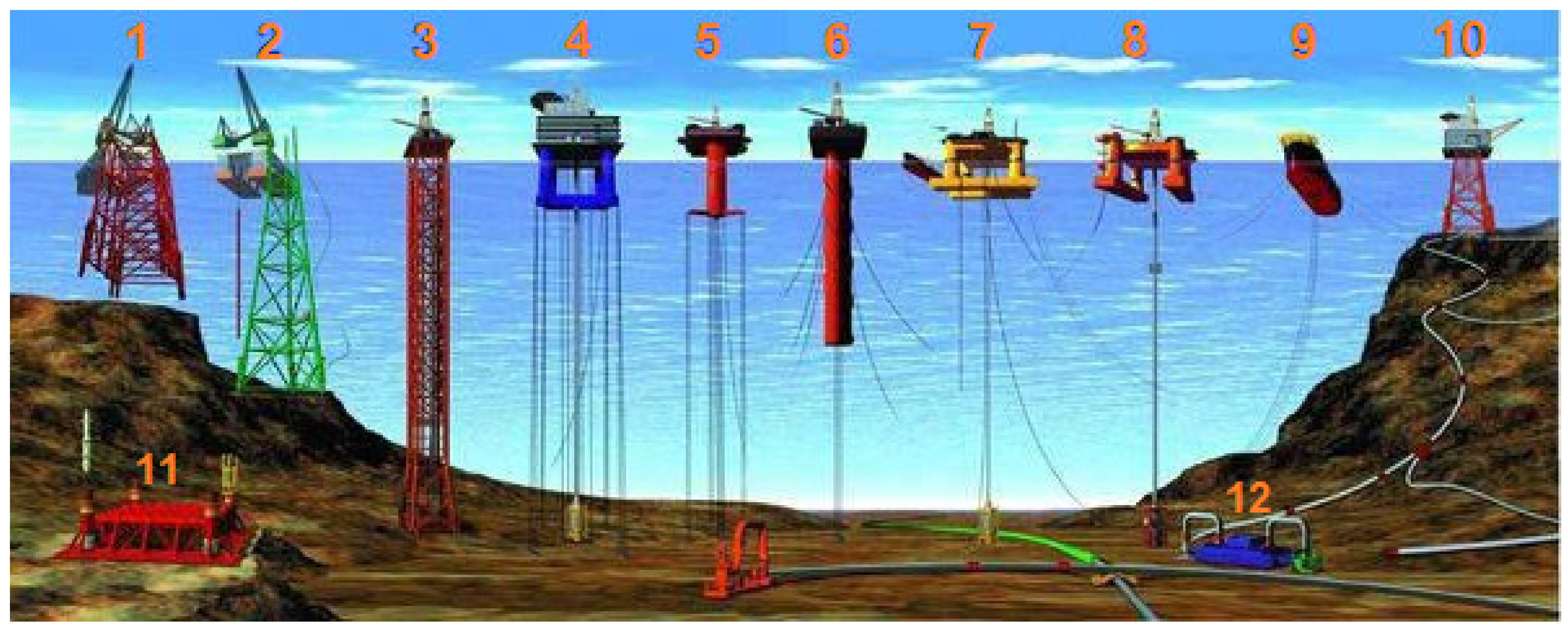
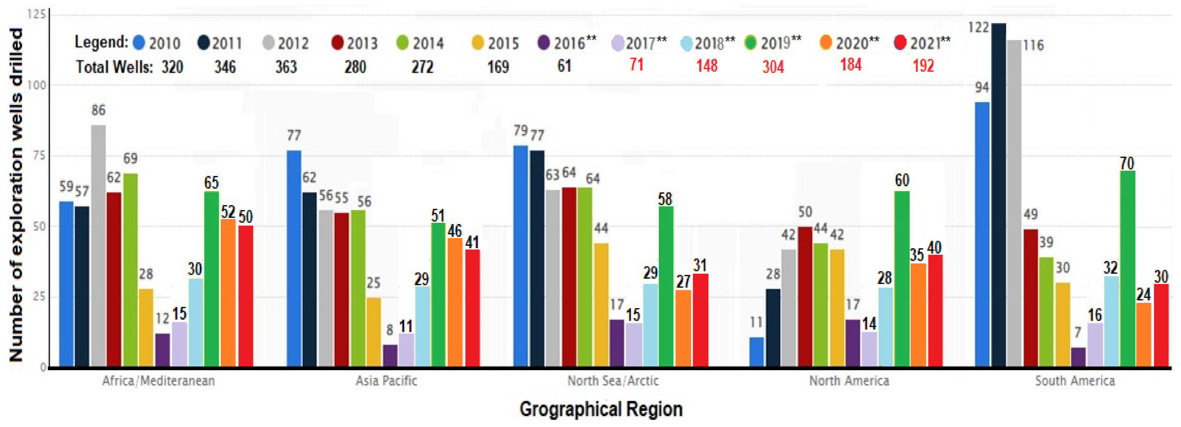
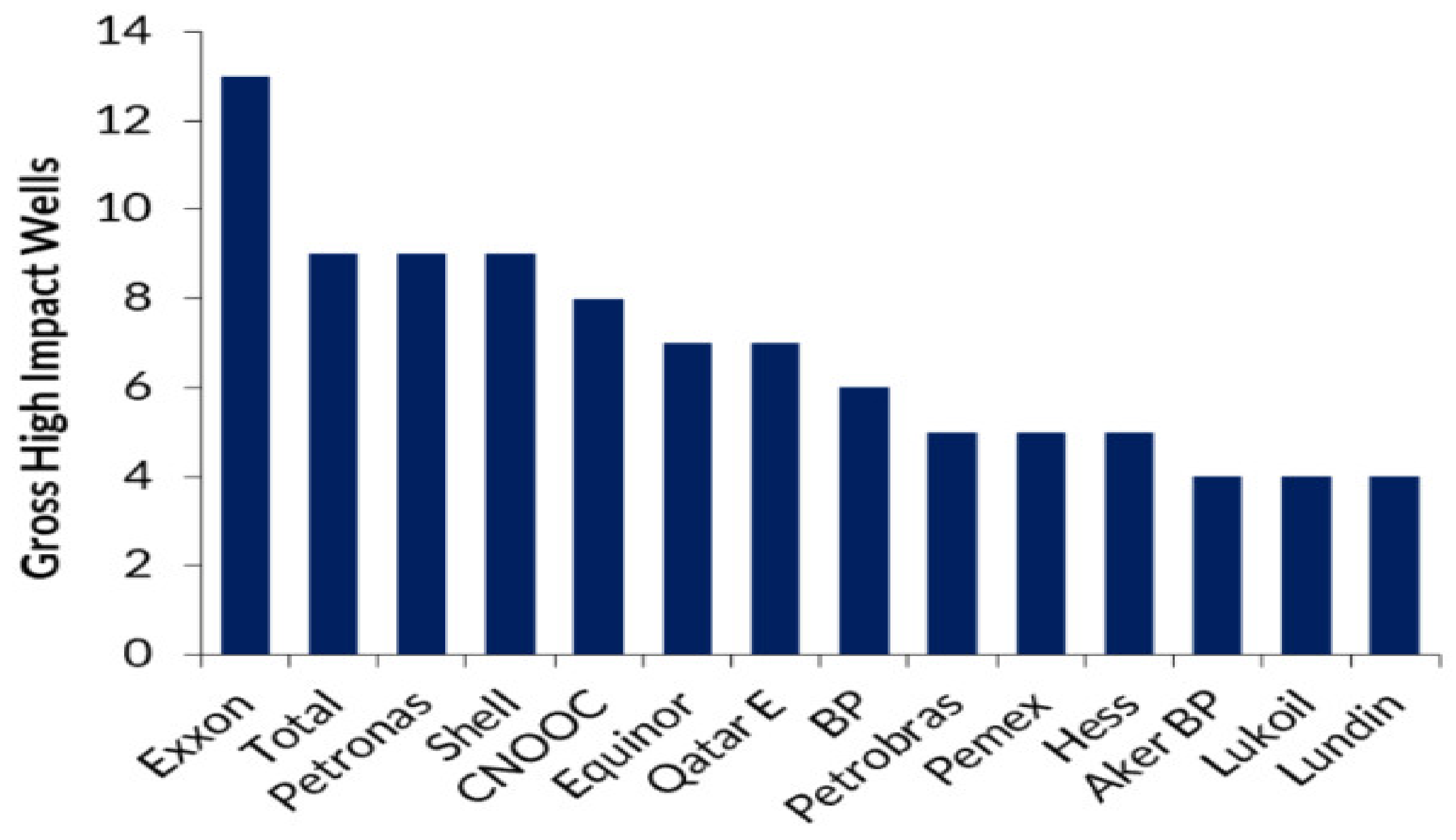
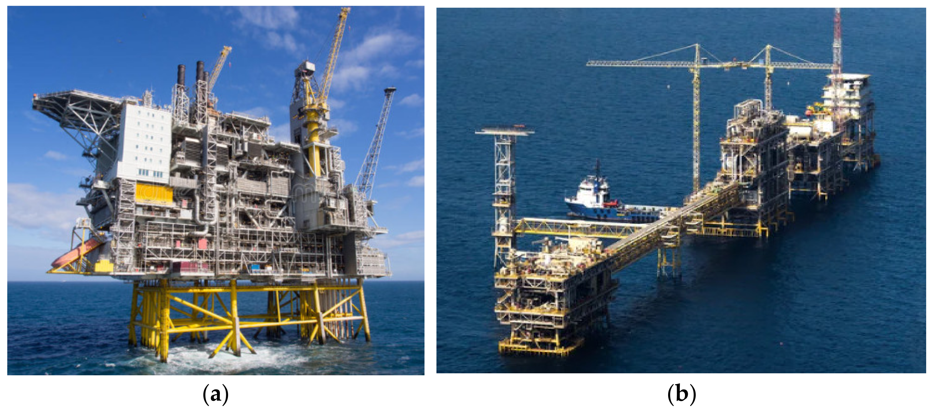
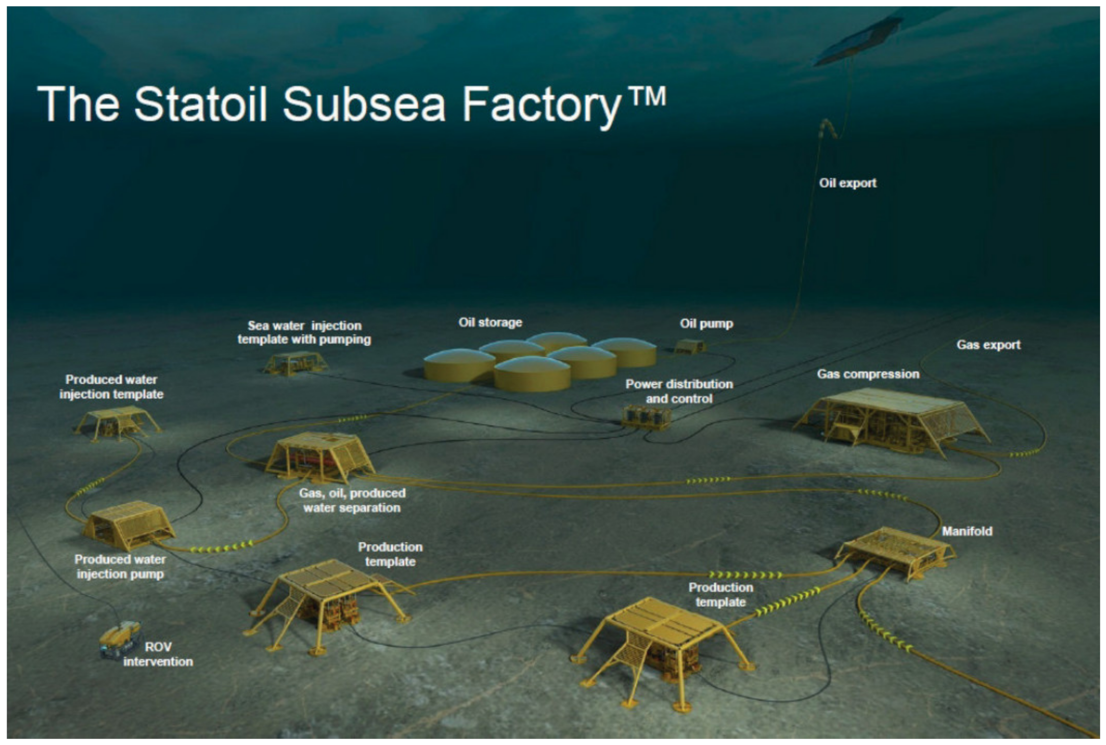
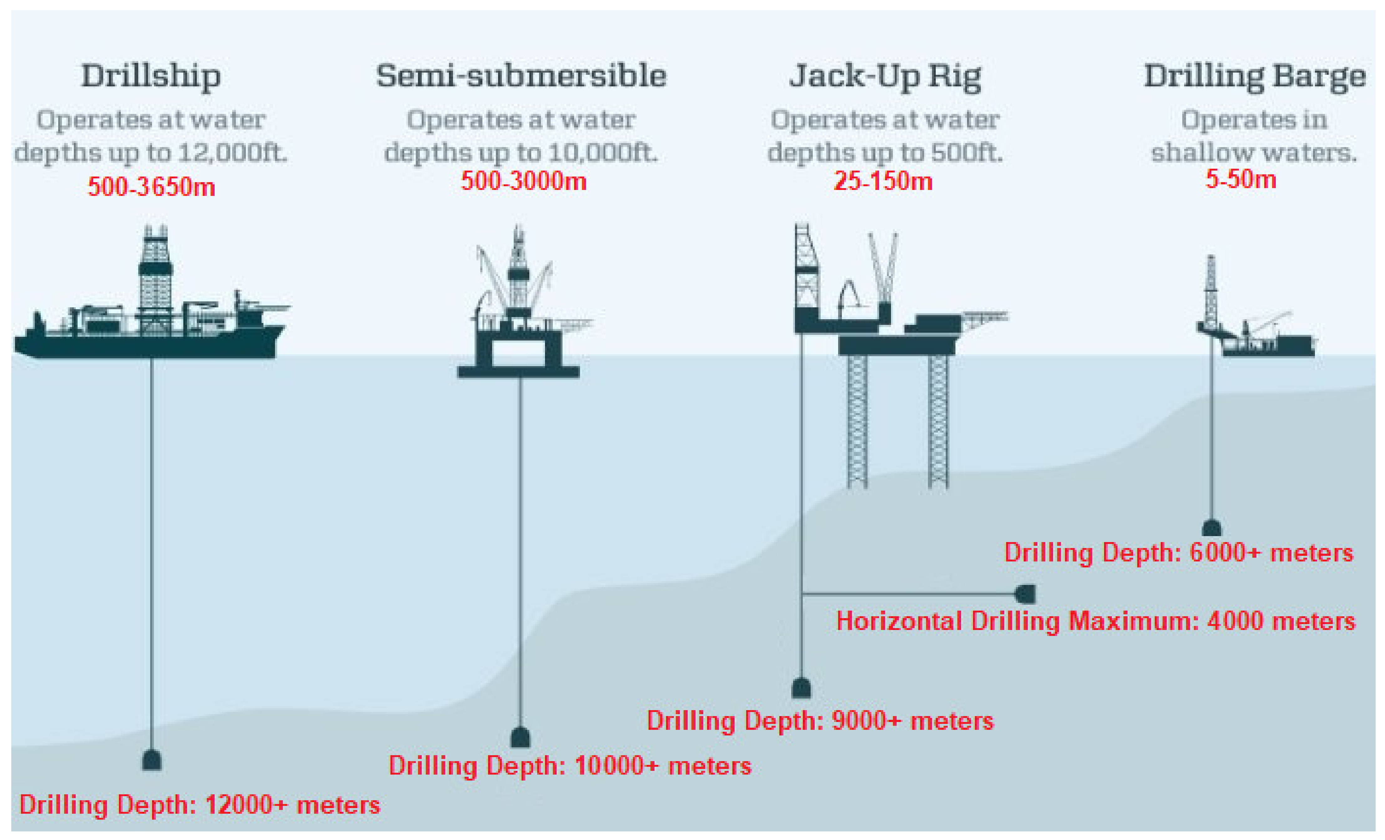
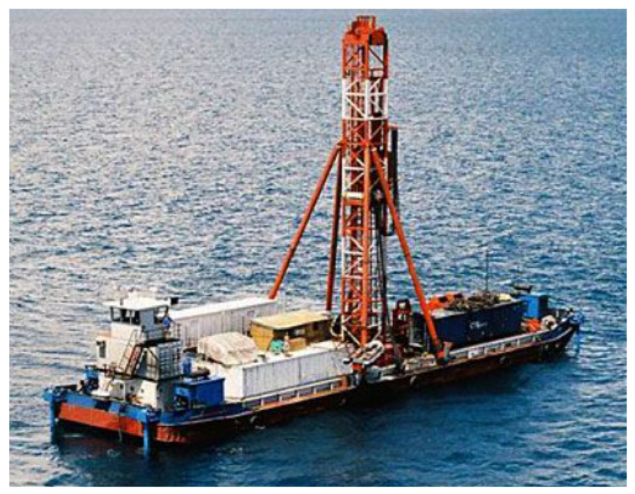
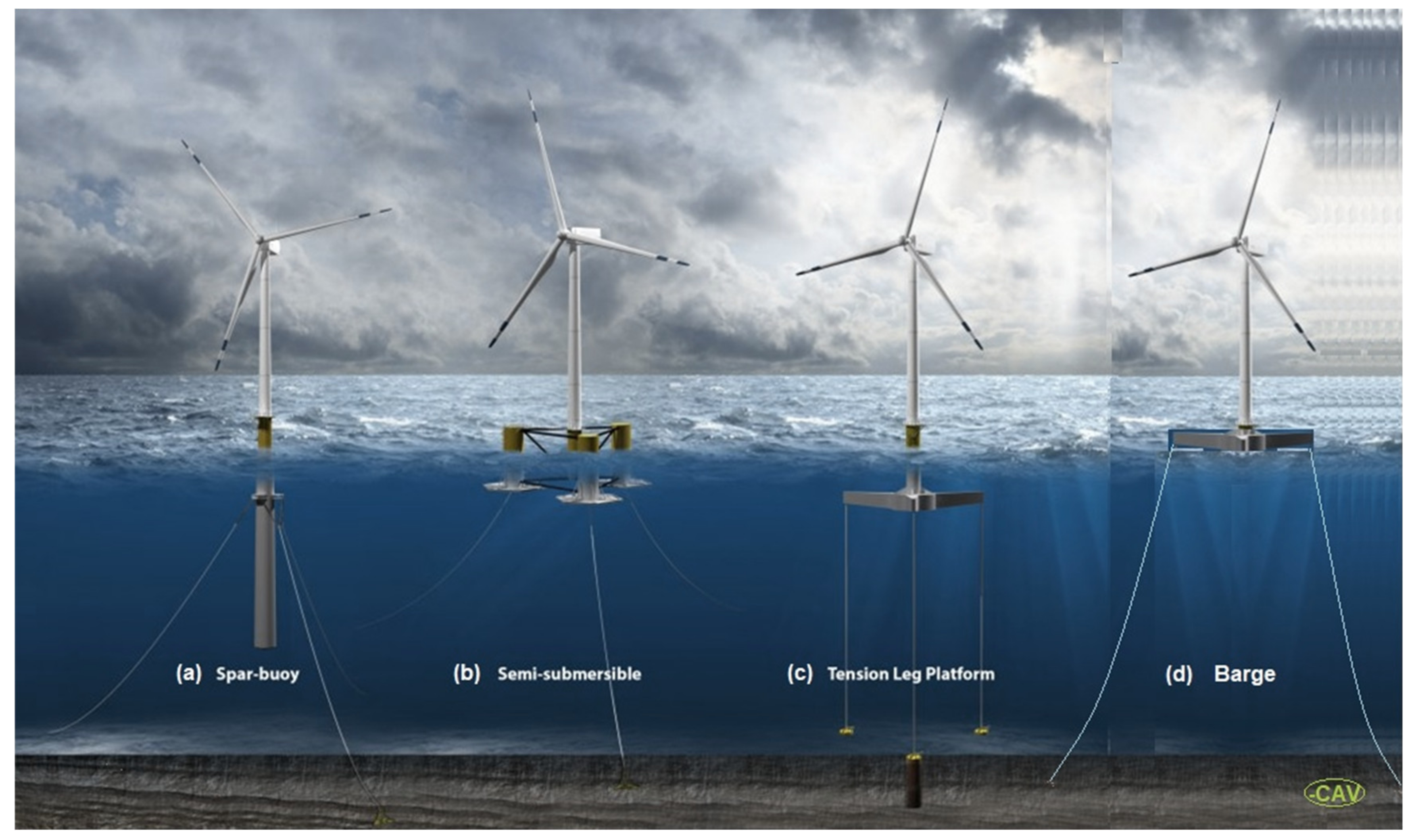
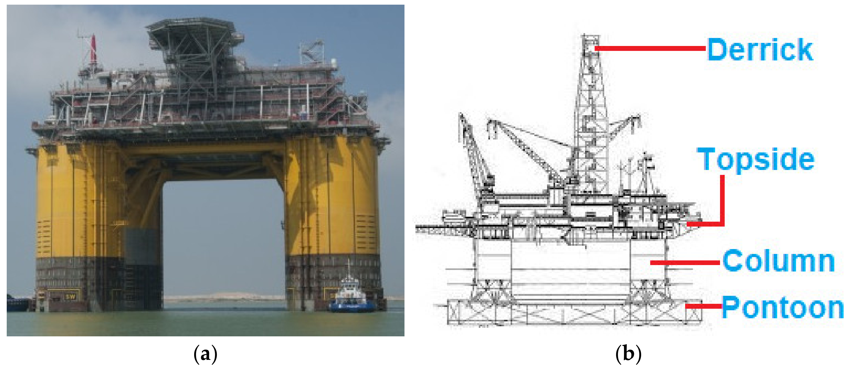
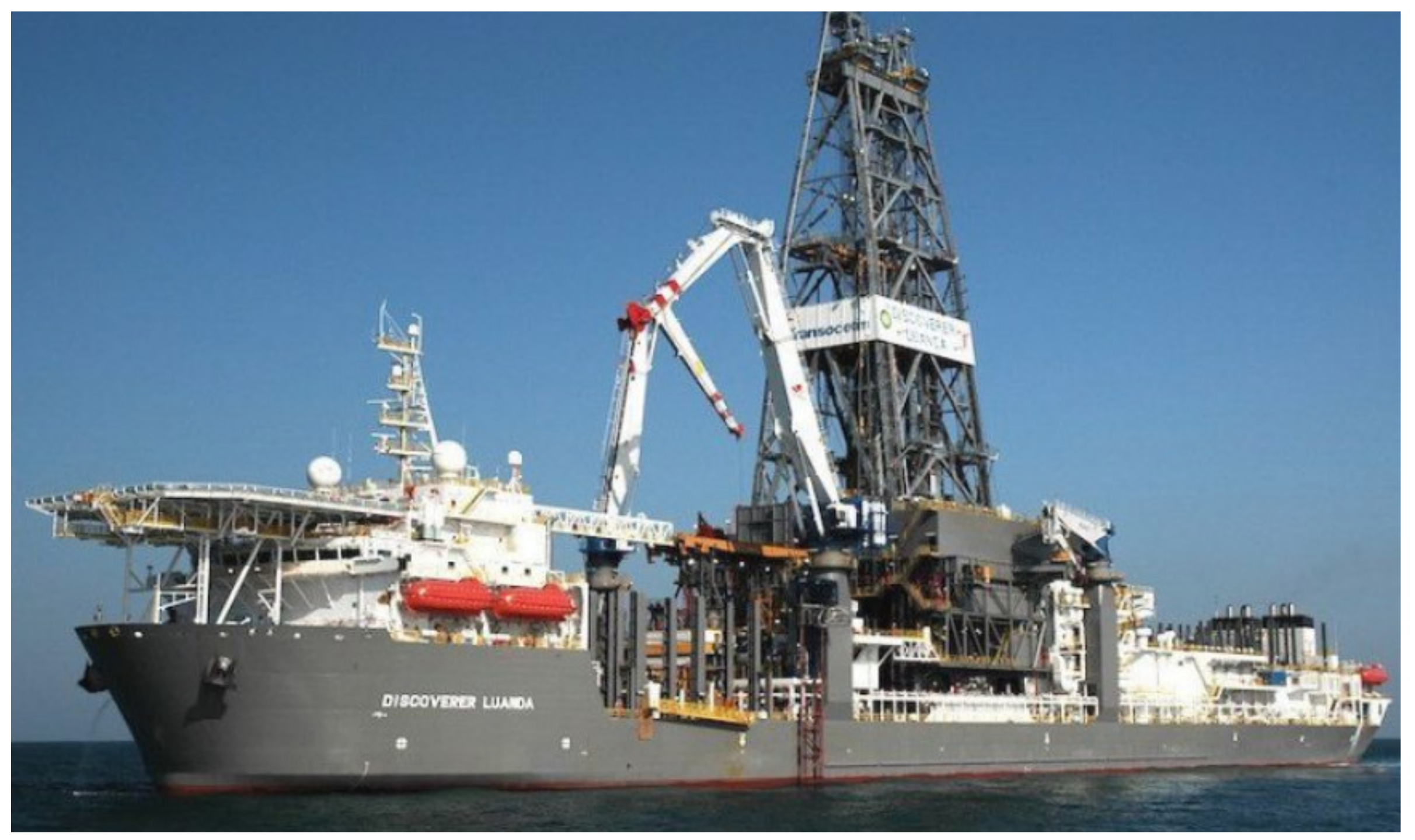
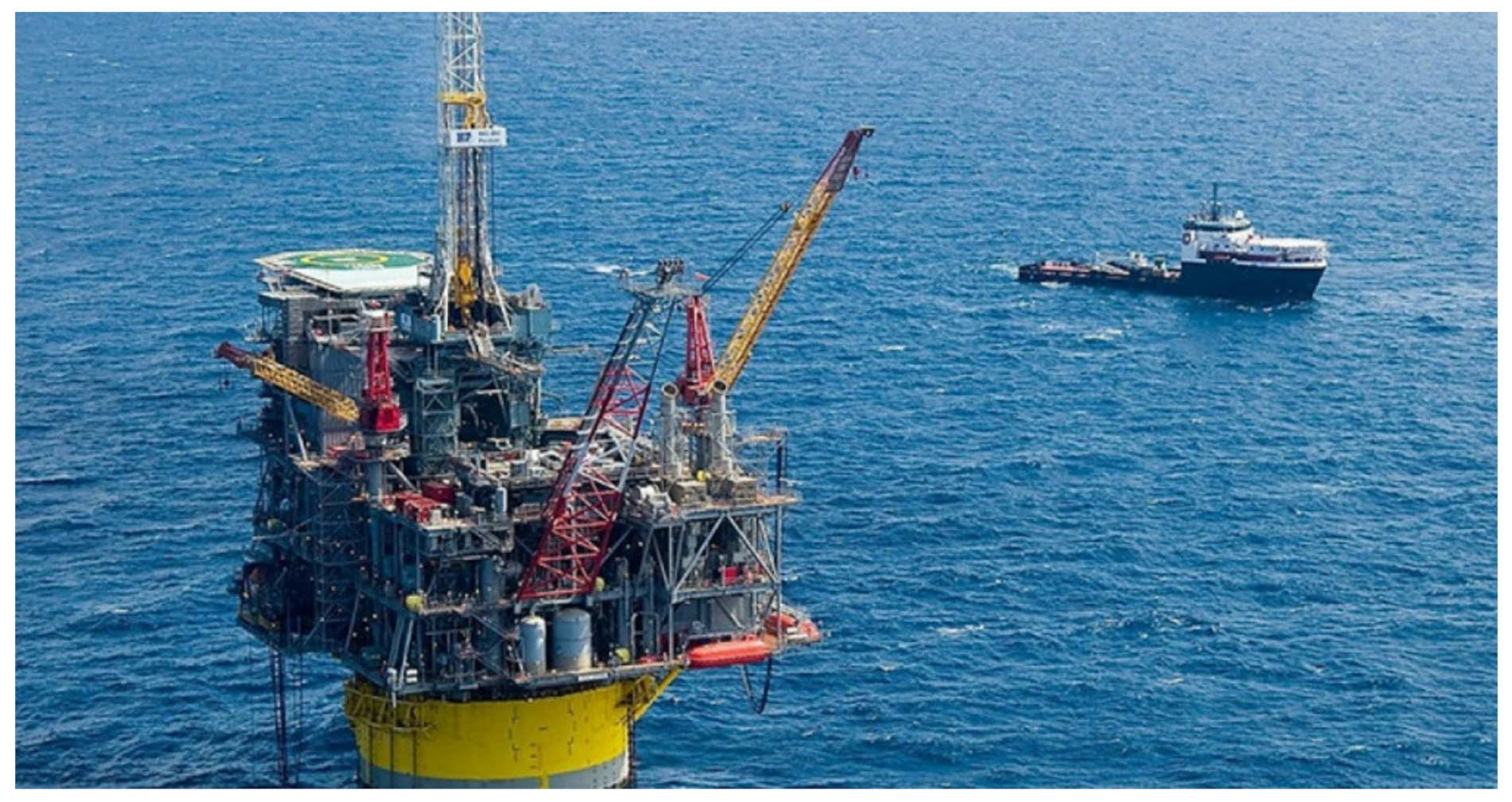
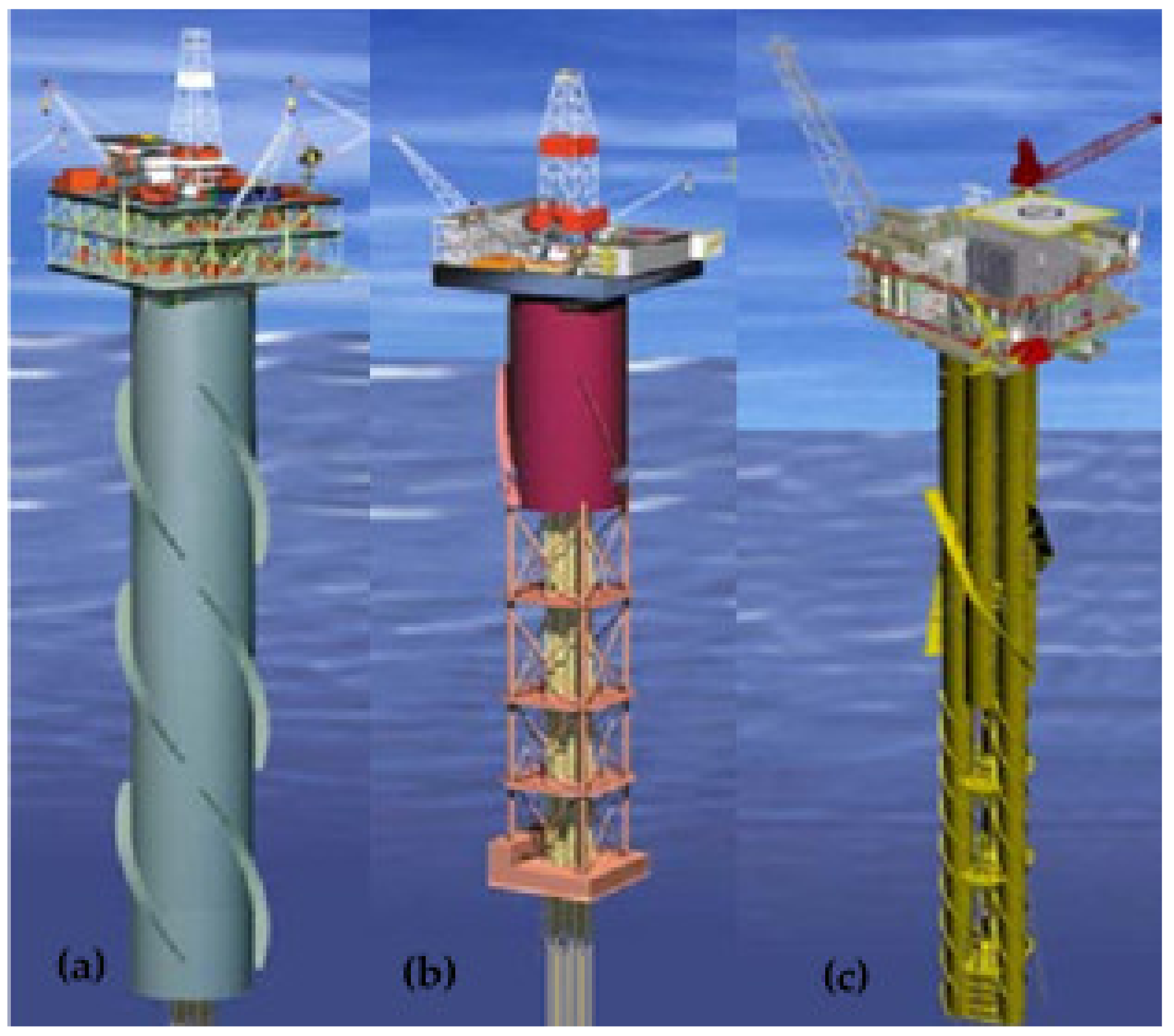
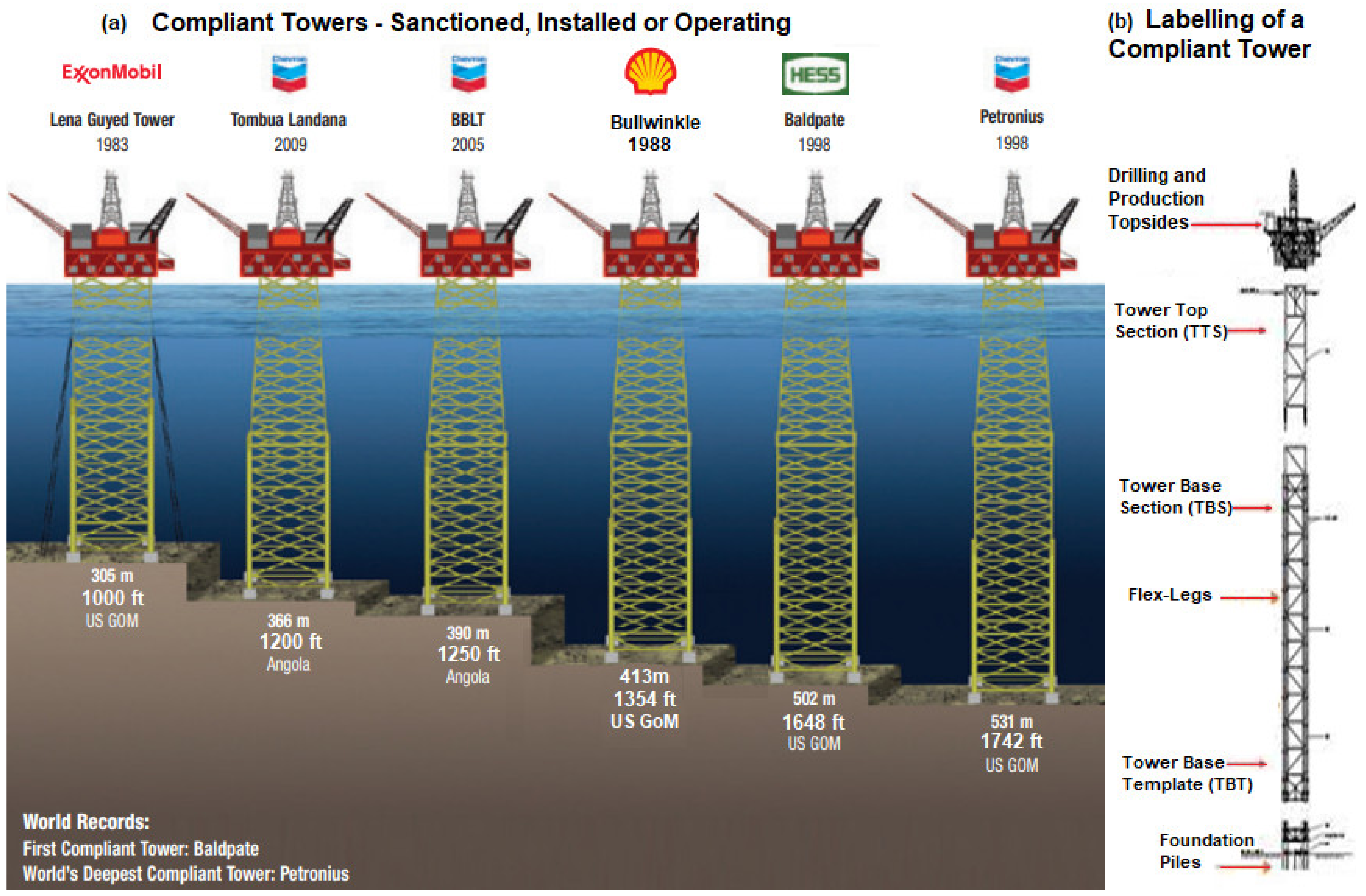
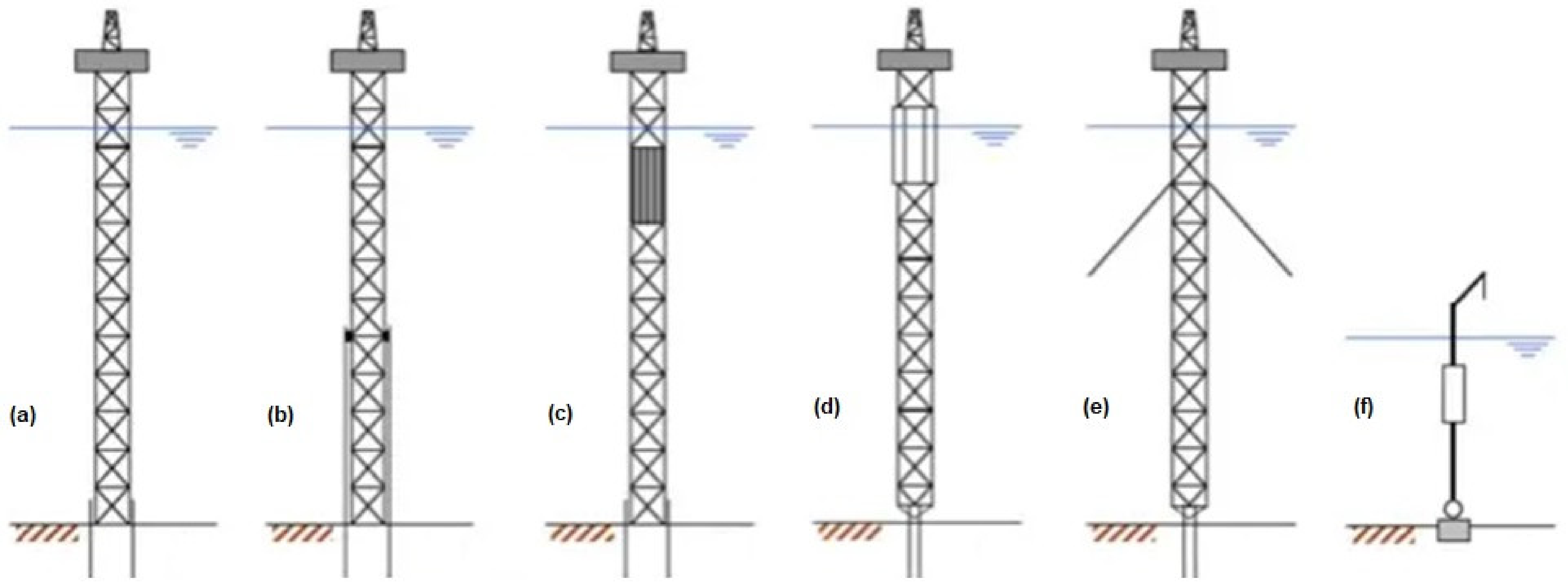
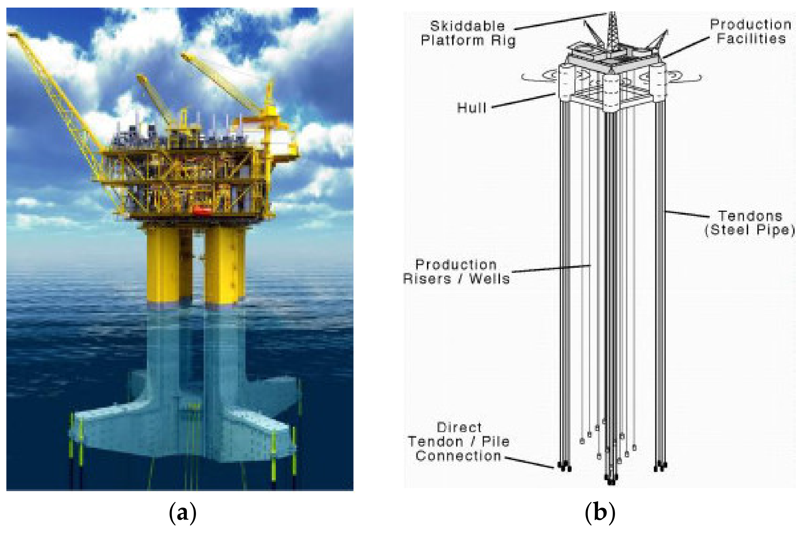
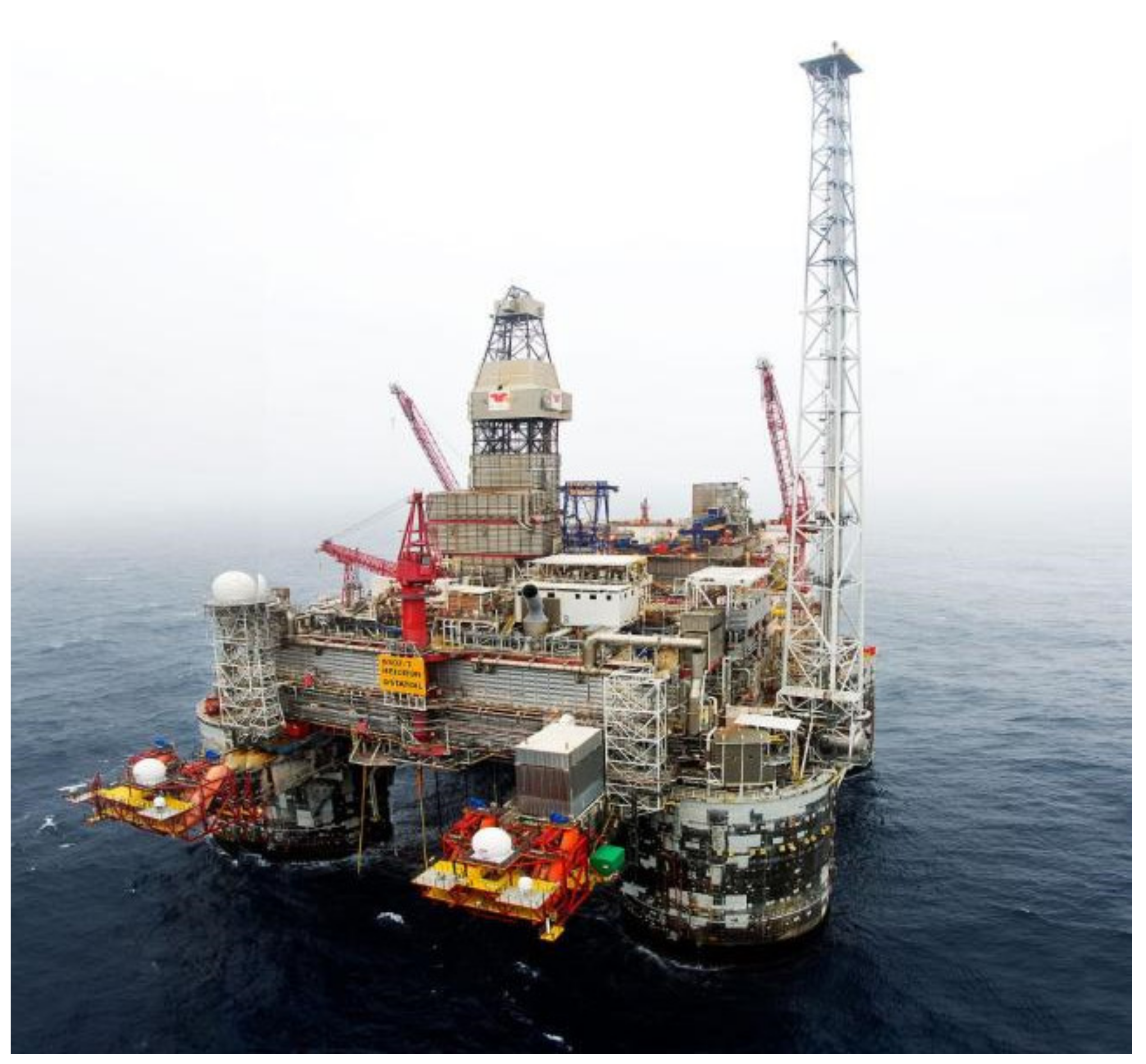
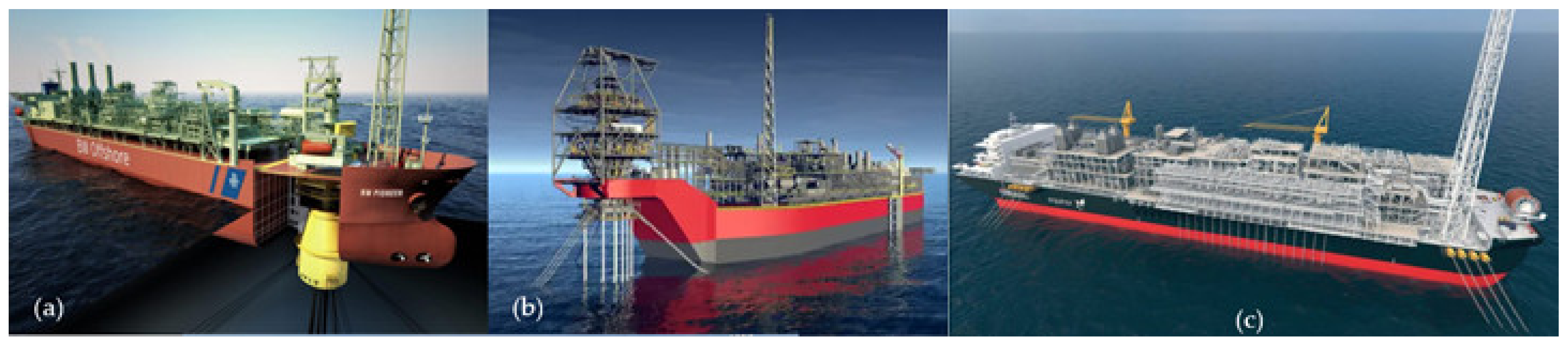
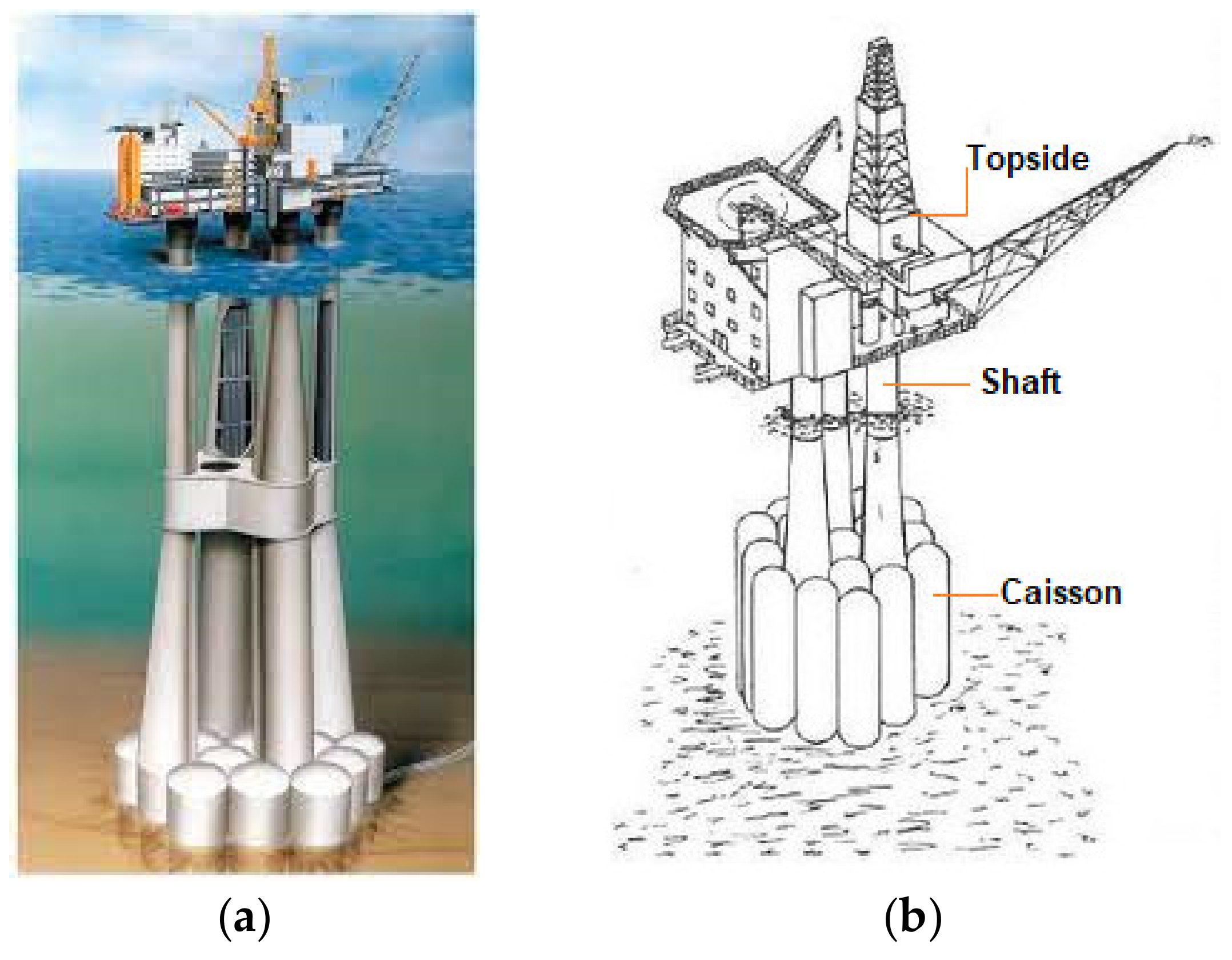
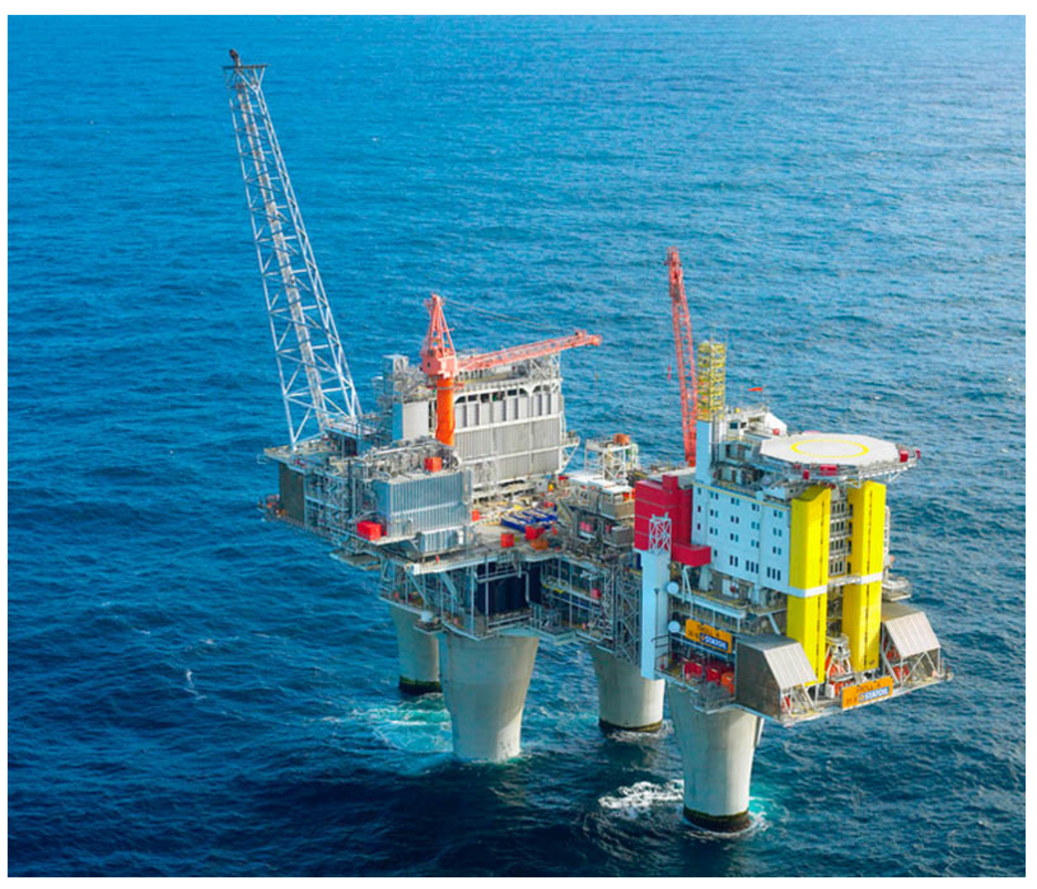
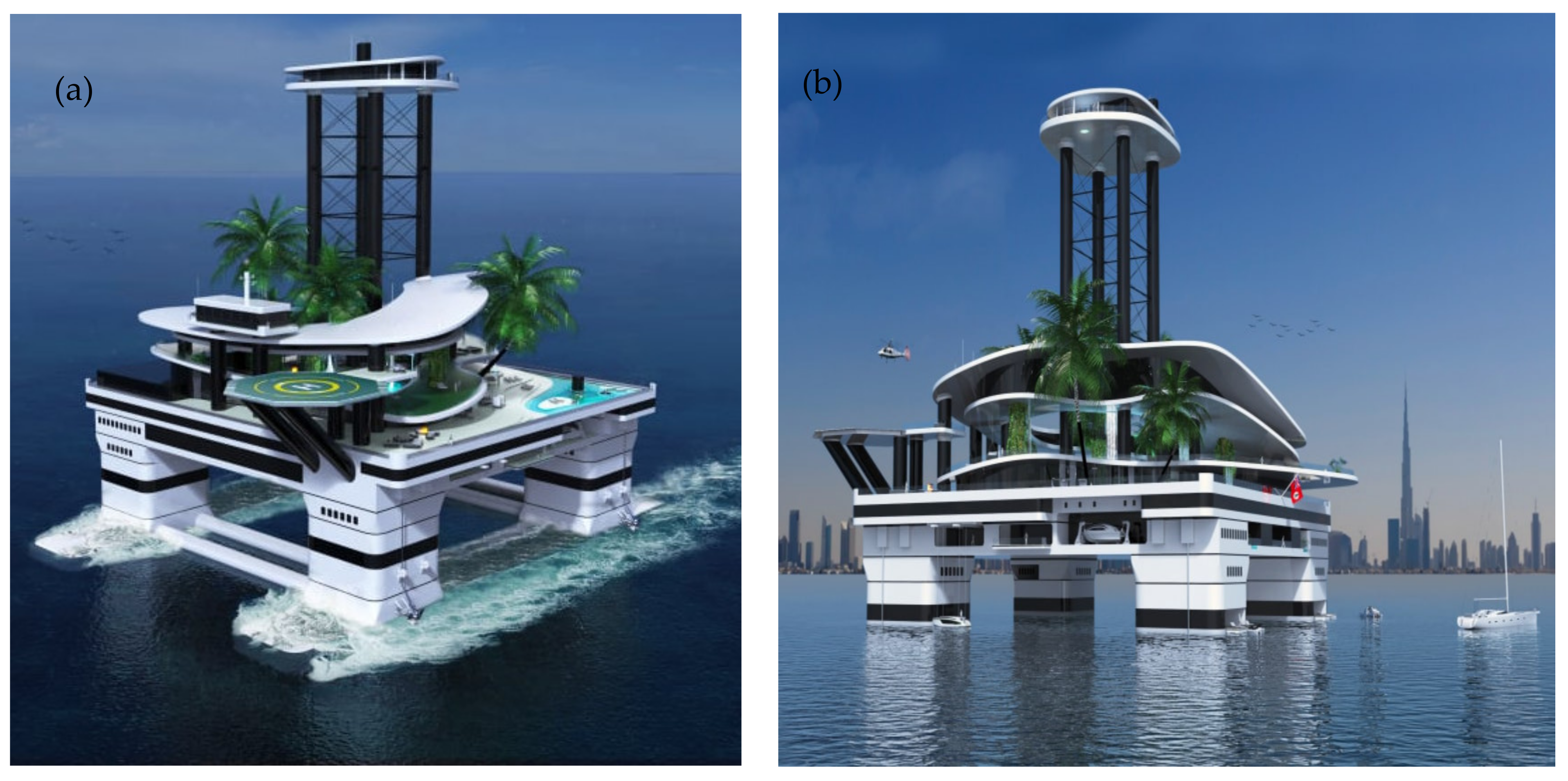
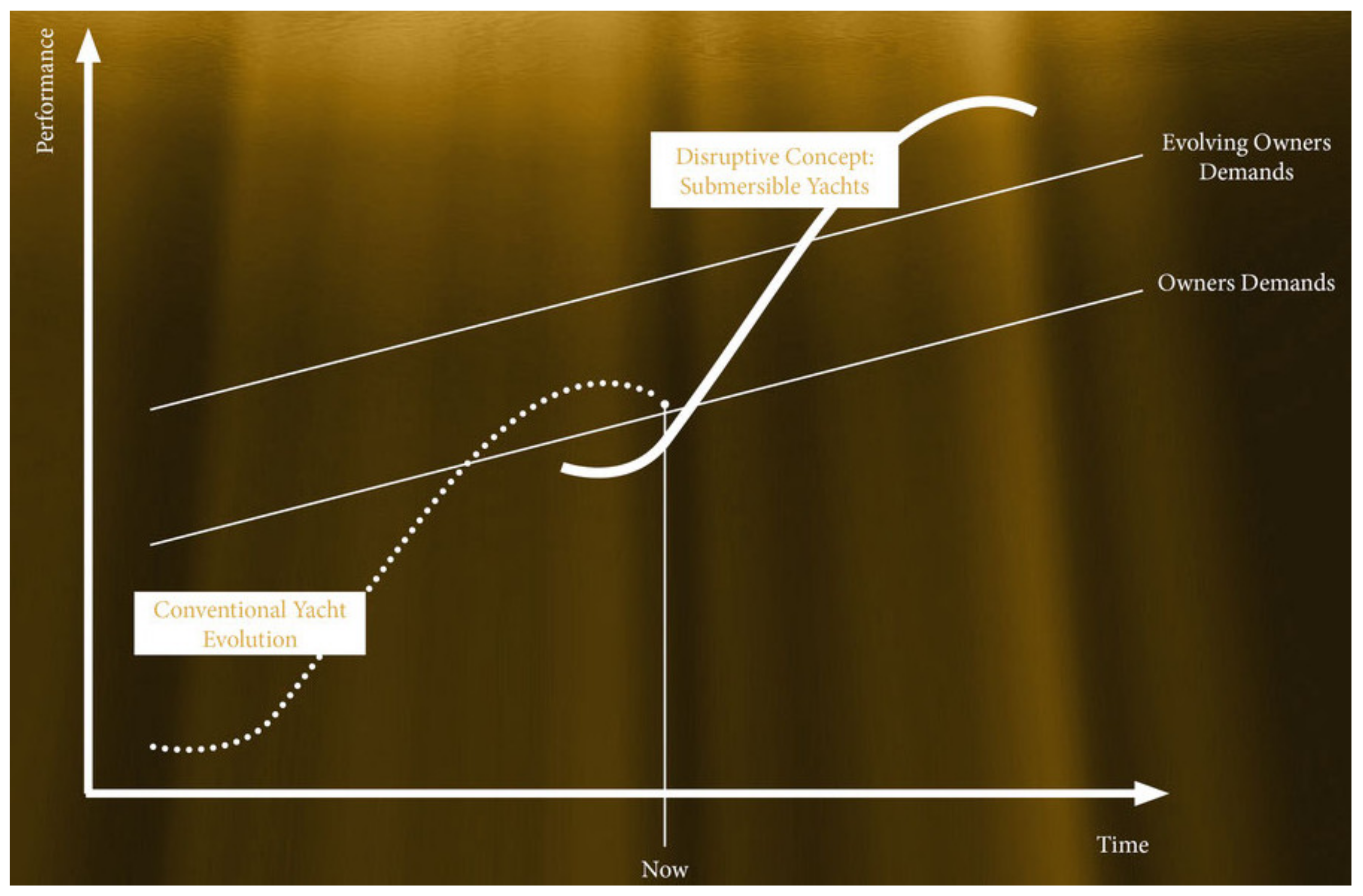
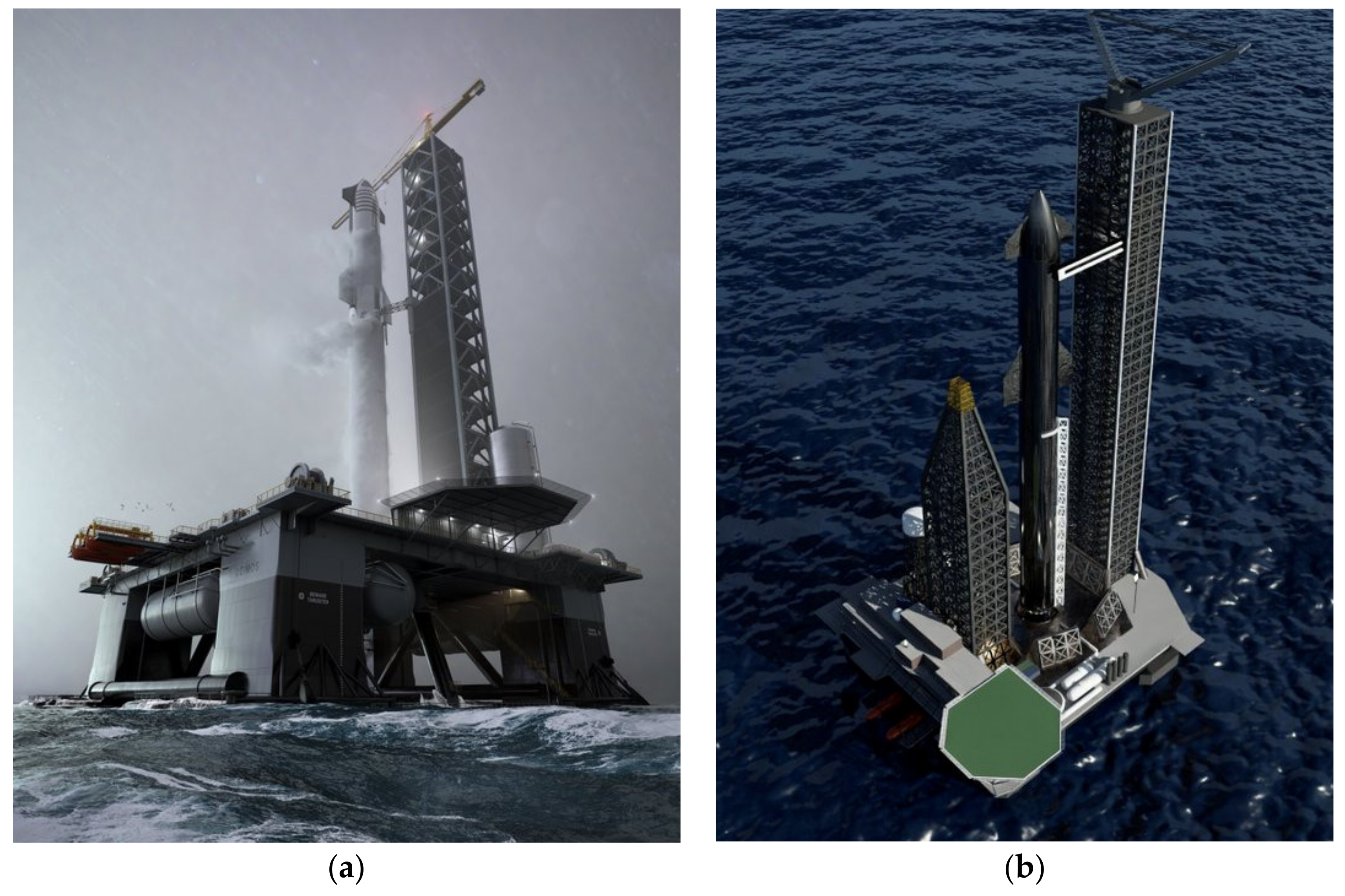
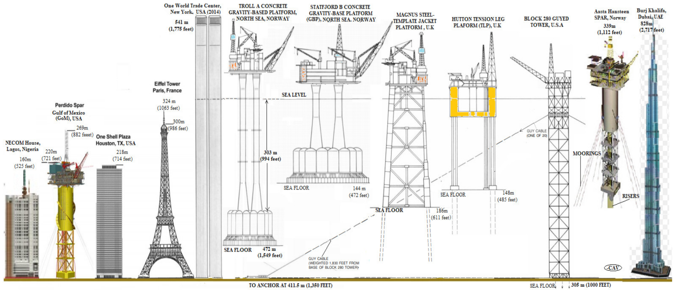
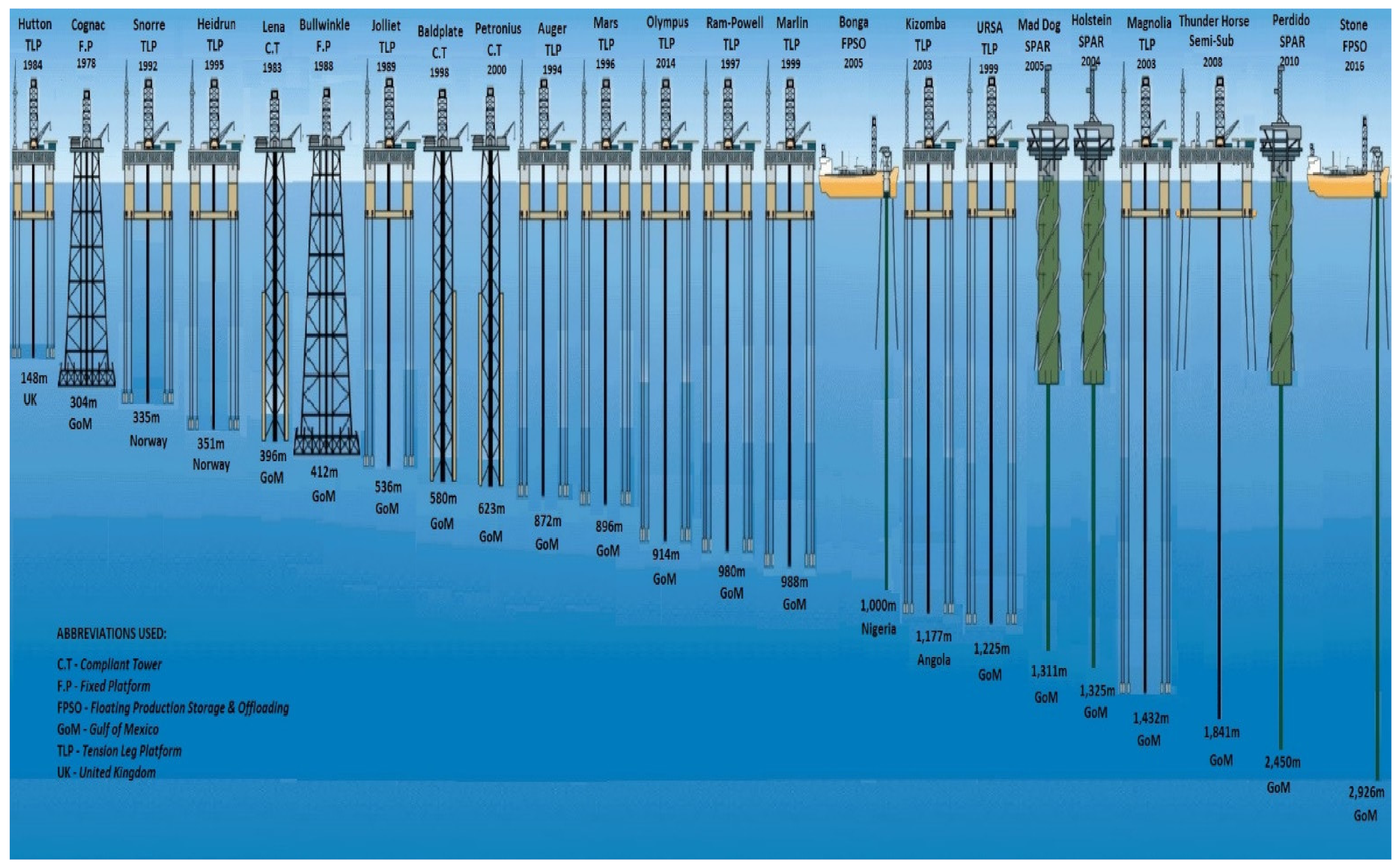
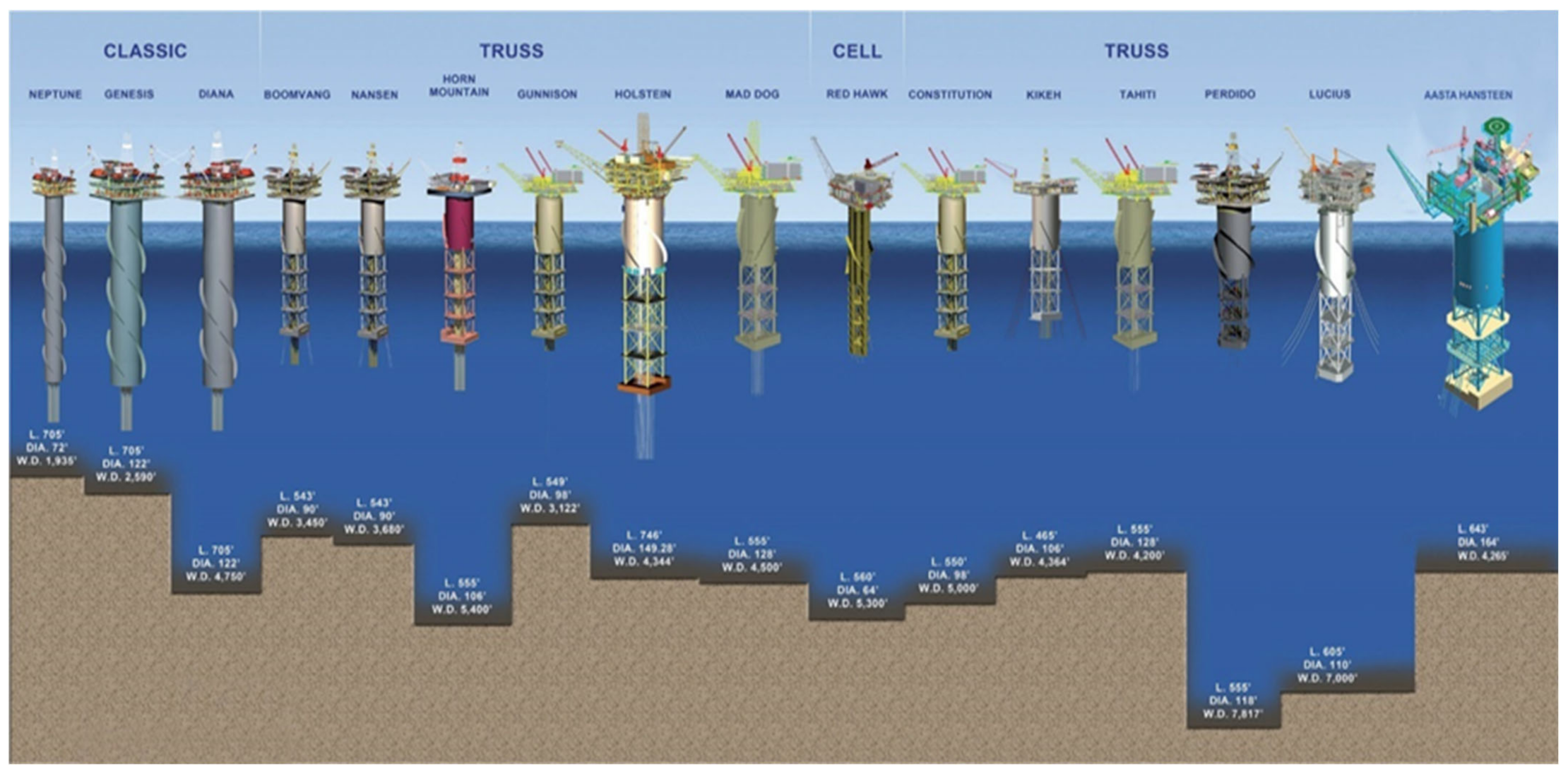
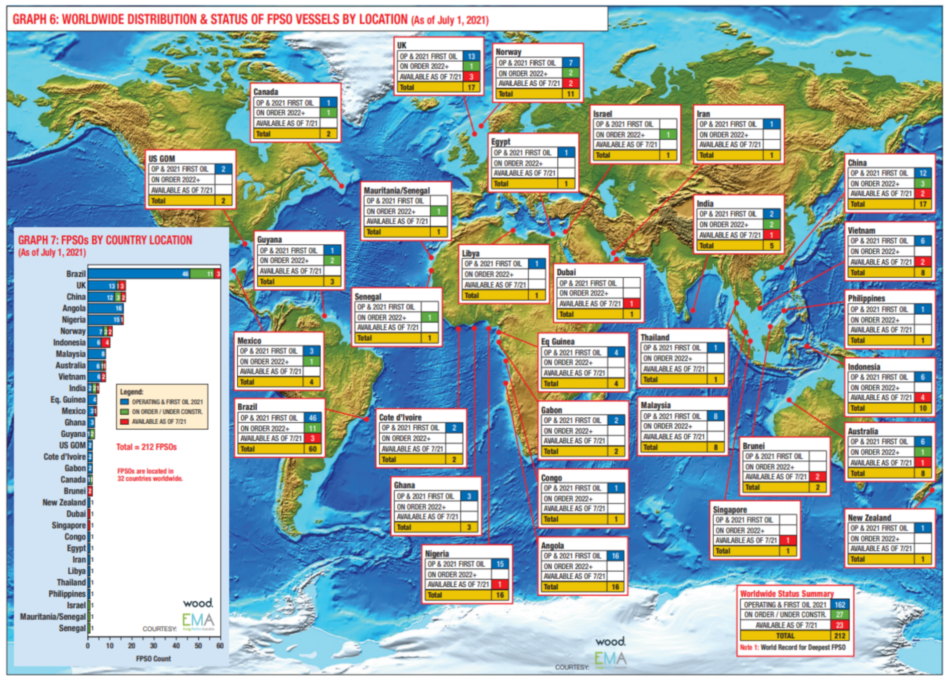
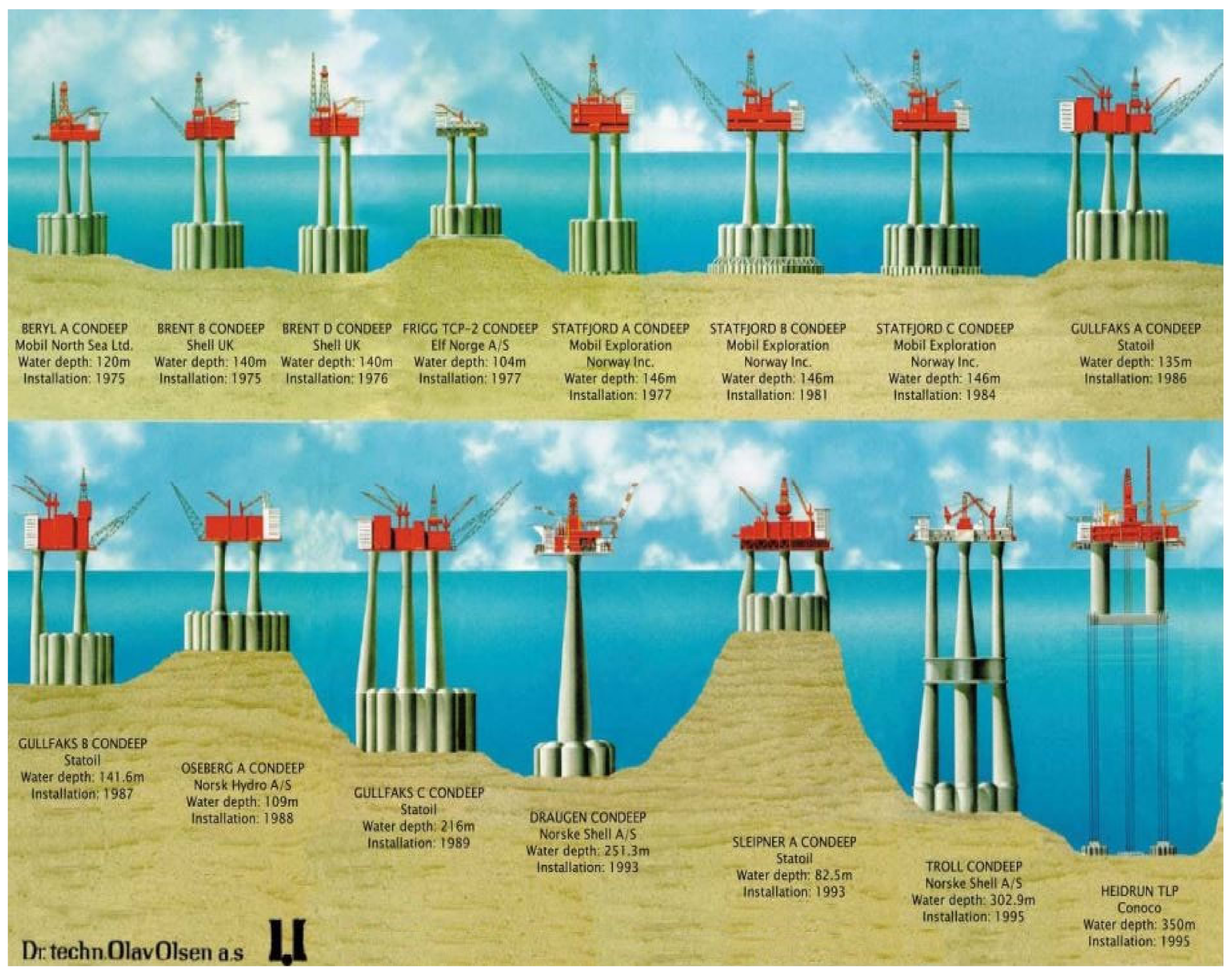
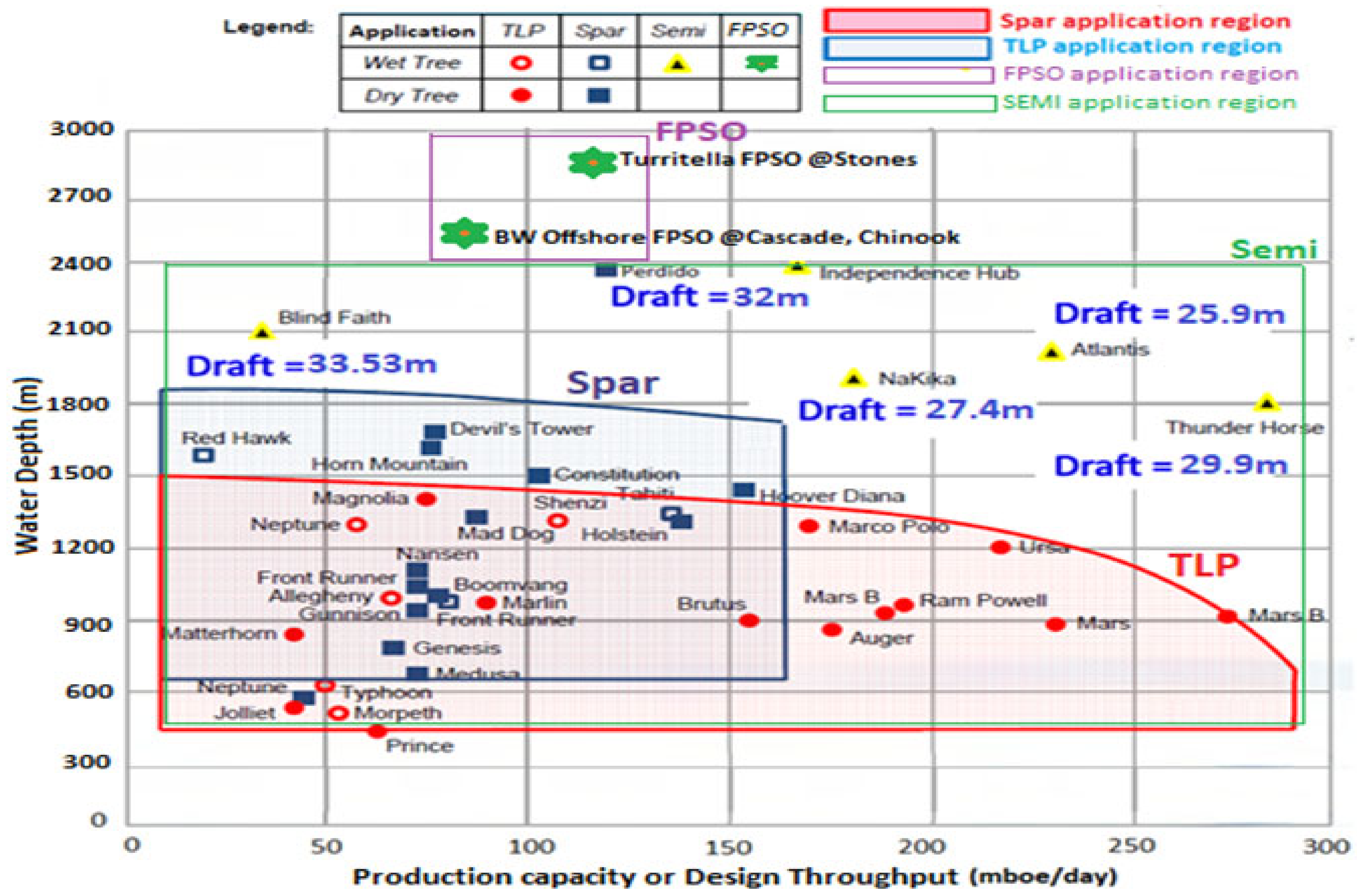
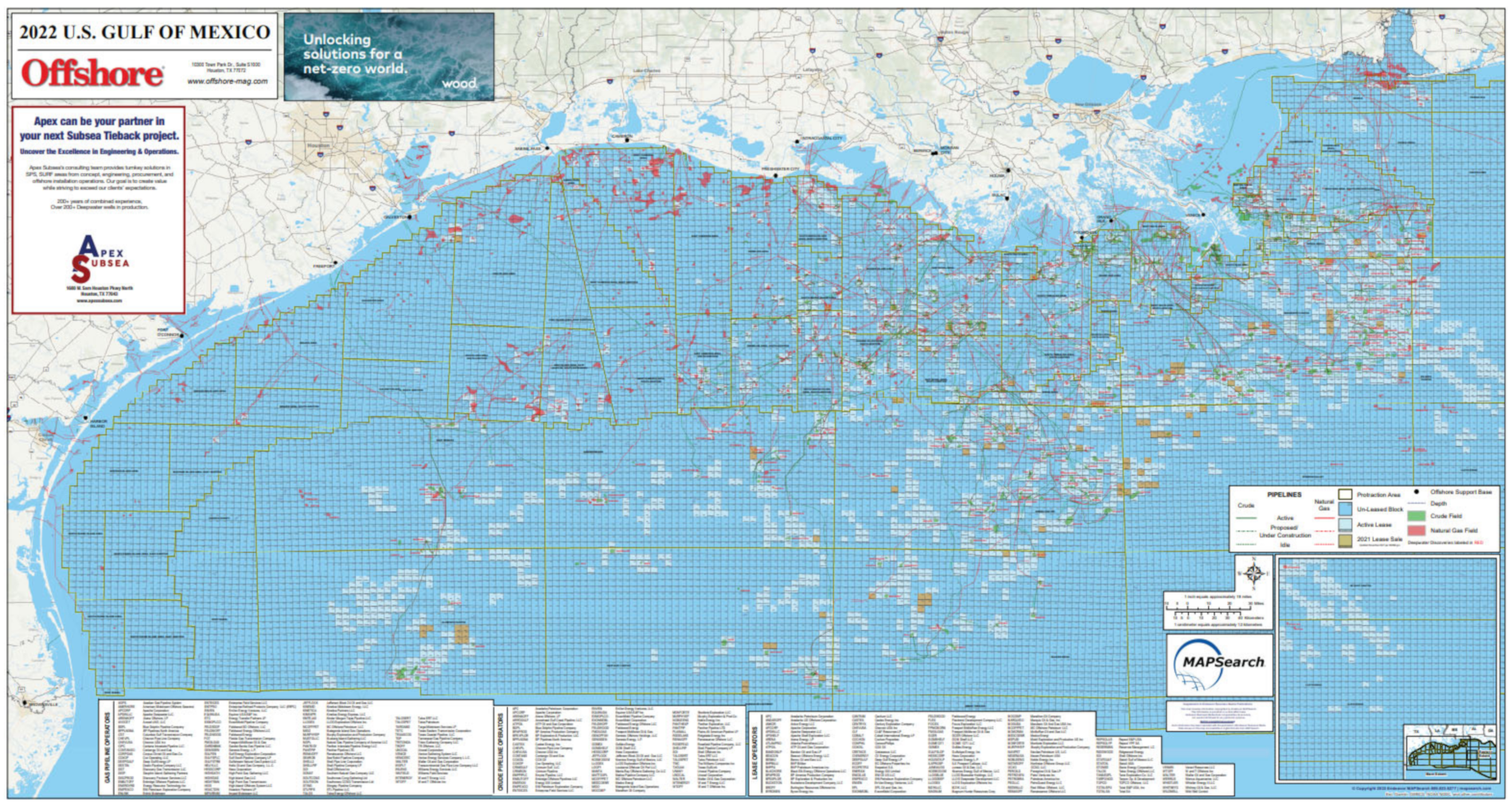
| Platform | Sidetrack Subsea Well | Sidetrack Dry Trees Well | Amount | Subsea Field |
|---|---|---|---|---|
| FPSO | 1 (2) | 2 (0) | 1 | 1 (1) |
| Mobile offshore production units (MOPU) | 6 (13) | -- -- | 1 | -- (2) |
| Semisubmersible | 32 (28) | 22 (16) | 9 | 6 (18) |
| Mini TLP | 17 (17) | 11 (16) | 5 | 1 (6) |
| Tension Leg Platform (TLP) | 51 (60) | 123 (150) | 10 | 8 (14) |
| Single Point Anchor Reservoir (SPAR) | 34 (43) | 133 (129) | 16 | 13 (18) |
| Fixed Platform (FP) | 47 (49) | 630 (449) | 50 | 49 (30) |
| Compliant towers (CT) | 3 (1) | 76 (46) | 3 | 4 (2) |
| AGGREGATE | 191 (213) | 997 (806) | 95 | 82 (91) |
| Key Parameters | Heavy Oil Fields | Oil Fields | Gas/Condensate Fields |
|---|---|---|---|
| Colder (heavy/complex fluids) | Cold transport | Cold flow | Sour/Acid gas issues |
| Colder (arctic environment) | Harsh environment | Under ice | Under ice |
| Deep water (deeper environment) | 2000 m | 3000 m | 3000 m |
| Longer power | 50 MW | 20 MW | 100 MW |
| Longer transport | 50 km | 200 km | 250 km |
| Name | Installation Year | Diameter | Tower Height | Capacity | Status |
|---|---|---|---|---|---|
| Hornsea 2 | 2002 | 167 m | 190 m | 1396 MW | Active |
| Burbo Bank Extension | 2017 | 164 m | 113 m | 800 MW | Active |
| Westermost Rough | 2014 | 154 m | 102 m | 600 MW | Active |
| Anholt | 2012 | 120 m | 82 m | 360 MW | Active |
| Horns Rev 2 | 2009 | 93 m | 68 m | 230 MW | Active |
| Nysted | 2003 | 82.4 m | 69 m | 230 MW | Active |
| Middelgrund | 2000 | 76 m | 64 m | 200 MW | Active |
| Vindeby | 1991 | 35 m | 35 m | 4.95 MW | Inactive |
| Generation | Timelines | Water Depth | |
|---|---|---|---|
| Meters (m) | Feet (ft) | ||
| First | Early 1960s | 200 m | about 600 ft |
| Second | 1969–1974 | 300 m | about 1000 ft |
| Third | Early 1980s | 500 m | about 1500 ft |
| Fourth | 1990s | 1000 m | about 3000 ft |
| Fifth | 1998–2004 | 2500 m | about 7500 ft |
| Sixth | 2005–2012 | 3000 m | about 10,000 ft |
| Seventh | 2013–2022 | >3000 m | over 10,000 ft |
| Platform | Water Depth (m) | Operator | Installation Year | Location |
|---|---|---|---|---|
| Appomattox | 2195 m | Shell | 2019 | GoM, USA |
| Thunder Horse PDQ | 1841 m | BP & ExxonMobil | 2010 | GoM, USA |
| Na Kika | 1829 m | Shell & BP | 2003 | GoM, USA |
| Atlantis PQ | 2134 m | BP & BHP | 2007 | GoM, USA |
| Argos /Mad Dog Phase 2 | 1311 m | BP | 2022 | GoM, USA |
| Vito | 1189 m | Shell | 2022 | GoM, USA |
| Delta House | 1370 m | LLOG | 2015 | GoM, USA |
| Platform | Water Depth (m) | Type | Length (ft) | Diameter (ft) | Operator | Installation Year | Location |
|---|---|---|---|---|---|---|---|
| Neptune SPAR | 1935 ft | Classic | 705 ft | 72 ft | Noble Energy | 1996 | GoM, USA |
| Medusa SPAR | 2223 ft | Truss | 586 ft | 94 ft | Murphy E&P | 2003 | GoM, USA |
| Front Runner SPAR | 3350 ft (1021 m) | Truss | 587 ft | 94 ft | Murphy E&P | 2004 | GoM, USA |
| Mad dog SPAR | 4500 ft (1311 m) | Truss | 555 ft | 128 ft | BP | 2005 | GoM, USA |
| Perdido SPAR | 7817 ft (2450 m) | Truss | 555 ft | 118 ft | Shell | 2010 | GoM, USA |
| Genesis SPAR | 2590 ft | Classic | 705 ft | 122 ft | Chevron USA | 1998 | GoM, USA |
| Hoover Diana DDCV SPAR | 4825 ft | Classic | 705 ft | 122 ft | Exxon Mobil | 2000 | GoM, USA |
| Boomvang SPAR | 3450 ft | Truss | 543 ft | 90 ft | Anadarko | 2002 | GoM, USA |
| Nansen SPAR | 3680 ft | Truss | 543 ft | 90 ft | Anadarko | 2001 | GoM, USA |
| Horn Mountain | 5400 ft | Truss | 555 ft | 106 ft | Anadarko | 2002 | GoM, USA |
| Gunnison | 3122 ft | Truss | 549 ft | 3122 ft | Anadarko | 2003 | GoM, USA |
| Holstein | 4344 ft | Truss | 746 ft | 149.28 ft | Anadarko | 2004 | GoM, USA |
| Constitution SPAR | 5000 ft | Truss | 550 ft | 98 ft | Anadarko | 2005 | GoM, USA |
| Kikeh SPAR | 4364 ft | Truss | 465 ft | 106 ft | Murphy | 2007 | Malaysia |
| Tahiti SPAR | 4200 ft | Truss | 555 ft | 128 ft | Chevron USA | 2008 | GoM, USA |
| Lucius SPAR | 7000 ft | Truss | 605 ft | 110 ft | Anadarko | 2014 | GoM, USA |
| Devils Tower SPAR | 5610 ft | Truss | 586 ft | 94 ft | Eni US | 2004 | GoM, USA |
| Heidelberg SPAR | 5300 ft | Truss | 605 ft | 110 ft | Anadarko | 2016 | GoM, USA |
| Gulfstar SPAR | 4600 ft | Classic | 584 ft | 85 ft | Hess | 2014 | |
| Aasta Hansteen SPAR | 4265 ft | Truss | 643 ft | 164 ft | Equinor | 2019 | North Sea, Norway |
| Red Hawk SPAR | 5300 ft | Cell | 560 ft | 64 ft | Kerr McGee & Devon Energy | 2004 | GoM |
| Platform | Water Depth, m (ft) | Operator | Installation Year | Location |
|---|---|---|---|---|
| Amberjack | 314 m (1100 ft) | BP | 1991 | USA |
| Pompano | 393 m (1290 ft) | BP/Stone Energy | 1994 | USA |
| Heritage | 326 m (1070 ft) | Exxon | 1993 | USA |
| Harmony | 366 m (1201 ft) | Exxon | 1993 | USA |
| Virgo | 344 m (1129 ft) | Elf/W & T Energy | 2000 | USA |
| Cyrus | 134 m (440 ft) | Chevron USA | 2002 | USA |
| Salsa | 211 m (693 ft) | Shell | 1998 | USA |
| Ligera | 282 m (924 ft) | Fieldwood SD | 1982 | USA |
| Tequila | 201 m (660 ft) | Fieldwood SD | 1984 | USA |
| Snapper | 263 m (863 ft) | Fieldwood SD | 1985 | USA |
| Tarantula | 148 m (484 ft) | Fieldwood Energy | 2004 | USA |
| Cerveza | 285 m (935 ft) | Fieldwood SD | 1981 | USA |
| Coelacanth | 361.5 m (1186 ft) | Water Oil & Gas | 2015 | USA |
| Simba | 203 m (667 ft) | Ankor Energy | 2005 | USA |
| Spirit | 220 m (722 ft) | Fieldwood Energy | 1998 | USA |
| Enchilada | 215 m (705 ft) | Shell | 1997 | USA |
| Spect. Bid | 165 m (541 ft) | Flextrend Development | 1995 | USA |
| Phar Lap | 205 m (673 ft) | Flextrend Development | 1995 | USA |
| Alabaster | 145 m (476 ft) | Energy XXI GOM | 1991 | USA |
| Corrla | 189 m (619 ft) | Eni US | 1992 | USA |
| Pimento | 219.8 m (721 ft) | Triton Gathering | 1993 | USA |
| Tick | 219.5 m (720 ft) | Chevron USA | 1991 | USA |
| Lobster | 236 m (775 ft) | EnVen Energy Ventures | 1994 | USA |
| Marquette | 184 m (604 ft) | MC Offshore Petroleum | 1989 | USA |
| Boxer | 229 m (750 ft) | Shell Oil | 1988 | USA |
| Boxer | 229 m (750 ft) | Whistler Energy II | 1986 | USA |
| Boubon | 130 m (428 ft) | Fieldwood Energy | 1978 | USA |
| East Belumut A | 73 m (240 ft) | Newfield | 2008 | Malaysia |
| Agbara | 70 m (230 ft) | Agip Energy | 2000 | Nigeria |
| Amenam | 40 m (131 ft) | TotalFinaElf | 2003 | Nigeria |
| Litchendjili | 30 m (98 ft) | Eni Congo | 2015 | Congo |
| Dong Fang 13-2 | 70 m (230 ft) | Offshore Oil Eng. Co. | China | |
| Lu Feng | 241 m (791 ft) | Offshore Oil Eng. Co. | 2021 | China |
| CaNgu Vang | 113 m (371 ft) | Hoan Vu Joint Oper. Co. (HVJOC) | 2008 | Vietnam |
| Annamaria B | 59 m (194 ft) | Eni E &P | Italy | |
| Erskine jacket | 90 m (295 ft) | Texaco NS UK | 1997 | UK |
| West Franklin | 90 m (295 ft) | Elf Exploration | 2011 | UK |
| Tiffany field | 126 m (413 ft) | Agip UK | 1993 | UK |
| Zuluf field | 40 m (131 ft) | Saudi Aramco | 2020 | Saudi Arabia |
| Platform | Water Depth (m) | Operator | Installation Year | Location |
|---|---|---|---|---|
| Valhall flank West WHP | 70 m (230 ft) | BP | 1982 | Norway |
| Huldra Phase 1 WHP | 125 m (410 ft) | Statoil | 2001 | Norway |
| Eldfisk 2/4 B WHP | 70 m (230 ft) | ConocoPhillips | 1979 | Norway |
| Blacktip WHP | 50 m (164 ft) | Eni | 2006 | Australia |
| Elgin B WHP | 90 m (295 ft) | Elf Exploration | 2012 | UK |
| Platform Parameters | Petronius | Lena Guyed Tower | Baldpate | Bullwinkle (Fixed) | Cognac | Benguela-Belize Lobito-Tomboco (BBLT) | Tombua-Landana |
|---|---|---|---|---|---|---|---|
| Location | GoM | GoM | GoM | GoM | GoM | Angola | Angola |
| Installation Year | 1997 | 1983 | 1998 | 1988 | 1978 | 2006 | 2009 |
| Design Type | Type ‘b’ | Type ‘e’ | Type ‘a’ | Type ‘a’ | Type ‘a’ | Type ‘e’ | Type ‘e’ |
| Operator | Chevron | ExxonMobil | Hess | Shell | Shell | Chevron | Chevron |
| Natural Period (s) | 33 | 28 | ~30 | ~30 | ~30 | ~29 | ~28 |
| Wave height Hs (m) | 22.49 | 12.5 | 18.2 | 18.2 | 21.34 | 8.84 | 8.84 |
| Water Depth, (m) | 535 m | 305 m | 503 m | 413 m | 314 m | 390 m | 366 m |
| Topside weight, (tons) | 8800 | 9500 | 9000 | 2033 | 14,000 | 43,500 | 36,000 |
| Structure weight, (tons) | 43,000 | 23,400 | 28,900 | 49,375 | 59,000 | 49,800 | 56,400 |
| Well slot | 21 | 21 | 19 | 60 | 62 | 40 | 46 |
| Base Dimension (m) | 33.53 × 33.53 | 37 × 37 | 42.67 × 42.67 | 148 × 124 | 122 × 116 | 33.53 × 33.53 | 33.53 × 33.53 |
| Section | 2 | 2 | 2 | 2 | 3 | 2 | 2 |
| Diameter of flex-leg | 2.13 m (84″) | 1.37 m (54″) | - | - | 2.1 m (83″) | 2.59 m (102″) | 2.59 m (102″) |
| No. of flex-legs | 12 | 8 | 12 | 12 | 24 | 12 | 12 |
| Diameter of foundation piles | 2.44 m (96″) | 1.83 m (72″) | 2.13 m (84″) | - | 2.4 m (96″) | 2.74 m (108″) | 2.74 m (108″) |
| No. of Foundation piles | 12 | 8 | 12 | 12 | 24 | 12 | 12 |
| Max. pile penetration (m) | 141.7 m | 167.6 m | 162 m | - | 137.2 m | 154.8 m | 160.8 m |
| Platform | Water Depth (m) | Operator | Installation Year | Location |
|---|---|---|---|---|
| Prince TLP | 454 m | EnVen Energy Corp. | 2001 | GoM, USA |
| Kizomba TLP | 1012 m | Esso Exploration | 2004 | Angola |
| Marlin TLP | 986 m | BP & Anadarko | 1999 | GoM, USA |
| Marco Polo TLP | 1311 m | Anadarko Petroleum Corp. | 2003 | GoM, USA |
| Ram-Powell TLP | 1000 m | Shell | 1997 | GoM, USA |
| Magnolia ETLP | 1420 m | ConocoPhillips | 2003 | GoM, USA |
| Heidrun TLP | 350 m | Conoco | 1995 | North Sea, Norway |
| Moho Nord TLP | 1200 m | Total Energies | 2015 | Congo |
| Stampede TLP | 1067 m | Hess Corporation | 2017 | GoM, USA |
| Shenzi TLP | 1333 m | BHP Billiton Petroleum Inc. | 2008 | GoM, USA |
| URSA TLP | 1204 m | Shell | 1999 | GoM, USA |
| Olympus /Mars B | 914 m | Shell | 2014 | GoM, USA |
| Mars TLP | 896 m | Shell | 1996 | GoM, USA |
| Auger TLP | 872 m | Shell | 1993 | GoM, USA |
| Jolliet TLP | 536 m | MC Offshore Petroleum & Conoco | 1989 | GoM, USA |
| Hutton TLP | 148 m | ConocoPhillips | 1984 | North Sea, UK |
| Snorre TLP | 310 m | Saga Petroleum | 1992 | North Sea, Norway |
| Oveng TLP | 271 m | Hess | 2006 | Equatorial Guinea |
| Okume/Ebano TLP | 503 m | Hess | 2006 | Equatorial Guinea |
| Brutus TLP | 910 m | Shell | 2001 | GoM, USA |
| Malikai TLP | 500 m | Shell | 2014 | Malaysia |
| FPSO | Water Depth (m) | Vessel Length (m) | Storage Capacity (Barrels) | Operator | Owner | Year | Fields |
|---|---|---|---|---|---|---|---|
| Stones (or Turritella FPSO) | 2914 m | 247 m | 800,000 | Shell | SBM Offshore | 2016 | GoM, USA |
| Bonga FPSO | ~1800 m | 295 m | 2,000,000 | Shell | Shell & NNPC | 2005 | Niger Delta, Nigeria |
| Agbami FPSO | ~1463 m | 319.99 m | 2,150,000 | Chevron | Chevron & NNPC | 2007 | Agbami, Nigeria |
| Parque das Conchas (BC-10) | ~1800 m | 330 m | 2,000,000 | Shell | Shell | 2010 | Brazil |
| Kikeh FPSO | ~1350 m | 337 m | 2,000,000 | MDPX Sdn Bhd | MDFT Labaun | 2007 | Malaysia |
| Peregrino FPSO | 100 m | 332.99 m | 1,600,000 | Statoil | Maersk | 2010 | Brazil |
| Sevan Piranema FPSO | 1100 m | 66 m (dia.) | 300,000 | Petrobras | Teekay | 2008 | Brazil |
| Goliat FPSO | 420 m | 112 m (dia) | 1000,000 | Eni & Statoil | Eni | 2015 | Barents Sea, Norway |
| Polvo FPSO | 160 m | 340.6 m | 1,266,000 | HRT | BW Offshore | 2007 | Brazil |
| Frade FPSO | 1128 m | 337.06 m | 1,550,000 | Chevron | SBM Offshore | 1976, 2009 | Brazil |
| Cidade de Vitoria FPSO | 1386 m | 337 m | 1,900,000 | Petrobras | Saipem | 2007 | Brazil |
| Marlim Sul FPSO | 1670 m | 342.99 m | 1,000,000 | Petrobras | SBM Offshore | 2004 | Brazil |
| Terra Nova FPSO | 100 m | 292.25 m | 960,000 | Suncor | Suncor | 2001 | Canada |
| Aquila FPSO | 1233 m | 700,000 | Eni | Eni | 2013 | Adriatic Sea, Italy | |
| Triton FPSO | 95 m | 244 m | 630,000 | Dana | Dana | 2000 | UK |
| Gryphon FPSO | 112 m | 257.6 m | 540,000 | Total Energies | Maersk | 1993 | UK |
| Äsgard A FPSO | 300 m | 276 m | 910,000 | Statoil & Eni | Statoil | 1998 | Norway |
| Alvheim FPSO (converted Odin) | 112 m | 285 m | 560,000 | Marathon & Det Norske | Statoil/Marathon | 2008 | North Sea, Norway |
| Firenze FPSO | 815 m | 268 m | 700,000 | Eni | Saipem | 2011 | Adriatic Sea, Italy |
| Installation | Water Depth (m) | Type | Location | Year | Operator |
|---|---|---|---|---|---|
| Troll A | 303 m | Condeep, 4 shafts | North Sea, Norway | 1995 | Norske Shell |
| Beryl A | 120 m | Condeep, 3 shafts | North Sea, UK | 1975 | Mobil |
| Brent B | 140 m | Condeep, 3 shafts | North Sea, UK | 1975 | Shell |
| Brent D | 140 m | Condeep, 3 shafts | North Sea, UK | 1976 | Shell |
| Frigg TCP2 | 104 m | Condeep, 3 shafts | North Sea, Norway | 1977 | Elf |
| Stratfjord A | 146 m | Condeep, 3 shafts | North Sea, Norway | 1977 | Mobil |
| Stratfjord B | 146 m | Condeep, 4 shafts | North Sea, Norway | 1981 | Mobil |
| Stratfjord C | 146 m | Condeep, 4 shafts | North Sea, Norway | 1984 | Mobil |
| Gullfaks A | 135 m | Condeep, 4 shafts | North Sea, Norway | 1986 | Statoil |
| Gullfaks B | 142 m | Condeep, 3 shafts | North Sea, Norway | 1987 | Statoil |
| Oseberg A | 109 m | Condeep, 4 shafts | North Sea, Norway | 1988 | Norsk Hydro |
| Gullfaks C | 216 m | Condeep, 4 shafts | North Sea, Norway | 1989 | Statoil |
| Draugen | 251 m | Condeep, 1 shaft | North Sea, Norway | 1993 | Shell |
| Sleipner A | 82 m | Condeep, 4 shafts | North Sea, Norway | 1993 | Statoil |
| Platform | Advantages | Disadvantages |
|---|---|---|
| Jacket Platform |
|
|
| Gravity Platform |
|
|
| Compliant Tower |
|
|
| SPAR |
|
|
| TLP |
|
|
| Semisubmersible |
|
|
| FPSO |
|
|
| Conversion Name | Former Platform Name | Owner | Location | Conversion /Delivery Date |
|---|---|---|---|---|
| Atlantis PQ | Atlantis PQ | BP and BHP | GoM, USA | 2007 |
| Thunder Horse PDQ (Production, Drilling, Quarters) | Thunder Horse PDQ | BP and ExxonMobil | GoM, USA | 2005 |
| Transocean Marianas semi-submersible drilling unit | Tharos from 1979 to 1994, Polyportia from 1994 to 1996, and P. Portia from 1996 to 1998. | Chevron | GoM, USA; Offshore West Africa (OWA) | 1979 |
| Greater Stella FPF 1 | FPF1 (2017), AH001 (2012), Sedco/Phillips SS (1986) | Petrofac Facilities Management | Stella Field, North Sea | 2017 |
| Transworld 58 drilling semi-submersible | Transworld 58 Floating Production semisubmersible (1975), North Sea Pioneer, Norscot Producer, drilling semi-submersible, Duncan FPF semi-submersible (1985) | Hamilton Brothers Oil and Gas | North Sea | 1975 |
| Deepsea Pioneer FPF semi-submersible | ‘Deepsea Saga’-converted Agyll FPF semi-submersible (1971–1975), Deepsea Pioneer (1984) | Hamilton Brothers Oil and Gas | Agyll Field, North Sea | 1983 |
| Petrobras P-36 semi-submersible | Spirit of Columbus drilling rig (1984–1994), P-36 (1997–1999) | Petrobras | Roncador Oil Field, | 1995 |
| West Defender jack-up | Offshore Defender jack-up | Scorpion Offshore | - | 2007 |
| Mr. Demp jack-up | later Loosbrock Sun, Songa Sun, Achilles, RBF 192, THE 192, Blake 505, GPS Producer 1, Mopu Sepat | Marine Drilling | - | 1981 |
| Vanguard I jack-up | Later Dual Rig 41, Ensco 51, Deepsea Fossil | Huthnance Drilling | - | 1982 |
| Ulstein Service Operations Vessel (SOV) | Ulstein PX121 Platform Supply Vessels (PSV) | Ulstein | North Sea | 2022 |
| Norwind Breeze SOV (2022) | Skandi Responder Offshore Tug/Supply Ship (2015) | Norwind Offshore | North Sea | 2015/2022 |
| FSO Africa | Hellespont Metropolis (2002), TI Africa (2004), FSO Africa (2010) | - | Persian Gulf | 2010 |
| FSO Asia | Hellespont Alhambra (2002), TI Asia (2004), FSO Asia (2009) | - | Persian Gulf | 2010 |
| Transworld Rig 64 jack-up | Later Noble Rig 64, Johnnie Hoffman, Noble Johnnie Hoffman, Paragon 8301 | Transworld Drilling | - | 1976 |
| Pool Rig 53 | Later Well Services Rig 53 | Pool Company | - | 1982 |
| Zephyr I semi-submersible | Later Ocean Zephyr, now Atlantic Zephyr | Odeco | - | 1973 |
| Pat Rutherford Sr. | Later Dixilyn-Field 95, Sonat D-F 95, Boss Prithvi, Seadrill, Odin Neptune | Viking Offshore A/S | - | 1974 |
Publisher’s Note: MDPI stays neutral with regard to jurisdictional claims in published maps and institutional affiliations. |
© 2022 by the authors. Licensee MDPI, Basel, Switzerland. This article is an open access article distributed under the terms and conditions of the Creative Commons Attribution (CC BY) license (https://creativecommons.org/licenses/by/4.0/).
Share and Cite
Amaechi, C.V.; Reda, A.; Butler, H.O.; Ja’e, I.A.; An, C. Review on Fixed and Floating Offshore Structures. Part I: Types of Platforms with Some Applications. J. Mar. Sci. Eng. 2022, 10, 1074. https://doi.org/10.3390/jmse10081074
Amaechi CV, Reda A, Butler HO, Ja’e IA, An C. Review on Fixed and Floating Offshore Structures. Part I: Types of Platforms with Some Applications. Journal of Marine Science and Engineering. 2022; 10(8):1074. https://doi.org/10.3390/jmse10081074
Chicago/Turabian StyleAmaechi, Chiemela Victor, Ahmed Reda, Harrison Obed Butler, Idris Ahmed Ja’e, and Chen An. 2022. "Review on Fixed and Floating Offshore Structures. Part I: Types of Platforms with Some Applications" Journal of Marine Science and Engineering 10, no. 8: 1074. https://doi.org/10.3390/jmse10081074