1. Introduction
Inspired by natural creatures, researchers have studied various principles, methods, and mechanisms, which are formed by evolution and selection in nature over billions of years, and applied them to the development process of various underwater vehicles to improve their performance, which has injected strong impetus into the field of underwater robot technology.
Fish can be divided into two categories: body and caudal fin mode (BCF) and middle or paired fins mode (MPF) [
1]. The cownose ray is an MPF fish propelled mainly by paired pectoral fins [
2]. The flapping pectoral fins of cownose rays can contribute to efficient swimming [
3], high maneuverability [
4,
5], excellent stability [
6], and low disturbance ability [
7]. The outstanding characteristics of cownose rays provide researchers with a great source of inspiration for the propulsive mechanism of underwater vehicles.
A cownose ray has a pair of flexible pectoral fins, which contributes to its ability to move quietly and provides smooth movement deformation [
8]. The pectoral fin flapping at a very low frequency generates minimal hydrodynamic noise [
9]. In addition, some studies have shown that the propulsive capability of the oscillatory pectoral fins during forward thrust generation depends on the fins’ flexibility characteristics [
10,
11,
12,
13].
The experiment results studied by Clark and Smits [
10] showed that maximum thrust production occurred at two values of chordwise traveling wave phase differentials (60° and 90°). Research carried out by Wen and Lauder and Dewey et al. [
11,
12] illustrates chordwise flexibility’s effects on thrust generation. Arastehfar et al. [
13] built a flapping fin mechanism to measure the forward thrust generated by a series of fins in a water channel and investigated the effects of the fins’ spanwise flexibility on thrust generation. Cai et al. [
8] designed and optimized a bionic pectoral fin with fin rays driven by a multi-joint mechanism. Then, they tested its capability to generate the lift and thrust. Moored et al. [
14] developed a fin mechanism for investigating thrust production. In recent years, many prototypes have used the flexible characteristics of pectoral fins, such as Cownose Ray-I [
15] from the National University of Defense Technology, MantaDroid [
16] from the National University of Singapore, and aqua ray from Festo [
17]. Meng and Yu [
18] developed a robotic manta with a pair of unique pectoral fins with six separate degrees of freedom (DOFs). Ma and Bi [
19] created a biomimetic cownose ray robot fish with oscillating and chordwise twisting flexible pectoral fins. Pawel Piskur and Piotr Szymak [
20,
21] developed a Biomimetic Unmanned Underwater Vehicle (BUUV) operating at low speeds and described a laboratory test of a water tunnel, a Vision Algorithm (VA) that was used to determine the positions of the fin, and a Genetic Algorithm (GA) that was used to find the parameters of the kinematic fin.
On the one hand, the flexibility deformation of pectoral fins can be divided into two classes: passive flexibility deformation and active flexibility deformation. According to the study results on natural flapping wings, active and passive flexible deformations can enhance the propulsion performance [
13,
22,
23,
24]. To make the studies more succinct, researchers always consider both of them: a complex mechanism can mimic the active, flexible deformation of the pectoral fin; however, the complexity of the mechanism can be reduced by taking advantage of the passive elastic deformation of the pectoral fin itself [
8].
On the other hand, the passive deformation is caused by the interaction between the incoming flow and the flexible fin, which adapts to different swimming conditions. the pectoral fins of cownose rays can exhibit both chordwise and spanwise flexibility. Many researchers have studied the effects of pectoral fin flexibility on propulsion force [
14,
15,
16,
25]. The above studies show that the pectoral fin’s chordwise and spanwise flexibility play an essential role in thrust generation. In addition, the swimming stability of the prototype inspired by the cownose ray can be improved by applying the flexible mechanism [
25].
The passive deformation of the flexible pectoral fin is one of the important factors affecting the pectoral fins’ propulsion performance, especially its thrust. However, the analysis of thrust alone is not enough to show the advantages and disadvantages of forwarding propulsion performance. The forwarding propulsion performance of the bionic robotic fish should include three parts: (1) thrust determines the acceleration mobility, (2) lift determines the heave stability, and (3) pitch moment determines pitch stability.
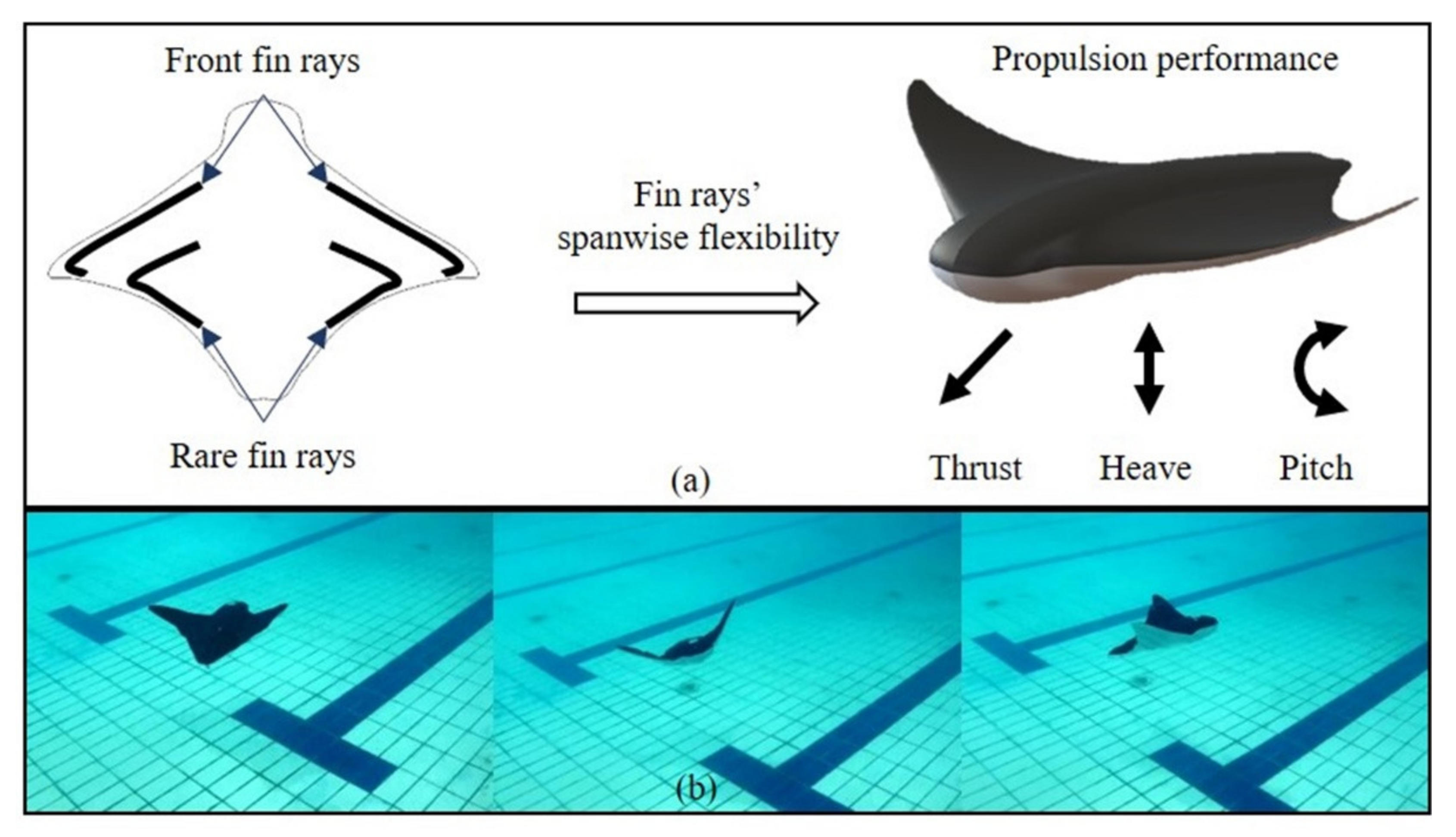
As shown in
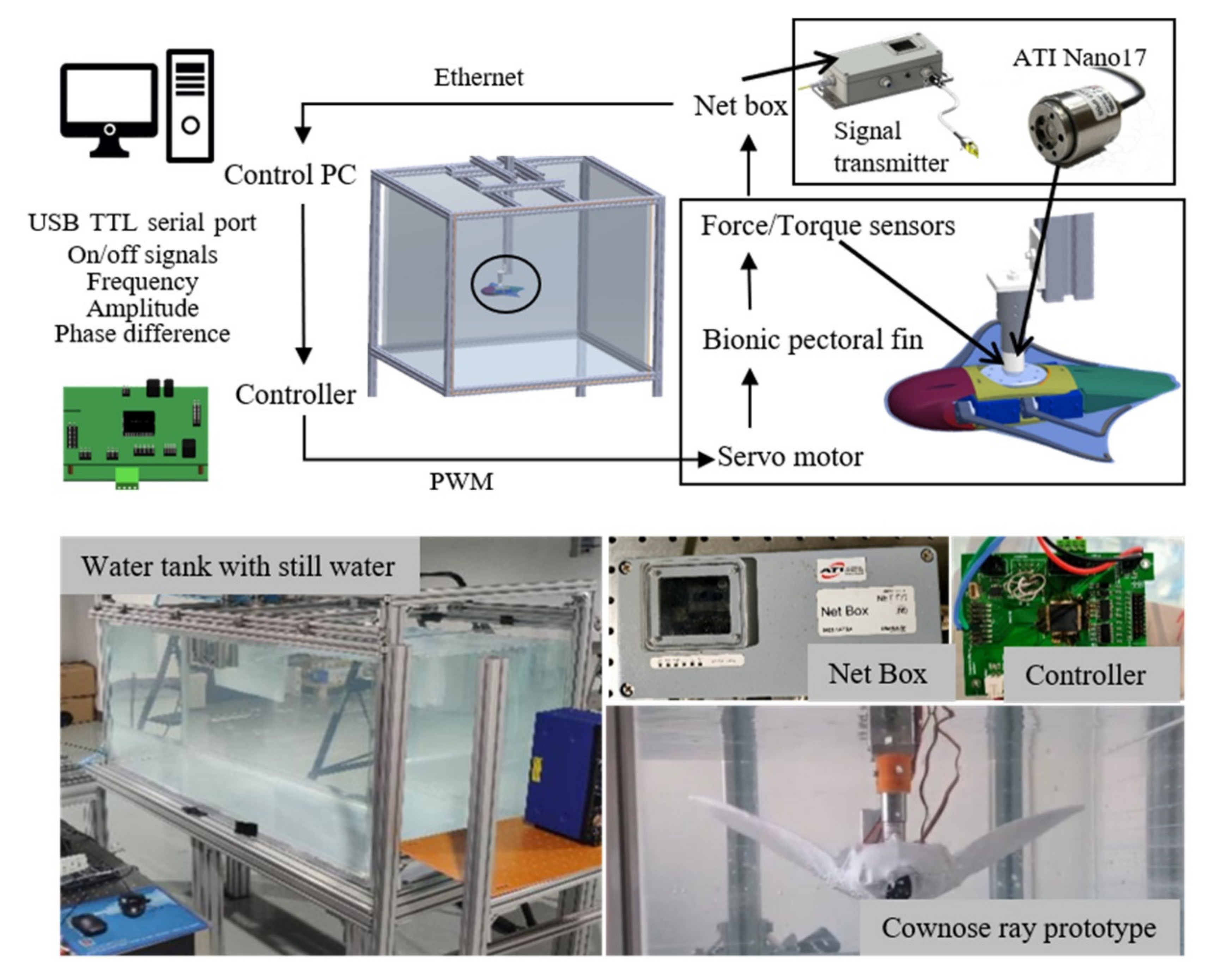
Figure 1a, this paper aims to study the effects of the spanwise flexibility of oscillating pectoral fin on thrust generation and forwarding propulsion stability. Therefore, a bionic pectoral fin with fin rays and fabric skin was designed and set for experimental research on the effects of pectoral fin flexibility on propulsion performance. As shown in
Figure 1b, this fin design was used for the propulsive mechanism of a robotic cownose ray [
26]. The thrust, lift force, and pitching moment of fins with different spanwise flexibility was measured in the water tank. This paper focuses on the design and experimental verification of a bionic pectoral fin.
This paper is organized as follows. In
Section 2, the structure and motion characteristics of the cownose ray are abstracted and modeled. A motor drives a pectoral fin with two fin ray skin, and fabric skin is designed to reproduce the flapping motion of a cownose ray. In
Section 3, the bionic pectoral fin prototype is fabricated and assembled. The mechanical test in a water tank is conductedand the generated lift, thrust, and pitching moment are measured.
Section 4 summarizes the proposed research work and discusses future research prospects.
2. Materials and Methods
2.1. Model of the Bionic Pectoral Fin
According to biological research results, the movement parameters of the cownose ray can be obtained, as shown in
Table 1. [
27,
28] Cownose ray has the oscillatory fin behavior with 0.4 waves per fin length [
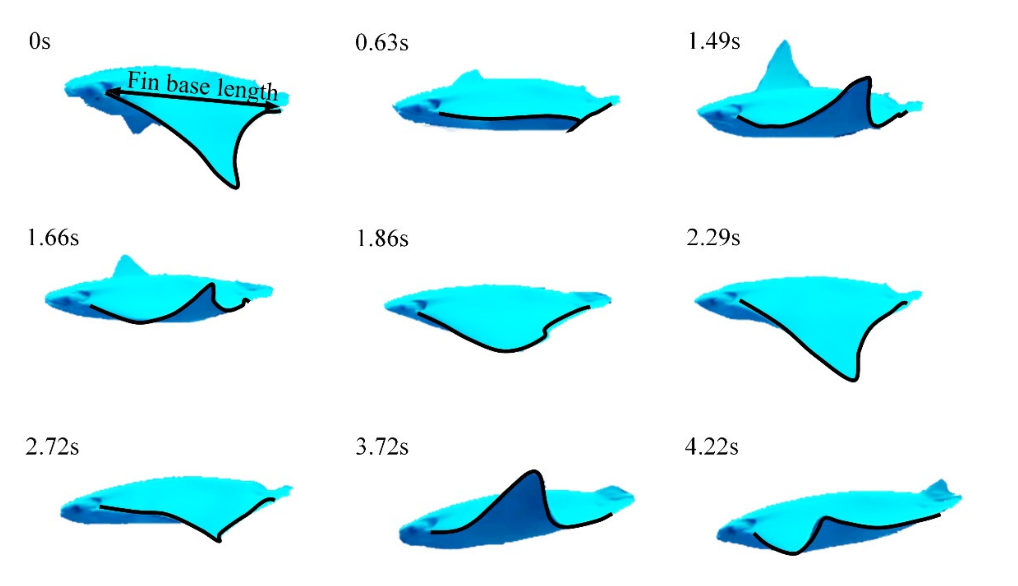
6]. Its complex movement deformation can be divided into two kinds of motions. One is the oscillation along the spanwise direction; the other is the wave transmission motion along the chordwise direction. Based on the swimming video of the cownose ray photographed in the aquarium, shown in
Figure 2, we can clearly see its asymmetrical flapping amplitude and frequency. The asymmetric flapping amplitude corresponds to asymmetric spatial motion, which means that the maximum angle of the pectoral fin flapping up and the maximum angle of the pectoral fin flapping down are not equal. The asymmetric flapping frequency corresponds to asymmetric temporal motion, which means that the time of duration flapping up and the time of duration flapping down are not equal. However, to make it easier to design and control bionic pectoral fins, the feature of spatial-temporal asymmetry is omitted.
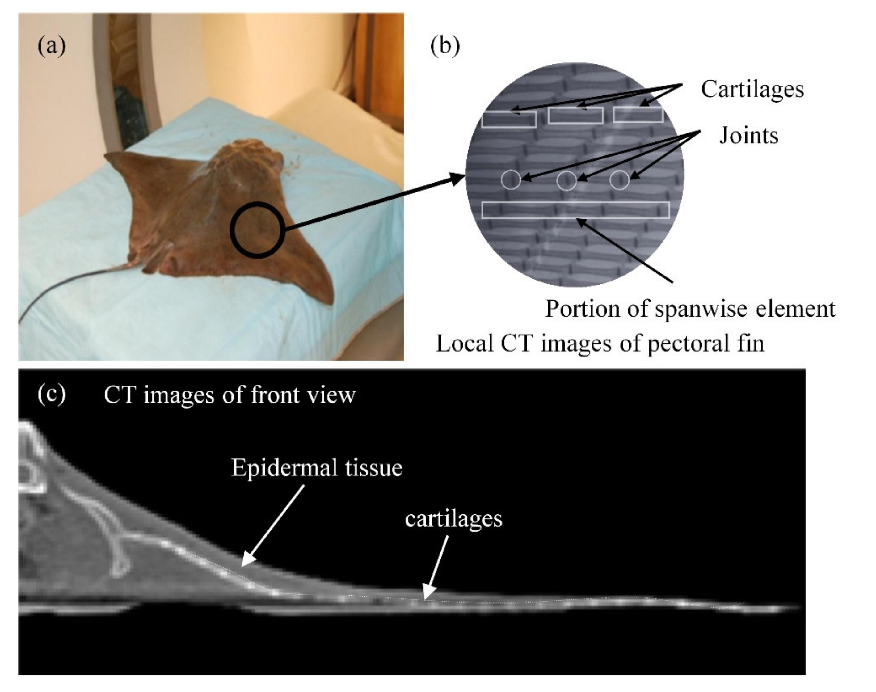
As shown in
Figure 3, the pectoral fin of the cownose ray is composed of cartilages, muscles, tissues, and epidermis [
29]. The muscles drive the movement of cartilages. Meanwhile, the tissues and epidermis are deformed. Therefore, based on the pectoral fin structure of a real cownose ray, the bionic pectoral fin is composed of flapping fin rays (it is equivalent to the cartilages of a cownose ray) and external flexible fabric skin (it is equal to the epidermal tissue of manta ray).
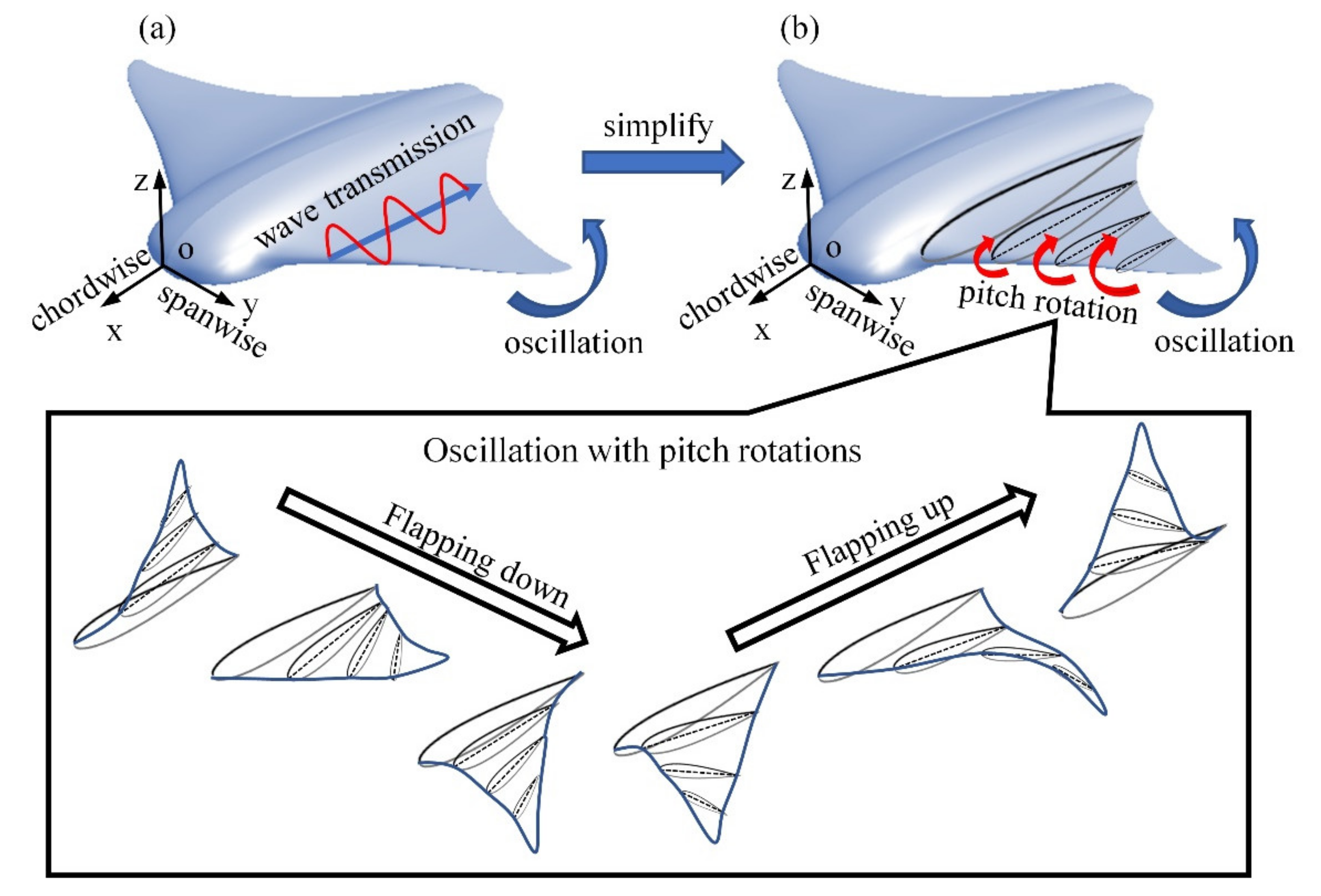
For the bionic pectoral fin design, to mimic the movement of cownose ray better, it is necessary to distribute as many fin rays as possible in the bionic pectoral fin. Still, it will increase the complexity of motion control and machine design. Moreover, the undulate motion of the pectoral fin is not significant. Therefore, as shown in
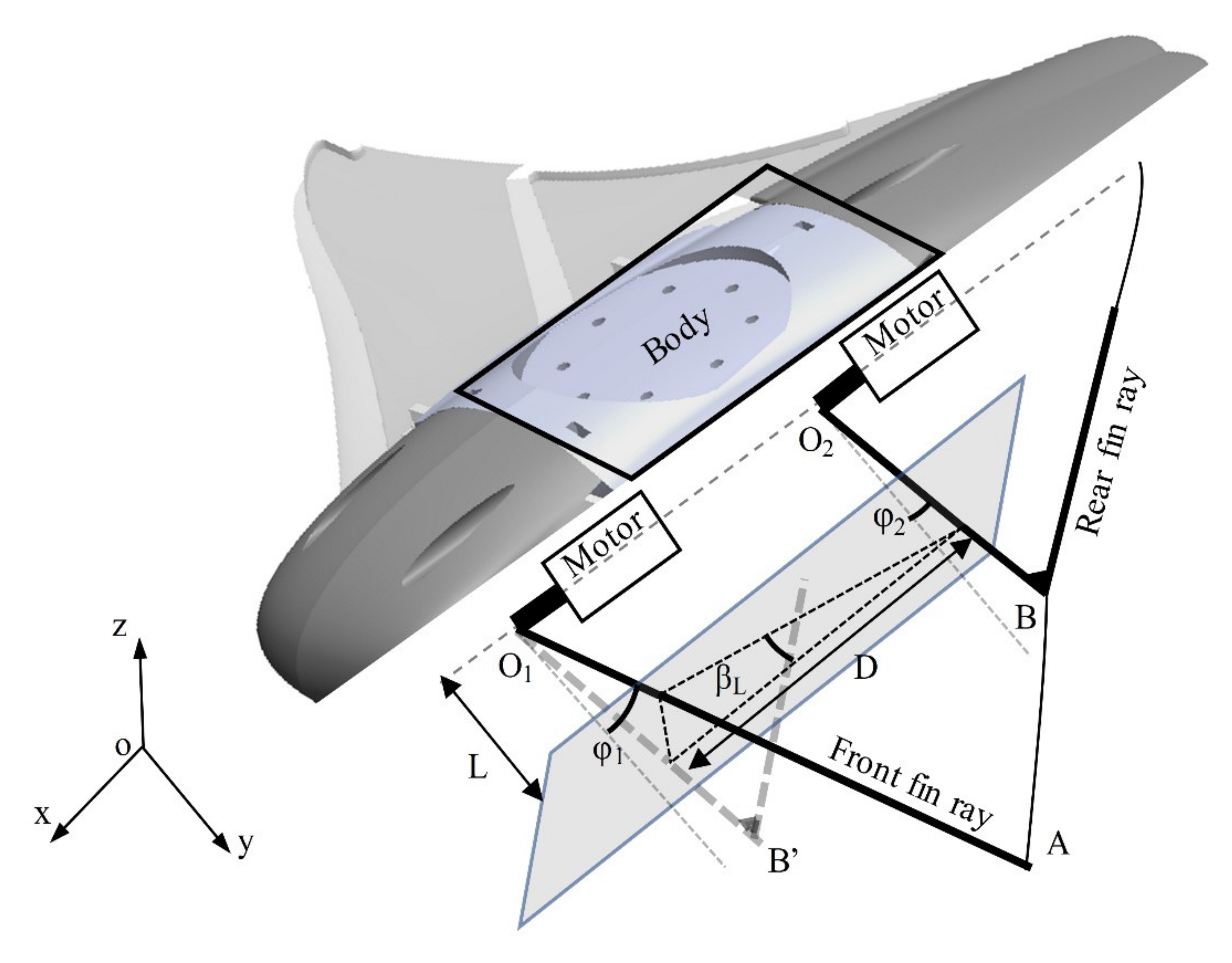
Figure 4, the wave transmission motion along the chordwise direction of the cownose ray can be simplified to a series of pitch rotations parallel to the XOZ-plane and the maximum pitch angle of the pitch rotation is growing along the spanwise direction.
The motor drives the bionic fin rays to realize the controllable movement of the bionic pectoral fin, and the schematic of a parallel-oscillate mechanical is shown in
Figure 5. The following two equations describe the motion control equations of these two fin rays:
where t indicates time, and φ
1(t) and φ
2(t) indicate the deviation angle of the fin rays from the central position at a certain time; φ
max is the maximum flapping amplitude of the fin rays; ω means the angular velocity of fin oscillation, which is equal to 2πf, and f indicates the fin flapping frequency; δ
1 and δ
2 indicate the phase of two fin rays; ξ
1 and ξ
2 are the angles from the central position at the initial time of the fin rays. In this paper, these two angles are set to zero because spatial-temporal asymmetry is omitted.
The motion of the two pectoral fins led to the implicated pitch rotation; the phase difference influences the pitch rotation of the pectoral fin. The pitch angle at a distance of L from the axis of rotation is described by the following equation:
where β
L indicates the pitch angle at a distance of L from the axis of rotation, and D is the distance between two motors, shown in
Figure 5.
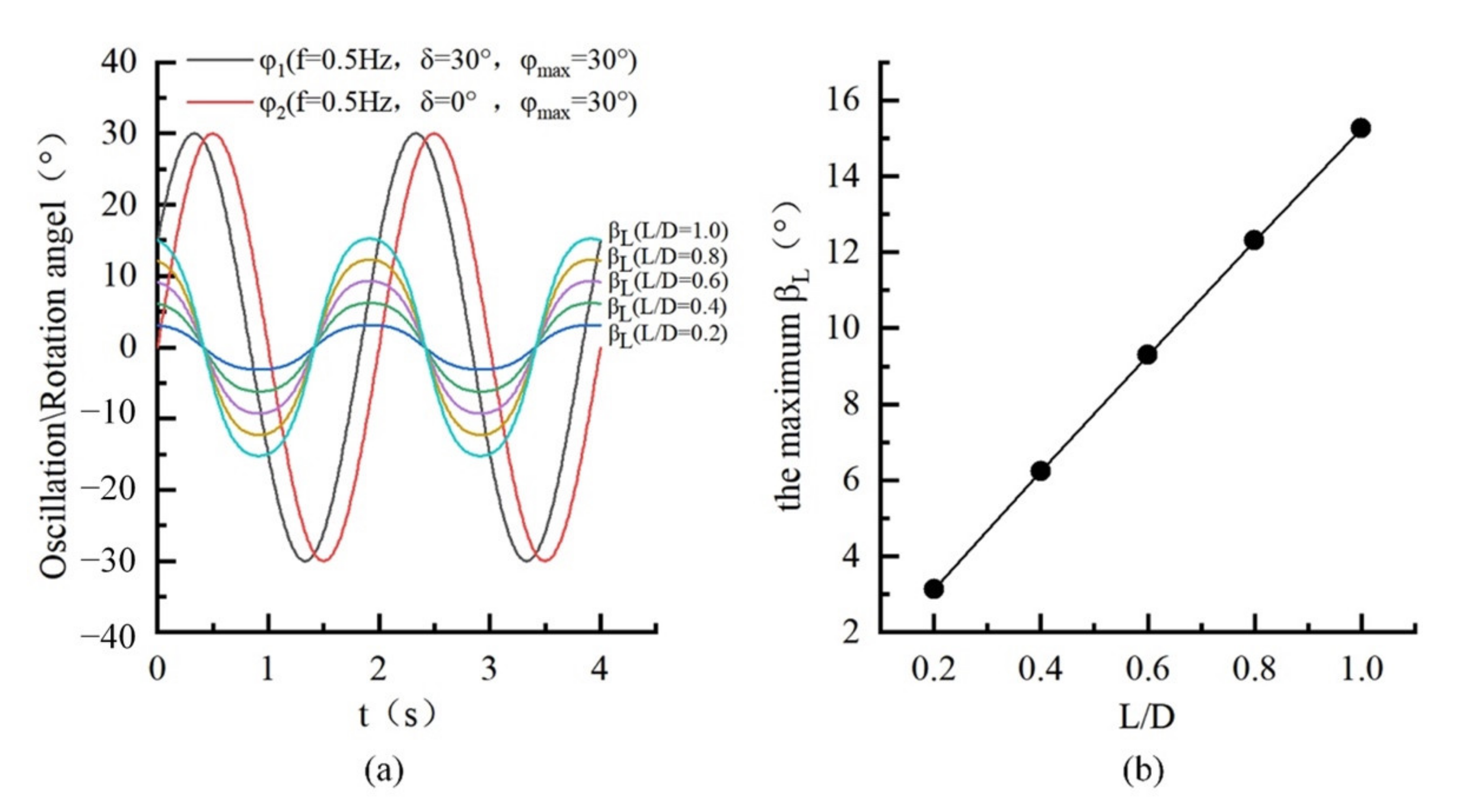
Here, D represents the distance between two motors, as seen in
Figure 5, and the curves plotted in
Figure 6 show the amplitude of pitch angel increased from the root segment to the tip segment of the bionic pectoral fin, which shows that the bionic pectoral fin with two actively controllable flapping fin rays has expected pitch rotation.
2.2. Design of the Experimental Prototype
The experimental prototype is mainly composed of the following parts:
- (1)
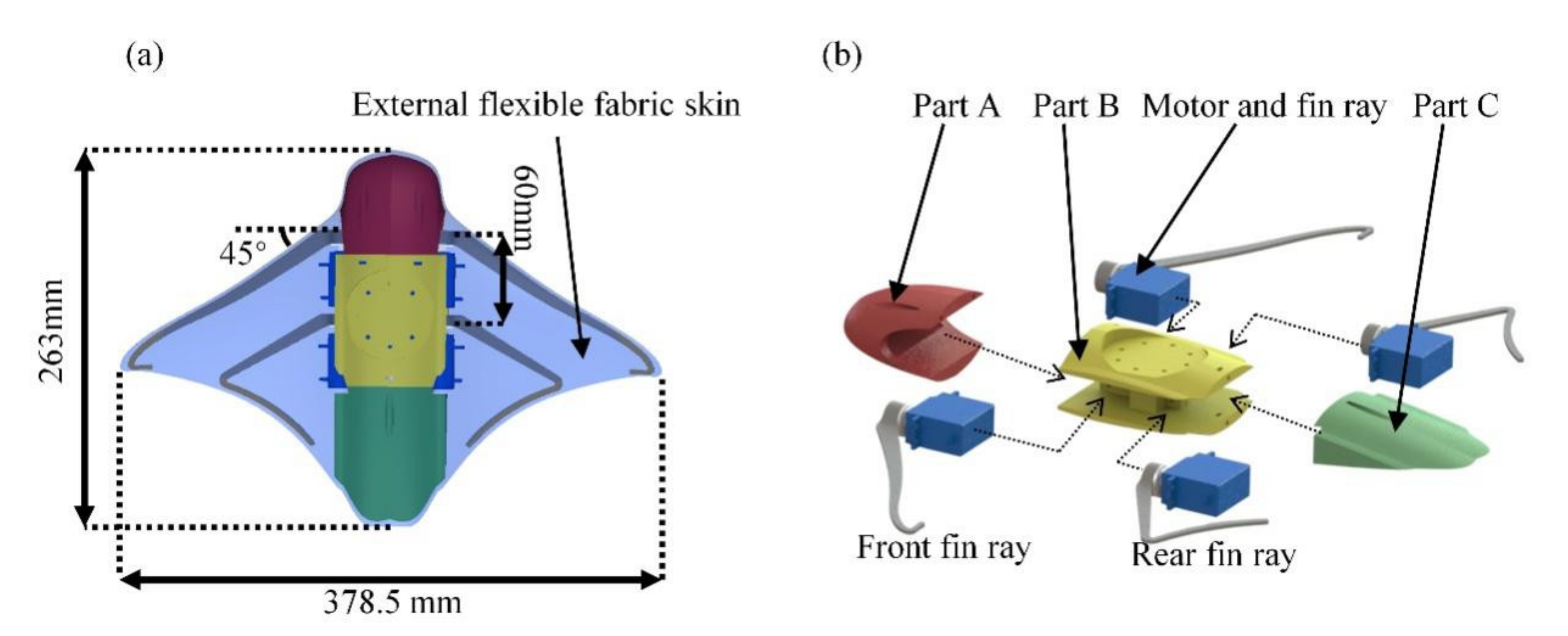
Central body: The central body is designed as shown in the figure, composed of parts A, B, and C, as shown in
Figure 7. All of them were made from polylactic acid (PLA) filament via 3D printing. The shape is mainly based on the top projection contour of the cownose ray. National Advisory Committee for Aeronautics (NACA) airfoils are used as cross-sections. All servo motors and force measuring sensors are assembled in Part B.
- (2)
Pectoral fins: The experimental bionic prototype contains a pair of symmetrical pectoral fins composed of flapping fin rays and external flexible fabric skin. The shape of the experimental prototype is based on a real cownose ray. To retain the shape of the pectoral fin during movement, the front fin ray is relative to the leading edge of the pectoral fin, and the rear fin ray is designed as an open triangle relative to the trailing edge of the pectoral fin. The tip of the fin rays is arc fitted to prevent external flexible fabric skin from damaging. The structure parameters of the pectoral prototype are shown in
Figure 7.
The pectoral fin is driven by the servo motors: The model of servo motors is Xunlongzhe (Xintenghui, Guangdong, China), and the continuous operation torque is 3 Nm. The external flexible fabric skin is made of high elastic spandex, which can avoid the problem that the centroid of the bionic fin changes continuously due to the deformation of the pectoral fin under underwater pressure. The servo motors drive the fin rays, and the fin rays cause the skin to deform. The skin ensures the shape characteristics of the pectoral fin. The flexibility of the pectoral fin is reflected in the stiffness of fin rays.
Compared with the pectoral fin made of silicone rubber, the external flexible fabric skin is more convenient and economical. Moreover, the skin structure reduces the internal friction caused by the relative movement of the skeleton.
- (3)
Power supply and control: Four servo motors were used, all of which are externally supplied power; the STM32F103 (Segbuy, Shaanxi, China) device is used as its core chip. The sinusoidal control strategy is integrated into the controller and applied to the servo motor of front fin rays and rear fin rays.
2.3. Experiment Setup
Thrust is an essential factor affecting the propulsion performance of the bionic cownose ray, which mainly affects the maneuverability of forwarding swimming. In addition, In the MPF propulsion mode, pitch motion and heave motion always occur in forward swimming, which primarily affects forward swimming stability. To study the effects of pectoral fins’ flexibility on forwarding propulsion performance, a series of flexible pectoral fin rays was used and covered with the same elastic skin. The thin fin rays are composed of five different thicknesses: 1.5 mm, 2 mm, 2.5 mm, 3 mm, and 3.5 mm. Experiments are carried out on the five thicknesses of the pectoral fin skeleton under a series of motion control parameters to study the effects of pectoral fins’ flexibility on its propulsion performance.
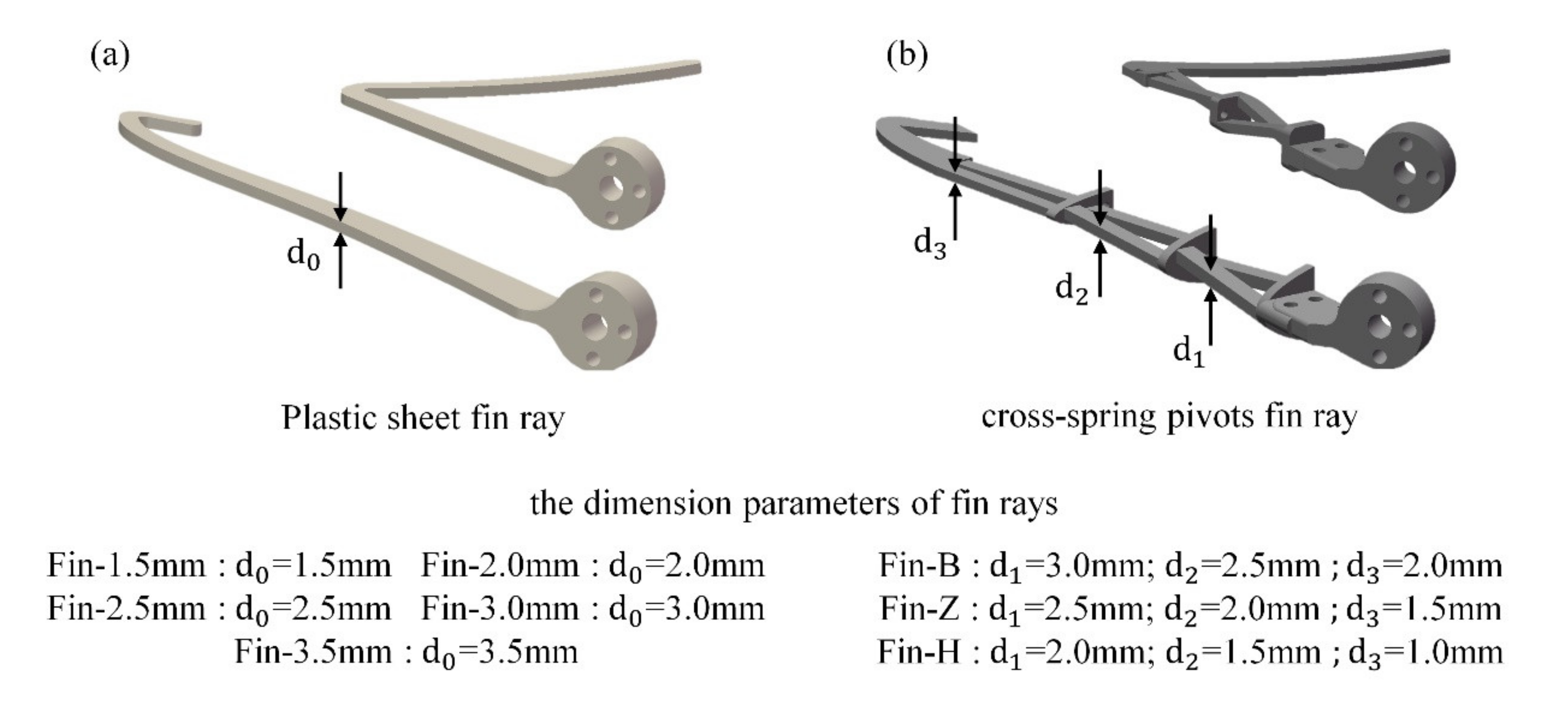
According to the previous anatomical research results on the pectoral fins’ structure [
30], it can be concluded that the pectoral fins of cownose ray have the characteristics of high root stiffness and low tip stiffness. Therefore, the pectoral fin ray with a cross-spring pivots structure is designed to study the effects of the pectoral fin with more obvious stiffness variation on propulsion performance. The cross-spring pivot is a kind of flexure hinge that produces higher stiffness. [
31] The series design of cross-spring pivots is used to make fin rays with more obvious stiffness variation. All fin ray parameters are shown in
Figure 8. For each pectoral fin, the fin rays with the same thickness or the cross-spring pivots with the same structure were used for the front fin ray and the rear fin ray. Thus, the stiffness difference between the front and rear fin can be ignored, and it is enough to analyze the flexibility of the front fin ray only. The fin rays are made from polylactic acid (PLA) filament (with Young’s Modulus of 1.514 GPa) via 3D printing.
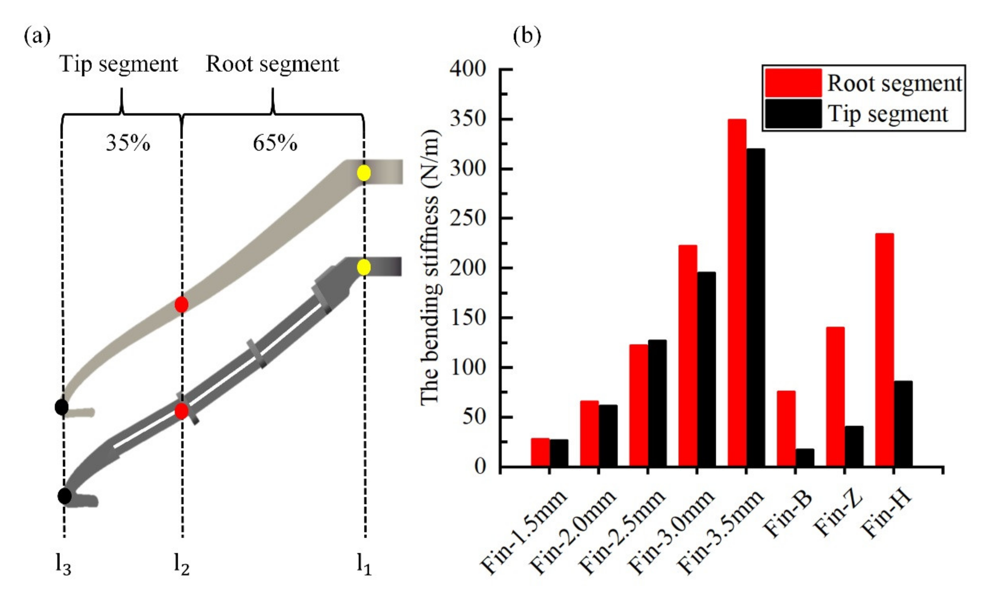
According to the bending rules for animal propulsion [
32], the fin rays are divided into two parts by three lines. Sixty-five percent of fin rays are root segments with higher stiffness, and another 35% are tip segments with lower stiffness. Fin rays’ bending stiffness can quantify the bionic pectoral fins’ flexibility. The bending stiffness is defined as the force exerted at the load points divided by the fin’s deflection at load points. Finite element simulation is used to obtain the stiffness of the root segment (fix the yellow mark point on the fin to obtain the force required for the unit displacement of the red mark point) and tip segment (fix the red mark point on the fin to get the force needed under unit displacement of black mark point). The simulation results are shown in
Figure 9.
As shown in
Figure 10, the force measuring experimental platform mainly includes an experimental water tank, force measuring sensor, experimental prototype, controller, DC power supply, and control PC.
The resolution of Fx, Fy, and Fz is 1/80 N, the torque is 1/16 Nmm, and the acquisition frequency is set to 100 Hz. [
33]
The force-torque sensor was connected to the upper section of the experimental prototype. The shell of the force-torque sensor is connected to the aluminum profile through an adapter. All aluminum profiles are fixedly connected with the experimental water tank.
The size of the experimental pool is 2.0 m (length)× 1.2 m (width)× 1.0 m (height), and water is filled to a depth of 0.8 m during the experiment. The experimental prototype is spaced 0.4 m away from the water’s surface and 0.4 m from the tank’s walls to reduce the surface and the wall effect. A wave suppression plate is placed on the wake side of the experimental water tank to reduce the influence of reflux.
The feedlines of the experimental prototype and the force-torque sensor are placed outside the water tank. The controller is powered by an external DC power supply, the force measuring sensor is connected with the net box, and a 12 V DC power supply independently powers the net box. The controller is connected to the computer through a wireless serial port, and the sensor net box is connected to the computer through a network cable and transmits data.
According to the straight swimming motion law of real cownose ray, the pectoral fin flapping frequency of the test prototype is 0.3–0.7 Hz, the flapping amplitude is 20–40 degrees, and the phase difference between the front and rear fin is 20–40 degrees. The simple comparison method combines the motion parameters into 13 sets of control parameters.
Eight pectoral fin design is tested in 13 sets of control parameters. There are 104 groups of experiments in total. Ten complete oscillation cycles are collected in each set. To reduce the influence of external high-frequency disturbance and equipment signal noise on the measured data, the sensor is set with a low-pass filter with a cut-off frequency of 5 Hz to process the measured data:
In each group of experiments, the data processing method is as follows:
- (1)
For each group of experiments, the thrust values from 10 oscillation cycles are averaged to calculate the average thrust. To compare various fin designs, each fin design has a set of 13 average thrust values and 13 maximum thrust values.
- (2)
The peak of the positive lift values from 10 oscillation cycles is searched for each fin design. The average of 10 peak values is taken as the maximum lift force. The maximum lift force can be an essential parameter to measure heave motion stability.
- (3)
The maximum pitch moment is obtained in 10 oscillation cycles to measure pitch motion stability.
3. Results
A series of experiments was carried out in the water tank to test the effects of fin stiffness on propulsion, lift, and pitch torque under different controllable parameters. As described in
Section 2, a set of controllable parameters includes the flapping amplitude of the pectoral fin, the flapping frequency, and the phase difference between the front and rear fins of the bionic pectoral fin.
3.1. Thrust Performance
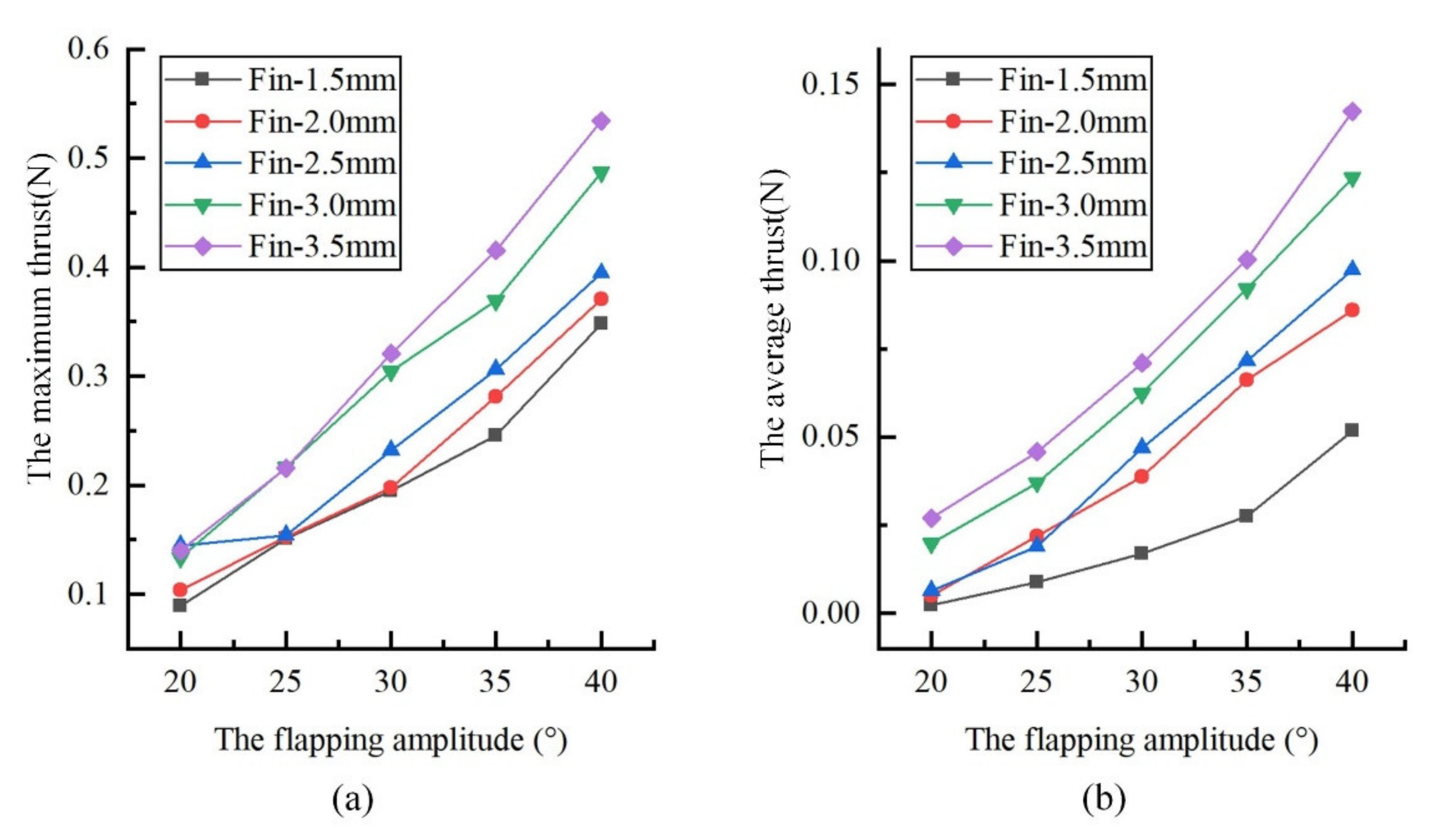
When changing the flapping amplitude, the influence of fin flexibility on thrust is shown in
Figure 11. The amplitude is controlled between 20° and 40°; the selected amplitude angle is 20°, 25°, 30°, 35°, and 40°; the selection of fin amplitude theoretically represents the flapping amplitude of the bionic pectoral fin. When starting the experiment, select the flapping frequency as 0.5 Hz and the flapping phase difference as 30°. The average thrust increases with the amplitude becoming larger; the maximum thrust conforms to similar rules. With the increase in the thickness of the pectoral fin, the average thrust and the maximum thrust displayed an upward trend, and the influence of stiffness on thrust is more significant under the control parameters with large amplitude.
Ati-nano17 (six-axis force sensor) is used to measure thrust, lift force, and pitching moment. The calibration type is si-50-0.5. The sensing range of Fx (thrust) and Fy (transverse force) is 50 N, Fz (lift force) is 70 N, and the torque in all directions is 500 Nmm.
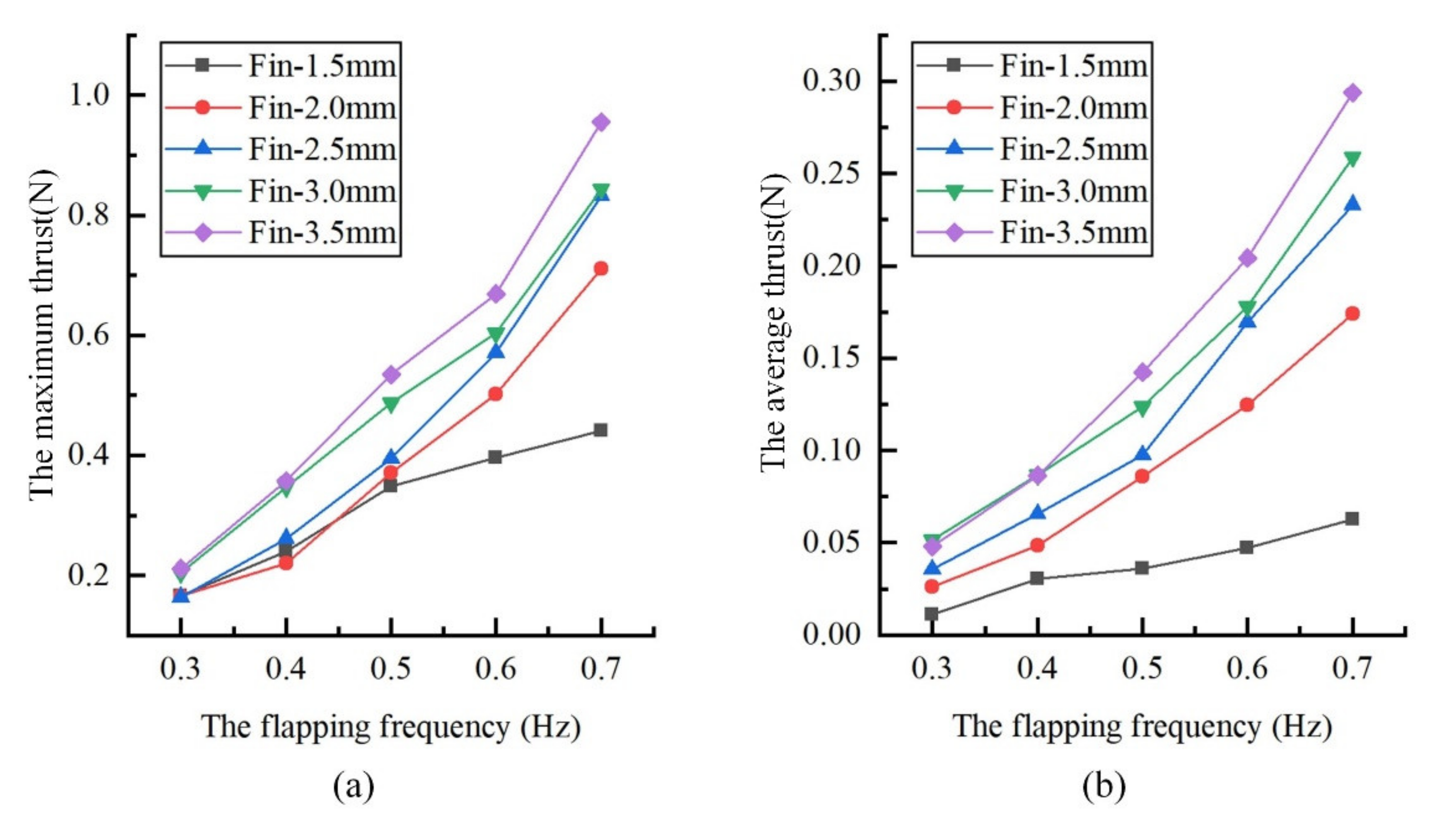
Figure 12 shows the influence of fin stiffness on propulsion when changing the flapping frequency. The control frequency of the fin line ranges from 0.3 Hz to 0.7 Hz. Five groups of frequency control parameters, 0.2 Hz, 0.3 Hz, 0.4 Hz, 0.5 Hz, 0.6 Hz, and 0.7 Hz, are adopted. At the same time, select the amplitude of 40° (the amplitude value corresponding to the maximum thrust in the above experiment) and the phase difference of 30°. In the test range of flapping frequency, the average thrust and peak value increases significantly with frequency increase. With the increase in the thickness of the pectoral fin, the increase in fin stiffness, the average thrust, and peak thrust show an upward trend, and the influence of stiffness on thrust is more significant under the control parameters of high frequencies.
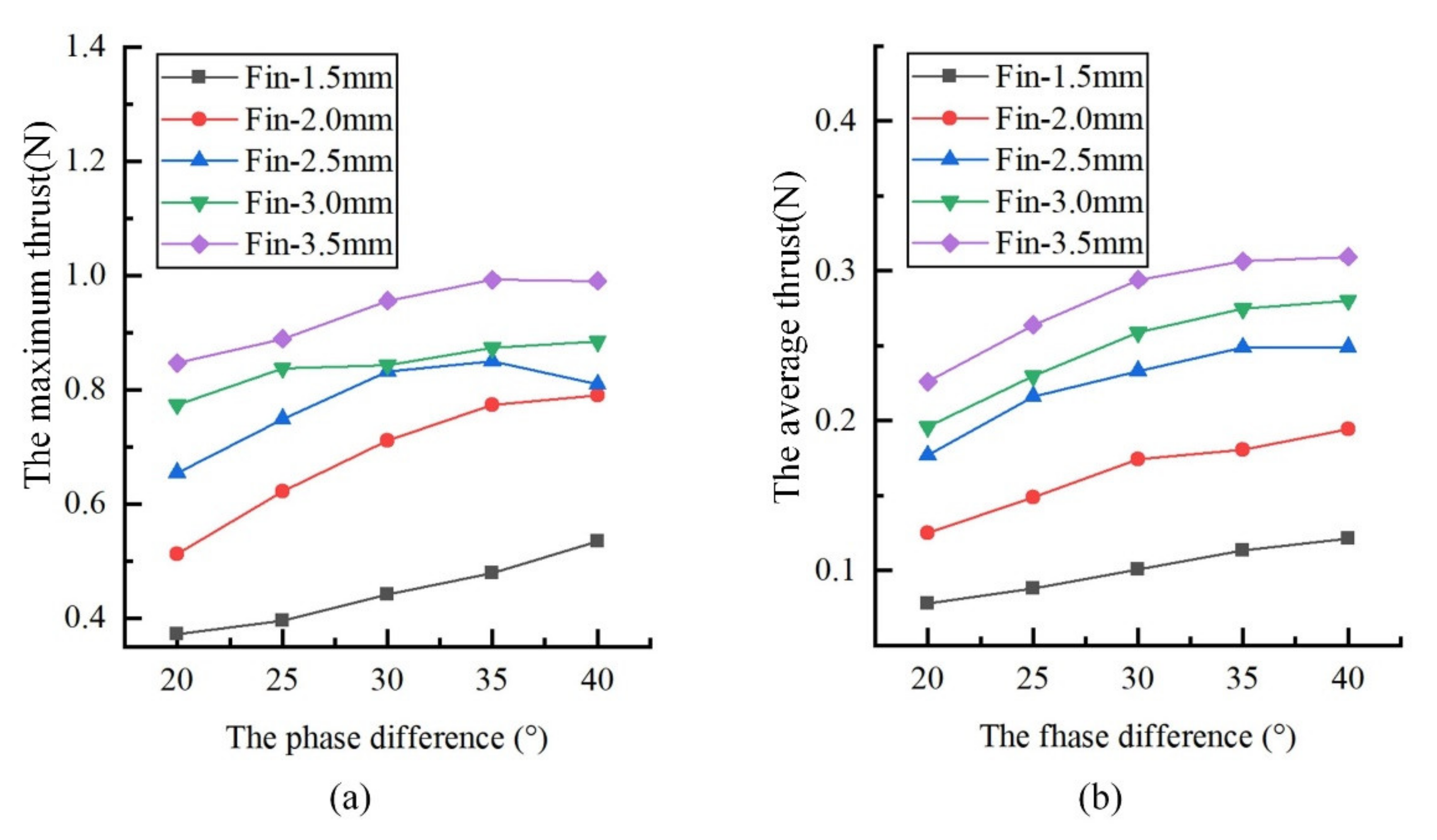
When changing the phase difference of the flapping wing, the influence of fin stiffness on propulsion is shown in
Figure 13. The phase difference is controlled from 20° To 40°. The selected phase difference is 20°, 25°, 30°, 35°, and 40°. At the same time, the flapping amplitude is 40° (the amplitude value corresponding to the maximum thrust in the above experiment), and the flapping frequency is 0.7 Hz (the frequency value corresponding to the maximum thrust in the above experiment). In the test range, the average thrust and peak thrust increase slightly and then tend to be flat with the increase in flapping phase difference. With the increase in pectoral fin thickness, average thrust and peak thrust increased.
The trend of propulsive force shows that the propulsive ability of bionic robotic fish can be improved by simply increasing the flapping amplitude, frequency, and phase difference within this flapping amplitude range. At the same time, it also shows that fin stiffness is also an essential factor affecting propulsive force. Increasing stiffness is conducive for generating propulsive force, and the effect is more significant when flapping amplitude and frequency are higher.
3.2. Lift Force and Pitching Moment Performance
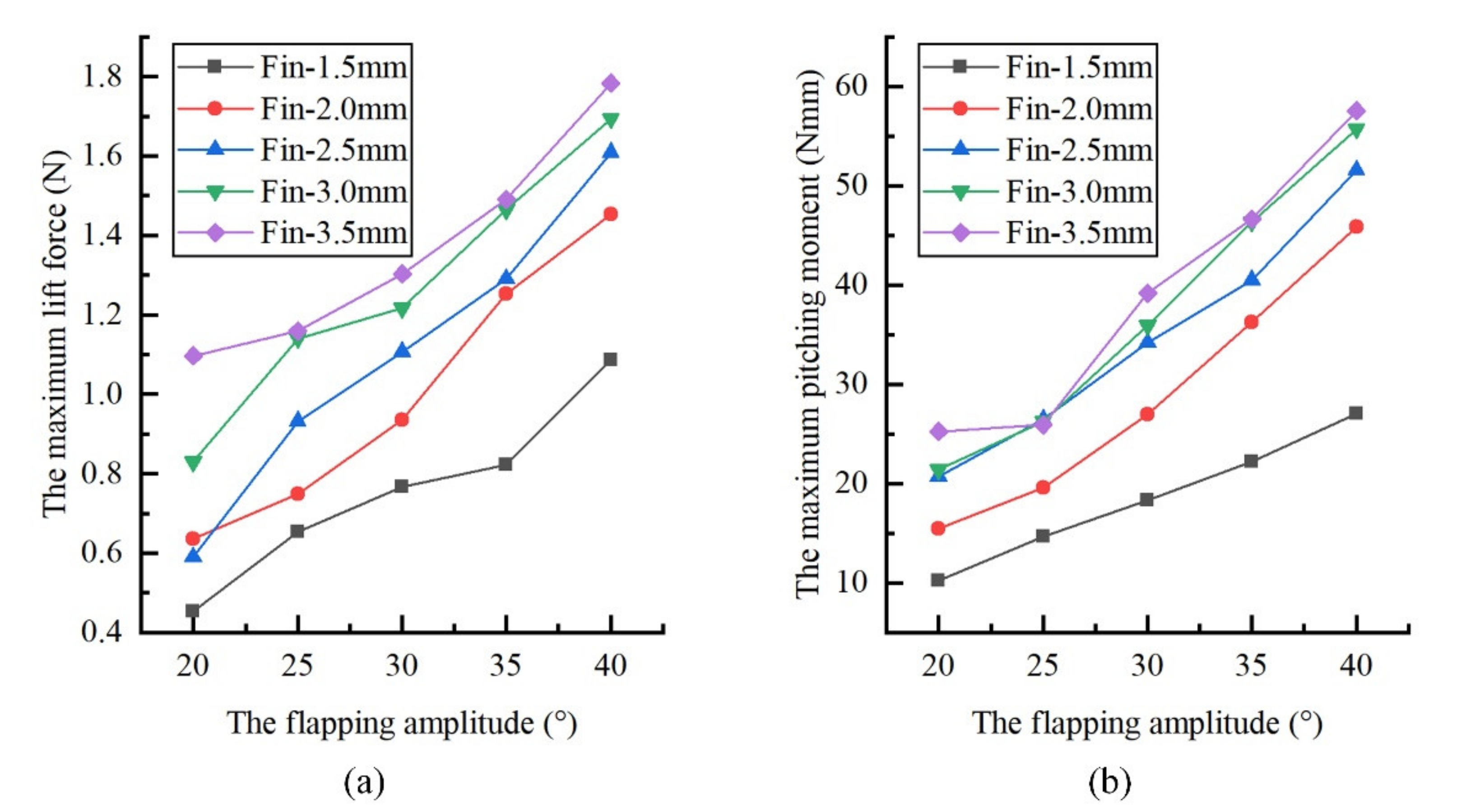
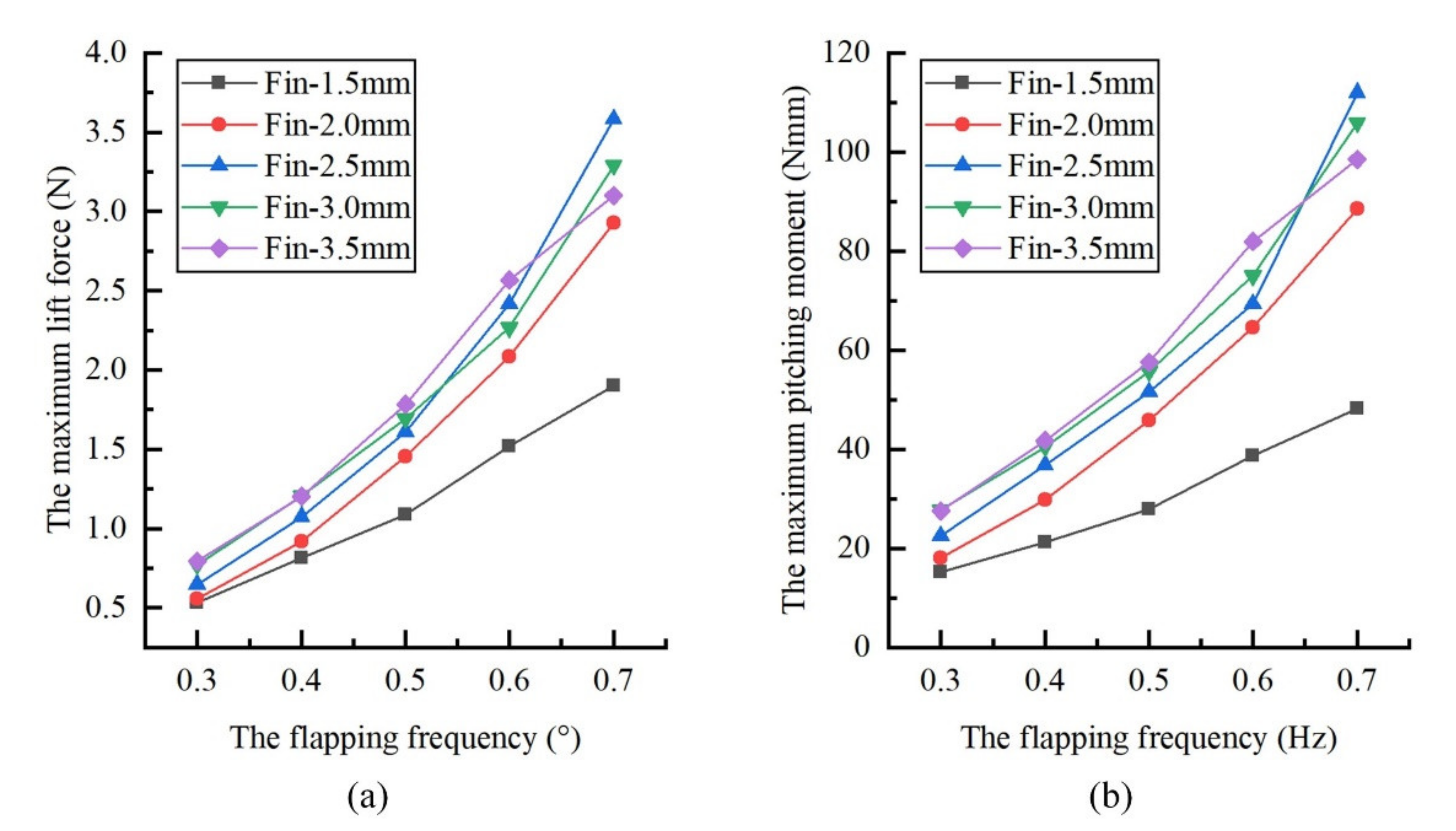
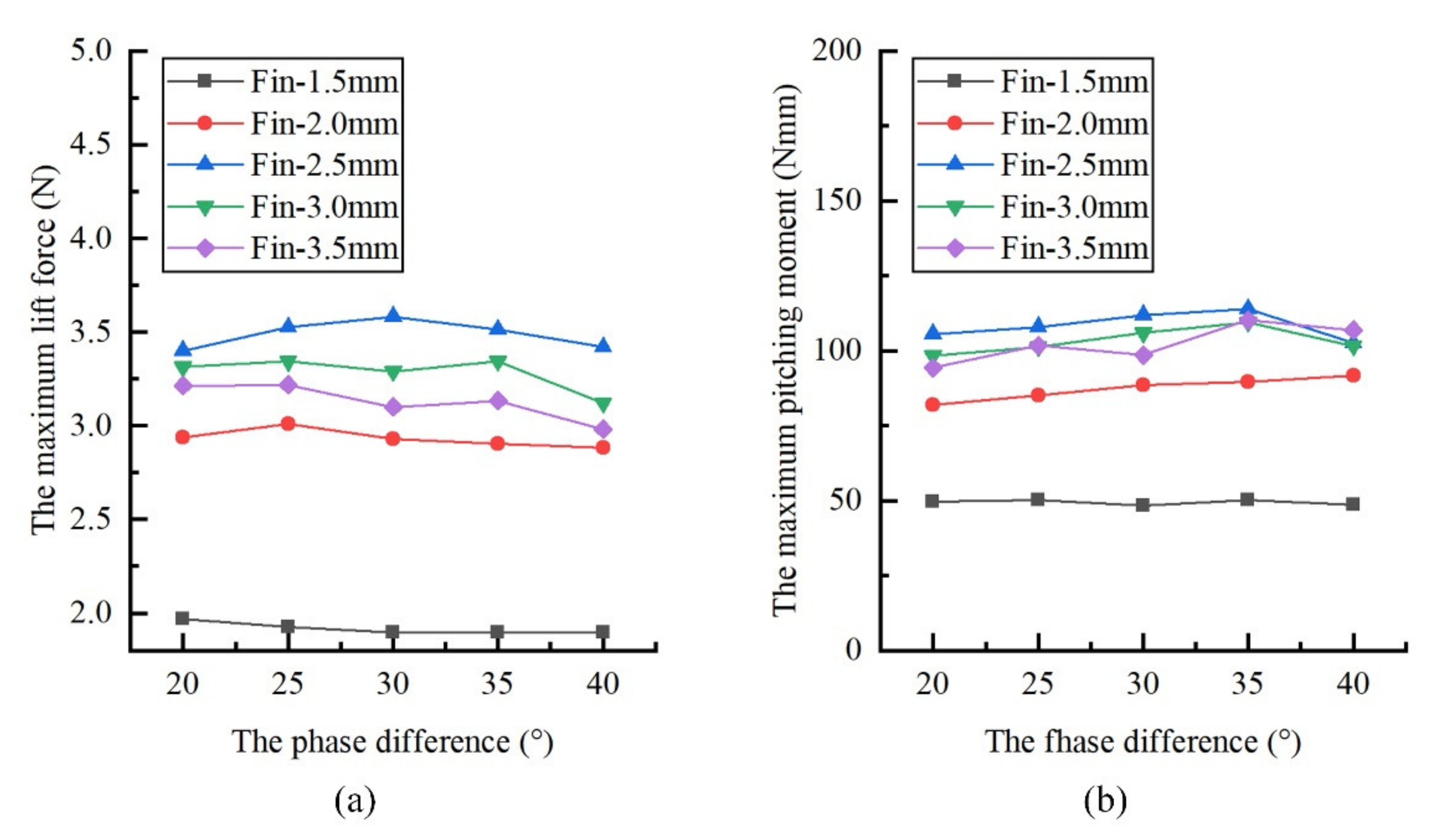
Under the same control parameters, the bionic prototype’s peak lift and pitch torque increase with the flapping amplitude and flapping frequency, but the change of phase difference has no obvious effect on the peak lift and pitch torque. The experimental result shows in
Figure 14,
Figure 15 and
Figure 16. In addition, when the frequency is less than or equal to 0.5 Hz, the lift and pitch moment of the bionic prototype increase with the increase in the thickness of the pectoral fin. When the frequency is 0.7 Hz, the pectoral fin with 2.5 mm fin rays can produce a higher lift and pitch moment. It shows a coupling relationship between the fin thickness and flapping frequency. Moreover, the fin rays with large stiffness have high thrust and less lift at high frequency. It is a scheme that considers straight travel acceleration mobility and heaves stability. As the skeleton thickness of the thin plate pectoral fin exceeds 2.0 mm, the influence of pectoral fin stiffness on the pitching moment gradually slows down.
3.3. Effects of Bionic Pectoral Fins’ Flexibility on Forwarding Propulsion Performance
The cross-spring pivot fin rays with stronger stiffness variation are also tested with the same motion parameters; the results show that the propulsive ability of bionic cownose ray shows a similar trend under different fin ray designs, and it can be seen in the
Supplementary Materials.
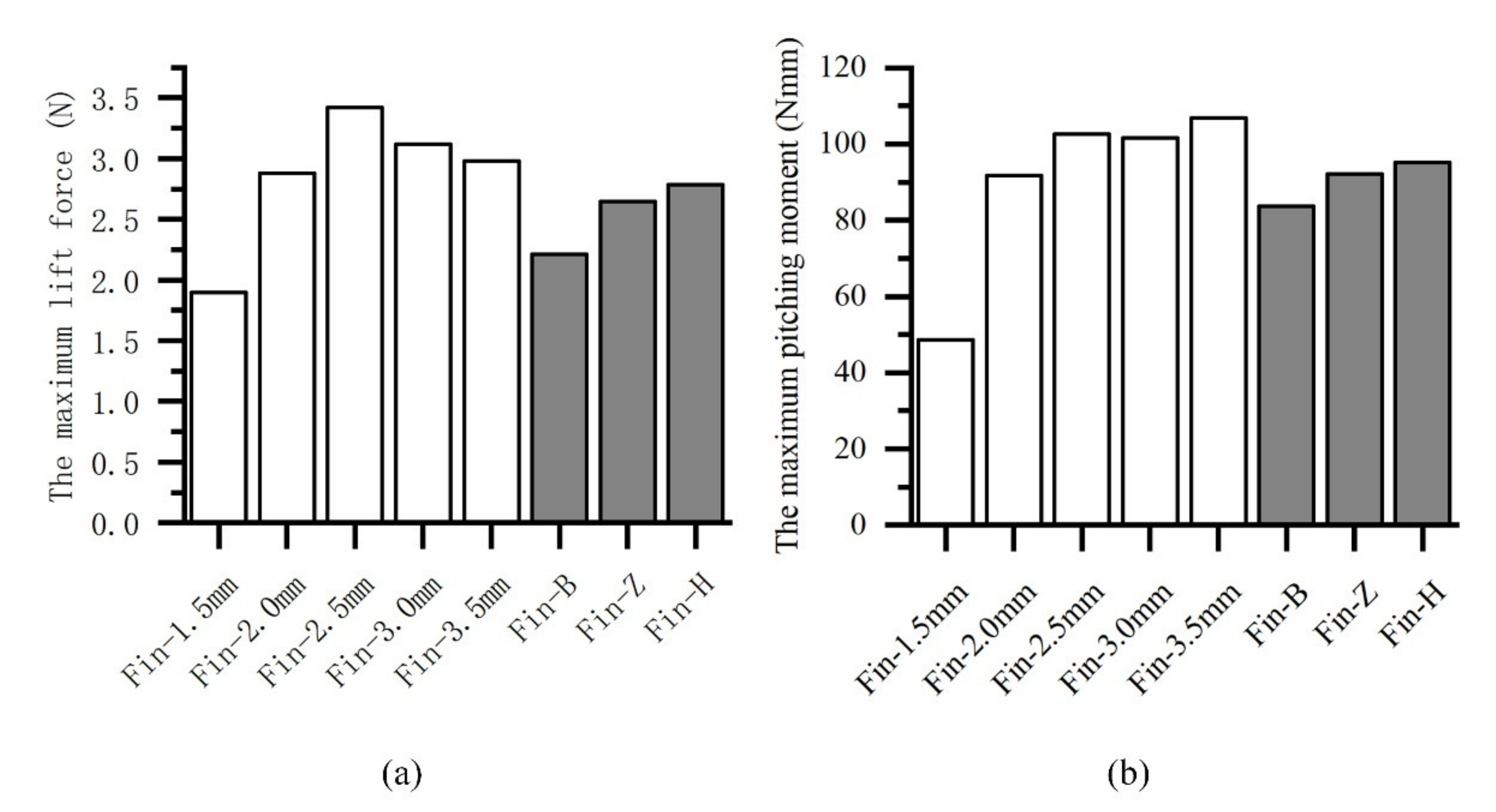
According to the previous anatomical research results on the structure of pectoral fins, it can be concluded that the pectoral fin of a cownose ray has the characteristics of large root rigidity and large tip flexibility. Therefore, the cross-spring pivot fin rays design is adopted to explore the influence of natural biological structures on propulsion performance. This paper aims to reduce the lift and pitching moment as much as possible while maintaining a high thrust to increase the heave stability and pitch stability when the bionic cownose ray is swimming straight. Based on the previous experiment results, the experimental group with the maximum thrust of all experiment results is selected to compare the thrust, lift and pitch moment under different fin designs. The corresponding control parameters are as follows: the frequency is 0.7 Hz, the amplitude is 40 degrees, and the phase difference is 40 degrees.
The experimental results are shown in
Figure 17 and
Figure 18; the cross-spring pivot fin ray designs with high stiffness root segment and low stiffness tip segment can maintain high thrust and slightly decrease lift and pitching moment.
White columns: The experimental results of the fin rays made by plastic sheets of five thicknesses. Gray columns: The experimental results of the fin rays made by three fin rays with more obvious stiffness variations.
4. Discussion
According to the characteristics of the pectoral fin of a cownose ray, this paper observes, models, and uses the motion characteristics of the pectoral fin of the cownose ray to guide the design of driving the pectoral fin and the control strategy applied to the bionic pectoral fin prototype. The structural features of the pectoral fin of the cownose ray are extracted from biological literature, including body shape, cross-section, and cartilage. A pectoral fin structure composed of two fin rays and fabric skin is designed, driven by the motor to produce flapping and pitching motions. To explore the influence of pectoral fins’ spanwise flexibility on its propulsion performance, pectoral fin rays with different stiffness are adopted; through the force measurement experiment in the water tank, the impact of pectoral fin stiffness on the propulsion performance of the bionic prototype is explored under various controllable motion parameters. The results show that the propulsion performance of the bionic pectoral fin has a strong correlation with the flexibility of the pectoral fin. Through the experiment of the pectoral fin rays with cross-spring pivot, the results show that the high stiffness root segment combined with low stiffness tip segment pectoral fin ray design can not only maintain a large thrust but also slightly decrease heave and pitch, and it provides a very important guiding significance for the design of bionic prototypes with pectoral fins.
In future works, the study will concentrate on the parametric modeling of the pectoral fin’s flexibility and quantify the effects on propulsion performance. Meanwhile, effort will be invested into studying the autonomous swimming of bionic cownose rays and improving the swimming performance through the flexible design of the pectoral fin. The developed bionic cownose ray can be used in resource detection and underwater exploration in an unknown complex environment in the future.


 ,
, 


