Article

Bioinspired Central Pattern Generator and T-S Fuzzy Neural Network-Based Control of a Robotic Manta for Depth and Heading Tracking

1
School of Marine Science and Technology, Northwestern Polytechnical University, Xi’an 710072, China
2
Unmanned Vehicle Innovation Center, Ningbo Institute of NPU, Ningbo 315103, China
3
Key Laboratory of Unmanned Underwater Vehicle Technology of Ministry of Industry and Information Technology, Xi’an 710072, China
*
Author to whom correspondence should be addressed.
J. Mar. Sci. Eng. 2022, 10(6), 758; https://doi.org/10.3390/jmse10060758
Submission received: 30 April 2022 / Revised: 26 May 2022 / Accepted: 28 May 2022 / Published: 30 May 2022
(This article belongs to the Special Issue Frontiers in Deep-Sea Equipment and Technology)

Abstract

:
Aiming at the difficult problem of motion control of robotic manta with pectoral fin flexible deformation, this paper proposes a control scheme that combines the bioinspired Central Pattern Generator (CPG) and T-S Fuzzy neural network (NN)-based control. An improved CPG drive network is presented for the multi-stage fin structure of the robotic manta. Considering the unknown dynamics and the external environmental disturbances, a sensor-based classic T-S Fuzzy NN controller is designed for heading and depth control. Finally, a pool test demonstrates the effectiveness and robustness of the proposed controller: the robotic manta can track the depth and heading with an error of ±6 cm and ±6°, satisfying accuracy requirements.

1. Introduction

Over previous decades, with the expansion of the application range of vehicles, the requirements for the mobility and maneuverability of vehicles are getting higher and higher. Although there has been a great development in traditional underwater vehicles [1,2], most of them are rotary body structures with axial thrusters. The theoretical research and applications of such underwater vehicles have been mature, but they have some limitations [3,4], such as low stealth and low maneuverability. Thus, the bionic vehicle has become a popular research trend, and its excellent motion capability makes it suitable for more application situations [5,6]. The manta ray is an example of a bionic vehicle to imitate using the MPF propulsion method. With this method, a manta ray can achieve a variety of motion modes such as forward, turning, and a horizontal roll by pectoral fin alone. Compared with the Body and/or Caudal Fin (BCF) propulsion method, the Median and/or Paired Fin (MPF) propulsion method makes the vehicles more stable when swimming and can be used as a more flexible and stable platform for carrying equipment [7].
Bionic vehicles require the drive of the bionic propulsion mechanisms for their motion. The main methods for driving bionic propulsion mechanisms are kinematic model-based methods, kinetic model-based methods, and Central Pattern Generators (CPG)-based methods [8]. The CPG model-based approach [9,10,11,12,13,14,15] is increasingly used for the actuation of bionic underwater vehicles because it is stable, reliable, and does not require cadence signal feedback, which has a better biological significance. The model’s numerous parameters allow it to simulate complex rhythmic signals, leading to complex gait outputs, and it is well suited for distributed control and multi-drive control and is highly adaptable to the environment. Wang et al. [16] built a CPG network for a multiarticulate machine fish to achieve multimodal 3D motion and demonstrated computationally that the CPG network has better stability than the conventional sinusoidal drive method in maintaining rhythmic motion. Wu [17] used a modified Hopf-based CPG model that allows free adjustment of the phase relationship between outputs to generate rhythmic signals for multimodal swimming and successfully drove a robotic fish to perform various motor actions such as forward swimming, backward swimming, turning, diving, surfacing, etc. Cao et al. [18] improved the CPG model based on a phase oscillator by introducing spatially asymmetric equations with temporally asymmetric equations to complete the driving of a multi-fin strip pectoral fin structure. Wang et al. [19] used the CPG model to control the swimming pattern of a robotic dolphin, which effectively ensured a smooth transition of the motion when the control signal produced a change. By driving the propulsion mechanism, the bionic underwater vehicle can produce a variety of motion states, such as forward swimming, turning, etc. Although the above literature mostly uses CPG drivers, they are mainly focused on achieving the generation of coordinated motion signals. In practical applications, precise control of their motion states is usually required, and the addition of the controller is necessary. Furthermore, there is still a lot of work to do to design a robust controller [19,20] for attitude control of a robotic manta to deal with external disturbances.
Depth and heading tracking, as one of the basic functions of bionic underwater vehicles, are essential parts of the study of bionic underwater vehicle control. Morgansen et al. [21] used a Proportion-Integration-Differentiation (PID) control method to achieve navigation control by tail fin swing deviation while the pectoral and caudal fins were linked to change the pitch angle to achieve depth control. Considering the nonlinear model in depth control and the volume change of the rubber skin caused by water pressure, Shen et al. [22] designed a fuzzy PID controller to achieve depth control by adjusting the internal slider of the bionic dolphin robot. Yu et al. [23] designed a hybrid depth controller combining a sliding mode control and fuzzy control and verified the effectiveness of the controller through constant depth and depth switching experiments. Wei et al. [24] proposed a method based on an active disturbance suppression controller and fuzzy control strategy, which enabled a bionic squid to complete the fixed depth and fast ascent or dive by modifying the wave fin parameters on both sides. Yuan et al. [25] proposed a Back Propagation (BP) neural network controller based on a sliding mode observer to control the yaw angle of a dolphin-like robot fish, but only simulation results were given. However, the above literature is not based on CPG performing the closed-loop control for robotic manta possessing the flexible pectoral fin propulsion mode. In addition, accurate mathematical models of robotic manta are difficult to obtain, which poses a challenge to control. Gong et al. [26] proposed a CPG-based fuzzy control method based on the practical need for research on the control of the rolling motion of a pectoral fin swing propelled robotic fish. Cao Y. et al. [18] proposed a fuzzy controller based on an improved CPG model to accomplish the depth and heading control of a manta ray mimic vehicle. Yet, the method of Gong and Cao relies on expert experience, and the research of taking the uncertainties of the model dynamic into account has not been started.
Hence, on the basis of the foregoing discussions, the main contributions of this work are summarized to introduce a control strategy for robotic manta compared with previous works: A classic T-S fuzzy neural network (NN) controller integrated with an improved CPG-driven network is designed to deal with the model unknown dynamics and the external environmental disturbances. The dynamic control performance is validated by comprehensive pool tests.
The following sections of this paper are described below. Section 2 describes the design of the robotic manta. The improved CPG model and T-S fuzzy neural network-based controller are given in Section 3, and Section 4 presents two sets of experiments, one for depth control and the other for heading control. Section 5 discusses the results and the outlook for future work.

2. The Design of the Robotic Manta

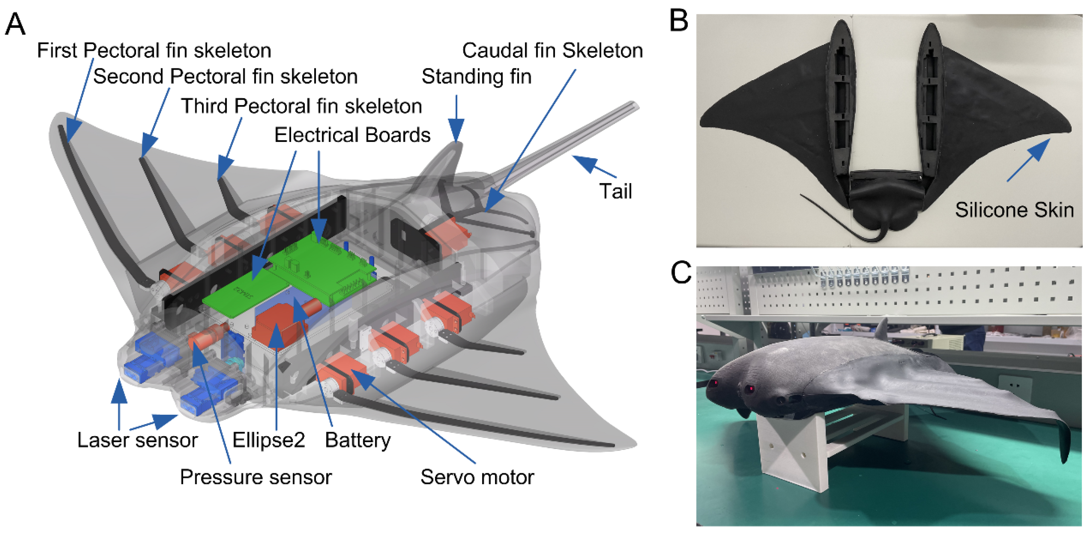
2.1. Overview of Mechanical Structure and Electronic Design

According to the shape characteristics of the real manta ray, the scaled-down model of the real manta ray is modified. Keeping the main body curve, pectoral fin curve, and caudal fin of the scaled-down model, the shape structure of the robotic manta is designed.
The prototype can be divided into four parts: the main body, pectoral fin, caudal fin, and skin. The main body is 3D printed by nylon laser sintering, which has the advantages of small mass and low cost. The pectoral and caudal fins are mainly composed of servo motors and skeletons. The pectoral fin of the prototype adopts a distributed multi-stage skeleton structure, and each skeleton is driven by a servo motor. The caudal fin consists of a caudal fin skeleton with a servo motor. The skeletons are cut from carbon fiber sheets of different thicknesses. The skin is made of soft silicone casting, which is installed on the skeletons to form a complete pectoral fin surface and a three-dimensional caudal fin form, replacing the muscles and skin of real creatures. The structure specifications of the robotic manta are presented in Figure 1.
The hardware of the control system adopts a modular design to enhance the portability of the hardware system. When a module fails, it is easy to repair. As illustrated in Figure 2, the control system hardware structure of the robotic manta is composed of five parts: a microcontroller, actuator module, sensor module, power module, and Radio Frequency (Radio Frequency) wireless module. The microcontroller receives information from the sensor module and RF module, runs control algorithms, generates a CPG signal, and computes the control value. The sensor module measures the depth and attitude information. The actuator module consists of seven servos and achieves the motion control of a robotic manta. The main role of the RF wireless module is to transmit the parameters and commands from the remote host system. All the modules are integrated into the electronic compartment of the main body of the vehicle. The PC is also an important module for human-computer interaction which can modify parameters, delegate commands, and receive the status data returned from the robotic manta. The technical specifications of the robotic manta are presented in Table 1.

2.2. Basic Forms for the Movement of the Pectoral and Caudal Fins

The main source of power for a conventional vehicle is a propeller structure or a heavy buoyancy system, but the robotic manta does not have either of these mechanisms. Its main power source is the pectoral fin structure. There is a complex wave transmission during the pectoral fin flutter, but it can be briefly decomposed into a propulsion wave along the chordal direction and a propulsion wave along the spreading direction. The fluctuations in the spreading direction are reflected in the sine wave-like trajectory of end points of pectoral fin skeletons. The fluctuation in the chordal direction is reflected as the phase difference between the sine wave-like trajectories of end points of pectoral fin skeletons. As shown in Figure 3, different skeletons are driven by a servo which can realize the fluctuation transmission in both directions.
The position of each servo is fixed, and the servos are connected to the skeletons through adapters, respectively. The mechanism of the left pectoral fin and the right pectoral fin are in the same principle and are in a mirror image relationship. Taking the left pectoral fin during an upstroke motion as an example, at the time t = 0 , the pectoral fin starts to move. At the time t = t 1 , the state shown in Figure 3A is reached, and the motion can be expressed by the equation
{ h 1 = X 1 + H 1 s i n ( ω 1 t ) h 2 = X 2 + H 2 s i n ( ω 2 t + Δ φ 12 ) h 3 = X 3 + H 3 s i n ( ω 3 t + Δ φ 23 ) θ 1 = a r c s i n h 1 X 1 l 1 θ 2 = a r c s i n h 2 X 2 l 2 θ 3 = a r c s i n h 3 X 3 l 3
where h 1 ,   h 2 ,   and   h 3 denote the vertical distance between the endpoint of each skeleton and the reference plane, X 1 ,   X 2 ,   and   X 3 are the biases of the motion symmetry axis of the first, second, and third skeletons, H 1 ,   H 2 ,   and   H 3 are the maximum vertical distance from the axis of motion symmetry of the first, second, and third skeletons, ω 1 ,   ω 2 ,   and   ω 3 are the angular velocities of each skeleton rotation, Δ φ 12 is the phase difference between the first and second skeletons, Δ φ 23 can be deduced the same way, l 1 ,   l 2 ,   and   l 3 denote the length of each skeleton, θ 1 ,   θ 2 ,   and   θ 3 denote the angle between each skeleton and the reference plane, and t is the time.
Following the same principle, the motion of the right pectoral fin can be expressed by the equation
{ h 4 = X 4 + H 4 s i n ( ω 4 t + Δ φ 14 ) h 5 = X 5 + H 5 s i n ( ω 5 t + Δ φ 45 ) h 6 = X 6 + H 6 s i n ( ω 6 t + Δ φ 56 ) θ 4 = a r c s i n h 4 X 4 l 4 θ 5 = a r c s i n h 5 X 5 l 5 θ 6 = a r c s i n h 6 X 6 l 6
The motion of the caudal fin is similar to the pectoral fin
{ h 7 ( t ) = X 7 + H 7 s i n ( ω 7 t ) θ 7 ( t ) = a r c s i n h 7 ( t ) X 7 l 7
where h 7 denotes the vertical distance between the endpoint of the caudal fin skeleton and the reference plane, X 7 is the biases of the motion symmetry axis of the caudal fin skeleton, H 7 is the maximum vertical distance from the axis of motion symmetry of the caudal fin skeleton, ω 7 is the angular velocities of each skeleton rotation, l 7 denotes the length of the caudal fin skeleton, and θ 7 denotes the angle between the caudal fin skeleton and the reference plane.
Assumption 1.
Due to the existence of the centripetal restoring moment, the pitch angle fulfills |θ(t)| < π/2, ∀t ≥ 0.
Remark 1.
The dynamic model of an underwater robotic manta is different from rigid body structure underwater vehicles and difficult to build, but they have some similar characteristics to an inertia matrix, Coriolis matrix, and hydrodynamic damping matrix, which can be referred to [27].

3. Methods

3.1. Design of CPG-Driven Network

The video analysis of the swimming of real manta rays shows, that the motion trajectory of the wingtip points of the pectoral fins is a sinusoidal-like wave [28]. The frequency, amplitude, and phase difference of the pectoral fin oscillation have obvious regular characteristics. Considering that the robotic manta uses multiple motors to drive the skeletons, and each skeleton has a symmetric motion relationship or phase difference motion relationship, the CPG-based method is proposed to drive the motion of the pectoral fin structure.
The standard phase oscillator model has clear phase difference, amplitude, and frequency parameters. The mathematical description of the standard phase oscillator model consists of three equations, namely the phase, amplitude, and output equations.
{ φ ˙ i = 2 π f i + j w i j s i n ( φ j φ i Δ φ i j ) a ¨ i = k a i ( k a i 4 ( A i a i ) a ˙ i ) θ i = A i ( 1 + c o s ( φ i ) )
where φ i denotes the phase of cell i , φ j denotes the phase of cell j , f i denotes the frequency of cell i , and f i = ω i 2 π , ω i denotes the rotation velocity, w i j denotes the coupling weight of cell j to cell i , Δ φ i j denotes the expected value of the phase difference between cell i and cell j , a i denotes the amplitude, k a i denotes the constant of cell i which affects the rate of amplitude convergence, and k a i > 0 , A i denotes the expected amplitude of cell i , and θ i denotes the output value of the model.
However, the standard phase oscillator model is not sufficient for the imitation of the pectoral fin motion characteristics of real manta ray creatures. Therefore, the standard oscillator model needs to be improved.
To imitate the characteristics of different amplitudes of upstroke and downstroke during the pectoral fin flap of real manta ray creatures, a bias term is introduced on the basis of the original model. The role of the bias term is to realize the upstroke and downstroke with different amplitudes. Specifically, the pectoral fins of the robotic manta can be biased upward to generate more lift; the caudal fin can be set to zero amplitude, using bias alone for better depth tracking.
In this paper, the inconsistent up and down amplitude of the real manta ray pectoral fin flutter is defined as shown in Figure 3. The movement of the pectoral fin flutter amplitude symmetry axis around the x b axis in the o y z plane under the carrier coordinate system and the angle between the symmetry axis position change formed and the y axis is the bias angle. The symmetry axis 1 is changed from the position overlapping with the y axis to the position of the symmetry axis 2, as shown in Figure 3B,C.
The output equation with the bias term added is
θ i = x i + A i s i n ( ϕ i )
where x i denotes the bias of skeletons of cell i .
The robotic manta propulsion system consists of seven motors, one of which drives the caudal fin, and the rest form the CPG-driven network as oscillator units. Since robotic manta pectoral fin movements are dominated by the first skeleton on the left and right sides, we adopted the connection form shown in Figure 4A. Oscillator units 1 through 7 output PWM signals to control the skeletons, respectively. To reduce the complexity of the driver, the initial parameters of the oscillator are set in Table 2. The output of the CPG-driven network is shown in Figure 4B.

3.2. Design of T-S Based Fuzzy Neural Network Controller
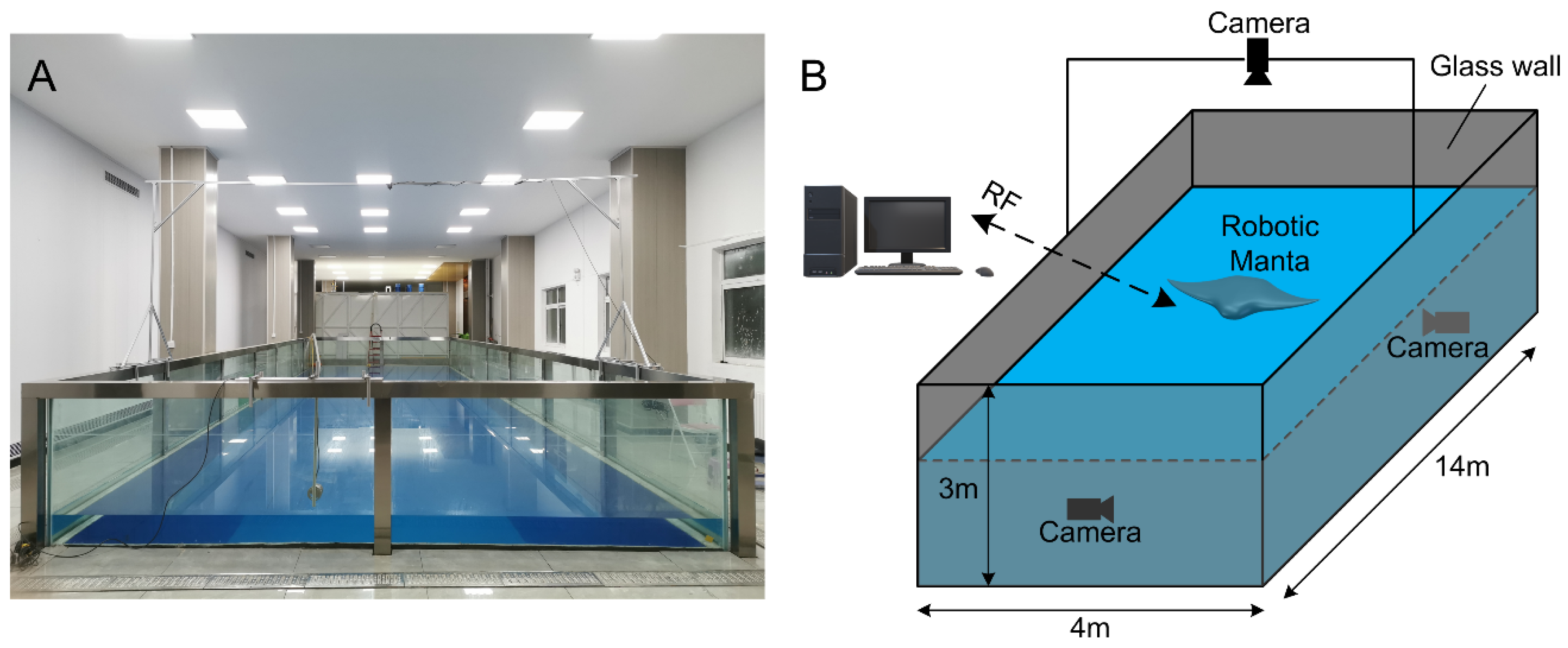
The Takagi-Sugeno (T-S) fuzzy model is a special fuzzy logic model suitable for application to systems that are locally linearized and capable of segmental control [29,30,31,32,33]. Compared with the Mandani fuzzy model, its output values are specific, eliminating the clarification step, and therefore more conducive to the quantitative study of the system [34,35]. Combining the T-S fuzzy model with BP neural network can reduce the workload of manual parameter identification to some extent and can also take advantage of the strengths of both methods.
The precise mathematical model of the robotic manta is difficult to establish, and the control effect exerted by the unique propulsion method on the vehicle needs further study. The T-S fuzzy neural network-based control method is not very sensitive to the model, so this method is used for the controller design of the manta ray imitation vehicle. In this paper, we decouple the depth and heading control of the robotic manta and design the depth and heading tracking controller based on a T-S fuzzy neural network, respectively.
The control input of the difference between the left and right pectoral fin phase difference is related to the heading deviation and the rate of change of heading, defined by the difference of the phase difference α = Δ φ 12 Δ φ 45 , according to which the following abstract equation is established
α = F ψ ( ψ e , r )
where F ψ ( ) is an abstract function; ψ e = ψ ψ d , ψ e is the heading error, ψ is the current heading angle, ψ d is the desired angle, and r is the rotated rate of heading.
The control input of the caudal fin angle is related to the depth difference and the depth change rate, according to which the following abstract equation is established
β = F z ( z e , v z )
where F z ( ) is an abstract function; z e = z z d , z e is the depth error, z is the current depth, z d is the desired depth, and v z is the vertical velocity of depth.
The main workload of the T-S fuzzy neural network-based controller design is the need for parameter identification based on the input-output data, and the identification is performed on the basis that sufficient data have been acquired. We first studied the motion characteristics of the robotic manta through experiments [36,37,38] and constructed a data set by classifying, processing, and calculating the acquired data. Then, the data set was used to train the network. The depth dataset takes the depth error and vertical velocity of depth as input and the caudal fin angle as output; the flow chart is shown in Figure 5A. The heading dataset takes the heading error and rotated rate of heading as input and the difference between left and right pectoral fin phase difference as output, as shown in Figure 5B.
It is obvious that this system is a Multi-Input Single-Output (MISO) system. The rules of output based on the T-S type fuzzy model are
R μ :   if   x 1   is   A 1 ν   and   x 2   is   A 2 ν ,   then   y μ = p 1 μ x 1 + p 2 μ x 2 + p 3 μ             μ = 1 , 2 , , 9 ; ν = 1 , 2 , 3
where R μ represents the fuzzy rule; x 1 and x 2 represent the inputs; A 1 ν and A 2 ν represent fuzzy sets of rule R μ ; y μ represent the output of rule R μ ; and   p 0 ν , p 1 ν , and p 2 ν represent the constants reflecting system characteristics.
When performing heading tracking, the input universe is x 1 = ψ e [ 180 ,   180 ] and x 2 = r [ 30 ,   30 ] , the output universe is Y = α [ 60 ,   60 ] . When performing depth tracking, the input universe is x 1 = z e [ 50 ,   50 ] and x 2 = v z [ 10 ,   10 ] , the output universe is Y = β [ 50 ,   50 ] . Each input theoretical universe is divided into three fuzzy subsets. Each fuzzy subset is matched with an affiliation function.
The structure of the T-S fuzzy neural network is shown in Figure 5C. The five-layer network structure consists of input, fuzzification, fuzzy inference, normalization, and output layers. Depending on the fuzzy control model utilized, the corresponding number of network layers is designed. The number of nodes in the first layer corresponds to the number of inputs. The number of nodes in the second layer is the sum of the fuzzy partitions of the inputs. The number of nodes in the third and fourth layers corresponds to the number of rules. The number of nodes in the fifth layer is the number of outputs.
The first layer consists of an input layer with two nodes. The inputs are directly connected to each node. Transferring input values to the nodes is its purpose.
The second layer consists of a fuzzification layer with six nodes. A fuzzy linguistic variable value is represented by a node. Its purpose is to calculate the subordination degree of each input belonging to the fuzzy set of each linguistic variable value. A Gaussian function is chosen for the subordination function
u n m = e ( x m c m n ) 2 2 σ m n 2 m = 1 , 2 , 3 ; n = 1 , 2
where n is the number of inputs; m is the number of fuzzy partitions x i ; c m n is the center value of the affiliation function; σ m n is the width of the affiliation function; and u n m is the affiliation value of each input belonging to the fuzzy set of values of each linguistic variable.
The third layer consists of a fuzzy inference layer with nine nodes. A node represents a fuzzy rule. Its purpose is to match the antecedents of fuzzy rules and compute the applicability of each rule
q μ = u 1 m u 2 m     μ = 1 , 2 , , 9 ;   m = 1 , 2 , 3
The fourth layer consists of a normalization layer with nine nodes. A node is connected to each of the third layer nodes, correspondingly, and represents a normalized value. Its purpose is to perform normalization calculations
q μ ¯ = q μ / s = 1 9 q s
The fifth layer consists of an output layer with one node. The node represents an explicit output and its purpose is to perform clarification calculations
Y = s = 1 9 y s q s ¯
where Y is the total output of the system.
The T-S fuzzy neural network structure is a combination of the T-S type fuzzy model and multilayer feedforward neural network, which adopts an error back propagation learning algorithm. This algorithm uses the total error of the network to adjust the weights to minimize the total error of the network, which is a process of error back propagation while correcting the weights. The center of mass and width of the affiliation function of each node in the fuzzification layer and the coefficient of the rule output are the parameters to be learned in the T-S fuzzy neural network. The error loss function can be described as
E = 1 2 ( y d Y ) 2
where y d denotes the desired output and Y denotes the actual output.
Then, it can be deduced that the learning algorithm for parameters c m n , σ m n , and p ν μ is
{ c m n ( k + 1 ) = c m n ( k ) λ E c m n   m = 1 , 2 , 3 ;   n = 1 , 2 σ m n ( k + 1 ) = σ m n ( k ) λ E σ m n   m = 1 , 2 , 3 ;   n = 1 , 2 p ν μ ( k + 1 ) = p ν μ ( k ) λ E p ν μ   ν = 1 , 2 , 3 ;   μ = 1 , 2 , , 9
where λ > 0 is the learning rate. At the end of the training, the above parameters are fixed.
We input the two data sets into the network separately for training. Taking the depth data as an example, the error curve of training 250 is shown in Figure 6A. The output curve of training 50 times is steeper than that of training 250 times.

4. Experiments

The improved CPG model and the controller are applied to the prototype of the robotic manta, and the effectiveness of the method is verified by experiments. The test was conducted in the general transparent water pool lab of Northwestern Polytechnical University in 2021. The pool is shown in Figure 7, its dimensions are 12 m × 4 m × 3 m. The test robotic manta is controlled by pectoral and caudal fins. The mechanical structure and electronic selection of the prototype are described carefully in Section 2. The computer software is written in C++ builder. Control programs are written in C language. The experiments are divided into two sets, a set of depth tracking and a set of heading depth tracking.

4.1. Depth Control Experiments

Depth control ability is an essential ability for underwater vehicles to perform tasks. The controller should ensure that the robotic manta can swim steadily at a certain depth underwater. Therefore, the basis of closed-loop control should be to ensure that the robotic manta can swim steadily at a certain depth underwater.
The specific process of the experiment is as follows: The PC sets and sends the target depth and related parameters, and the control system receives it. The depth information is fed back by the pressure sensor, and the depth error and the vertical velocity of depth are obtained through the processing of the single-chip microcomputer on the main control module, and the control value is calculated by the TS fuzzy neural network controller. The caudal fin changes the bias angle to adjust the pitch angle, thereby changing the depth of the robotic manta. The depth tracking experiments will be carried out from three aspects: a certain depth tracking experiment, a switching desire depth experiment, and an anti-interference experiment.
To verify the training effectiveness of the proposed controller, the first experiments were conducted. In this experiment, the robotic manta was controlled to track a specified depth, and the neural network was trained 250 times. The initial state of the robotic manta was floating on the water surface. The simplified parameters were set by PC, then the task was launched. The depth tracking stabilized and the depth was close to the desired depth, as shown in Figure 8A. From the data curve in Figure 8B, we can see that the initial water depth of the manta ray imitation underwater vehicle was 15 cm underwater, and the target depth was 50 cm; the target depth was reached in 3.6 s after the start of the task and it has no obvious overshoot phenomenon. The overshoot amount was 10 cm. The maximum pitch angle of the former was 22° and the vehicle can adjust to near 0° in time to maintain the current depth. Compared to the neural network that has only been trained 50 times, the vehicle reached the desired depth faster, with less overshoot, and better stability of pitch angle. It confirms the effectiveness of the training.
Meanwhile, we designed comparative experiments to verify the performance of the standard Mandani fuzzy method with the T-S fuzzy NN method. The relevant parameter settings of the Mandani fuzzy method are from [19]. The comparison results are illustrated in Figure 8C and indicate that both methods can quickly approximate the desired depth. The Mandani fuzzy controller took about 4.5 s to reach the desired depth, while the T-S fuzzy NN controller took about 5.0 s to reach the desired depth. However, after reaching the steady-state, the maximum depth error of the Mandani fuzzy was 9 cm, while the maximum depth error of the T-S Fuzzy NN method was 6 cm. For better quantitative analysis, we selected four relatively stable periods and calculated the root mean square error (RMSE) of the Mandani fuzzy method and T-S Fuzzy NN method. It was calculated that the RMSE of the Mandani fuzzy method was 4.01 and the RMSE of the T-S Fuzzy NN method was 2.55. Obviously, the proposed controller has better performance.
Then, to verify the consistency and stability of the controller, the robotic manta was controlled to track to two specified depths and it was repeated three times. In these repeated experiments, the neural network was trained 250 times. In each experiment, we selected four relatively stable periods and calculated the maximum error, mean error, and standard deviation for each segment as shown in Table 3. The data show that the maximum error was 6, and the mean errors were all within 3. The corresponding standard deviations were 2.89, 3.12, 3.36, 2.21, 2.54, and 2.46. The experimental errors were acceptable, which verified the viability, consistency, and stability of our method for depth tracking.
To further validate the stability and performance of the method, a second experiment was conducted. This experiment was divided into the following situations: the desired depth switched from 70 cm to 30 cm and the desired depth switched from 30 cm to 70 cm. The initial state of the robotic manta in the first part of the experiment was 8 cm in the water, when the robotic manta reached the depth of 70 cm and stabilized, the desired depth was switched to 30 cm. The desired depth was reached after 3 s without obvious overshoot. The overshoot was 3 cm, and a stable state was reached after 6 s. The error of the stable state was within 6 cm. The picture of depth change is shown in Figure 8D,E. From the data curve in Figure 8F, we can see that the initial state of the robotic manta in the second part of the experiment was 20 cm in the water, when the robotic manta reached the depth of 30 cm and stabilized, the desired depth was switched to 70 cm. The desired depth was reached after 5 s, the overshoot was 12 cm. The stable state was reached after 4 s, and the error of the stable state was within 6 cm. In summary, the robotic manta is capable of switching the desired depth quickly, reflecting the stability and rapidity of the proposed control method.
To ensure the performance of the proposed controller, depth anti-interference was conducted. When the robotic manta reached a stable stage, external disturbances were added. The curve of the interference applied during depth tracking is shown in Figure 8G. In this experiment, the disturbance was applied at 3.8–4.8 s and 3.8–5.2 s, respectively. The maximum depth at the end of jamming was 75 cm for the former and 77 cm for the latter. The vehicle was able to recover to the set depth at 3 s and 4 s, respectively, with a small overshoot. After 8 s, the depth reverted to the stable section, and the steady-state error was still within 6 cm. Thus, the stability and robustness of the proposed controller were demonstrated. The motion capture system in the literature [39,40] can be used to further complete the experiment.

4.2. Heading Control Experiments

Due to the asymmetry in the structure of the robotic manta, even if the left and right pectoral fins flap with the same motion parameters, there will still be a change in the heading angle. Maintaining a certain direction of continuous navigation is a necessary requirement for the robotic manta to accomplish its mission. Therefore, the closed-loop control of the heading is the most important thing for the robotic manta to achieve autonomous swimming.
To verify the performance and stability of the proposed controller for heading control, the heading tracking experiment was conducted. It is clearly demonstrated that the robotic manta does not have obvious heading changes and can keep swimming in the set heading, as shown in Figure 9A. The initial state of the robotic manta was 7° of heading angle and the target heading angle was set to 2°, respectively. After 2 s of the mission start, the heading angle of the vehicle was stable in the set heading without obvious overshoot, and the error was within 6°. During the heading angle stabilization phase, the heading angular velocities all fluctuated within 3°/s. The desired depth of the robotic manta was set to 50 cm, and the error was within 6 cm. This indicates that the vehicle can complete the heading and depth control to meet the accuracy at the same time, as shown in Figure 9B. This demonstrates the stability and excellent performance of the controller.
Meanwhile, to verify the repeatability of the experiments and the stability of the controller, four sets of repeated experiments were conducted. In these repeated experiments, the neural network was trained 250 times. In each experiment, we also selected four relatively stable periods and calculated the maximum error, mean error, and standard deviation for each segment as shown in Table 4. The data show that the maximum error was 5.72, and the mean errors were all within 2. The corresponding standard deviations were 1.64, 3.09, 2.86, and 0.47. The experimental errors were acceptable, which verified the validity and stability of our method for heading tracking.
Then, to further ensure the performance of the controller, the heading tracking anti-interference experiment was expanded. When the robotic manta reached the stable stage, external disturbances were added. The curve of the interference applied during the heading tracking is shown in Figure 9C,D. In this experiment, the disturbance was applied at 1.5–2.0 s and 1.1–2.0 s, respectively. The maximum heading angle at the end of jamming was 111° for the former and 145° for the latter. The vehicle was able to recover to the set depth after 3.9 s and 4.2 s, respectively. In general, the stability and robustness of the proposed control method were demonstrated.

5. Conclusions

In this paper, a CPG-driven network based on a phase oscillator model and a controller based on the TS fuzzy neural network is designed to track the depth and heading of the multi-stage fin pectoral fin structure of a robotic manta. The proposed CPG network can set the amplitude, frequency, phase difference, and the bias of the amplitude. Thus, the pectoral fins can use the bias to provide more lift and the caudal fin can be kept deflected to a certain angle to complete depth tracking. The T-S fuzzy neural network-based controller is the upper layer control of the CPG-driven network, specifically: based on the experimental data, the depth dataset and heading dataset are constructed, and the training of the established T-S fuzzy neural network is completed using the corresponding dataset, respectively. The depth and heading controller are proposed based on the CPG-driven network in which parameters are acquired by the T-S network. Finally, depth and heading experiments were conducted in the pool. The experimental results show that the depth control error was ± 6 cm and the heading control error was ± 6°.
In the future, we will study more high-precision swimming control methods. In order to achieve speed tracking and further autonomy of the robotic manta, we will actively integrate multiple types of sensors and build a more complete and powerful control system.

Author Contributions

Supervision, Y.C. (Yong Cao), Y.C. (Yonghui Cao), G.P. and Q.H.; Data Curation, Y.X. and Y.H.; Writing—original draft, Y.X.; Writing—review and editing, Y.X., Y.C. (Yonghui Cao) and Y.C. (Yong Cao). All authors have read and agreed to the published version of the manuscript.

Funding

This work was supported by the National Natural Science Foundation of China (Grant No. 52001260), the National Natural Science Foundation of China (Grant No. 51879220), and the National Key Research and Development Program of China (Grant No. 2020YFB1313200).

Institutional Review Board Statement

Not applicable.

Informed Consent Statement

Not applicable.

Data Availability Statement

Not applicable.

Conflicts of Interest

The authors declare no conflict of interest.

References

  1. Vu, M.T.; Le, T.H.; Thanh, H.L.N.N.; Huynh, T.T.; Van, M.; Hoang, Q.D.; Do, T.D. Robust position control of an over-actuated underwater vehicle under model uncer-tainties and ocean current effects using dynamic sliding mode surface and optimal allocation control. Sensors 2021, 21, 747. [Google Scholar] [CrossRef] [PubMed]
  2. Vu, M.T.; Le Thanh, H.N.N.; Huynh, T.-T.; Thang, Q.; Duc, T.; Hoang, Q.-D.; Le, T.-H. Station-Keeping Control of a Hovering Over-Actuated Autonomous Underwater Vehicle Under Ocean Current Effects and Model Uncertainties in Horizontal Plane. IEEE Access 2021, 9, 6855–6867. [Google Scholar] [CrossRef]
  3. Yuh, J. Design and Control of Autonomous Underwater Robots: A Survey. Auton. Robot. 2000, 8, 7–24. [Google Scholar] [CrossRef]
  4. Alam, K.; Ray, T.; Anavatti, S.G. A brief taxonomy of autonomous underwater vehicle design literature. Ocean. Eng. 2014, 88, 627–630. [Google Scholar] [CrossRef]
  5. Yu, J.; Chen, E.R.K.; Wang, S.; Wang, M. Progress and analysis of bionic robotic fish research. Control Theory Appl. 2003, 20, 485–491. [Google Scholar]
  6. Sfakiotakis, M.; Lane, D.M.; Davies, J.B.C. Review of fish swimming modes for aquatic locomotion. IEEE J. Ocean. Eng. 1999, 24, 237–252. [Google Scholar] [CrossRef] [Green Version]
  7. Wei, Q.P.; Wang, S.H.; Tan, M.; Wang, Y. Progress and analysis of bionic robotic fish research. Syst. Sci. Math. 2012, 32, 1274–1286. [Google Scholar]
  8. Wang, R.; Wang, S.; Wang, Y.; Cheng, L.; Tan, M. Development and Motion Control of Biomimetic Underwater Robots: A Survey. IEEE Trans. Syst. Man Cybern. Syst. 2020, 52, 833–844. [Google Scholar] [CrossRef]
  9. Yu, J.; Tan, M.; Chen, J.; Zhang, J. A Survey on CPG-Inspired Control Models and System Implementation. IEEE Trans. Neural Netw. Learn. Syst. 2013, 25, 441–456. [Google Scholar] [CrossRef]
  10. Yang, W.; Wu, P.; Zhou, X.; Zhu, P.; Liu, X. Central Pattern Generator Model Design and Gait Control Research of Amphibious Robotic Fish. In Proceedings of the Journal of Physics: Conference Series, London, UK, 5 March 2021; IOP Publishing: Bristol, UK, 2021; Volume 2029, p. 012109. [Google Scholar]
  11. Chen, Y.; Wang, T.; Wu, C.; Wang, X. Design, control, and experiments of a fluidic soft robotic eel. Smart Mater. Struct. 2021, 30, 065001. [Google Scholar] [CrossRef]
  12. Liu, J.; Zhang, C.; Liu, Z.; Zhao, R.; An, D.; Wei, Y.; Wu, Z.; Yu, J. Design and analysis of a novel tendon-driven continuum robotic dolphin. Bioinspir. Biomim. 2021, 16, 065002. [Google Scholar] [CrossRef]
  13. Chen, S.; Liu, Y.; Chen, T.; Lou, J. Rhythm motion control in bio-inspired fishtail based on central pattern generator. IET Cyber-Syst. Robot. 2021, 3, 53–67. [Google Scholar] [CrossRef]
  14. Chen, J.; Yin, B.; Wang, C.; Xie, F.; Du, R.; Zhong, Y. Bioinspired Closed-loop CPG-based Control of a Robot Fish for Obstacle Avoidance and Di-rection Tracking. J. Bionic Eng. 2021, 18, 171–183. [Google Scholar] [CrossRef]
  15. Wang, J.; Wu, Z.; Tan, M.; Yu, J. Controlling the depth of a gliding robotic dolphin using dual motion control modes. Sci. China Inf. Sci. 2020, 63, 1–14. [Google Scholar] [CrossRef]
  16. Wang, M.; Yu, J.; Tan, M.; Zhang, J. Multimodal swimming control of a robotic fish with pectoral fins using a CPG network. Chin. Sci. Bull. 2012, 57, 1209–1216. [Google Scholar] [CrossRef] [Green Version]
  17. Wu, Z.; Yu, J.; Su, Z.; Tan, M.; Li, Z. Towards an Esox lucius inspired multimodal robotic fish. Sci. China Inf. Sci. 2015, 58, 1–13. [Google Scholar] [CrossRef] [Green Version]
  18. Cao, Y.; Lu, Y.; Cai, Y.; Bi, S.; Pan, G. CPG-fuzzy-based control of a cownose-ray-like fish robot. Ind. Robot. Int. J. Robot. Res. Appl. 2019, 46, 779–791. [Google Scholar] [CrossRef]
  19. Alattas, K.A.; Mobayen, S.; Din, S.U.; Asad, J.H.; Fekih, A.; Assawinchaichote, W.; Vu, M.T. Design of a non-singular adaptive integral-type finite time tracking control for non-linear systems with external disturbances. IEEE Access 2021, 9, 102091–102103. [Google Scholar] [CrossRef]
  20. Thanh, H.L.N.N.; Vu, M.T.; Mung, N.X.; Nguyen, N.P.; Phuong, N.T. Perturbation Observer-Based Robust Control Using a Multiple Sliding Surfaces for Nonlinear Systems with Influences of Matched and Unmatched Uncertainties. Mathematics 2020, 8, 1371. [Google Scholar] [CrossRef]
  21. Morgansen, K.A.; Triplett, B.I.; Klein, D.J. Geometric Methods for Modeling and Control of Free-Swimming Fin-Actuated Un-derwater Vehicles. IEEE Trans. Robot. 2007, 23, 1184–1199. [Google Scholar] [CrossRef]
  22. Shen, F.; Cao, Z.; Zhou, C.; Xu, D.; Gu, N. Depth Control for Robotic Dolphin Based on Fuzzy PID Control. Int. J. Off-Shore Polar Eng. 2013, 23, 166–171. [Google Scholar]
  23. Yu, J.; Liu, J.; Wu, Z.; Fang, H. Depth Control of a Bioinspired Robotic Dolphin Based on Sliding-Mode Fuzzy Control Method. IEEE Trans. Ind. Electron. 2017, 65, 2429–2438. [Google Scholar] [CrossRef]
  24. Wei, Q.; Wang, S.; Wang, Y.; Zhou, C.; Tan, M. Course and depth control for a biomimetic underwater vehicle-RobCutt-I. Int. J. Off-Shore Polar Eng. 2015, 25, 81–87. [Google Scholar] [CrossRef]
  25. Yuan, J.; Wu, Z.; Yu, J.; Tan, M. Sliding Mode Observer-Based Heading Control for a Gliding Robotic Dolphin. IEEE Trans. Ind. Electron. 2017, 64, 6815–6824. [Google Scholar] [CrossRef]
  26. Gong, Z.; Cai, Y.; Bi, S.; Ma, H. Roll maneuver control of robotic fish propelled by oscillating pectoral fins. J. Beijing Univ. Aeronaut. Astronaut. 2015, 41, 2184. [Google Scholar]
  27. Fossen, T.I. Marine control systems–guidance, navigation, and control of ships, rigs and underwater vehicles. In Marine Cyber-Netics; TU Delft Publisher: Delft, The Netherlands, 2002; ISBN 8292356 002. [Google Scholar]
  28. Cao, Y.; Ma, S.; Xie, Y.; Hao, Y.; Zhang, D.; He, Y.; Cao, Y. Parameter Optimization of CPG Network Based on PSO for Manta Ray Robot. In Proceedings of the 2021 International Conference on Autonomous Unmanned Systems (ICAUS), Changsha, China, 24–26 September 2021; Springer: Berlin/Heidelberg, Germany, 2021; pp. 3062–3072. [Google Scholar]
  29. Chen, Z.; Zhang, B.; Stojanovic, V.; Zhang, Y.; Zhang, Z. Event-based fuzzy control for T-S fuzzy networked systems with various data missing. Neurocomputing 2020, 417, 322–332. [Google Scholar] [CrossRef]
  30. Mohanty, P.K.; Kundu, S.; Srivastava, S.; Dash, R.N. A New TS Model Based Fuzzy Logic Approach for Mobile Robots Path Planning. In Proceedings of the IEEE International Women in Engineering (WIE) Conference on Electrical and Computer Engineering (WIECON-ECE), Bhubaneswar, India, 26–27 December 2020; pp. 476–480. [Google Scholar]
  31. Wai, R.-J.; Yang, Z.-W. Adaptive Fuzzy Neural Network Control Design via a T–S Fuzzy Model for a Robot Manipulator Including Actuator Dynamics. IEEE Trans. Syst. Man Cybern. Part B (Cybern.) 2008, 38, 1326–1346. [Google Scholar] [CrossRef]
  32. Fan, Y.; An, Y.; Wang, W.; Yang, C. TS Fuzzy Adaptive Control Based on Small Gain Approach for an Uncertain Robot Manipula-tors. Int. J. Fuzzy Syst. 2020, 22, 930–942. [Google Scholar] [CrossRef]
  33. Vrkalovic, S.; Teban, T.A.; Borlea, I.D. Stable Takagi-Sugeno fuzzy control designed by optimization. Int. J. Artif. Intell. 2017, 15, 17–29. [Google Scholar]
  34. Li, J. Research on Robot Motion Control Based on Variable Structure Fuzzy Neural Network Based on TS Model. In Proceedings of the IOP Conference Series: Earth and Environmental Science, Changchun, China, 21–23 August 2020; IOP Publishing: Bristol, UK, 2020; Volume 440, p. 032090. [Google Scholar]
  35. Nguyen, A.T.; Taniguchi, T.; Eciolaza, L.; Campos, V.; Palhares, R.; Sugeno, M. Fuzzy control systems: Past, present and future. IEEE Comput. Intell. Mag. 2019, 14, 56–68. [Google Scholar] [CrossRef]
  36. Cao, Y.; Xie, Y.; Ma, S.; Zhang, D.; Hao, Y.; He, Y.; Cao, Y. Control of Robotic Manta Based on T-S Fuzzy Neural Network. In Proceedings of the 2021 International Conference on Autonomous Unmanned Systems (ICAUS), Changsha, China, 24–26 September 2021; Springer: Berlin/Heidelberg, Germany, 2021; pp. 2813–2822. [Google Scholar]
  37. Xing, C.; Cao, Y.; Cao, Y.; Pan, G.; Huang, Q. Asymmetrical Oscillating Morphology Hydrodynamic Performance of a Novel Bionic Pectoral Fin. J. Mar. Sci. Eng. 2022, 10, 289. [Google Scholar] [CrossRef]
  38. Hao, Y.; Cao, Y.; Cao, Y.; Huang, Q.; Pan, G. Course Control of a Manta Robot Based on Amplitude and Phase Differences. J. Mar. Sci. Eng. 2022, 10, 285. [Google Scholar] [CrossRef]
  39. Ma, N.; Yu, J.; Dong, X.; Axinte, D. Design and stiffness analysis of a class of 2-DoF tendon driven parallel kinematics mechanism. Mech. Mach. Theory 2018, 129, 202–217. [Google Scholar] [CrossRef]
  40. Wang, M.; Palmer, D.; Dong, X.; Alatorre, D.; Axinte, D.; Andy, N. Design and development of a slender dual-structure continuum robot for in-situ aeroengine repair. In Proceedings of the 2018 IEEE/RSJ International Conference on Intelligent Robots and Systems (IROS), Madrid, Spain, 1–5 October 2018; pp. 5648–5653. [Google Scholar]
Figure 1. The structure of robotic manta. (A) The structure and electronics distribution of robotic manta. (B) Silicone pectoral and caudal fins. (C) Prototype of robotic manta.
Jmse 10 00758 g001
Figure 2. The control system hardware structure. (A) Electronic composition. (B) Picture of the control system.
Jmse 10 00758 g002
Figure 3. The principle of basic motion. (A) The movements of pectoral and caudal fins. (B,C) The instructions of bias angle, where i = 1 , 2 , , 6 .
Jmse 10 00758 g003
Figure 4. The connection form and output curve of the CPG-driven network. (A) The connection form of the CPG-driven network. (B) The curve of the CPG-driven network output.
Jmse 10 00758 g004
Figure 5. The methods of CPG and T-S Fuzzy neural network-based Control of a Robotic Manta for depth and heading tracking. (A) The flow chart of controller design. (B) Schematic diagram of the datasets. (C) T-S fuzzy neural network structure diagram. (D) The control structure of the robotic manta.
Jmse 10 00758 g005
Figure 6. The error of training. (A) The curve of training error. (B) The curve of testing error.
Jmse 10 00758 g006
Figure 7. The transparent water pool. (A) The actual view of the pool. (B) The composition of the experimental system.
Jmse 10 00758 g007
Figure 8. The pictures and curves of depth tracking. (A) The pictures of tracking a specified depth. (B) The curve of tracking a specified depth. (C) Comparison of the Mandani fuzzy algorithm and T-S fuzzy NN algorithm. (D) The desired depth switched from 70 cm to 30 cm. (E) The desired depth switched from 30 cm to 70 cm. (F) The curve of depth switched. (G) The curves of the depth tracking anti-interference experiments.
Jmse 10 00758 g008
Figure 9. The picture and curves of heading tracking. (A) The picture of heading tracking. (B) The curves of heading tracking. (C) The curves of the first depth tracking anti-interference experiment. (D) The curves of the second depth tracking anti-interference experiment.
Jmse 10 00758 g009
Table 1. The technical specifications of the robotic manta.
ItemsSpecification
Dimension (L × W × H)600 mm × 800 mm × 150 mm
Mass8.00 kg
Actuator modeDC servomotors
Battery7.4-VDC 1500-mAH Ni-H
Micro-controllerSTM32F103ZET6
Inertial measurement unitSBG ELLIPSE2
SensorsPressure sensor, Laser sensors
Control modeRadio control (433 MHz)
Table 2. The parameters of the CPG-driven network.
Items Value   ( t   =   0   s ) Value   ( t   =   2.5   s ) Unit
A 1 = A 2 = A 3 = A 4 = A 5 = A 6 4040°
A 7 00°
f 1 = f 2 = f 3 = f 4 = f 5 = f 6 = f 7 0.40.4Hz
Δ φ 12 = Δ φ 23 030°
Δ φ 14 00°
Δ φ 45 = Δ φ 56 030°
X 1 = X 2 = X 3 = X 4 = X 5 = X 6 1010°
X 7 −35−55°
k a i 2020-
w i j 22-
Table 3. Error analysis of depth tracking.
Desired ValueMax ErrorAverage ErrorStandard Deviation
5061.422.89
6−0.173.12
6−0.193.36
8051.712.21
61.242.54
62.572.46
Table 4. Error analysis of heading tracking.
Desired ValueMAX ErrorAverage ErrorStandard Deviation
3403.651.311.64
235−5.72−0.893.09
1604.510.402.86
01.590.610.47
Publisher’s Note: MDPI stays neutral with regard to jurisdictional claims in published maps and institutional affiliations.

