Article

Defense Strategy against False Data Injection Attacks in Ship DC Microgrids

Marine Engineering College, Dalian Maritime University, Dalian 116026, China
*
Author to whom correspondence should be addressed.
J. Mar. Sci. Eng. 2022, 10(12), 1930; https://doi.org/10.3390/jmse10121930
Submission received: 30 October 2022 / Revised: 15 November 2022 / Accepted: 17 November 2022 / Published: 6 December 2022

Abstract

:
False Data Injection Attacks (FDIA) on ship Direct Current (DC) microgrids may result in the priority trip of a large load, a black-out, and serious accidents of ship collisions when maneuvering in the port. The key of the prevention of FDIA is the detection of and countermeasures to false data. In this paper, a defense strategy is developed to detect and mitigate against FDIA on ship DC microgrids. First, a DC bus voltage estimator is trained with an Artificial Neural Network (ANN) model. The error between the estimate value and the measure value is compared with a threshold generated from history data to detect the occurrence of FDIA. Combined with the correlation of artificial neural network inputs, bad data are identified and recovered. The method is tested under six cases with different network and physical disturbances in Matlab/Simulink. The results show that the method can identify and mitigate the FDIA effectively; the error of identifying FDIA by ANN is less than 0.5 V. Therefore, the deviation between the actual bus voltage and the reference voltage is less than 0.5 V.

1. Introduction

The ship’s microgrid is a small power generation and distribution system composed of a distributed power supply, an energy storage device, an energy conversion device and some important loads of the ship power grid. Among them, distributed power generation refers to a small power generation system mainly using clean energy or renewable energy [1].
Compared to Alternating Current (AC) grids, Direct Current (DC) grids have been an increasingly popular choice for ship electric system applications [2] due to their flexible operation, high power density, space saving and lack of synchronization.
At present, the energy management strategies applied to ship DC microgrids are roughly divided into centralized control, distributed control and hierarchical control. Hierarchical control combines the advantages of centralized control and distributed control. It has both a centralized controller and local controller. The centralized controller can realize the optimal control of the upper layer, and the local controller can realize the independent operation of each unit [1]. The hierarchical control consists of three layers. The goal of the primary control is to maintain the voltage stability. The droop control is used to adjust the output voltage and the power distribution between each converter. The secondary control is used to compensate the voltage drop generated by the primary control. The goal of the secondary control is to ensure that the power is transmitted according to the scheduling plan and that the average voltage is adjusted. Based on the secondary control, the tertiary control introduces a management strategy and optimization algorithm, sets the priority of load and formulates optimal operation strategies for different working conditions to regulate power quality [2,3].
The smart trend of ship DC microgrids leads to a more complex communication structure between the physical layer and control layer. This makes ship DC microgrids more vulnerable to cyberattacks.
The data of the communication network used by the supervisory control and data acquisition (SCADA) system are vulnerable to attacks because there is no firewall (because of the delay problem), the communication protocol lacks strong encryption and it is not updated to deal with the latest network security threats. Modern ship control systems use commercial off-the-shelf computing platforms [4].
Typical cyberattacks include False Data Injection Attacks (FDIA) [5], Man-In-The-Middle (MITM) attacks, Replay Attacks, Hijacking Attacks [6] and Denial of Service (DoS) attacks [7].
FDIA injects false measurement data into the communication network of the power grid, resulting in the deviation of the state estimation results, which affects the regulation of the controller and produces a wrong operation. The FDIA on a ship DC power grid may result in the priority trip of a large load, a black-out, and serious ship collision accidents when maneuvering in the port. In Ref. [4], the tertiary control of the ship’s power grid is attacked by FDIA; the objective of an attacker is to maximize the load curtailment during the cyber attack by redispatching the generators. To detect signs of malicious data, a multiagent system (MAS) that checks commands from the central energy management system is employed.
The Prevention of FDIA mainly focuses on a physical layer and a control layer. Firstly, physical sensors are protected from being intruded upon. Secondly, an intrusion detection strategy is developed in the control layer. Concretely, find and remove bad data from the network, and take consequence measures.
Figure 1 shows the power grid structure diagram of a ferry. The ship is 111 meters long, and the total battery capacity is 4160kWh and the power is 4.16MW. Diesel generators as standby power supply. The DC microgrid can be classified as a type of cyber-physical system (CPS) [8]. Many methods have been proposed to detect FDIA online in power-based CPSs (e.g., DC microgrids), such as dynamically changing the information structure, tracking the dynamic deviation of measurement data from historical data, a cumulative sum algorithm based on the generalized likelihood ratio estimation and a random game. The FDIA detection problem is reformulated in [9] as a problem of identifying changes in a list of inferred candidate invariants, where the invariants are the time-independent characteristics of the microgrid. The FDIA considered in [9] attempts to break the consensus protocol in a DC microgrid that is controlled based on a distributed control scheme. In addition, three methods are proposed in [9] to mitigate network attacks, namely, the attacked converter at the physical layer goes offline, the communication link between the attacked unit and the unattacked unit is disconnected and an improved control scheme is used to reduce the impact of FDIA. In Ref. [10], Signal Temporal Logic (STL) is proposed to detect two types of cyberattacks in DC microgrids, namely, FDIA and DoS, which are controlled in a distributed manner. Habibi et al. [11] trained a Recurrent Neural Network (RNN) to estimate the output DC voltage and current of the converter in order to detect FDIA in a DC microgrid by estimating the error. A method for identifying FDIA in DC microgrids is also suggested in [12], which models FDIA by conducting an extended analysis of the cooperative control network and taking into account the consensus theory. Additionally, in Ref. [13], FDIA tries to introduce false data into the existing measurement while proposing a decentralized approach to FDIA elimination that does not require data from other units. The suggested approach [13] introduces a secure control layer with a controller and RNN, which is implemented to give reference for applications that track references. Furthermore, Habibi et al. [14] introduced an efficient and appropriate strategy for ANN-based reference tracking applications to eliminate FDIA in DC microgrids. Furthermore, in Ref. [15], a decentralized neural network-based method is developed to detect and eliminate the FDIA of current measurements in DC microgrids, and the proposed strategy [15] has been studied on a DC microgrid consisting of distributed DC sources and controlled based on a consensus approach. Furthermore, in Ref. [16], the proposed method requires only one artificial neural network and is able to detect and mitigate False Data Injection Attacks (FDIA).
The existing research on the control layer intrusion detection strategy mainly focuses on the detection of FDIA and the isolation of physical devices that receive attacks. There are few studies on the attack resistance of the ANN and the recovering data tampered by FDIA.
This paper proposes an improved strategy to defend FDIA in DC microgrids. In this paper, the attacker’s target is the DC bus voltage, and the attack used is a false data injection attack. An ANN must be trained and utilized to determine the value of the DC bus voltage and input the data to the secondary controller. The method is implemented in a DC microgrid consisting of parallel DC-DC converters. Additionally, the strategy can also work in different scenarios, such as communication delay, load changes, some converters plugging in and out and ANN being attacked. When a certain input signal of ANN is injected with fake data, ANN can easily identify which input signal is attacked by relying on the linear correlation between the input data, and then ANN immediately stops accepting this input signal. The trained ANN can still work on the remaining data, but the accuracy of ANN’s estimation of the bus voltage is also reduced. To solve this issue, relying on the correlation between ANN input data, data recovery is performed on the attacked input, which improves the accuracy of ANN’s estimation of the bus voltage.
The remainder of this article is organized in the following manner. Section 2 introduces the ship DC microgrid model and the Anti-FDIA strategy. Section 3 presents the simulation results and analysis. Section 4 presents the summary of case studies. Finally, Section 5 summarizes the paper.

2. Anti-FDIA Model of the Ship DC Microgrid

2.1. Basic Features of an ANN

Artificial neural networks have become a popular area of study since the 1980s. Many applications have been developed, including the prediction of power loads and wind speeds [17], the weighting factor design of model predictive controllers for managing power converters [18], the detection of microgrid faults and their locations [19], the detection of network attacks on DC microgrids [20] and the optimization of power sharing in microgrids [21]. An ANN contains three levels: an input layer, a hidden layer and an output layer. The structure of an ANN with four inputs, two outputs and n hidden layer neural units is shown in Figure 2. The activation function output of the i-th neuron in the hidden layer of an ANN is calculated as:
a i = f 1 ( b 1 i + j = 1 n w 1 i , j × x j )
where a i , b 1 i , f 1 are the output, bias and activation function of the i-th neuron in the hidden layer, respectively. In addition, w 1 i , j is the weight of the j-th input x j of the i-th neuron in the hidden layer.
Formula (1) is expressed in the form of a matrix. Define W 1 as the weight matrix of the hidden layer of the ANN. Define B 1 as the bias vector.
W 1 = w 1 1 , 1 w 1 1 , 4 w 1 n , 1 w 1 n , 4
B 1 = [ b 1 1 ; b 2 1 ; ; b n 1 ]
The relationship between the output layer and the hidden layer is similar to the relationship between the hidden layer and the input layer. Consequently, the connection between the input and output is
Y = f 2 B 2 + W 2 f 1 B 1 + W 1 X

2.2. FDIA to DC Secondary Control

As shown in Figure 3, DC sources are connected in parallel to the DC bus through DC-DC converters, and droop control is used to distribute power. In order to maintain the DC bus voltage at the rated value, the secondary controller calculates the voltage drop Δu due to droop control and sends its value to the primary controller. The primary controller of unit i’s reference voltage is modified as follows:
u r i ( t ) = u d c + R D i i i ( t ) + Δ u ( t )
where u r i is the reference voltage of the i-th unit; u d c * is the reference DC bus voltage of the i-th unit; R D i is the droop coefficient of the i-th unit; i i is the output current of the i-th unit.
The secondary controller is a proportional-integral (PI) controller which is to maintain the DC bus voltage ( u d c ) at its reference value.
lim t u d c ( t ) = u d c *
FDIA at the secondary control layer is considered to make the DC bus voltage outside the allowable range, thereby shutting down the DC microgrid. If a system is being attacked, FDIA’s model can be taken into account as follows:
u a t = u d c t + u f t
If FDIA is present in the DC microgrid, replace u d c with u a . Therefore, in the case of an attack, (6) can be transformed into (8) as follows:
lim t u d c t + u f t = u d c
Therefore,
lim t u d c t = u d c lim t u f t
If the false data injected has a constant value α ( u f = α), the adjustment to (9) can be made as follows:
lim t u d c ( t ) = u d c * α
Therefore, according to (10), by adjusting the value of α, the DC bus voltage will converge to a value outside the allowable range, and the system can be shut down.

2.3. Detection and Mitigation Strategy

As shown in Figure 4, in order to detect the existence of false data, ANN is used to accurately estimate the value of the DC bus voltage. When the deviation between the measured DC bus voltage value and the value estimated by the ANN is larger than a certain threshold, it is considered that false data exist; otherwise, they do not exist. In order to eliminate the influence of false data, the estimated value of ANN is used to replace V a . Until the deviation between the value of the measured DC bus voltage and the estimated value of the ANN is less than a certain threshold, it is considered that the false data disappear and the system recovers. The inputs to the ANN use existing measurements, namely, the output voltage and current of each converter.
In addition, the input of the ANN includes the current value and historical value of the data, and the addition of the historical value helps the ANN to resist the noise interference of the input. The set of input data (X) and output data (Y) of the ANN is defined as follows:
X ( t ) = { u i ( t ) , i i ( t ) , u i ( t Δ t ) , i i ( t Δ t ) u i ( t D Δ t ) , i i ( t D Δ t ) | 1 i n }
Y ( t ) = u ¯ d c ( t )
where u i and i i are the output voltage and output current of the i-th bidirectional DC-DC converter, respectively. Additionally, u ¯ d c is the ANN’s estimate of the DC bus voltage. Further, D is the input memory order and Δt is the sampling time width. u ¯ d c will be calculated by the artificial neural network as follows:
u ¯ d c ( t ) = f 2 B 2 + W 2 f 1 B 1 + W 1 X ( t )
In order to implement the ANN online, the ANN is trained offline. In order to generate the training dataset, different operating conditions are considered. Then, as the system operates under different conditions (i.e., load changes), collect the sample needed to train the dataset. In addition, note that the main purpose of offline training is to ensure that the data collected for training are not from attack conditions. Therefore, these data are real.
If FDIA is present in the DC microgrid, replace u d c with u a . The ANN can estimate the bus voltage value through the output voltage and current of the bidirectional DC-DC converter and compare the measured bus voltage with the ANN estimate. The difference value obtained by the comparison is used to judge whether the bus voltage measurement value is injected with false data. If FDIA is present, replace u a with u ¯ d c . There is no need to estimate the value of the false data injected in the bus voltage value.
Since the primary control adopts droop control, there is a strong correlation between the output voltage of the converter and the output current. As shown in Formula (5), there is also a correlation between the output currents of n converters. In Formula (14), when the current sharing strategy is adopted, the ‘approximately equals’ sign becomes the ‘equals’ sign.
i 1 i 1 m a x i 2 i 2 m a x i n i n m a x
So, it is easy to identify if a certain input of the ANN is injected with false data. After identification, stop receiving this signal and estimate it by other inputs, which is similar to recovering lost data. For example, when the output current of unit j is injected with false data, the real value of the output current of unit j can be estimated by Formula (15). This greatly improves the robustness of the system regarding attacks.
i j ¯ = α × v j v d c Δ v R D j + β × i j max n 1 i = 1 , i j n i i i i max
where α + β = 1 and α and β are the weights, which are determined according to the degree of correlation between the input and the output.

3. Case Study and Discussion

The method is validated by simulating a ship DC microgrid consisting of four battery packsin the MATLAB/Simulink environment. The simulation step is 5e–5s. Additionally, each DER unit consists of a DC voltage source (500 V) and a bidirectional DC–DC converter, which will be connected to the DC bus through resistive wires. The topology of the bidirectional DC/DC converter used is a two-way Buck/Boost circuit. The switching frequency of the converter is 5 kHz. The output capacitance of the converter is 1000 μF. The droop coefficient ( R D ) in the droop control is 0.5. The reference value of the DC bus voltage is 1000 V. The values of the resistance lines are as follows: R1 = 0.02 Ω, R2 = 0.03 Ω, R3 = 0.04 Ω and R4 = 0.05 Ω. The communication delay for the secondary control data transmission is set to 100 ms. The proportional parameter and integral parameter of the secondary controller are set to 1. Before developing the ANN, it must be trained. Training the ANN requires samples. The DC microgrid model is built to run for 11 s, and the sampling time for data collection is 0.1 s. It is worth noting that the load changes while the model is running. Then, 101 input and output samples are taken. To collect comprehensive data, DC microgrids need to be operated under different conditions. The voltage drop provided by the secondary control also varies during the operation of the DC microgrid. The number of DC power and bidirectional converters connected to the DC microgrid is a variable number to allow for more dynamic data collection during the training phase. To test the suggested strategy, six case studies are taken into account, as show in Table 1.

3.1. Case Study 1: Slow Load Change

The purpose of this case is to demonstrate the effectiveness of the proposed method with continuously changing loads. The system is in a stable state before the first second, and then the load is increased by 30 kw/s. Figure 5b shows that, in order to maintain the stability of the bus voltage, the output current of the converter increases with the increase in the load. Figure 5a shows that the DC bus voltage remains stable, and the ANN can estimate the DC bus voltage well. The estimated value coincides with the waveform of the true value.

3.2. Case Study 2: Sudden Load Increase and Decrease

The purpose of this case is to show how the suggested strategy performs under extreme load variations. The system is in a stable state before the first second. At t = 4 s, add a 100 kw load to the DC microgrid. Then, the system reduces the load by 100 kw at t = 7 s. It can be seen from Figure 6b that, in order to maintain the stability of the bus voltage, the output current of the converter increases sharply at t = 4 s and decreases sharply at t = 7 s. It can be seen from Figure 6a that the error between the ANN estimated value and the actual value is within 0.5 V after the load changes drastically.

3.3. Case Study 3: Plug-and-Play of Additional Units

The purpose of this case is to test the suggested strategy under the plug-and-play of an additional unit. For this reason, the interruption of unit 4 occurs at t = 7 s. Figure 7 depicts the DC bus voltage and current of the device, respectively. After the 7th second, the output current of unit 4 is 0 A, and the output currents of other units increase. The ANN can successfully estimate the value of the bus voltage. The error is within 0.3 V.

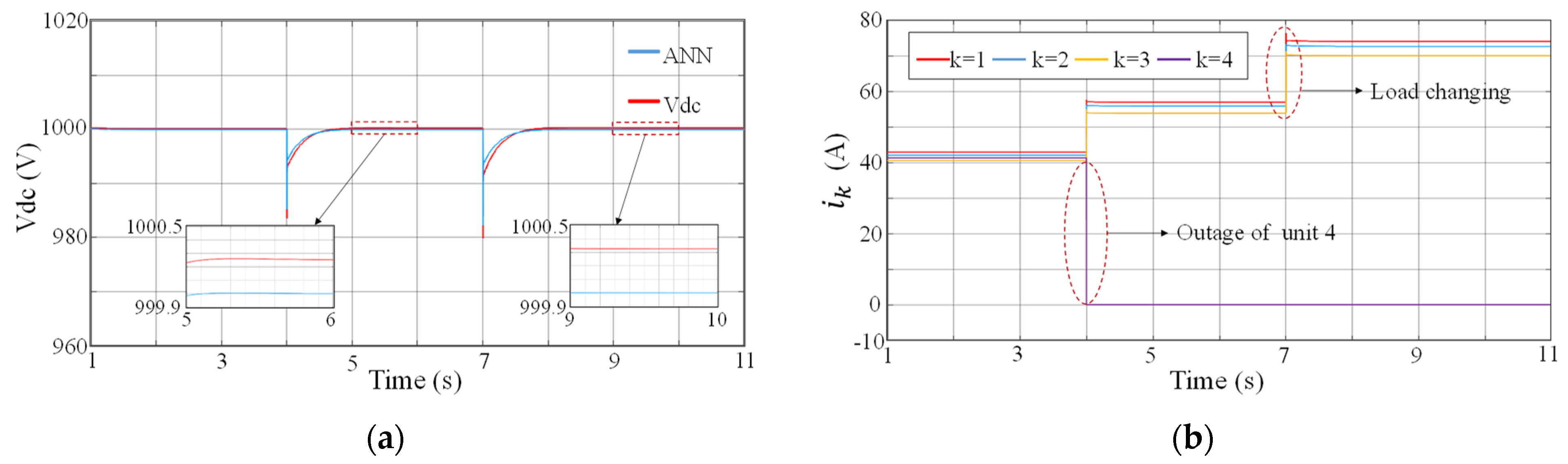
3.4. Case Study 4: Complex Situations

In this case, the suggested method-based ANN will be tested in more complex situations. The shutdown of unit 4 occurs at t = 4 s, and the load is added to the DC microgrid at t = 5 s. As shown in Figure 8. When the DC microgrid operates according to the proposed strategy, the ANN can still accurately estimate the bus voltage value, even if the system is in a state of a large load change or unit outage. The enlarged view of Figure 8a shows that the error in a steady state is less than 0.3 V.

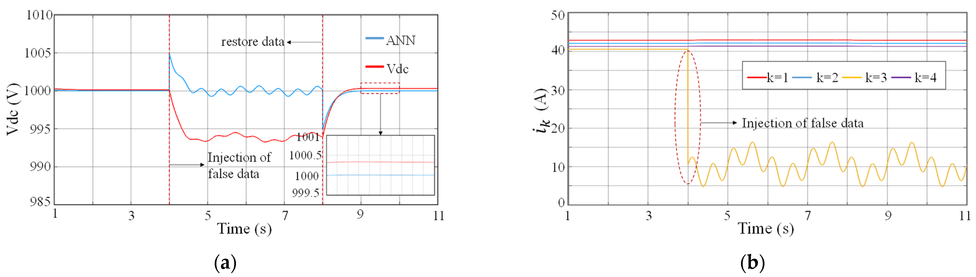
3.5. Case Study 5: Artificial Neural Network Is Attacked by FDIA

This case is to demonstrate the attack resistance of the proposed strategy. The ANN stops receiving the input signal when a specific input of an ANN is also attacked by FDIA. As seen in Figure 9, the system is in a steady state before the first second. At the fourth second, the input i 3 of the ANN is injected with false data, and the ANN immediately stops accepting the signal. At the seventh second, the input i 4 of the ANN is also injected with false data, and the ANN immediately stops accepting the signal. Even if the ANN has been taught with data, when it is attacked, it can still estimate the bus voltage value by depending on the remaining data, but the error has grown, and the highest error is roughly 1.5 V.

3.6. Case Study 6: Data Recovery

The goal of this case is to demonstrate the feasibility of the data recovery strategy when an ANN is attacked. The system is in a stable state before the first second. The artificial neural network input i 3 is attacked by false data injection at the fourth second, as shown in Figure 10a. The estimated output of the bus voltage seriously deviates from the actual value. It is detected that the output current of unit 3 is attacked by false data injection. At the eighth second, the ANN stops accepting the output current signal of unit 3, it is estimated by other inputs that are not attacked by false data injection through (15) and the estimated value is input to artificial neural networks. The ANN can also accurately estimate the DC bus voltage value. As shown in Figure 10a, the estimated value differs from the true value by less than 0.5 V.

4. The Summary of the Case Studies

Through six case studies, it is found that the trained ANN can not only accurately estimate the bus voltage value under various physical disturbances but also has a certain anti-attack ability and can still work by relying on some data. Although the ANN can still work with some inputs, the estimation ability of the bus voltage has decreased, and the deviation between the actual value and the estimated value has increased. However, by repairing the attacked data, the error is reduced.

5. Conclusions

In this paper, a defense strategy is developed to detect and mitigate against FDIA on ship DC microgrids. The technique is based on ANN, and the DC bus voltage value may be precisely calculated by the ANN. The DC power grid is then assessed to see if it has been attacked by false data injection based on the error between the value estimated by the ANN and the real value. When under attack, the secondary controller uses the calculated number as the input rather than having to figure out how much false data are injected and consider how they changed. This brings the complexity down. In any situation, even under the influence of FDIA, the trained ANN can accurately estimate the voltage value of the DC bus and identify and correct the false data according to the correlation between inputs. Under various disturbances, the estimated deviation of the ANN to the bus voltage is less than 0.5 V, while the influence of a 0.5 V DC bus voltage deviation on the ship power grid can be ignored. The deficiency is the lack of experimental content, which will be reflected in the future work.

Author Contributions

Conceptualization, Y.Z. and H.Z.; methodology, Y.Z.; software, Y.Z.; formal analysis, Y.Z.; investigation, Y.Z.; resources, J.Z.; writing—original draft preparation, Y.Z. and H.Z.; writing—review and editing, Y.Z. and T.W. All authors have read and agreed to the published version of the manuscript.

Funding

This research was supported by a grant from the High Technology Ship Research and Development Program of the Ministry of Industry and Information Technology of China (CJ02N20).

Institutional Review Board Statement

Not applicable.

Informed Consent Statement

Not applicable.

Data Availability Statement

Not applicable.

Conflicts of Interest

The authors declare no conflict of interest.

Nomenclature

Indices and Sets
FDIAFalse Data Injection Attacks
DCDirect Current
ANNArtificial Neural Network
ACAlternating Current
SCADASupervisory control and data acquisition
MITMMan-In-The-Middle attack
DoSDenial of Service
MASMultiagent system
CPSCyber-physical system
STLSignal Temporal Logic
RNNRecurrent Neural Network
DERDistributed energy resources
W 1 Weight matrix of the hidden layer of the ANN
B 1 Bias vector of the ANN
u d c * The reference DC bus voltage
u d c DC bus voltage
u ¯ d c The ANN’s estimate of the DC bus voltage

References

  1. Qiang, S.; Chen, Q. Hierarchical control of direct current microgrid on ship. Science Technol. Eng. 2020, 20, 10979–10988. [Google Scholar]
  2. Xu, L.; Guerrero, J.M.; Lashab, A.; Wei, B.; Bazmohammadi, N.; Vasquez, J.C.; Abusorrah, A. A Review of DC Shipboard Microgrids Part II: Control Architectures, Stability Analysis and Protection Schemes. IEEE Trans. Power Electron. 2022, 37, 4105–4120. [Google Scholar] [CrossRef]
  3. Guerrero, J.M.; Vasquez, J.C.; Matas, J.; de Vicuna, L.G.; Castilla, M. Hierarchical control of droop-controlled AC and DC microgrids—A general approach toward standardization. IEEE Trans. Ind. Electron. 2010, 58, 158–172. [Google Scholar] [CrossRef]
  4. Kushal, T.R.B.; Lai, K.; Illindala, M.S. Risk-based mitigation of load curtailment cyber attack using intelligent agents in a shipboard power system. IEEE Trans. Smart Grid 2018, 10, 4741–4750. [Google Scholar] [CrossRef]
  5. Liu, Y.; Ning, P.; Reiter, M.K. False data injection attacks against state estimation in electric power grids. ACM Trans. Inf. Syst. Secur. (TISSEC) 2011, 14, 1–33. [Google Scholar] [CrossRef]
  6. Sahoo, S.; Peng, J.C.H.; Mishra, S.; Dragičević, T. Distributed screening of hijacking attacks in DC microgrids. IEEE Trans. Power Electron. 2019, 35, 7574–7582. [Google Scholar] [CrossRef]
  7. Hussain, B.; Du, Q.; Sun, B.; Han, Z. Deep learning-based DDoS-attack detection for cyber–physical system over 5G network. IEEE Trans. Ind. Inform. 2021, 17, 860–870. [Google Scholar] [CrossRef]
  8. Bolbot, V.; Theotokatos, G.; Bujorianu, L.M.; Boulougouris, E.; Vassalos, D. Vulnerabilities and safety assurance methods in Cyber-Physical Systems: A comprehensive review. Reliab. Eng. Syst. Saf. 2019, 182, 179–193. [Google Scholar] [CrossRef] [Green Version]
  9. Beg, O.A.; Johnson, T.T.; Davoudi, A. Detection of false-data injection attacks in cyber-physical DC microgrids. IEEE Trans. Ind. Inform. 2017, 13, 2693–2703. [Google Scholar] [CrossRef]
  10. Beg, O.A.; Nguyen, L.V.; Johnson, T.T.; Davoudi, A. Signal temporal logic-based attack detection in DC microgrids. IEEE Trans. Smart Grid 2019, 10, 3585–3595. [Google Scholar] [CrossRef]
  11. Habibi, M.R.; Baghaee, H.R.; Dragičević, T.; Blaabjerg, F. Detection of false data injection cyber-attacks in DC microgrids based on recurrent neural networks. IEEE J. Emerg. Sel. Top. Power Electron. 2020, 9, 5294–5310. [Google Scholar] [CrossRef]
  12. Sahoo, S.; Peng, J.C.H.; Devakumar, A.; Mishra, S.; Dragičević, T. On detection of false data in cooperative DC microgrids—A discordant element approach. IEEE Trans. Ind. Electron. 2019, 67, 6562–6571. [Google Scholar] [CrossRef]
  13. Habibi, M.R.; Dragicevic, T.; Blaabjerg, F. Secure control of dc microgrids under cyber-attacks based on recurrent neural networks. In Proceedings of the 2020 IEEE 11th International Symposium on Power Electronics for Distributed Generation Systems (PEDG), Dubrovnik, Croatia, 28 September 2020–1 October 2020; pp. 517–521. [Google Scholar]
  14. Habibi, M.R.; Baghaee, H.R.; Dragičević, T.; Blaabjerg, F. False data injection cyber-attacks mitigation in parallel DC/DC converters based on artificial neural networks. IEEE Trans. Circuits Syst. II Express Briefs 2020, 68, 717–721. [Google Scholar]
  15. Habibi, M.R.; Sahoo, S.; Rivera, S.; Dragičević, T.; Blaabjerg, F. Decentralized coordinated cyberattack detection and mitigation strategy in DC microgrids based on artificial neural networks. IEEE J. Emerg. Sel. Top. Power Electron. 2021, 9, 4629–4638. [Google Scholar] [CrossRef]
  16. Habibi, M.R.; Baghaee, H.R.; Blaabjerg, F.; Dragičević, T. Secure Control of DC Microgrids for Instant Detection and Mitigation of Cyber-Attacks Based on Artificial Intelligence. IEEE Syst. J. 2021, 16, 2580–2591. [Google Scholar] [CrossRef]
  17. Jawad, M.; Ali, S.M.; Khan, B.; Mehmood, C.A.; Farid, U.; Ullah, Z.; Usman, S.; Fayyaz, A.; Jadoon, J.; Tareen, N.; et al. Genetic algorithm-based non-linear auto-regressive with exogenous inputs neural network short-term and medium-term uncertainty modelling and prediction for electrical load and wind speed. J. Eng. 2018, 2018, 721–729. [Google Scholar] [CrossRef]
  18. Dragičević, T.; Novak, M. Weighting factor design in model predictive control of power electronic converters: An artificial neural network approach. IEEE Trans. Ind. Electron. 2018, 66, 8870–8880. [Google Scholar] [CrossRef] [Green Version]
  19. Ali, Z.; Terriche, Y.; Abbas, S.Z.; Abbas, S.Z.; Hassan, M.A.; Sadiq, M.; Su, C.-L.; Guerrero, J.M. Fault Management in DC Microgrids: A Review of Challenges, Countermeasures, and Future Research Trends. IEEE Access 2021, 9, 128032–128054. [Google Scholar] [CrossRef]
  20. Mohammadpourfard, M.; Weng, Y.; Genc, I.; Kim, T. An Accurate False Data Injection Attack (FDIA) Detection in Renewable-Rich Power Grids. In Proceedings of the 2022 10th Workshop on Modelling and Simulation of Cyber-Physical Energy Systems (MSCPES), Milan, Italy, 3 May 2022; pp. 1–5. [Google Scholar]
  21. Baghaee, H.R.; Mirsalim, M.; Gharehpetian, G.B. Power calculation using RBF neural networks to improve power sharing of hierarchical control scheme in multi-DER microgrids. IEEE J. Emerg. Sel. Top. Power Electron. 2016, 4, 1217–1225. [Google Scholar] [CrossRef]
Figure 1. Power grid Structure diagram of a ferry.
Jmse 10 01930 g001
Figure 2. Architecture of the ANN.
Jmse 10 01930 g002
Figure 3. Control Hierarchy of the DC microgrid.
Jmse 10 01930 g003
Figure 4. Implementation of an anti-FDIA strategy based on the ANN.
Jmse 10 01930 g004
Figure 5. (a) Values of DC bus voltage and ANN output in case study 1; (b) Values of currents of the bidirectional DC-DC converters in case study 1.
Jmse 10 01930 g005
Figure 6. (a) Values of DC bus voltage and ANN output in case study 2; (b) Values of currents of the bidirectional DC-DC converters in case study 2.
Jmse 10 01930 g006
Figure 7. (a) Values of DC bus voltage and ANN output in case study 3; (b) Values of currents of the bidirectional DC-DC converters in case study 3.
Jmse 10 01930 g007
Figure 8. (a) Values of DC bus voltage and ANN output in case study 4; (b) Values of currents of the bidirectional DC-DC converters in case study 4.
Jmse 10 01930 g008
Figure 9. Values of DC bus voltage and ANN output in case study 5.
Jmse 10 01930 g009
Figure 10. (a) Values of DC bus voltage and ANN output in case study 6; (b) Values of currents of the bidirectional DC-DC converters in case study 6.
Jmse 10 01930 g010
Table 1. Case Study Preview.
Case Study NumberPlaned ScenarioNumber of Units
1slow load change4
2sudden load increase and decrease4
3plug-and-play of additional units4
4complex situations4
5ANN is attacked by FDIA4
6data recovery4
Publisher’s Note: MDPI stays neutral with regard to jurisdictional claims in published maps and institutional affiliations.

