Article

Supercritical CO2 Power Cycle and Ejector Refrigeration Cycle for Marine Dual Fuel Engine Efficiency Enhancement by Utilizing Exhaust Gas and Charge Air Heat

1
Marine Engineering College, Dalian Maritime University, Dalian 116026, China
2
National Center for International Research of Subsea Engineering Technology and Equipment, Dalian Maritime University, Dalian 116026, China
3
School of Electrical and Electronic Engineering, Nanyang Technological University, 50 Nanyang Avenue, Singapore 639798, Singapore
*
Authors to whom correspondence should be addressed.
J. Mar. Sci. Eng. 2022, 10(10), 1404; https://doi.org/10.3390/jmse10101404
Submission received: 16 August 2022 / Revised: 18 September 2022 / Accepted: 24 September 2022 / Published: 1 October 2022
(This article belongs to the Special Issue Decarbonization of Ship Power Plants)

Abstract

:
Dual fuel engines with LNG as fuel have become a feasible solution for ship power units in the current situation, but their fuel efficiency needs to be further enhanced to meet the increasingly stringent emission requirements. This paper designs a dual-loop system, including a supercritical CO2 power cycle and a thermally driven ejector refrigeration cycle, for recovering the exhaust gas and charge air heat of a marine dual fuel engine. The models of the waste heat recovery system, the evaluation indicators of the combined system, and the genetic algorithm optimization program are developed. Compared to the standalone machine, the waste heat recovery system can improve by about 9.3% of the engine’s fuel efficiency. The performance analysis shows that the ejector contributes to the highest share of exergy destruction and accounts for approximate 53% of the refrigeration cycle. There are optimal values for the compressor inlet temperature of about 8.1 MPa and for the turbine inlet temperature of about 305 °C. Finally, after optimization, the specific fuel consumption, fuel efficiency, and CO2 emissions of the combined system are around 137.9 g/kWh, 53.3%, and 537.4 g/kWh, respectively. It provides a feasible solution in which the charge air cooler can be wholly replaced by the ejector refrigeration cycle.

1. Introduction

Global industry is expected to bring about technological change to prevent environmental pollution and global warming crises, as well as to address fluctuating fuel prices [1]. For the international transportation industry, there is no other more dominant mode than shipping, as almost 80–90% of all international cargo is transmitted by sea [2]. The greenhouse gas (GHG) emissions from the shipping industry account for more than 4.3% of global emissions [3]. On the other hand, to mitigate the impact of shipping on the environment, the International Maritime Organization (IMO) has proposed the Energy Efficiency Design Index (EEDI) to demand fuel efficiency on new and existing vessels [4]. Therefore, marine energy conservation and emissions reduction are serious issues that must be addressed sooner rather than later.
Marine diesel engines have been widely applied on vessels as the prime movers for propulsion and auxiliary genset [5]. The use of alternative fuels, such as methanol [6], ethanol [7], and hydrogen, in marine engines is an essential option to reduce shipboard emissions. However, due to safety concerns and cost effectiveness problems, they do not seem to be preferable currently [8]. Liquefied natural gas (LNG), as a relatively clean fossil fuel, is becoming the transition fuel on the path to zero-carbon ships [9]. Compared with traditional marine fuels, it is an effective way to save fuel consumption and mitigate environmental pollution. It hardly produces any SOX emissions and significantly reduces NOX emissions, and there is also an elimination of around 25% in carbon dioxide (CO2) emissions [8]. Therefore, LNG-fueled ships equipped with marine dual fuel engines have developed rapidly in recent years [10]. However, there is no single route to fully decarbonizing the maritime industry. Because marine engines with LNG as fuel cannot meet the 50% CO2 emissions reduction target without further improvement, a multifaceted response is required [11].
For a heavy-duty marine engine, about half of the fuel energy input is discharged into the environment from waste heat (e.g., exhaust gas, charge air, and jacket water) [12]. Accordingly, waste heat recovery (WHR) technology has been recognized as one of the most efficient ways to improve an engine’s fuel efficiency and reduce CO2 emissions for vessels [13]. On the other hand, compared to automotive applications, marine engines have a more stable operating profile. Thus, the relatively stable waste heat is easier to recover [14]. Under these circumstances, the thermodynamic cycle, as the bottoming cycle of marine engines, has been studied extensively [15]. The single-pressure steam Rankine cycle (SRC) has been studied to replace the exhaust steam boiler for harvesting the exhaust gas heat of marine engines. Uusitalo A et al. [16] adopted the SRC with four stages of a 1 MW-scale radial outflow turbine for exhaust gas heat recovery in cruise ships. Liang et al. [17] considered using the engine jacket water to preheat the pump outlet working fluid of an SRC to increase its output power. Liu et al. [18] utilized an SRC with the engine jacket water as its working fluid to reclaim the exhaust gas heat, and they found that the fuel efficiency of the marine engine can be boosted by more than 2.5% at 100% engine load.
As the space of a ship’s cabin is limited and the exhaust gas temperature of the low-speed turbocharged marine diesel engine is relatively low, some scholars consider the organic Rankine cycle for its waste heat recovery. Song et al. [19] compared two separated ORC with a single ORC for the simultaneous recovery of the exhaust gas and jacket water waste heat of a marine engine. Their conclusion showed that the output work of the dual-loop ORC is 1.4% higher than the single cycle. Zhu et al. [20] carried out a thermoeconomic analysis of a combined system integrated with a turbocharged marine diesel engine and an ORC. Sung T and Kim K C [21] designed a dual-loop ORC for recovering the energy of the engine exhaust gas, jacket water, and LNG cold, and they concluded that the system could improve the power output of the marine dual fuel engine by 5.17%. An integrated dual-loop ORC for extracting a marine engine exhaust gas heat was proposed by Civgin M G and Deniz C [22]. The results showed that when the working fluids of the dual loop are cyclohexane and R1234ze, the output performance of the WHR system is best.
The temperature of the dual fuel engine exhaust gas in the gas fuel mode is relatively higher than that in the liquid fuel mode, even after the turbocharger, due to the natural gas having a much higher flash point than diesel. The use of ORC to directly recover the exhaust gas heat has the risk of decomposing the working fluids [23]. The supercritical CO2 power cycle (SCPC) has the characteristics of thermal stability, high efficiency, compactness, and economy. In recent years, it has been widely employed for the waste heat recovery of internal combustion engines [24]. Zhang et al. [25] conducted a thermodynamic optimization of their own designed SCPC for utilizing engine exhaust heat. Li et al. [26] analyzed the off-design performance of an SCPC for recovering the jacket water and exhaust gas heat based on the engine’s operational profile. For the efficient harvest of the waste heat of an internal combustion engine’s jacket water and exhaust gas, Song et al. [23] upgraded a preheating SCBC and proved that it could improve the output work by 7.4%. Dedicated to saving the fuel consumption of an ocean-going vessel, Pan et al. [27] employed an SCPC with a recompression layout for exhaust gas waste heat utilization. Through optimization, they stated that the SCPC could enhance the engine efficiency by 3.23%. However, when the heat source temperature was lower, the recuperative layout of an SCPC with a simple structure proved to have a better waste heat recovery performance than the recompression cycle.
To meet the multiple energy requirements of electricity and cooling capacity, some scholars considered the integrated cooling and power system driven by engine waste heat. Wu et al. [28] performed a thermodynamic analysis of an engine cooling water heat-driven absorption refrigeration cycle (ARC) to enhance the performance of an SCPC driven by the exhaust gas heat, and they stated that the SCPC’s cycle efficiency can be raised by at least 9.8%. Xia et al. [29] employed an SCPC and a thermally driven ejector refrigeration cycle (TERC) for engine exhaust gas waste heat cascade utilization. Huang et al. [30] adopted an SCPC and an ORC combined cycle and a TERC to recover the energy carried by cooling water and flue gas, which are not utilized by an engine. Wu et al. [31] designed an SCPC and an absorption refrigeration cycle combined system to harvest the engine exhaust gas waste heat. For marine applications, Wang et al. [
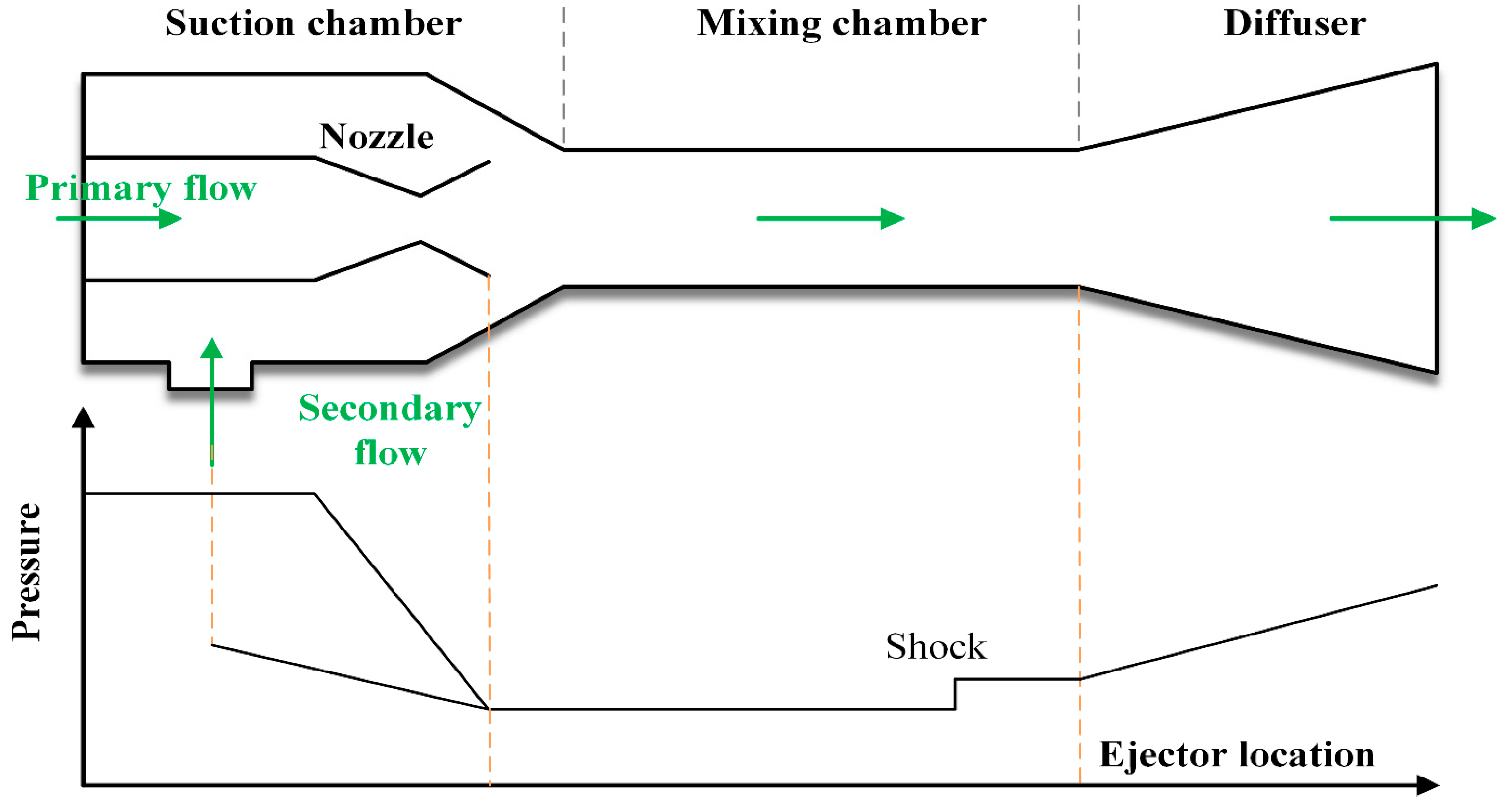
32] proposed four combined SCPC and ARC systems driven by marine diesel engine exhaust gas. They compared the performance of these systems and stated that the capital payback period of the best case is 6.85 years. Among these two thermal-driven refrigeration systems, due to the ARC having the disadvantages of high investment cost, large size, and corrosivity, the more inexpensive and compact TERC is recommended for shipboard waste heat recovery [15].
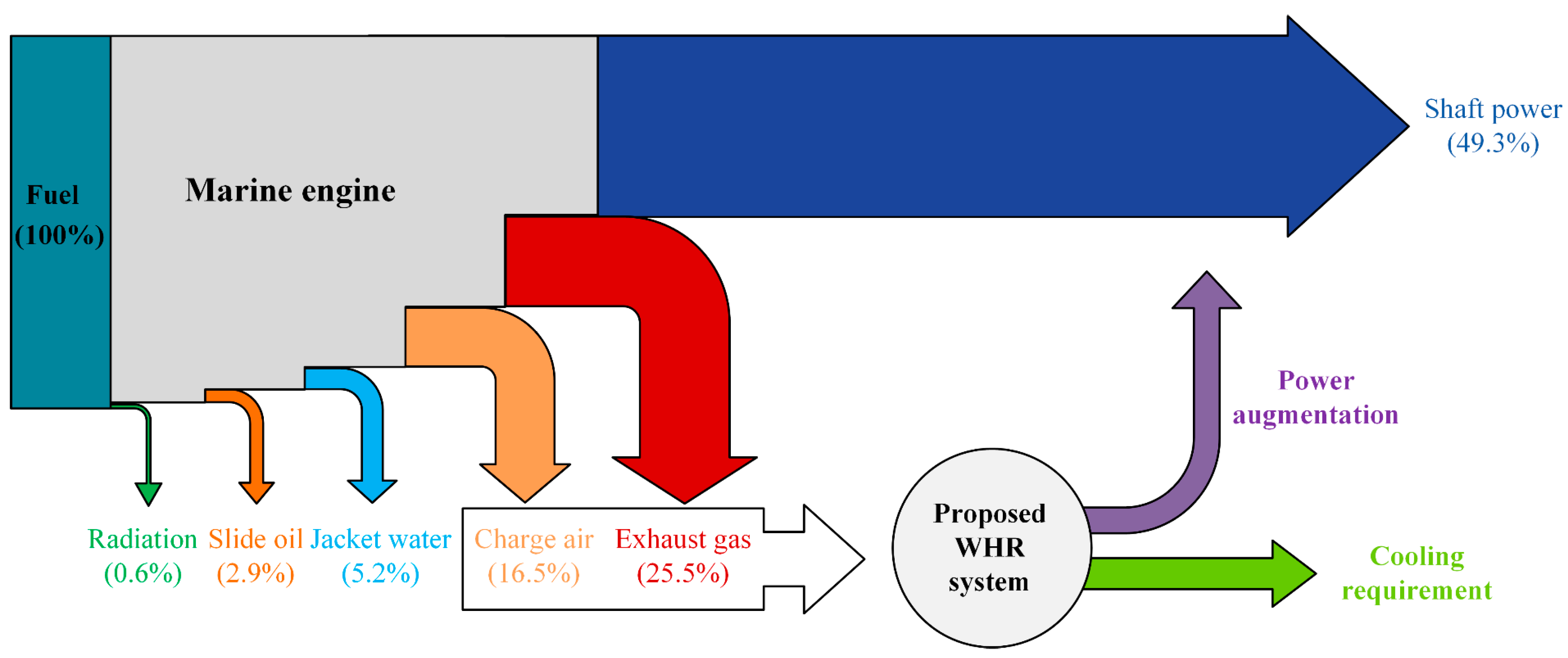
From the perspective of the marine engine waste heat type, most of the studies mentioned above focus on exhaust gas and jacket water heat utilization. However, for large-scale marine engines, the waste heat of jacket water is inferior to the charge air heat in terms of energy quantity and quality. Figure 1 displays the heat balance of a marine engine under full load [12]. It can be seen that the exhaust gas and charge air heat together account for more than 80% of the engine waste heat and 42% of the fuel energy. These two types of waste heat have the most valuable recovery potential for the marine engine’s fuel efficiency improvement. On the other hand, from the viewpoint of energy output type, few studies simultaneously consider the shipboard electricity and cooling capacity requirements.
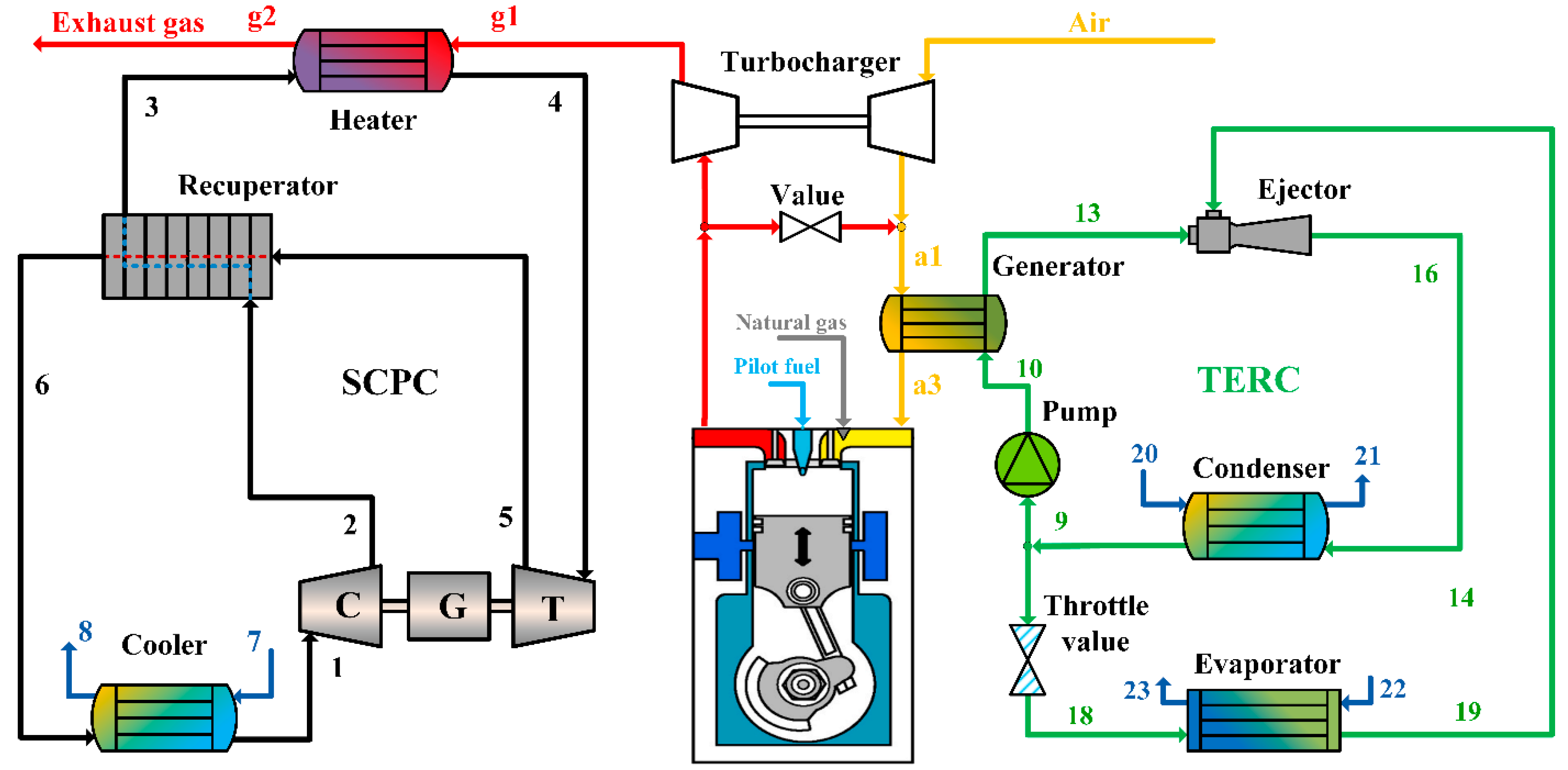
In this study, in order to meet the increasingly stringent emission requirements, a combined WHR system including an SCPC and a TERC is proposed for improving the overall energy efficiency of a marine dual fuel engine. In addition, the marine engine main waste heat of exhaust gas and charge air is set as the source of energy recovery, and the target needs of marine refrigeration and power are considered. Therefore, the WHR system is designed to harvest the main waste heat of the engine for shipboard power augmentation and refrigerating capacity production, which are needed the most. The motivation and purpose of this work are also demonstrated in 
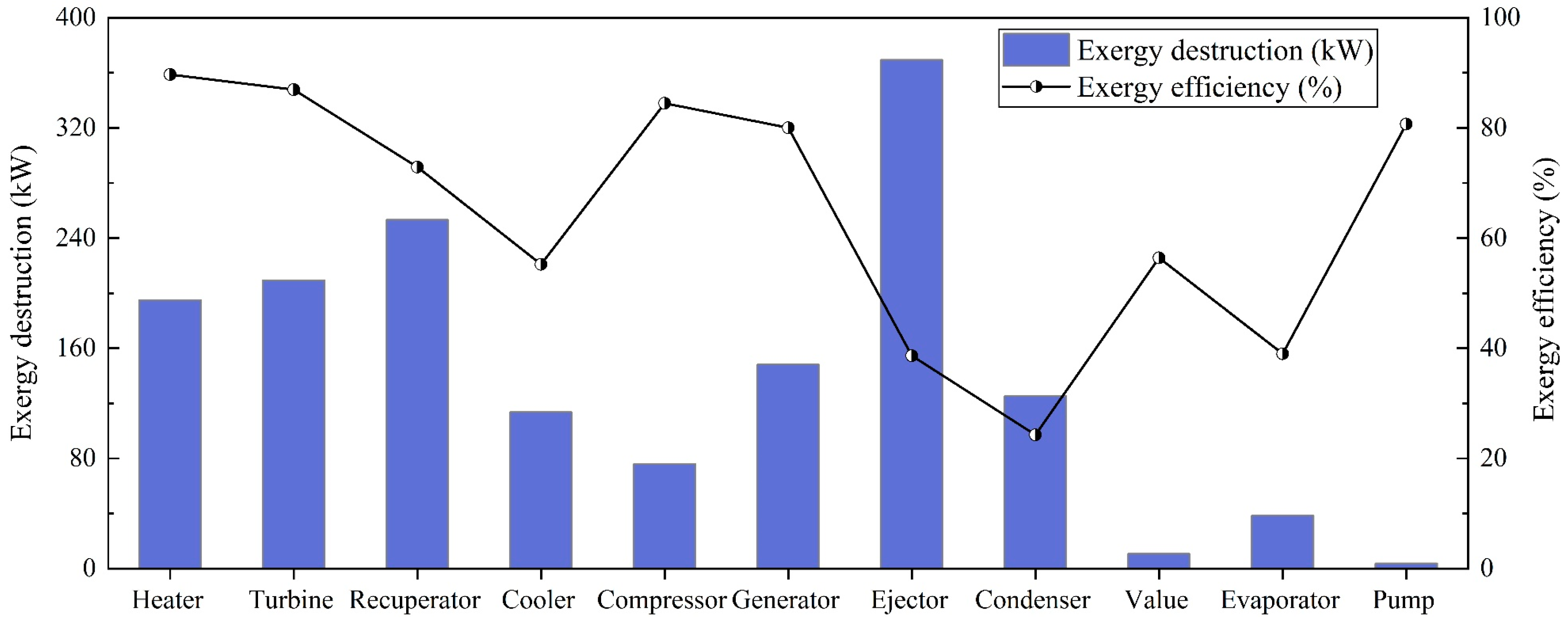
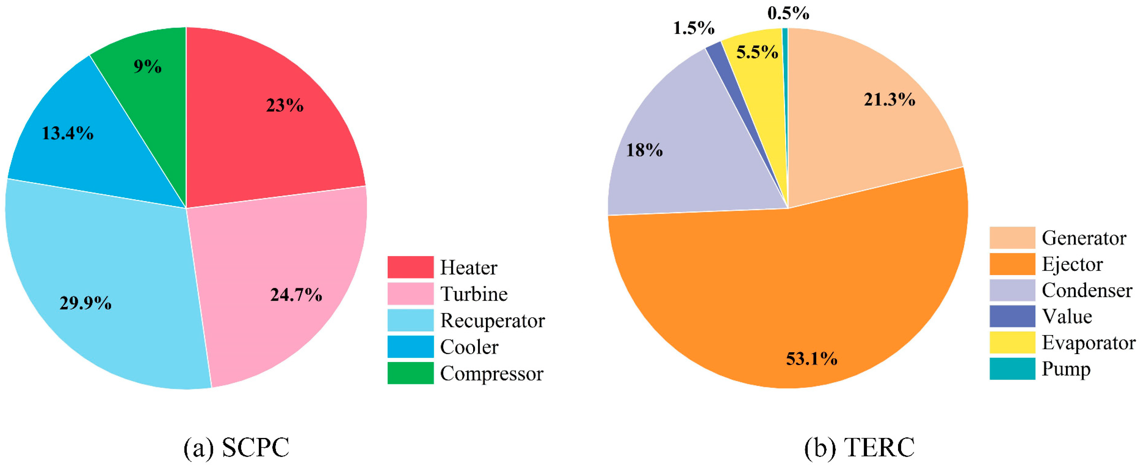
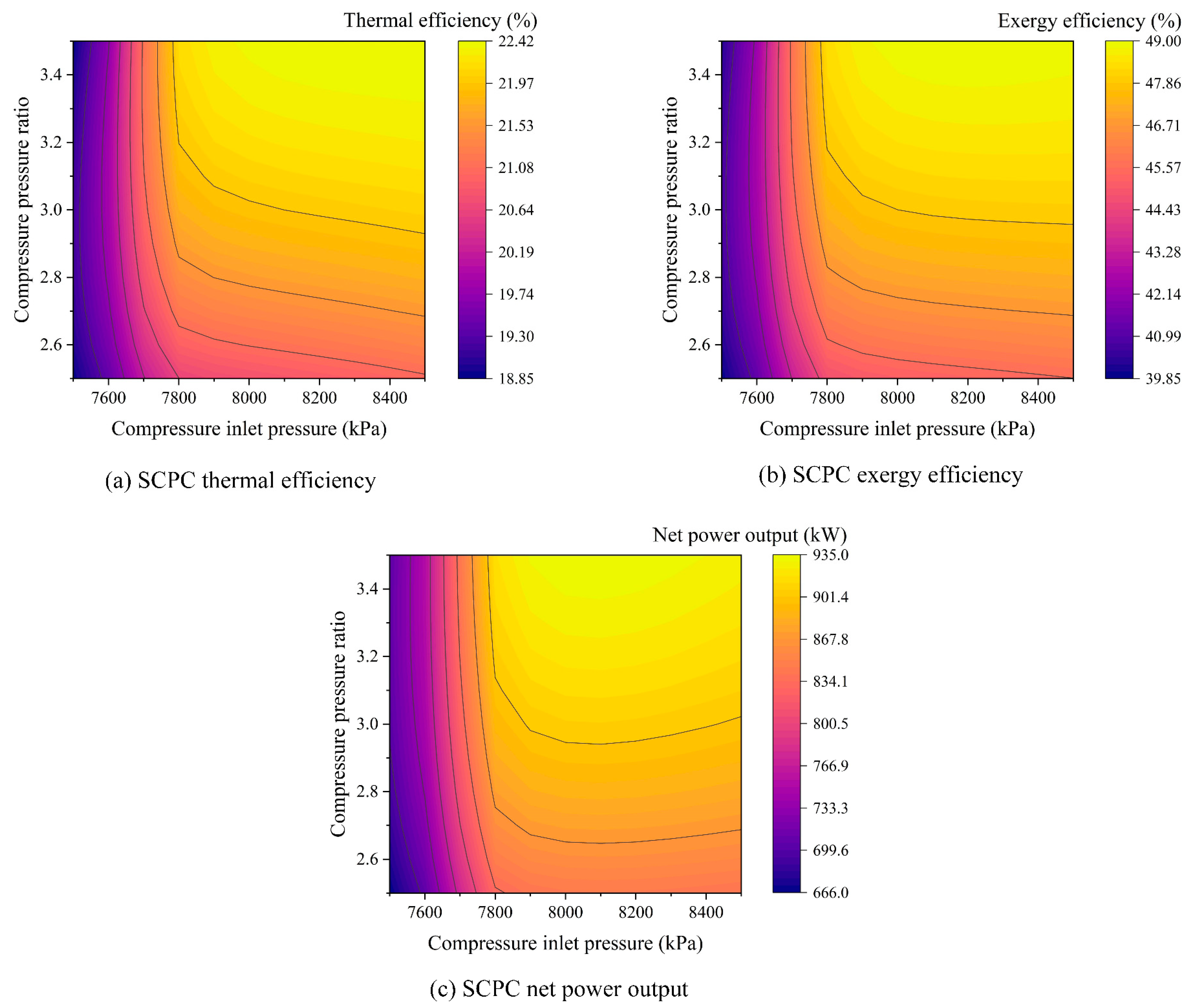
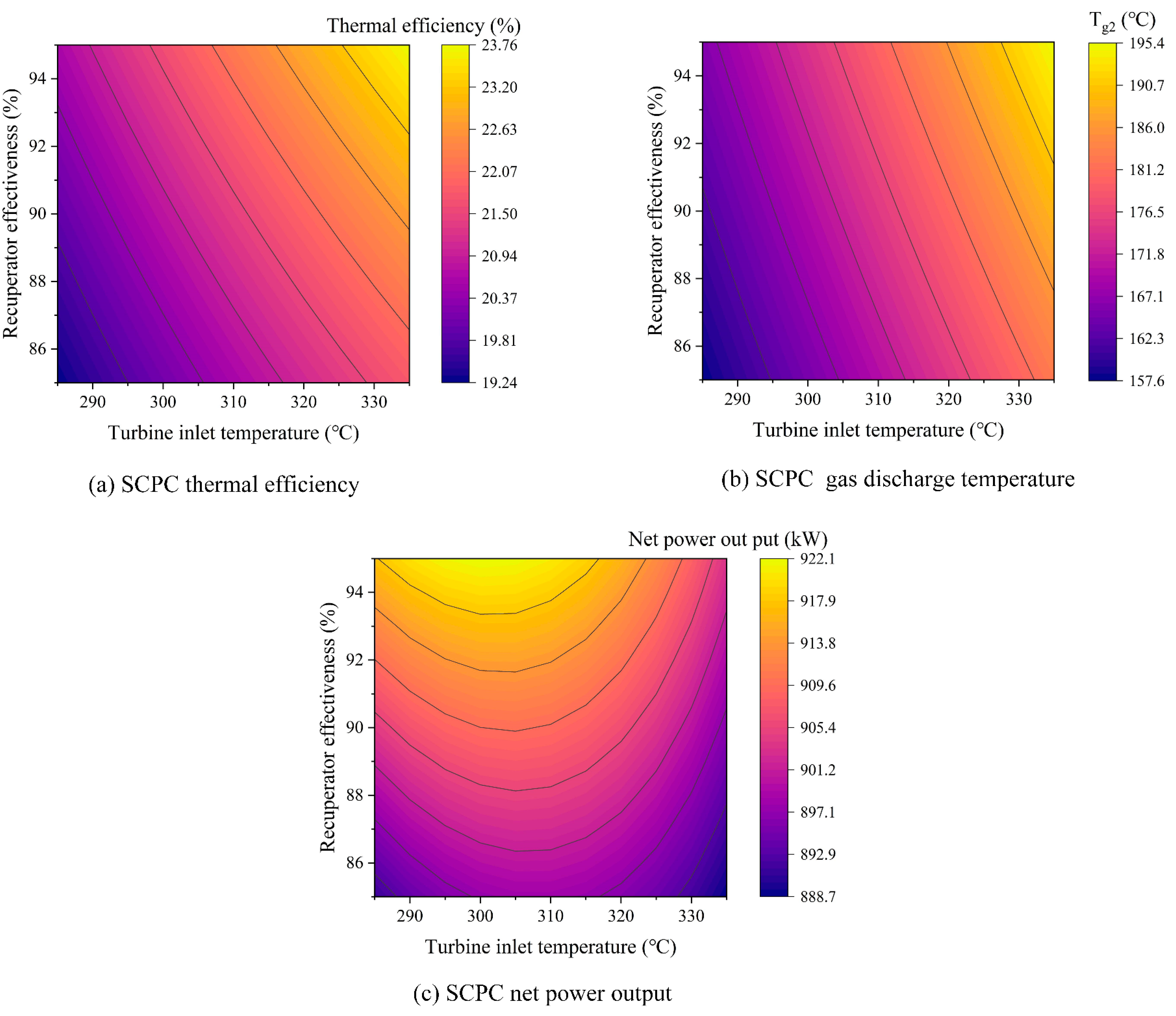
Figure 1. The detailed mathematical model of the proposed WHR system is built with the corresponding evaluation indicators and the optimization strategy. Firstly, the dual fuel engine and WHR combined system is compared with the standalone engine from the viewpoints of the thermodynamic, economic, and environmental aspects. The exergy destruction and exergetic efficiency are analyzed for the two cycles at the component level. Then, a detailed parametric study is performed. Finally, the system is optimized to maximize the overall system performance.

2. System Conceptual Design

2.1. Subsection Marine Dual Fuel Engine

The MAN L35/44DF turbocharged engine manufactured by MAN B&W is selected for marine electrical propulsion. The main parameters of the marine dual fuel engine under 100% load with the LNG as its fuel are shown in Table 1. In fact, the mass flow of the exhaust gas and charge air are not much different. Their heat capacities are all approximately 1.0–1.1 kJ/(kg·K); so, the amount of heat available depends on their temperature interval. All the charge air heat from 196 to 50 °C can be harvested, while the exhaust gas can only be utilized to about 120 °C, due to the limit of the dew point and the consideration of buoyancy to disperse the exhaust gas plume [33].

2.2. Proposed System Description

Considering that the jacket cooling water (about 90 °C) is an ideal heat source for district heating and seawater desalination, the proposed WHR system for the marine dual fuel engine is designed by utilizing the exhaust gas and charged air heat for power augmentation and refrigeration. Figure 2 displays the flowchart of the marine dual fuel engine with the proposed WHR system. The flue gas exhaust heat with a relatively high temperature is directly extracted by a recuperative SCPC since there is no need for an exhaust after-treatment system. Given the relatively low temperature of the charged air heat, which does not pose a risk to the organic working fluids, the TERC is used to convert the air waste heat into cooling capacity. Clearly, the SCPC consists of a gas heater, a recuperator, a turbine (T), a compressor (C), and a gas cooler. In addition, the TERC system comprises a generator, an ejector, a pump, a value, an evaporator, and a condenser.
The operation of these two cycles can be seen with the help of the TS diagram presented in Figure 3. In the SCPC, the compressor first compresses the low-temperature CO2 stream before allowing it to enter the recuperator, where it is heated by the exhaust heat from the turbine outlet. Then, it flows into the heater and continues to be heated by the dual fuel engine exhaust gas. After that, the CO2 steam expands in the turbine to the output power, and the exhaust CO2 releases heat in the recuperator hot side. Finally, the cooling water exchanges heat with it and cools it to near its critical temperature. In the TERC, R245fa (widely used in power cycles for marine engine WHR) with 0 ozone depletion potential is employed as the refrigerant. The working fluid is separated into two streams at the condenser outlet. After the first part is compressed by the pump, it enters the generator to recover the engine charge air waste heat. Then it flows into the ejector as the primary stream. While the second part is depressurized by the throttle valve and then it enters the evaporator to output cooling capacity. The evaporator outlet refrigerant is sucked into the ejector as the secondary flow. These two parts of the stream converge in the ejector and flow into the condenser together.
Several reasonable assumptions are adopted to simplify the calculation of the proposed system: (1) the WHR system reaches a steady state; (2) the pressure drops and the heat loss in the pipes can be overlooked; (3) the adiabatic efficiency of the fluid machinery remains unchanged; and (4) the potential and kinetic energy can be neglected.

3. Modeling and Method

The model of the proposed WHR system is built on the MATLAB platform. In addition, the thermal property parameters of the working fluids are obtained by embedding the REFPROP database.

3.1. Energy and Exergy Model

Based on the conservation of mass and energy as follows, the steady-state model of each component in the WHR system can be obtained, as listed in Table 2.
m ˙ in , k = m ˙ out , k
Q ˙ k + m ˙ in , k h in , k + u in , k 2 2 = W ˙ k + m ˙ out , k h out , k + u out , k 2 2
The effectiveness of the recuperator in the SCPC is defined as follows:
ε r e c = h E h F h E h B , t
The structure of the ejector in the TERC is depicted in Figure 4. Its detailed model is built, as shown in Table A1 of Appendix A, on the premise of the following assumptions: (1) the pressure drop inside the ejector is negligible; (2) the inlet velocities of the primary and secondary flows can be neglected; (3) the mixing process of the two flows is assumed to be isobaric; and (4) the ejector internal energy losses are modeled by the nozzle, mixing, and diffuser efficiency.
To give information about the system’s irreversibility and reveal the exergy rate lost in each component, the exergetic balance equation of each component in the proposed WHR system is built and written in the following form:
E ˙ F , k E ˙ P , k = E ˙ D , k + E ˙ L , k
Due to the chemical exergy of the pure working fluid, the thermodynamic cycle can be ignored, and the exergy rate of each state point can be expressed as follows. The exergy balance equations of each component can be calculated as shown in Table 3.
E ˙ i = m   ˙ h i h 0 T 0   s i s 0

3.2. System Evaluation Indicators

In order to assess and optimize the proposed marine engine and WHR combined system, some evaluation indicators for the SCPC, the TERC, and the combined system are adopted. For the SCPC, its net power output, cycle thermal efficiency, and exergy efficiency are expressed as:
W ˙ net , SCPC = W ˙ tur W ˙ com
η th ,   SCPC = W ˙ sCO 2 / m ˙ gas h g 1 h g 2
η ex ,   SCPC = W ˙ sCO 2 / m ˙ gas e g 1 e g 2
For the TERC, the COP (coefficient of performance) is expressed as:
C O P TERC = Q ˙ eva / Q ˙ gen + W ˙ pum
The COP of the electrically driven refrigeration system (COPequ) is used to treat the TERC cooling capacity in the same order of magnitude as the power generation [34], and then, the contribution of the TERC can be easily compared with the engine and the SCPC. The equivalent power generation is described as:
W ˙ equ , eva = Q ˙ eva / C O P equ
For the engine and WHR combined system, the equivalent total electricity output and the engine’s fuel efficiency can be calculated as:
W ˙ tot , equ = W ˙ engine + W ˙ net , SCPC + W ˙ equ , eva W ˙ pum
η fuel = W ˙ tot , equ / m ˙ fuel LHV
The electrical efficiency and primary energy rate (PER) are employed to reflect the role of the refrigeration system from an intuitive point of view.
η ele = W ˙ engine + W ˙ net , SCPC W ˙ pum / m ˙ fuel L H V
P E R = W ˙ engine + W ˙ net , SCPC + Q ˙ eva W ˙ pum / m ˙ fuel L H V
The specific fuel consumption (SFC) and specific CO2 emission (SCE) are used to evaluate the system from the economic and environmental viewpoints.
S F C = m ˙ fuel / W ˙ tot , equ
S C E = m ˙ co 2 , emi / W ˙ tot , equ

4. System Design and Optimization Method

4.1. System Design Parameters

The system’s design parameters include two parts. Some of these parameters (e.g., the compressor isentropic efficiency) are based on the current technology of the equipment design. In contrast, other parameters are relevant to the proposed system and have to be optimized later, such as the turbine inlet temperature.
The exhaust gas is modeled as a blend, considering the mean value of the main components (i.e., N2, O2, H2O, and CO2), based on the measured composition shown in Table A2 of Appendix A. The mass fraction of the exhaust gas can be obtained: N2 = 73.13%, O2 = 13.86%, H2O = 4.53%, CO2 = 8.48%. Then, the thermal physical parameters of the exhaust gas can be obtained with REFPROP. The COP of the traditional electrically driven shipboard refrigeration system is about 3.9 [35]; thus, a conservative value of it, equal to 4.0, is employed in Equation (10). The values of the other input parameters for the proposed WHR system are presented in Table 4.

4.2. Optimization Strategy

The system performance is sensitive to the system operating parameters; so, it is necessary to optimize them to maximize the system performance. The decision variables considered in the proposed system are the compressor inlet pressure and pressure ratio, the turbine inlet temperature, the recuperator effectiveness, the generating temperature, and the pinch point temperature (PPTD) in the generator.
The equivalent total electricity output is set as the single objective function to optimize the proposed system because it can comprehensively evaluate the system performance and is related to the engine’s fuel efficiency and specific fuel consumption (which is proportional to the carbon dioxide emissions).
The genetic algorithm (GA) is a widely used optimization method in the thermodynamic system; it is based on natural genetics and searches for global optimum solutions [36]. In this work, the GA is adopted to find the maximum value of the equivalent total electricity output of the combined system. Its tuning parameters are listed in Table 5.

5. Results and Discussion

In this section, the system comparison, component exergy analysis, parametric study, and system optimization are performed. The system performance comparison and exergy analysis are based on the design condition. In the parametric study, when the selected parameters are analyzed, the rest remain the same. Finally, the system optimization is based on the reasonable parameter ranges obtained from the parametric study.

5.1. System Performance Comparison

The performance, from the perspective of thermodynamic, economic, and environmental aspects, of the single marine dual fuel engine and the proposed combined system is displayed in Table 6. As can be seen, the total output power of four MAN L35/44DF marine dual fuel engines with a fuel efficiency of 48.58% is 12.72 MW. With the LHV of the LNG being 50,047 kJ/kg, the specific fuel consumption is 148.06 g/kWh. When the proposed WHR system is combined, the temperature of the exhaust gas, utilized by the SCPC, is reduced from 365 to 180.44 °C. On the other hand, the charge air with a temperature of 196 °C is harvested by the TERC, and the temperature is reduced to 51.55 °C, which is close to the required temperature of 50 °C. It demonstrated that the TERC has the potential to recover the charge air heat adequately. After further optimization, the air cooler will not be required, i.e., it will be replaced by the generator of the TERC. By integrating with the proposed WHR system, 886.45 kW power and 1169.79 kW cooling capacity are produced; thus, the electrical efficiency and the PER of the system are increased to 51.97 and 56.77%, respectively.
Integrating with the suggested WHR system results in the production of 886.45 kW of electricity and 1169.79 kW of cooling capacity, raising the system’s electrical efficiency and the PER to 51.97 and 56.77%, respectively. The charge air heat recovery’s contribution to these two efficiencies is what makes them different. Using the COP of the marine electrically driven refrigeration system to equate the cooling capacity to the electric, the equivalent total electricity output is increased from 12,720 to 1389.89 kW. Therefore, the fuel efficiency has increased from 48.58 to 53.09%, with a growth rate of 9.27%. Similarly, the specific fuel consumption is reduced from 148.06 to 135.50 g/kWh, and the corresponding fuel saving is 12.56 g/kWh. The results of the comparison illustrate the superiority of the proposed WHR system for the marine engine.

5.2. System Exergy Analysis

In an attempt to locate and quantify the irreversibility of the thermal processes in the proposed WHR system, the exergy analysis at the component level is carried out, and the results are listed in Table 7. These results are also displayed in Figure 5 to reveal the operating condition of the components more clearly. Clearly, the ejector has the highest irreversible loss rate of 369.41 kW in the overall WHR system, with a relatively low exergy efficiency of 38.67%. In contrast, the pump and the value have the smallest exergy destruction rate; their values are 3.81 and 10.76 kW, respectively. On the other hand, although the exergy efficiencies of both the heater and the pump are relatively high (more than 80%), the heater has about 50 times the exergy destruction rate of the pump. The main reason for this phenomenon is that the work consumed by the pump is much less than the heat load of the heater.
Figure 6 shows the exergy destruction ratio of each component in the SCPC and TERC subsystems. The recuperator has the most significant exergy destruction ratio of 29.9% in the SCPC. In the TERC, the ejector’s exergy destruction ratio, at 53.1%, is the highest among the other components. The reason for the former is that the CO2 power cycle has a sizeable regenerative load, and the temperature difference at the hot end of the recuperator is large due to the mismatch of the heat capacity of the CO2 in the cold and hot path. The latter is due to the primary flow of the ejector having absorbed the charge air waste heat at a higher generating temperature. After entering the ejector, its temperature is reduced to close to the ambient temperature. So, from the viewpoint of exergy, the quality of a large amount of high-grade energy is reduced. Therefore, a more efficient recuperator and ejector can be used to improve the proposed WHR system performance further, if technical and economic conditions permit.

5.3. Parametric Study

The thermodynamic system performance is susceptible to its operating parameters. Thus, it is imperative to analyze the influence of the parameters on the SCPC and the TERC system.

5.3.1. Parametric Study of the SCPC

The compressor process is close to the critical point of carbon dioxide, where the thermophysical properties of the working fluid will change drastically. Thus, the thermodynamic performance of the SCPC is sensitive to the compressor inlet condition. The compressor inlet condition temperature is usually limited by the cooling water temperature; so, the turbine inlet pressure and the compressor pressure ratio are chosen as the independent variables. The variation of the cycle thermal efficiency, the exergy efficiency, the and net power output of the SCPC is studied, and the results are shown in Figure 7.
Referring to Figure 7a, at a specific pressure ratio, as the compressor inlet temperature increases, the thermal efficiency first increases rapidly. The growth trend gradually levels off when the inlet pressure exceeds about 7.8 MPa. The reason is that as the inlet pressure increases, the turbine outlet pressure increases more rapidly; so, the enthalpy differences before and after the turbine and compressor all increase. Additionally, the growth of the enthalpy difference of the turbine is higher than that of the compressor; so, the cycle thermal efficiency gradually increases. When the inlet pressure exceeds 7.8 MPa, the effect of the compressor is more significant; so, the growth trend becomes slower. From the perspective of the fixed turbine inlet pressure, the cycle efficiency increases gradually as the pressure ratio increases. Still, at lower compressor inlet pressure conditions, the cycle efficiency basically remains unchanged. This is because, at this time, the roles of the compressor and turbine are relatively offset.
It can be observed from Figure 7b,c that the SCPC’s net power output and exergetic efficiency all perform a similar changing trend to the thermal efficiency, but when the compressor inlet pressure is around 8.1 MPa, the system output performance is the best. This is primarily a subtle effect of changes in the heat input. However, the heat and thermal exergy input to the system change simultaneously; so, the exergy efficiency follows the same trend as the thermal efficiency, except that the exergy efficiency is more than twice as high as the thermal efficiency.
In the same way, the influence of the turbine inlet temperature and recuperator effectiveness as another two key parameters of the SCPC are analyzed. To more clearly examine the impact of these two parameters on the system power production, which is significant in the evaluation of the combined system performance, the variation of the gas discharge temperature (Tg2) is shown to reflect the variation of the heat input to the power cycle. These results are demonstrated in Figure 8.
Referring to Figure 8a, the thermal efficiency of the power cycle increases steadily with the recuperator effectiveness (RE) and the turbine inlet temperature (T4). On the one hand, as the turbine inlet temperature increases, the enthalpy difference between the turbine inlet and outlet increases. On the other hand, with the increase in RE, the CO2 stream at the compressor outlet is preheated to a higher temperature by the exhaust CO2 of the turbine; so, the enthalpy difference of the CO2 before and after the heater decreases. Referring to Figure 8b, the Tg2 increases with the increase in RE, and this means less heat input to the system. This is due to the pinch point occurring at the cold end of the heater. The increase in RE leads to an increase in the heater inlet CO2 temperature, which in turn leads to an increase in Tg2. In addition, the increase of T4 leads to an increment of Tg2, which is because the temperature of the turbine outlet exhaust CO2 increases.
The combined effect of thermal efficiency and heat input to the system results in a change in the net power generation, as shown in Figure 8c. The power generation of the power cycle gradually increases with the improvement of the effectiveness of the recuperator. On the other hand, with the increment of T4, the output work first increases and then decreases. Accordingly, there is a peak value of T4 of about 305 °C that maximizes the net power output.

5.3.2. Parametric Study of the TERC

Similarly, the parameters of the TERC can also significantly affect its system output performance or, more precisely, the cooling capacity. As the condensation and evaporation temperature are limited by the user-side demand and the external environment, the influence of the generating temperature (Tgen) and the pinch point temperature difference of the generator (PPTDgen) is explored, as presented in Figure 9.
Referring to Figure 9a, the COP of the TERC system does not change with PPTDgen but increases monotonically with Tgen. The reason for this phenomenon is that the COP, as the performance of the cycle itself, does not change with external conditions. The increase in Tgen results in an increase in the temperature of the primary flow of the ejector, which can entrain more secondary flow. The variation of the charge air cooler inlet temperature (Ta3) with the two variables is shown in Figure 9b. When the PPTDgen is greater than 10 °C, as the generating temperature increases, Ta3 increases first and then decreases. It means that the charge air waste heat can be recovered more efficiently at high and low generating temperatures. When the PPTDgen is lower than 10 °C, Ta3 can be reduced to 50 °C at different generating temperature conditions, and the charge air cooler can be entirely replaced by the evaporator. As the pump consumes less power, the change in COP is primarily caused by the combined action of the above two indicators. As shown in Figure 9c, when the Tgen is high, and the PPTDgen is low (yellow area in the figure), the cooling capacity of the TERC reaches the maximum value of 1348.85 kW. The cooling capacity at this condition is much greater than that under the design conditions (1169.79 kW), highlighting the need for optimization work.

5.4. System Optimization

In the parametric study, the influence of the key parameters was analyzed by fixing the remaining parameters as unchanged; in addition, the selected parameter interval cannot be infinitely small. Therefore, the peaks appearing in the figure are at most local optimal solutions. In this section, the GA is utilized to find the globally optimal solution of the operating parameters in the proposed WHR system. The reasonable value of the boundary conditions, as confirmed by the parametric study, is presented in Table 8.
The system optimization results, the optimum value of the decision variables, and the corresponding system performance are listed in Table 9. It should be noted that the optimum values of the compressor pressure ratio, the recuperator effectiveness, and the generating temperature appear on the boundary. At the same time, the other three parameters have optimal solutions within the boundary conditions. Under optimal conditions, the charge air waste heat can be wholly absorbed, and the air cooler can be omitted. The temperature of the exhaust gas is reduced to 179.90 °C, which is just right as the heat source for the shipboard heat recovery steam generator (HRSG). Therefore, an additional 906.74 kW power and 1349.01 kW cooling capacity are produced. From the perspective of the whole system (i.e., the marine dual fuel engine combined with the proposed WHR system), the total equivalent total power output, fuel efficiency, specific fuel consumption, and specific CO2 emission are 13.96 MW, 53.33%, 137.87 g/kWh, and 537.44 g/kWh, respectively.
To intuitively show the practicability of the proposed WHR system and reveal the more precise operation condition obtained by the optimization, Figure 10 displays the performance of the marine engine without the WHR system and the combined system performance in the design and optimum results. As can be seen, compared with the single marine dual fuel engine, the overall performance of the proposed integrated system is improved by 9.27% under the design conditions. After optimization, the system performance improvement rate is 9.78%. Specifically, the engine’s fuel efficiency increased by 4.75 percentage points, which is equivalent to a fuel saving of 13.19 g/kWh and a reduction in CO2 emissions of 52.56 g/kWh.

6. Conclusions

This paper focused on improving the fuel efficiency of a marine dual fuel engine manufactured by MAN B&W by recovering the exhaust gas and the charge air waste heat. A supercritical CO2 Brayton cycle with recuperative layout and a thermally driven ejector refrigeration cycle were employed to harvest the exhaust gas and charge air heat, respectively. The evaluation, from multiple perspectives, and the optimization were conducted to investigate the system performance and prove its feasibility. The main conclusions are summarized below:
(1)
Compared with the single marine dual fuel engine, the performance of the proposed combined system is improved by about 9.27% under the design condition. At this time, the temperature of the charge air is reduced to approximately 52 °C, and an air cooler with a small cooling load is still required.
(2)
The results of the system exergy analysis demonstrate that the pump and the throttle value have the lowest exergy destruction rate in the combined system. The ejector and the recuperator contribute to the highest share of exergy destruction, accounting for around 53% and 30% of their respective cycles.
(3)
A detailed parametric study was carried out to explore the influence of the operating parameters on the system performance. The results indicate that there are optimal values for the inlet pressure of the compressor and the inlet temperature of the turbine.
(4)
With the total equivalent power as the objective function, the system optimization was conducted. The results confirmed that the fuel efficiency, specific fuel consumption, and CO2 emissions of the combined system were approximately 53.3%, 137.9 g/kWh, and 537.4 g/kWh, respectively, which have better economic and environmental benefits. Meanwhile, the charge air cooler can be completely replaced by the generator of the ejector refrigeration cycle.

Author Contributions

Conceptualization, Y.J. (Yuemao Jiang) and Z.W.; methodology, Z.W.; software, Y.J. (Yuemao Jiang); validation, Y.M.; investigation, Y.M.; resources, Y.J. (Yulong Ji); writing—original draft preparation, Y.J. (Yuemao Jiang) and Z.W.; writing—review and editing, W.C. and F.H.; visualization, Z.W.; supervision, Z.W. and F.H.; project administration, Y.J. (Yulong Ji); funding acquisition, Y.J. (Yulong Ji). All authors have read and agreed to the published version of the manuscript.

Funding

This work was funded by the National Natural Science Foundation of China (51906026), Dalian High-level Talents Innovation Support Program (2021RQ132), the Fundamental Research Funds for the Central Universities (3132022224, 3132022350), the China Postdoctoral Science Foundation (2020M680928), the Natural Science Foundation of Liaoning Province (2020-BS-067), and the National Key Research and Development Program of China (2019YFE0116400) and 111 Project (B18009).

Data Availability Statement

Not applicable.

Conflicts of Interest

The authors declare no conflict of interest.

Appendix A

Table A1. One-dimensional ejector model based on energy and momentum conservation.
SectionParameterFormula
Suction chamberEntrainment ratio μ = m ˙ s f m ˙ p f = η n η m η d h p f , n i h p f , n e , s h m f , d , s h m f , m 1
Isentropic efficiency of nozzle η n = h p f , i h p f , o h p f , i h p f , o , s
Velocity of primary flow v p f , o = 2 η n h p f , i h p f , o , s
Mixing sectionMixing efficiency η m f = v m f 2 v m f , s 2
Velocity of mixed flow v m f = v p f , o 1 + μ η m f
Enthalpy of mixed flow h m f = h p f , i + μ h s f , i 1 + μ v m f 2 2
DiffuserDiffuser efficiency η d f = h d f , s h m f h d f h m f
Enthalpy of flow at the diffuser exit h d f = h m f + v m f 2 2
Quality of vapor at the ejector exit x d f = 1 1 + μ
Table A2. Composition of the dual fuel engine exhaust gas.
CompositionContent (g/kWh)Assumption (g/kWh)Mass Fraction (%)
N25020–5160509073.13
O2900–103096513.86
H2O260–3703154.53
CO2560–6205908.48
SOX0.070-
NOX0.07–0.150-
HC0.04–0.10-
CO0.006–0.00110-
Inert gases0.90-

References

  1. Alfani, D.; Binotti, M.; Macchi, E.; Silva, P.; Astolfi, M. sCO2 power plants for waste heat recovery: Design optimization and part-load operation strategies. Appl. Therm. Eng. 2021, 195, 117013. [Google Scholar] [CrossRef]
  2. Poulsen, R.T.; Johnson, H. The logic of business vs. the logic of energy management practice: Understanding the choices and effects of energy consumption monitoring systems in shipping companies. J. Clean. Prod. 2016, 112, 3785–3797. [Google Scholar] [CrossRef] [Green Version]
  3. Senary, K.; Tawfik, A.; Hegazy, E.; Ali, A. Development of a waste heat recovery system onboard LNG carrier to meet IMO regulations. Alex. Eng. J. 2016, 55, 1951–1960. [Google Scholar] [CrossRef] [Green Version]
  4. Ren, H.; Ding, Y.; Sui, C. Influence of EEDI (Energy Efficiency Design Index) on Ship–Engine–Propeller Matching. J. Mar. Sci. Eng. 2019, 7, 425. [Google Scholar] [CrossRef] [Green Version]
  5. Mondejar, M.E.; Andreasen, J.G.; Pierobon, L.; Larsen, U.; Thern, M.; Haglind, F. A review of the use of organic Rankine cycle power systems for maritime applications. Renew. Sustain. Energy Rev. 2018, 91, 126–151. [Google Scholar] [CrossRef]
  6. Verhelst, S.; Turner, J.W.G.; Sileghem, L.; Vancoillie, J. Methanol as a fuel for internal combustion engines. Prog. Energy Combust. Sci. 2019, 70, 43–88. [Google Scholar] [CrossRef] [Green Version]
  7. Beatrice, C.; Denbratt, I.; Di Blasio, G.; Di Luca, G.; Ianniello, R.; Saccullo, M. Experimental Assessment on Exploiting Low Carbon Ethanol Fuel in a Light-Duty Dual-Fuel Compression Ignition Engine. Appl. Sci. 2020, 10, 7182. [Google Scholar] [CrossRef]
  8. Deniz, C.; Zincir, B. Environmental and economical assessment of alternative marine fuels. J. Clean. Prod. 2016, 113, 438–449. [Google Scholar] [CrossRef]
  9. Han, F.; Wang, Z.; Ji, Y.; Li, W.; Sundén, B. Energy analysis and multi-objective optimization of waste heat and cold energy recovery process in LNG-fueled vessels based on a triple organic Rankine cycle. Energy Convers. Manag. 2019, 195, 561–572. [Google Scholar] [CrossRef]
  10. Schinas, O.; Butler, M. Feasibility and commercial considerations of LNG-fueled ships. Ocean Eng. 2016, 122, 84–96. [Google Scholar] [CrossRef]
  11. Balcombe, P.; Brierley, J.; Lewis, C.; Skatvedt, L.; Speirs, J.; Hawkes, A.; Staffell, I. How to decarbonise international shipping: Options for fuels, technologies and policies. Energy Convers. Manag. 2019, 182, 72–88. [Google Scholar] [CrossRef]
  12. Zhu, S.; Zhang, K.; Deng, K. A review of waste heat recovery from the marine engine with highly efficient bottoming power cycles. Renew. Sustain. Energy Rev. 2020, 120, 109611. [Google Scholar] [CrossRef]
  13. Olaniyi, E.O.; Prause, G. Investment Analysis of Waste Heat Recovery System Installations on Ships’ Engines. J. Mar. Sci. Eng. 2020, 8, 811. [Google Scholar] [CrossRef]
  14. Lion, S.; Vlaskos, I.; Taccani, R. A review of emissions reduction technologies for low and medium speed marine Diesel engines and their potential for waste heat recovery. Energy Convers. Manag. 2020, 207, 112553. [Google Scholar] [CrossRef]
  15. Wang, Z.; Jiang, Y.; Han, F.; Yu, S.; Li, W.; Ji, Y.; Cai, W. A thermodynamic configuration method of combined supercritical CO2 power system for marine engine waste heat recovery based on recuperative effects. Appl. Therm. Eng. 2022, 200, 117645. [Google Scholar] [CrossRef]
  16. Uusitalo, A.; Nerg, J.; Grönman, A.; Nikkanen, S.; Elg, M. Numerical analysis on utilizing excess steam for electricity production in cruise ships. J. Clean. Prod. 2019, 209, 424–438. [Google Scholar] [CrossRef]
  17. Liang, Y.; Shu, G.; Tian, H.; Liang, X.; Wei, H.; Liu, L. Analysis of an electricity–cooling cogeneration system based on RC–ARS combined cycle aboard ship. Energy Convers. Manag. 2013, 76, 1053–1060. [Google Scholar] [CrossRef]
  18. Liu, X.; Nguyen, M.Q.; Chu, J.; Lan, T.; He, M. A novel waste heat recovery system combing steam Rankine cycle and organic Rankine cycle for marine engine. J. Clean. Prod. 2020, 265, 121502. [Google Scholar] [CrossRef]
  19. Song, J.; Song, Y.; Gu, C.-w. Thermodynamic analysis and performance optimization of an Organic Rankine Cycle (ORC) waste heat recovery system for marine diesel engines. Energy 2015, 82, 976–985. [Google Scholar] [CrossRef]
  20. Zhu, Y.; Li, W.; Sun, G.; Li, H. Thermo-economic analysis based on objective functions of an organic Rankine cycle for waste heat recovery from marine diesel engine. Energy 2018, 158, 343–356. [Google Scholar] [CrossRef]
  21. Sung, T.; Kim, K.C. Thermodynamic analysis of a novel dual-loop organic Rankine cycle for engine waste heat and LNG cold. Appl. Therm. Eng. 2016, 100, 1031–1041. [Google Scholar] [CrossRef]
  22. Civgin, M.G.; Deniz, C. Analyzing the dual-loop organic rankine cycle for waste heat recovery of container vessel. Appl. Therm. Eng. 2021, 199, 117512. [Google Scholar] [CrossRef]
  23. Song, J.; Li, X.-s.; Ren, X.-d.; Gu, C.-w. Performance improvement of a preheating supercritical CO2 (S-CO2) cycle based system for engine waste heat recovery. Energy Convers. Manag. 2018, 161, 225–233. [Google Scholar] [CrossRef]
  24. Wang, Z.; Jiang, Y.; Ma, Y.; Han, F.; Ji, Y.; Cai, W. A partial heating supercritical CO2 nested transcritical CO2 cascade power cycle for marine engine waste heat recovery: Thermodynamic, economic, and footprint analysis. Energy 2022, 261, 125269. [Google Scholar] [CrossRef]
  25. Zhang, R.; Su, W.; Lin, X.; Zhou, N.; Zhao, L. Thermodynamic analysis and parametric optimization of a novel S–CO2 power cycle for the waste heat recovery of internal combustion engines. Energy 2020, 209, 118484. [Google Scholar] [CrossRef]
  26. Li, L.; Tian, H.; Shi, L.; Wang, J.; Li, M.; Shu, G. Adaptive flow assignment for CO2 transcritical power cycle (CTPC): An engine operational profile-based off-design study. Energy 2021, 225, 120262. [Google Scholar] [CrossRef]
  27. Pan, P.; Yuan, C.; Sun, Y.; Yan, X.; Lu, M.; Bucknall, R. Thermo-economic analysis and multi-objective optimization of S-CO2 Brayton cycle waste heat recovery system for an ocean-going 9000 TEU container ship. Energy Convers. Manag. 2020, 221, 113077. [Google Scholar] [CrossRef]
  28. Wu, C.; Wang, S.-S.; Bai, K.-L.; Li, J. Thermodynamic analysis and parametric optimization of CDTPC-ARC based on cascade use of waste heat of heavy-duty internal combustion engines (ICEs). Appl. Therm. Eng. 2016, 106, 661–673. [Google Scholar] [CrossRef]
  29. Xia, J.; Wang, J.; Lou, J.; Zhao, P.; Dai, Y. Thermo-economic analysis and optimization of a combined cooling and power (CCP) system for engine waste heat recovery. Energy Convers. Manag. 2016, 128, 303–316. [Google Scholar] [CrossRef]
  30. Huang, W.; Wang, J.; Xia, J.; Zhao, P.; Dai, Y. Performance analysis and optimization of a combined cooling and power system using low boiling point working fluid driven by engine waste heat. Energy Convers. Manag. 2019, 180, 962–976. [Google Scholar] [CrossRef]
  31. Wu, C.; Xu, X.; Li, Q.; Li, J.; Wang, S.; Liu, C. Proposal and assessment of a combined cooling and power system based on the regenerative supercritical carbon dioxide Brayton cycle integrated with an absorption refrigeration cycle for engine waste heat recovery. Energy Convers. Manag. 2020, 207, 112527. [Google Scholar] [CrossRef]
  32. Wang, Z.; Mo, X.; Qin, P.; Zhao, Z.; Ouyang, T. Multi-dimensional assessment and multi-objective optimization of electricity-cooling cogeneration system driven by marine diesel engine waste heat. J. Clean. Prod. 2022, 334, 130187. [Google Scholar] [CrossRef]
  33. Weiland, N.; Thimsen, D. A practical look at assumptions and constraints for steady state modeling of sCO2 Brayton power cycles. In Proceedings of the 5th International Symposium–Supercritical CO2 Power Cycles, San Antonio, TX, USA, 28–31 March 2016. [Google Scholar]
  34. Shu, G.; Wang, X.; Tian, H.; Liang, Y.; Liu, Y.; Liu, P. Analysis of an electricity-cooling cogeneration system for waste heat recovery of gaseous fuel engines. Sci. China Technol. Sci. 2015, 58, 37–46. [Google Scholar] [CrossRef]
  35. Cao, T.; Lee, H.; Hwang, Y.; Radermacher, R.; Chun, H.-H. Performance investigation of engine waste heat powered absorption cycle cooling system for shipboard applications. Appl. Therm. Eng. 2015, 90, 820–830. [Google Scholar] [CrossRef]
  36. Ouyang, T.; Su, Z.; Huang, G.; Zhao, Z.; Wang, Z.; Chen, N.; Huang, H. Modeling and optimization of a combined cooling, cascaded power and flue gas purification system in marine diesel engines. Energy Convers. Manag. 2019, 200, 112102. [Google Scholar] [CrossRef]
Figure 1. Heat balance diagram of the marine engine with the motivation and purpose of this work.
Jmse 10 01404 g001
Figure 2. This schematic diagram of the proposed WHR system for marine dual fuel engine.
Jmse 10 01404 g002
Figure 3. The temperature–entropy figure of the two thermally driven cycles.
Jmse 10 01404 g003
Figure 4. The structure and internal pressure change of the ejector in TERC.
Jmse 10 01404 g004
Figure 5. The influences of compressor inlet pressure and pressure ratio on the performance of the SCPC.
Jmse 10 01404 g005
Figure 6. The exergy destruction ratio of components in the two cycles: (a) SCPC; (b) TERC.
Jmse 10 01404 g006
Figure 7. The influences of compressor inlet pressure and pressure ratio on the performance of the SCPC: (a) thermal efficiency; (b) exergy efficiency; (c) net power output.
Jmse 10 01404 g007
Figure 8. The effect of recuperator effectiveness and turbine inlet temperature on the performance of the SCPC: (a) thermal efficiency; (b) gas discharge temperature; (c) net power output.
Jmse 10 01404 g008
Figure 9. The influences of generating temperature and PPTD of the generator on the performance of the TERC: (a) COP; (b) outlet air temperature; (c) cooling capacity.
Jmse 10 01404 g009
Figure 10. Genetic algorithm for optimizing the engine with WHR system.
Jmse 10 01404 g010
Table 1. The selected marine dual fuel engine’s main parameters of its gas fuel mode.
ParameterUnitValue
Cylinder/6 L
Rotation speedRpm750
Engine outputkW3180
Specific fuel consumptionkJ/kWh7410
Engine efficiency%48.58
Exhaust gas temperature°C365
Exhaust gas mass flowkg/kWh5.79
Charge air temperature°C196
Air cooler outlet temperature°C50
Charge air pressure Bar3.86
Charge air mass flowkg/kWh5.63
Table 2. Energy models of each component in the proposed WHR system.
CycleComponentEnergy Balance Equation
Heater Q ˙ hea = m ˙ gas h g 1 h g 2 = m ˙ CO 2 h 4 h 3
Turbine W ˙ tur = m ˙ CO 2 h 4 h 5 = m ˙ CO 2 h 4 h 5 s η tur
SCPCRecuperator Q ˙ rec = m ˙ CO 2 h 5 h 6 = m ˙ CO 2 h 3 h 2
Cooler Q ˙ coo = m ˙ CO 2 h 6 h 1 = m ˙ cw h 8 h 7
Compressor W ˙ com = m ˙ CO 2 h 2 h 1 = m ˙ CO 2 h 2 s h 1 / η com
Generator Q ˙ gen = m ˙ air h a 1 h a 3 = m ˙ pf h 13 h 10
Ejector m ˙ pf h 13 + m ˙ sf h 29 = m ˙ pf + m ˙ sf h 16
TERCCondenser Q ˙ con = m ˙ pf + m ˙ sf h 16 h 9
Value h 9 = h 19
Evaporator Q ˙ eva = m ˙ sf h 19 h 18
Pump W ˙ pum = m ˙ pf h 10 h 9 = m ˙ pf h 10 s h 9 / η pum
Table 3. Exergetic balance equations of each component in the proposed WHR system.
CycleComponentExergy DestructionExergy Efficiency
Heater E ˙ g 1 E ˙ g 2 E ˙ 4 E ˙ 3 E ˙ 4 E ˙ 3 / ( E ˙ g 1 E ˙ g 2 )
Turbine E ˙ 4 E ˙ 5 W ˙ tur W ˙ tur / E ˙ 4 E ˙ 5
SCPCRecuperator E ˙ 5 E ˙ 6 E ˙ 3 E ˙ 2 E ˙ 3 E ˙ 2 / E ˙ 5 E ˙ 6
Cooler E ˙ 6 E ˙ 1 E ˙ 8 E ˙ 7 E ˙ 8 E ˙ 7 / E ˙ 6 E ˙ 1
Compressor W ˙ com ( E ˙ 2 E ˙ 1 ) E ˙ 2 E ˙ 1 / W ˙ com
Generator E ˙ a 1 E ˙ a 3 E ˙ 13 E ˙ 10 E ˙ 13 E ˙ 10 / E ˙ a 1 E ˙ a 3
Ejector E ˙ 13 + E ˙ 19 E ˙ 16 E ˙ 16 / E ˙ 13 + E ˙ 19
TERCCondenser E ˙ 16 E ˙ 9 E ˙ 21 E ˙ 21 / E ˙ 16 E ˙ 9
Value E ˙ 9 e E ˙ 18 E ˙ 18 / E ˙ 9 e
Evaporator E ˙ 18 E ˙ 19 E ˙ 23 E ˙ 23 /( E ˙ 18 E ˙ 19 )
Pump W ˙ pum E ˙ 10 E ˙ 9 g E ˙ 10 E ˙ 9 g / W ˙ pum
Table 4. Design parameters of the proposed WHR system [33].
ParameterUnitValue
Environment temperature °C20
Turbine inlet temperature°C320
Compressor inlet temperature°C33
Compressor inlet pressurekPa8000
Compressor outlet pressurekPa24,000
Recuperator effectiveness%90
Turbine efficiency%80
Compressor efficiency%82
Pump efficiency %80
Generation temperature°C120
Evaporating temperature°C5
Condensing temperature°C30
PPTD in gas heater°C30
PPTD in generator°C10
ΔP on the heater cold pathkPa200
ΔP on the recuperator cold pathkPa140
ΔP on the recuperator hot pathkPa280
ΔP on the cooler hot pathkPa15
Table 5. Tuning parameters of genetic algorithm.
ParameterPopulationCrossover FractionMigration FractionGenerations Size
Value2000.350.15100
Table 6. System performance comparison of the engine and the proposed combined system.
ItemsSingle EngineEngine with WHR System
Gas discharge temperature (°C)365180.44
Air cooler inlet temperature (°C)19651.55
Power output (kW)12,72013,606.45
Cooling capacity (kW)01169.79
Electrical efficiency (%)48.5851.97
Primary energy rate (%)48.5856.44
Fuel efficiency (%)48.5853.09
Specific fuel consumption (g/kWh)148.06135.50
Specific CO2 emission (g/kWh)590539.96
Table 7. Exergetic analysis of the proposed WHR system.
CycleComponentExergy Destruction (kW)Exergy Efficiency (%)
Heater195.0389.70
Turbine209.4486.95
SCPCRecuperator253.2472.89
Cooler113.6155.23
Compressor75.9384.46
Generator148.1080.01
Ejector369.4138.67
TERCCondenser125.2524.28
Value10.7656.43
Evaporator38.4739.02
Pump3.8180.71
Table 8. Boundary condition of decision variables in the optimization.
ItemsLower BoundaryUpper Boundary
Turbine inlet temperature (°C)280330
Recuperator effectiveness (%)8595
Compressor inlet pressure (kPa)75008500
Compressor pressure ratio2.53.5
Generation temperature (°C)80150
PPTD of generator (°C)525
Table 9. Optimization results and the corresponding system performance.
ItemItemValue
Turbine inlet temperature (°C)314.03
Recuperator effectiveness (%)94.99
Decision variablesCompressor inlet pressure (kPa)8086.67
Compressor pressure ratio 3.49
Generation temperature (°C)149.99
PPTD of generator (°C)6.27
Gas discharge temperature (°C)179.90
Air cooler inlet temperature (°C)50
Power output (kW)13,626.74
Cooling capacity (kW)1349.01
Performance indicatorsElectrical efficiency (%)52.05
Primary energy rate (%)57.20
Fuel efficiency (%)53.33
Specific fuel consumption (g/kWh)134.87
Specific CO2 emission (g/kWh)537.44
Publisher’s Note: MDPI stays neutral with regard to jurisdictional claims in published maps and institutional affiliations.

