1. Introduction
Communication devices and systems on a ship are organized according to the Global Maritime Distress and Safety System (GMDSS), which includes various communication devices for a common purpose. Each of these devices and systems has a dedicated infrastructure, meaning each system has its antenna, control module, peripheral devices, user modules and alike. All devices or systems are networked or interconnected, making the GMDSS system defined on the level of protocols, safety procedures, and communication technology used.
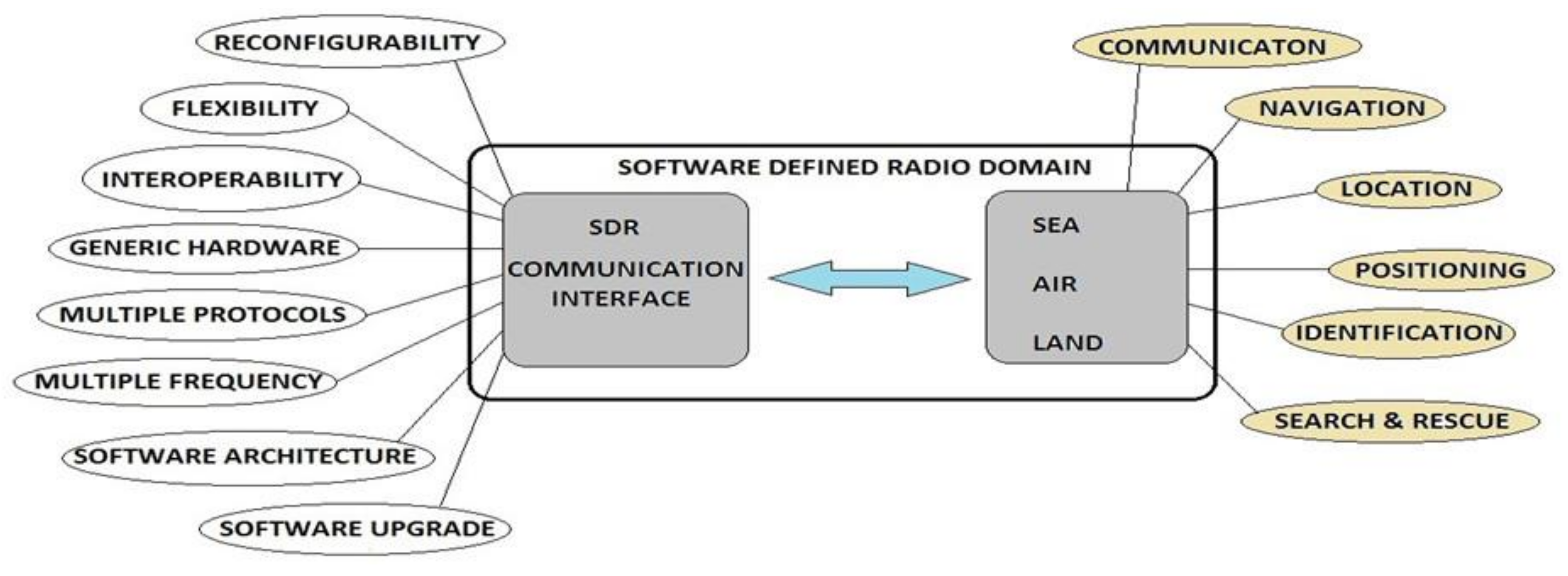
A software-defined radio (SDR) can be defined as a system consisting of an antenna set, generic hardware and a software platform. Even though SDR is currently used mainly as a receiver with a wide range of frequencies (other than in military communications, where very flexible devices for two-way communication already exist), its potential is much greater. To understand what advantages SDR can bring, it is necessary to preview existing communication devices and systems on ships. Let us look at GMDSS and other communication devices on the vessel through a prism of a software-defined radio. We can see that there is room for improvement and for simplifying ship communication systems.
2. Typical Configuration of Ship Communication Systems and Devices
When we talk of maritime communications in the context of large ships (ships more significant than 300 BT), we can divide them into internal communication and external communication. The first category includes communication performed onboard the vessel itself or between some ship sections (bridge, engine room, and cargo spaces) or crew members. The other class, more attractive to us, is the communication towards other vessels in the area, port authorities, ship owners, maritime institutions on land, services, and the like. Even though it does not seem so crucial at first glance, internal communication is the backbone of everyday ship routines.
The Global Maritime Distress and Safety System (GMDSS) was introduced to ships more significant than 300 BT [
1,
2] to cover all communication needs and ensure high availability and reliability of communication. The International Maritime Organization IMO and ITU defined the standards for the GMDSS equipment and procedures for managing marine equipment, the subjects in communication and training methods for the crew members to use GMDSS equipment safely.
The Radio Regulations approve the frequencies used in the GMDSS of the International Telecommunication Union (ITU); see
Table 1.
According to the above-mentioned IMO definition of hardware or the technical part of GMDSS, the system on the ship consists of two self-standing VHF (very high frequency) radio stations, MF/HF (medium frequency/high frequency) radio stations with a telex function, Inmarsat C terminal, NAVTEX (navigational telex) receiver, SART (search and rescue transponder), EPIRB (emergency position-indicating radio beacon) transponder, SSAS (ship security alert system) and LRIT (long-range identification and tracking) system. Other communication equipment on the ship that has been introduced in the last couple of years and is increasingly used is Inmarsat Fleet satellite terminal, VSAT (very small aperture terminal) satellite system and Iridium satellite communication system, as well as GSM for non-formal communication.
The latter equipment mentioned is not a standard part of the GMDSS, and for that reason, it is not subject to strict communication demands such as standard GMDSS equipment. To complement that picture, we add to that devices such as radars, GNSS (global navigation satellite system), AIS (automatic identification system), weather facsimile, and similar devices. In that case, we can see that the ship’s complete communication and navigation equipment is based on the principle of radio wave transmission.
Communication with the exterior surroundings of the ship or with external subjects is conducted through RF transmission in the form of two-way communications, data packages, facsimile, and other communication protocols with which the vessels receive various notifications and messages. We place meteorological reports, information to sailors, EGC (enhanced group call) messages, MSI (maritime safety information) messages, email services, and other non-initiated communications in the latter communication category.
Figure 1 shows the GMDSS equipment communication possibilities with its counterparts onshore and on other ships. As most of these devices require a separate antenna set, the ships’ antenna arrangement represents a particular challenge. On large cargo ships, this challenge is not such a big problem because of waste space; however, if ships are smaller in size or specialized in construction and often have equipment that does not leave much room for antennas, this challenge becomes a problem. Other than requests that specific antennas must be distanced from each other and potential sources of disturbance, there is also a significant problem in obstructions in the form of cranes, masts, ship equipment, etc.
Table 2 shows typical ship communication devices and their frequency band. It is also evident that the communication distance is different for certain types of devices even though the actual distance of terrestrial systems depends on a few factors, such as the height of the antenna, meteorological conditions, and device type.
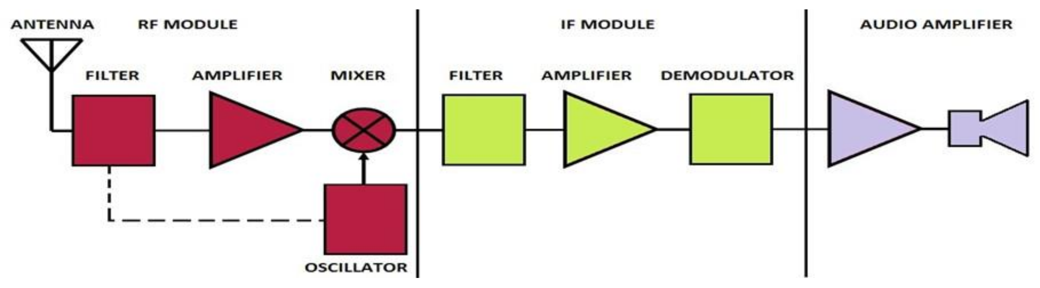
The configuration of the typical radio receiver can be seen in
Figure 2. The classic structure includes the hardware elements of all transceiver components (filters, amplifiers, modulators, oscillators, and mixers), which means that each of the hardware units consists of a dedicated electronic circuitry that performs a specific function. This implies that each device using a specific frequency band for particular applications needs to have components designed specifically for this purpose. Since these are physical components that have specific, limited possibilities and parameters defined by their design, it is clear that the conventional transceiver has its limitations in terms of the frequency spectrum. Therefore, we can conclude that the conventional transceiver based on electronic circuitry designed for a specific purpose is very hard to change. Thus, it is less flexible because it can exchange information only with a similar transceiver within the same frequency band.
3. Basics and Origins of Software-Defined Radio
To overcome the barriers that occur when various equipment within the frequency range is used, an approach has been proposed to develop a system that is so flexible that it can combine all communication technologies into a mutual system. The idea of a radio whose functions would be implemented through a software solution comes from the military. Even though it was a very ambitious plan, it was quickly apparent that many technical problems could not be resolved to achieve the desired goal. However, despite all issues that arose during the development of software-defined radio (SDR), the main components that make SDR in the context of this paper are defined.
3.1. A short Preview of the SDR Development
As a software-defined radio can include a broad range of different applications and approaches, we can use the SDR definition from the International Telecommunication Union (ITU). According to ITU [
3], a software-defined radio (SDR) is a radio transmitter and/or receiver employing a technology that allows the radio frequency (RF) operating parameters including, but not limited to, frequency range, modulation type, or output power to be set or altered by software, excluding changes to operating parameters that occur during the regular pre-installed and predetermined operation of radio according to a system specification or standard.
The origins of a software radio can be traced back to the 1970s, when, as a need of the US military forces, an approach to digital signal processing was made in an attempt to apply software solutions in some of the steps in signal processing. The term software-defined radio (SDR) is also not new either. It appeared in 1995 during the attempt to develop communication platforms intended for the US military forces (project
SpeakEasy I,
SpeakEasy II). Since each branch of the armed forces had its own specifications and requests regarding communication systems, the communication technology was adapted to specific recommendations of the navy, air force, or army. The basic idea of the new communication system was to integrate or to enable the integration of numerous (technologically different) communication systems used in all branches of the military in one standard system called JTRS (joint tactical radio system) [
4]. It is essential to mention that such attempts were quickly accepted in wider research circles, especially among amateur radio enthusiasts. Even though they did not wholly succeed in their attempt, the development continued, and specific progress was achieved.
When defining the goals that implementing a software-defined radio was to achieve, there were attempts to achieve flexibility in integrating newer and older generations of communication systems (
Figure 3). The software architecture of a communication system allows the implementation of newly developed functions and possibilities inside the existing system as well as adjustment to various platforms [
5]. Suppose we can adopt a specific communication system to a newer generation of communication systems with a simple software upgrade. In that case, we can avoid the problem of systems becoming obsolete and significantly increase their life span.
A significant advantage of SDR will be the possibility of remote diagnostics when maintaining such communication systems with software upgrades. Testing and replacing components of the conventional malfunctioning device on the ship is sometimes not possible because of the need for measuring and testing equipment and instruments that are not available onboard. Instead of the current maintenance practice in which the device is taken apart and its components are replaced, SDR would offer the possibility of simple software upgrades. Faster, more straightforward, and more practical access to error correction and fault finding within the system would be achieved with this approach.
3.2. Hardware Environment of SDR
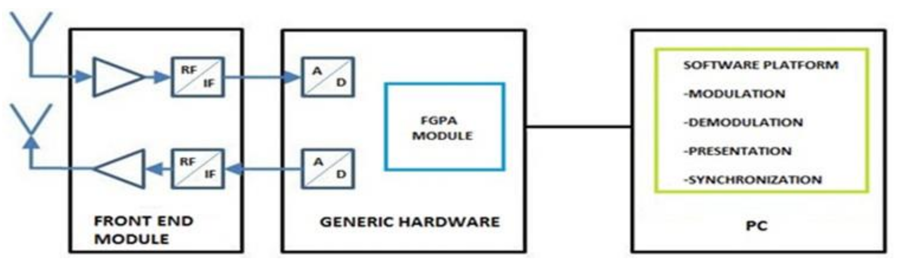
Suppose we are guided by goals that would be achieved by implementing the software-defined radio that applies generic hardware (
Figure 4). In that case, it is logical to define the minimum hardware components in the following manner [
6,
7,
8,
9,
10,
11]:
Transceiver module—The SDR component that presents an antenna platform for connecting two antennas using MIMO (multiple-input, multiple-output) or MISO (multiple-input, single-output) approaches. Due to the frequency range that is to be acquired, it is desired that the module supports all types of antennas used in maritime communication.
Generic hardware—Designed with the help of the FPGA (field-programmable gate array) module with the tendency to transfer to generic general-purpose processors, which gives the system flexibility. Used as preparation for software processing of the signal.
Computer with SDR software-HMI—Includes a computer equipped with a sound card of satisfactory performance. It executes functions by generating waveforms, signal modulation and demodulation, digital signal processing, encryption, and various protocols support. The goal of software processing signals is to cover as many signal processing steps as possible and to transfer processing to the software domain.
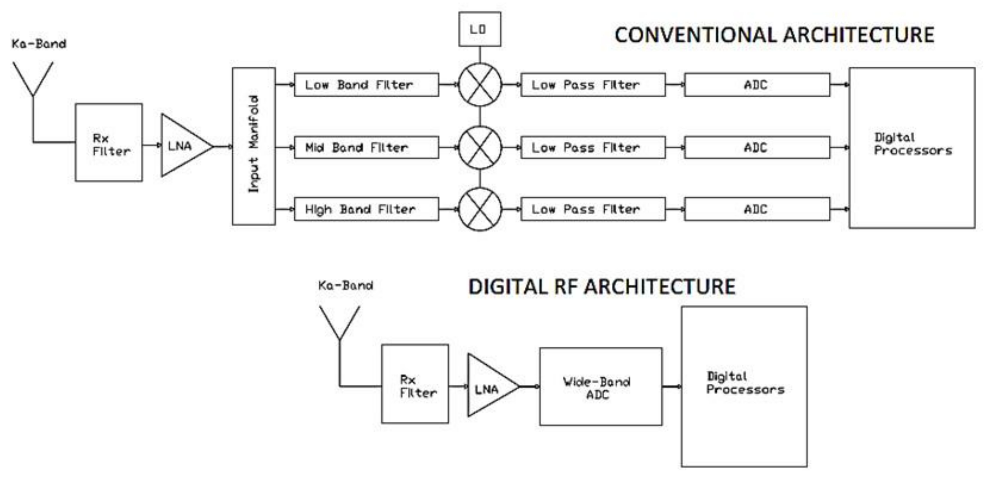
Since a software-defined radio includes a broad spectrum of applicable communication technologies, it is still necessary to define the hardware components that will provide the structure for signal digitization. The primary goal of SDR hardware development is to apply direct digitization to analogue signals. Each analogue input signal is processed within a separate digital processing chain, based on superconductive ADCs, avoiding downconversion of the analogue signal [
12]. That way, analogue circuitry in the transceiver is significantly decreased as well as system cost is reduced, as shown in
Figure 5 [
13].
Even though the idea of generic hardware was to design a module that can be used in many applications, different approaches of various producers provide versatile applications. A different approach to solving the problem of generic hardware for SDR is the so-called USRP (universal software radio peripheral; developed by ETTUS research) module. USRP is designed as a module whose configuration consists of hardware circuitry with an antenna connection interface and a USB (universal serial bus) platform for computer connection [
14].
3.3. Software Platform for SDR–Open Code Software
If we are guided by the idea of SDR transmitter/receiver flexibility, we need to try to solve as many hardware limitations of the system as possible so that we can transfer them to the software domain. If the problem of software support for SDR is not approached in such a way, then we have only designed another communication device with improved performance suited for its creator. By testing various approaches to software development intended for SDR over time, specific guidelines were regarded as the correct approach to SDR software development. During the software development process, the following steps are necessary [
15]:
- (1)
Keep the mathematical section of the code as simple as possible.
- (2)
Perform all functions of signal processing using a computer sound device.
- (3)
Use professional literature for DSP (digital signal processing), shortening the development time with the best possible results.
- (4)
Use DCR (direct conversion receiver) for its simplicity and excellent dynamic range.
- (5)
Use DDS (direct digital synthesis) as a generator of high frequencies for achieving excellent stability and flexibility.
- (6)
When designing the receiver, use a similar technique as the code of DCR, but in a reverse manner.
The term software for the software-defined radio is a relatively broad term because SDR software is the name for a whole series of software solutions. The purpose of SDR software can vary from simple software solutions for decoding certain types of signals to complex, comprehensive platforms that provide support for digital signal processing. They can, for example, receive only AIS signals, AM/FM signals, satellite signals, etc. We differentiate a few categories of SDR software solutions in
Table 3. Many more software solutions will not be named here as they are not widely accepted [
16,
17].
Although software platforms provide a broad range of functional capabilities for signal processing and some sort of HMI, HMI is an issue that needs to be addressed on its own terms when considering its use in the maritime domain.
3.4. Antenna System for SDR
Since its beginning, the main goal of SDR has been to cover a more extensive range of frequencies in order to extend its spectra. In conventional communication systems, the antenna can be designed either for a precisely defined frequency range (narrowband) or for a large frequency range (broadband). The reception of the RF signal of a more comprehensive frequency range is relatively easy to achieve and does not represent such a problem as the transmission of an RF signal. Nevertheless, there already exist antennas for broader spectra of frequencies, ranging from a few dozen MHz to a few hundred MHz or even a few GHz. Conventional antennas in the maritime environment will still be the best solution even with a software-defined radio system, although this approach may increase system complexity. As mentioned before, the frequency range used in maritime communications is extensive, so any SDR system in the maritime environment will have to operate several different antenna types.
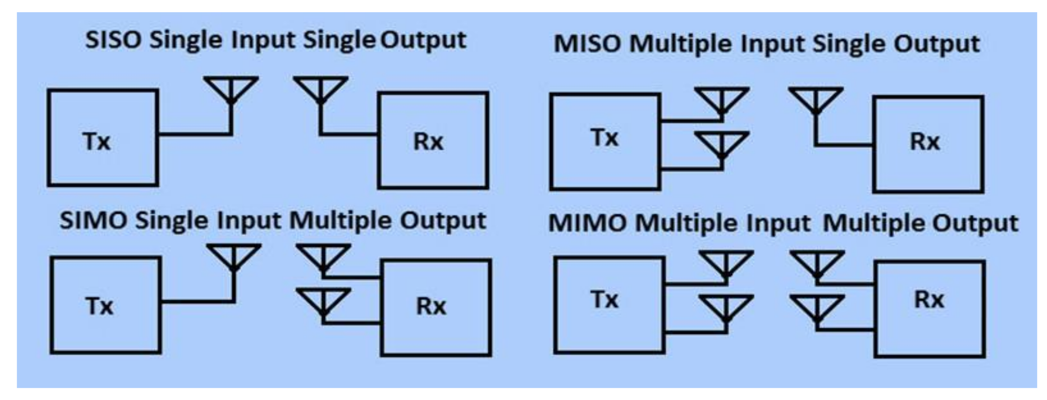
One approach to antenna design is the simultaneous use of several antennas according to MIMO (multiple-input, multiple-output) or MISO (multiple-input, single-output) principles [
18] (
Figure 6). With MISO approaches to antenna systems, MIMO uses two or more antennas to transmit and receive specific frequencies. However, since SDR aims to use a wide frequency range due to communication needs in the maritime environment with various communication systems, it is necessary to create such an interface that can perform this function. An antenna interface will be used as a splitter for separating incoming signals to dedicated channels for direct digitization processing.
4. Application in Maritime Communications
As has already been mentioned earlier, the ship’s communication system consists of many devices with accompanying antennas, each according to its recommended frequency range. A basic system concept for a software-based communication system proposed will have to include different antennas already used onboard, such as VHF, MF/HF, Satcom, UHF, etc. Instead of connecting each antenna to a dedicated communication system, antennas will be connected to a common interface that acts as a front-end part of the direct digitization module. Each antenna is part of one digital processing chain (DPC) so the signals from each antenna are processed separately. The number of DPCs in one direct digitization module will depend on the processing power of the module.
The direct digitization module is an integral part of the software-based communication center, which acts as a GUI for receiving and transmitting different messages, calls and data (
Figure 7). The GUI acting as an HMI enables the user to transfer from one operation mode to another, thereby switching from one frequency band to another depending on the needs. HMI will have to have the ability to serve as a user interface where communication is initiated while also providing insight into system status.
SDR has already found use in military communication systems, from which it derives its foundation, as in the commercial use for certain applications. The application of SDR in the maritime communication domain is somewhat hampered by ITU regulations that are imposed on ship communication equipment. Such regulations not only cover issues of emission class, signal modulation, waveforms, transmission rates, power output, polarization, protocols, etc., but also address antenna heights, power supply requirements, user interface, equipment testing, etc. Satisfying all these requirements for such systems to be considered a solid replacement for current ship communication systems will be a great challenge. Special consideration is also applied to distress functionality that equipment must comply with. Since the GMDSS is developed over a more extended time and is also applied for a longer time period, changes will not be easily made in the existing system. Here, it is necessary to mention that the potential application of SDR within the context of maritime communication should go through a few phases of development, shown in
Figure 8.
In the first phase, communication will be limited to receiving uninitiated communication from shore and base stations in the form of weather reports, navigational warnings and messages, time and safety notifications, and other non-essential and non-formal messages. This phase will be used as an evaluation for different protocols keeping communication only on the data transfer level. The second phase of integration of the communication system marks the transfer to two-way communication of low priority. This phase will introduce besides data transfer also voice communication and outgoing messages communication of low priority. The third development phase introduces full incoming and outgoing communication in all forms, where all communication occurs via a software-based communication system.
5. Conclusions
Maritime communications have been organized for many years by implementing the GMDSS, which is regulated on every level, but there is still room for improvement. One such attempt is the proposed software-based communication center. Even though the implementation itself has physical limitations (antenna system, consuming significant amounts of energy, signal processing speed, etc., unperfected robustness and redundancy), it can still provide a direction to concentrate system development. This proposal views communication systems onboard the vessel as a centralized system where SDR gives some opportunities for achieving this goal. Since implementing the software for digital signal processing or the software-defined radio offers many possibilities, it is necessary to recognize the advantages that would be achieved with the application of SDR in maritime communications. The goal of introducing SDR in maritime communication is to integrate separate communication systems onboard in one mutual communication system. The second important element of introducing SDR concerns simplifying the communication infrastructure onboard a vessel, which, as a consequence, eases the maintenance of the system itself. The third important goal is the simplicity of system upgrading, which will extend the system’s life span, meaning the system’s obsolescence is avoided with a software upgrade.
Issues still arise regarding the technology itself as it is still not robust enough for the maritime environment and does not fully follow the requirements that maritime communication equipment needs to follow. Distress protocols also need to be developed in the case of distress, but user interfaces that should be standardized and the system redundancy conditions are still in the early stages, but they are important issues that must be addressed.


