
Early Biological Valve Failure: Structural Valve Degeneration, Thrombosis, or Endocarditis?
 ,
,  ,
,  , and
, and
Abstract
:
1. Introduction
2. Durability of Biological Heart Valves
3. Using the Correct Terminology: Biological Valve Dysfunction and Biological Valve Failure
4. The Three Enemies of Biological Heart Valves: Structural Degeneration, Thrombosis, and Endocarditis
4.1. Structural Valve Degeneration (Rejection)
4.2. Thrombosis
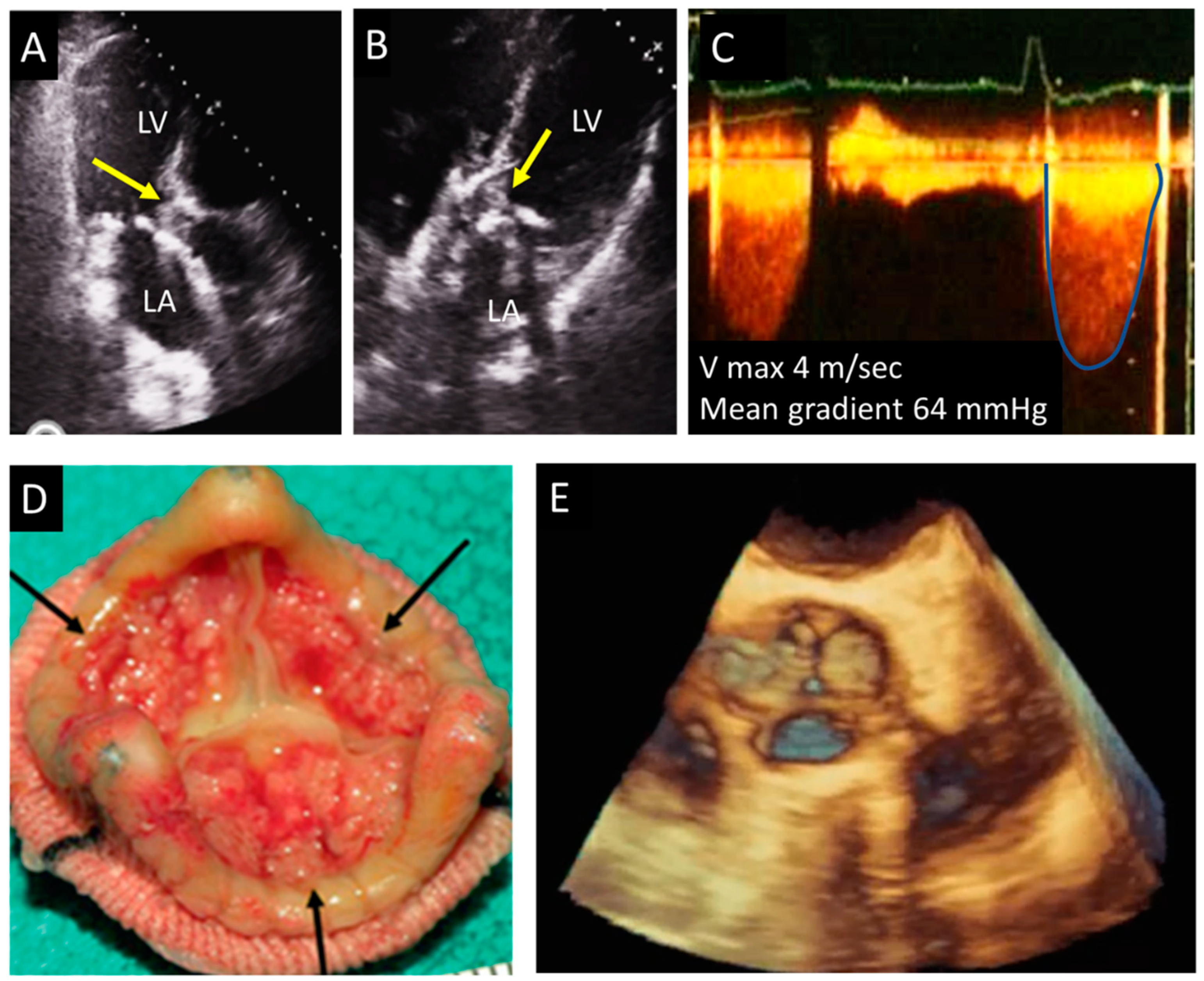
4.3. Endocarditis
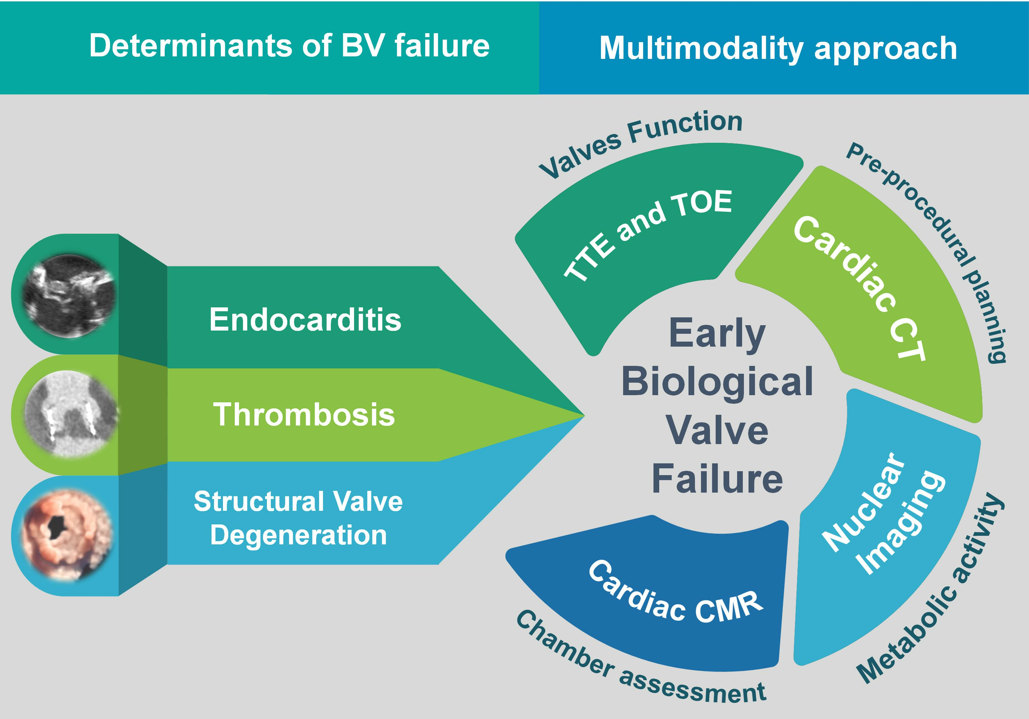
5. How to Distinguish between Valve Degeneration, Thrombosis, and Endocarditis: Integrating Different Imaging Modalities
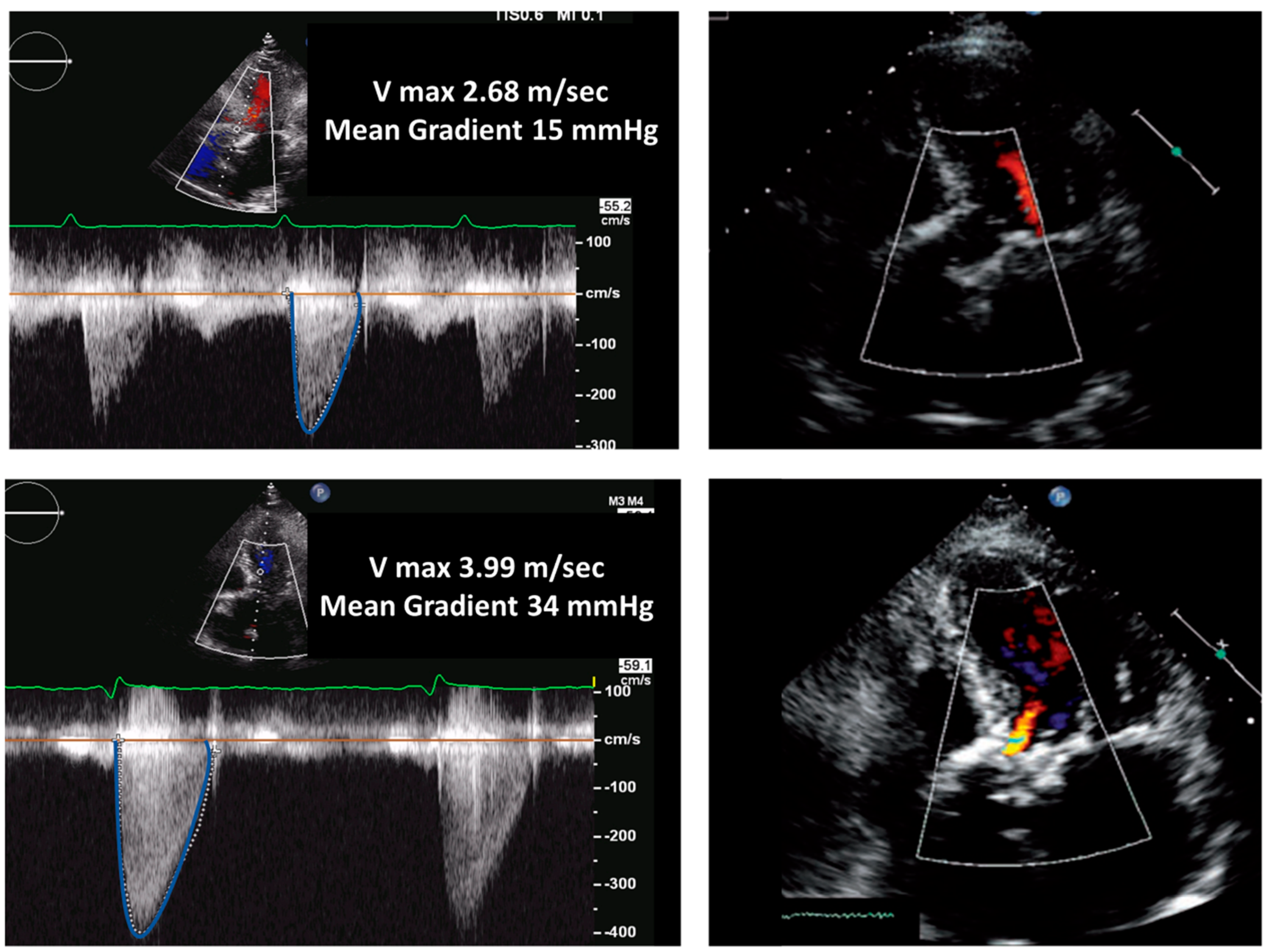
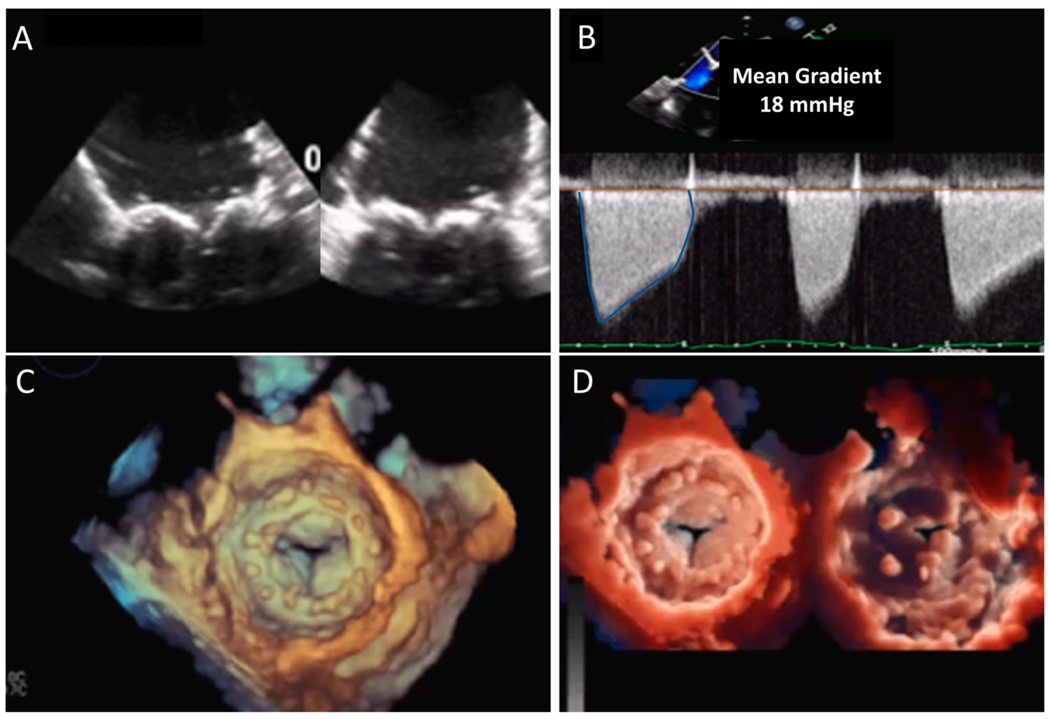
5.1. Echocardiography
5.2. CT
5.3. CMR
5.4. Nuclear Imaging
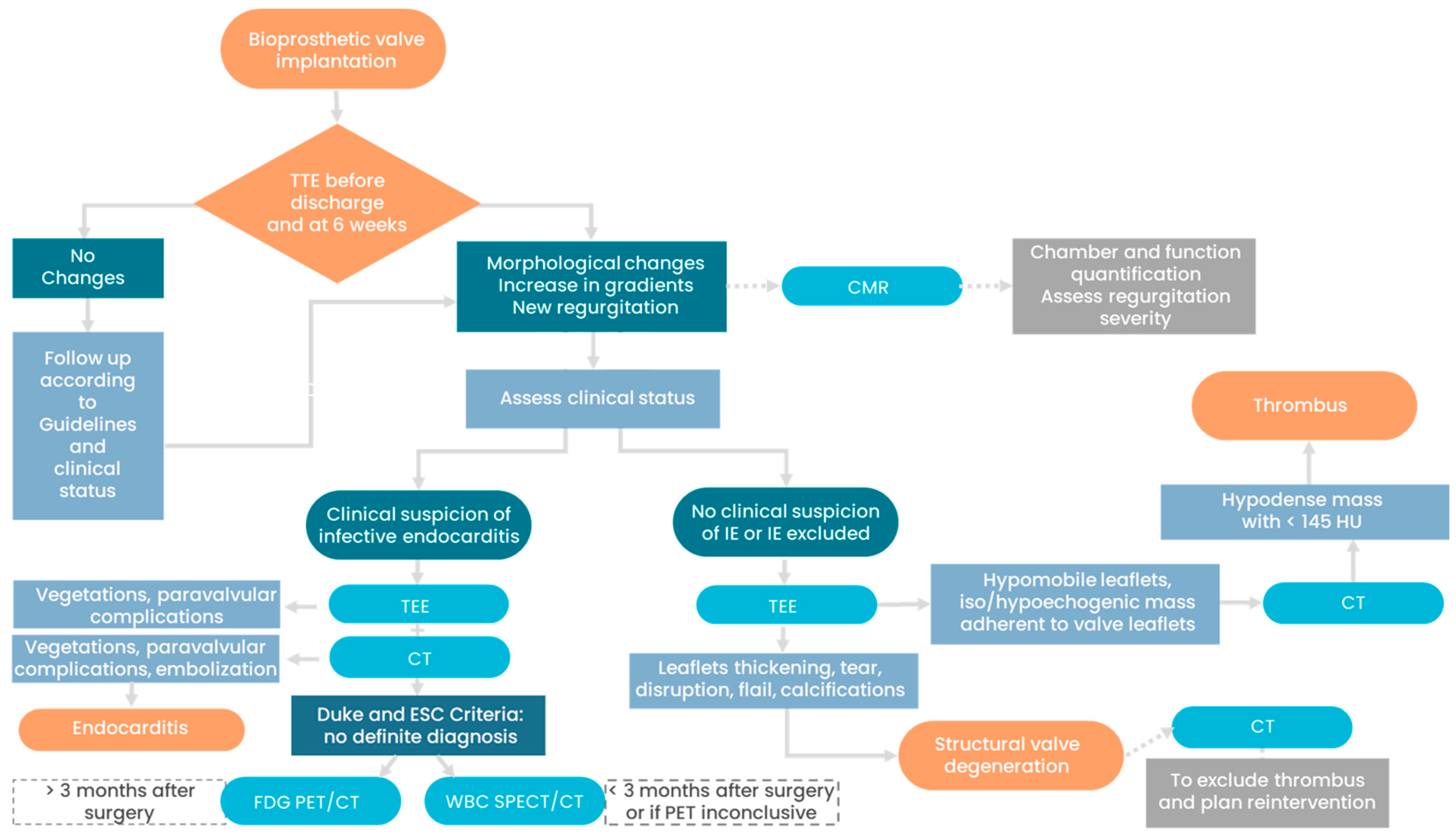
5.5. Management and Prognosis
6. Conclusions
Author Contributions
Funding
Institutional Review Board Statement
Informed Consent Statement
Data Availability Statement
Conflicts of Interest
References
- Brown, J.M.; O’Brien, S.M.; Wu, C.; Sikora, J.A.H.; Griffith, B.P.; Gammie, J.S. Isolated Aortic Valve Replacement in North America Comprising 108,687 Patients in 10 Years: Changes in Risks, Valve Types, and Outcomes in the Society of Thoracic Surgeons National Database. J. Thorac. Cardiovasc. Surg. 2009, 137, 82–90. [Google Scholar] [CrossRef]
- Pibarot, P.; Herrmann, H.C.; Wu, C.; Hahn, R.T.; Otto, C.M.; Abbas, A.E.; Chambers, J.; Dweck, M.R.; Leipsic, J.A.; Simonato, M.; et al. Standardized Definitions for Bioprosthetic Valve Dysfunction Following Aortic or Mitral Valve Replacement: JACC State-of-the-Art Review. J. Am. Coll. Cardiol. 2022, 80, 545–561. [Google Scholar] [CrossRef]
- Rodriguez-Gabella, T.; Voisine, P.; Puri, R.; Pibarot, P.; Rodés-Cabau, J. Aortic Bioprosthetic Valve Durability: Incidence, Mechanisms, Predictors, and Management of Surgical and Transcatheter Valve Degeneration. J. Am. Coll. Cardiol. 2017, 70, 1013–1028. [Google Scholar] [CrossRef] [PubMed]
- Belluschi, I.; Buzzatti, N.; Castiglioni, A.; De Bonis, M.; Maisano, F.; Alfieri, O. Aortic and Mitral Bioprosthetic Valve Dysfunction: Surgical or Percutaneous Solutions? Eur. Heart J. Suppl. 2021, 23, E6–E12. [Google Scholar] [CrossRef] [PubMed]
- Kostyunin, A.E.; Yuzhalin, A.E.; Rezvova, M.A.; Ovcharenko, E.A.; Glushkova, T.V.; Kutikhin, A.G. Degeneration of Bioprosthetic Heart Valves: Update 2020. J. Am. Heart Assoc. 2020, 9, e018506. [Google Scholar] [CrossRef] [PubMed]
- Morris, A.H.; Stamer, D.K.; Kyriakides, T.R. The Host Response to Naturally-Derived Extracellular Matrix Biomaterials. Semin. Immunol. 2017, 29, 72–91. [Google Scholar] [CrossRef] [PubMed]
- Capodanno, D.; Petronio, A.S.; Prendergast, B.; Eltchaninoff, H.; Vahanian, A.; Modine, T.; Lancellotti, P.; Sondergaard, L.; Ludman, P.F.; Tamburino, C.; et al. Standardized Definitions of Structural Deterioration and Valve Failure in Assessing Long-Term Durability of Transcatheter and Surgical Aortic Bioprosthetic Valves: A Consensus Statement from the European Association of Percutaneous Cardiovascular Interven. Eur. J. Cardio-thoracic Surg. 2017, 52, 408–417. [Google Scholar] [CrossRef]
- Puvimanasinghe, J.P.A.; Steyerberg, E.W.; Takkenberg, J.J.M.; Eijkemans, M.J.C.; Van Herwerden, L.A.; Bogers, A.J.J.C.; Habbema, J.D.F. Prognosis after Aortic Valve Replacement with a Bioprosthesis: Predictions Based on Meta-Analysis and Microsimulation. Circulation 2001, 103, 1535–1541. [Google Scholar] [CrossRef]
- Dangas, G.D.; Weitz, J.I.; Giustino, G.; Makkar, R.; Mehran, R. Prosthetic Heart Valve Thrombosis. J. Am. Coll. Cardiol. 2016, 68, 2670–2689. [Google Scholar] [CrossRef]
- Turbill, P.; Beugeling, T.; Poot, A.A. Proteins Involved in the Vroman Effect during Exposure of Human Blood Plasma to Glass and Polyethylene. Biomaterials 1996, 17, 1279–1287. [Google Scholar] [CrossRef]
- Bax, J.J.; Delgado, V. Bioprosthetic Heart Valves, Thrombosis, Anticoagulation, and Imaging Surveillance. JACC Cardiovasc. Interv. 2017, 10, 388–390. [Google Scholar] [CrossRef] [PubMed]
- Muratori, M.; Fusini, L.; Mancini, M.E.; Tamborini, G.; Ali, S.G.; Gripari, P.; Doldi, M.; Frappampina, A.; Teruzzi, G.; Pontone, G.; et al. The Role of Multimodality Imaging in Left-Sided Prosthetic Valve Dysfunction. J. Cardiovasc. Dev. Dis. 2022, 9, 12. [Google Scholar] [CrossRef]
- Francone, M.; Budde, R.P.J.; Bremerich, J.; Dacher, J.N.; Loewe, C.; Wolf, F.; Natale, L.; Pontone, G.; Redheuil, A.; Vliegenthart, R.; et al. CT and MR Imaging Prior to Transcatheter Aortic Valve Implantation: Standardisation of Scanning Protocols, Measurements and Reporting—A Consensus Document by the European Society of Cardiovascular Radiology (ESCR). Eur. Radiol. 2020, 30, 2627–2650. [Google Scholar] [CrossRef] [PubMed]
- Makkar, R.R.; Blanke, P.; Leipsic, J.; Thourani, V.; Chakravarty, T.; Brown, D.; Trento, A.; Guyton, R.; Babaliaros, V.; Williams, M.; et al. Subclinical Leaflet Thrombosis in Transcatheter and Surgical Bioprosthetic Valves: PARTNER 3 Cardiac Computed Tomography Substudy. J. Am. Coll. Cardiol. 2020, 75, 3003–3015. [Google Scholar] [CrossRef] [PubMed]
- Shahinian, J.H.; Chan, V.; Pislaru, S.V. Chronic Thrombosis of Bioprostheses: Diagnosis and Management. Prog. Cardiovasc. Dis. 2022, 72, 15–20. [Google Scholar] [CrossRef] [PubMed]
- Bax, J.J.; Delgado, V. Prosthetic Valve Endocarditis after Surgical and Transcatheter Aortic Valve Replacement: Infrequent, but Poor Outcome. EuroIntervention 2019, 15, e484–e485. [Google Scholar] [CrossRef] [PubMed]
- Moriyama, N.; Laakso, T.; Biancari, F.; Raivio, P.; Jalava, M.P.; Jaakkola, J.; Dahlbacka, S.; Kinnunen, E.M.; Juvonen, T.; Husso, A.; et al. Prosthetic Valve Endocarditis after Transcatheter or Surgical Aortic Valve Replacement with a Bioprosthesis: Results from the FinnValve Registry. EuroIntervention 2019, 15, E500–E507. [Google Scholar] [CrossRef]
- Erba, P.A.; Pizzi, M.N.; Roque, A.; Salaun, E.; Lancellotti, P.; Tornos, P.; Habib, G. Multimodality Imaging in Infective Endocarditis: An Imaging Team Within the Endocarditis Team. Circulation 2019, 140, 1753–1765. [Google Scholar] [CrossRef]
- Habib, G.; Lancellotti, P.; Antunes, M.J.; Bongiorni, M.G.; Casalta, J.P.; Del Zotti, F.; Dulgheru, R.; El Khoury, G.; Erba, P.A.; Iung, B.; et al. 2015 ESC Guidelines for the Management of Infective Endocarditis. Eur. Heart J. 2015, 36, 3075–3123. [Google Scholar] [CrossRef]
- Lancellotti, P.; Pibarot, P.; Chambers, J.; Edvardsen, T.; Delgado, V.; Dulgheru, R.; Pepi, M.; Cosyns, B.; Dweck, M.R.; Garbi, M.; et al. Recommendations for the Imaging Assessment of Prosthetic Heart Valves: A Report from the European Association of Cardiovascular Imaging Endorsed by the Chinese Society of Echocardiography, the Inter-American Society of Echocardiography, and the Brazilian. Eur. Heart J. Cardiovasc. Imaging 2016, 17, 589–590. [Google Scholar] [CrossRef]
- Hill, E.E.; Herijgers, P.; Claus, P.; Vanderschueren, S.; Peetermans, W.E.; Herregods, M.C. Abscess in Infective Endocarditis: The Value of Transesophageal Echocardiography and Outcome: A 5-Year Study. Am. Heart J. 2007, 154, 923–928. [Google Scholar] [CrossRef] [PubMed]
- Østergaard, L.; Vejlstrup, N.; Køber, L.; Fosbøl, E.L.; Søndergaard, L.; Ihlemann, N. Diagnostic Potential of Intracardiac Echocardiography in Patients with Suspected Prosthetic Valve Endocarditis. J. Am. Soc. Echocardiogr. 2019, 32, 1558–1564.e3. [Google Scholar] [CrossRef] [PubMed]
- Harding, D.; Cahill, T.J.; Redwood, S.R.; Prendergast, B.D. Infective Endocarditis Complicating Transcatheter Aortic Valve Implantation. Heart 2020, 106, 493–498. [Google Scholar] [CrossRef] [PubMed]
- Gripari, P.; Ewe, S.H.; Fusini, L.; Muratori, M.; Ng, A.C.T.; Cefalú, C.; Delgado, V.; Schalij, M.J.; Bax, J.J.; Marsan, N.A.; et al. Intraoperative 2D and 3D Transoesophageal Echocardiographic Predictors of Aortic Regurgitation after Transcatheter Aortic Valve Implantation. Heart 2012, 98, 1229–1236. [Google Scholar] [CrossRef] [PubMed]
- Alexis, S.L.; Malik, A.H.; George, I.; Hahn, R.T.; Khalique, O.K.; Seetharam, K.; Bhatt, D.L.; Tang, G.H. Infective Endocarditis After Surgical and Transcatheter Aortic Valve Replacement: A State of the Art Review. J. Am. Heart Assoc. 2020, 9, 17347. [Google Scholar] [CrossRef]
- Wahadat, A.R.; Tanis, W.; Swart, L.E.; Scholtens, A.; Krestin, G.P.; van Mieghem, N.M.D.A.; Schurink, C.A.M.; van der Spoel, T.I.G.; van den Brink, F.S.; Vossenberg, T.; et al. Added Value of 18F-FDG-PET/CT and Cardiac CTA in Suspected Transcatheter Aortic Valve Endocarditis. J. Nucl. Cardiol. 2021, 28, 2072–2082. [Google Scholar] [CrossRef]
- Saeedan, M.B.; Wang, T.K.M.; Cremer, P.; Wahadat, A.R.; Budde, R.P.J.; Unai, S.; Pettersson, G.B.; Bolen, M.A. Role of Cardiac Ct in Infective Endocarditis: Current Evidence, Opportunities, and Challenges. Radiol. Cardiothorac. Imaging 2021, 3, e200378. [Google Scholar] [CrossRef]
- Vahanian, A.; Beyersdorf, F.; Praz, F.; Milojevic, M.; Baldus, S.; Bauersachs, J.; Capodanno, D.; Conradi, L.; De Bonis, M.; De Paulis, R.; et al. 2021 ESC/EACTS Guidelines for the Management of Valvular Heart Disease: Developed by the Task Force for the Management of Valvular Heart Disease of the European Society of Cardiology (ESC) and the European Association for Cardio-Thoracic Surgery (EACTS). Rev. Esp. Cardiol. 2022, 75, 524. [Google Scholar] [CrossRef]
- Chambers, J.B.; Garbi, M.; Nieman, K.; Myerson, S.; Pierard, L.A.; Habib, G.; Zamorano, J.L.; Edvardsen, T.; Lancellotti, P.; Delgado, V.; et al. Appropriateness Criteria for the Use of Cardiovascular Imaging in Heart Valve Disease in Adults: A European Association of Cardiovascular Imaging Report of Literature Review and Current Practice. Eur. Heart J. Cardiovasc. Imaging 2017, 18, 489–498. [Google Scholar] [CrossRef]
- Dvir, D.; Bourguignon, T.; Otto, C.M.; Hahn, R.T.; Rosenhek, R.; Webb, J.G.; Treede, H.; Sarano, M.E.; Feldman, T.; Wijeysundera, H.C.; et al. Standardized Definition of Structural Valve Degeneration for Surgical and Transcatheter Bioprosthetic Aortic Valves. Circulation 2018, 137, 388–399. [Google Scholar] [CrossRef]
- Salaun, E.; Clavel, M.A.; Rodés-Cabau, J.; Pibarot, P. Bioprosthetic Aortic Valve Durability in the Era of Transcatheter Aortic Valve Implantation. Heart 2018, 104, 1323–1332. [Google Scholar] [CrossRef] [PubMed]
- Daniel, W.G.; Mügge, A.; Grote, J.; Hausmann, D.; Nikutta, P.; Laas, J.; Lichtlen, P.R.; Martin, R.P. Comparison of Transthoracic and Transesophageal Echocardiography for Detection of Abnormalities of Prosthetic and Bioprosthetic Valves in the Mitral and Aortic Positions. Am. J. Cardiol. 1993, 71, 210–215. [Google Scholar] [CrossRef] [PubMed]
- Saleeb, S.F.; Newburger, J.W.; Geva, T.; Baird, C.W.; Gauvreau, K.; Padera, R.F.; Del Nido, P.J.; Borisuk, M.J.; Sanders, S.P.; Mayer, J.E. Accelerated Degeneration of a Bovine Pericardial Bioprosthetic Aortic Valve in Children and Young Adults. Circulation 2014, 130, 51–60. [Google Scholar] [CrossRef] [PubMed]
- Jilaihawi, H.; Makkar, R.R.; Kashif, M.; Okuyama, K.; Chakravarty, T.; Shiota, T.; Friede, G.; Nakamura, M.; Doctor, N.; Rafique, A.; et al. A Revised Methodology for Aortic-Valvar Complex Calcium Quantification for Transcatheter Aortic Valve Implantation. Eur. Heart J. Cardiovasc. Imaging 2014, 15, 1324–1332. [Google Scholar] [CrossRef] [PubMed]
- Gündüz, S.; Özkan, M.; Kalçik, M.; Gürsoy, O.M.; Astarcioğlu, M.A.; Karakoyun, S.; Aykan, A.Ç.; Biteker, M.; Gökdeniz, T.; Kaya, H.; et al. Sixty-Four-Section Cardiac Computed Tomography in Mechanical Prosthetic Heart Valve Dysfunction: Thrombus or Pannus. Circ. Cardiovasc. Imaging 2015, 8, e003246. [Google Scholar] [CrossRef] [PubMed]
- Jilaihawi, H.; Asch, F.M.; Manasse, E.; Ruiz, C.E.; Jelnin, V.; Kashif, M.; Kawamori, H.; Maeno, Y.; Kazuno, Y.; Takahashi, N.; et al. Systematic CT Methodology for the Evaluation of Subclinical Leaflet Thrombosis. JACC Cardiovasc. Imaging 2017, 10, 461–470. [Google Scholar] [CrossRef] [PubMed]
- Makkar, R.R.; Fontana, G.; Jilaihawi, H.; Chakravarty, T.; Kofoed, K.F.; De Backer, O.; Asch, F.M.; Ruiz, C.E.; Olsen, N.T.; Trento, A.; et al. Possible Subclinical Leaflet Thrombosis in Bioprosthetic Aortic Valves. N. Engl. J. Med. 2015, 373, 2015–2024. [Google Scholar] [CrossRef]
- Chaosuwannakit, N.; Makarawate, P. Value of Cardiac Computed Tomography Angiography in Pre-Operative Assessment of Infective Endocarditis. J. Cardiothorac. Surg. 2019, 14, 56. [Google Scholar] [CrossRef]
- Habets, J.; Tanis, W.; Van Herwerden, L.A.; Van Den Brink, R.B.A.; Mali, W.P.T.M.; De Mol, B.A.J.M.; Chamuleau, S.A.J.; Budde, R.P.J. Cardiac Computed Tomography Angiography Results in Diagnostic and Therapeutic Change in Prosthetic Heart Valve Endocarditis. Int. J. Cardiovasc. Imaging 2013, 30, 377–387. [Google Scholar] [CrossRef]
- Shellock, F.G. Prosthetic Heart Valves and Annuloplasty Rings: Assessment of Magnetic Field Interactions, Heating, and Artifacts at 1.5 Tesla. J. Cardiovasc. Magn. Reson. 2001, 3, 317–324. [Google Scholar] [CrossRef]
- Mgbojikwe, N.; Jones, S.R.; Leucker, T.M.; Brotman, D.J. Infective Endocarditis: Beyond the Usual Tests. Cleve. Clin. J. Med. 2019, 86, 559–567. [Google Scholar] [CrossRef]
- Wang, T.K.M.; Griffin, B.; Cremer, P.; Shrestha, N.; Gordon, S.; Pettersson, G.; Desai, M. Diagnostic Utility of CT and MRI for Mycotic Aneurysms: A Meta-Analysis. Am. J. Roentgenol. 2020, 215, 1257–1266. [Google Scholar] [CrossRef] [PubMed]
- Pazos-López, P.; Pozo, E.; Siqueira, M.E.; García-Lunar, I.; Cham, M.; Jacobi, A.; Macaluso, F.; Fuster, V.; Narula, J.; Sanz, J. Value of CMR for the Differential Diagnosis of Cardiac Masses. JACC Cardiovasc. Imaging 2014, 7, 896–905. [Google Scholar] [CrossRef] [PubMed]
- Fazzari, F.; Figliozzi, S.; Bragato, R.M.; Monti, L. A Huge Atrial Thrombus in a Patient with Bioprosthetic Valve and Atrial Fibrillation: Something Went Wrong with Anticoagulation Therapy. Eur. Heart J. 2021, 42, 2315. [Google Scholar] [CrossRef]
- Rouzet, F.; Chequer, R.; Benali, K.; Lepage, L.; Ghodbane, W.; Duval, X.; Iung, B.; Vahanian, A.; Le Guludec, D.; Hyafil, F. Respective Performance of 18F-FDG PET and Radiolabeled Leukocyte Scintigraphy for the Diagnosis of Prosthetic Valve Endocarditis. J. Nucl. Med. 2014, 55, 1980–1985. [Google Scholar] [CrossRef]
- Pizzi, M.N.; Roque, A.; Fernández-Hidalgo, N.; Cuéllar-Calabria, H.; Ferreira-González, I.; Gonzàlez-Alujas, M.T.; Oristrell, G.; Gracia-Sánchez, L.; González, J.J.; Rodríguez-Palomares, J.; et al. Improving the Diagnosis of Infective Endocarditis in Prosthetic Valves and Intracardiac Devices with 18F-Fluordeoxyglucose Positron Emission Tomography/Computed Tomography Angiography: Initial Results at an Infective Endocarditis Referral Center. Circulation 2015, 132, 1113–1126. [Google Scholar] [CrossRef] [PubMed]
- Habib, G.; Erba, P.A.; Iung, B.; Donal, E.; Cosyns, B.; Laroche, C.; Popescu, B.A.; Prendergast, B.; Tornos, P.; Sadeghpour, A.; et al. Clinical Presentation, Aetiology and Outcome of Infective Endocarditis. Results of the ESC-EORP EURO-ENDO (European Infective Endocarditis) Registry: A Prospective Cohort Study. Eur. Heart J. 2019, 40, 3222–3232. [Google Scholar] [CrossRef] [PubMed]
- Presti, S.L.; Elajami, T.K.; Zmaili, M.; Reyaldeen, R.; Xu, B. Multimodality Imaging in the Diagnosis and Management of Prosthetic Valve Endocarditis: A Contemporary Narrative Review. World J. Cardiol. 2021, 13, 254–270. [Google Scholar] [CrossRef] [PubMed]
- Dweck, M.R.; Jenkins, W.S.A.; Vesey, A.T.; Pringle, M.A.H.; Chin, C.W.L.; Malley, T.S.; Cowie, W.J.A.; Tsampasian, V.; Richardson, H.; Fletcher, A.; et al. 18F-Sodium Fluoride Uptake Is a Marker of Active Calcification and Disease Progression in Patients with Aortic Stenosis. Circ. Cardiovasc. Imaging 2014, 7, 371–378. [Google Scholar] [CrossRef]
- Cartlidge, T.R.G.; Doris, M.K.; Sellers, S.L.; Pawade, T.A.; White, A.C.; Pessotto, R.; Kwiecinski, J.; Fletcher, A.; Alcaide, C.; Lucatelli, C.; et al. Detection and Prediction of Bioprosthetic Aortic Valve Degeneration. J. Am. Coll. Cardiol. 2019, 73, 1107–1119. [Google Scholar] [CrossRef]
- Kwiecinski, J.; Tzolos, E.; Cartlidge, T.R.G.; Fletcher, A.; Doris, M.K.; Bing, R.; Tarkin, J.M.; Seidman, M.A.; Gulsin, G.S.; Cruden, N.L.; et al. Native Aortic Valve Disease Progression and Bioprosthetic Valve Degeneration in Patients With Transcatheter Aortic Valve Implantation. Circulation 2021, 144, 1396–1408. [Google Scholar] [CrossRef] [PubMed]
- Habets, J.; Tanis, W.; Reitsma, J.B.; van den Brink, R.B.; Mali, W.P.; Chamuleau, S.A.; Budde, R.P. Are Novel Non-Invasive Imaging Techniques Needed in Patients with Suspected Prosthetic Heart Valve Endocarditis? A Systematic Review and Meta-Analysis. Eur. Radiol. 2015, 25, 2125–2133. [Google Scholar] [CrossRef] [PubMed]
- Wang, A.; Athan, E.; Pappas, P.A.; Fowler, V.G.; Olaison, L.; Paré, C.; Almirante, B.; Muñoz, P.; Rizzi, M.; Naber, C.; et al. Contemporary Clinical Profile and Outcome of Prosthetic Valve Endocarditis. JAMA 2007, 297, 1354–1361. [Google Scholar] [CrossRef] [PubMed]
- Balsam, L.B.; Grossi, E.A.; Greenhouse, D.G.; Ursomanno, P.; Deanda, A.; Ribakove, G.H.; Culliford, A.T.; Galloway, A.C. Reoperative Valve Surgery in the Elderly: Predictors of Risk and Long-Term Survival. Ann. Thorac. Surg. 2010, 90, 1195–1201. [Google Scholar] [CrossRef]
- Blanche, C.; Khan, S.S.; Chaux, A.; Denton, T.A.; Sandhu, M.; Tsai, T.P.; Trento, A. Cardiac Reoperations in Octogenarians: Analysis of Outcomes. Ann. Thorac. Surg. 1999, 67, 93–98. [Google Scholar] [CrossRef] [PubMed]
- Leontyev, S.; Borger, M.A.; Davierwala, P.; Walther, T.; Lehmann, S.; Kempfert, J.; Mohr, F.W. Redo Aortic Valve Surgery: Early and Late Outcomes. Ann. Thorac. Surg. 2011, 91, 1120–1126. [Google Scholar] [CrossRef]
- Paradis, J.M.; Del Trigo, M.; Puri, R.; Rodés-Cabau, J. Transcatheter Valve-in-Valve and Valve-in-Ring for Treating Aortic and Mitral Surgical Prosthetic Dysfunction. J. Am. Coll. Cardiol. 2015, 66, 2019–2037. [Google Scholar] [CrossRef]
- Rajiah, P.; Schoenhagen, P. The Role of Computed Tomography in Pre-Procedural Planning of Cardiovascular Surgery and Intervention. Insights Imaging 2013, 4, 671–689. [Google Scholar] [CrossRef]
- Blanke, P.; Weir-McCall, J.R.; Achenbach, S.; Delgado, V.; Hausleiter, J.; Jilaihawi, H.; Marwan, M.; Nørgaard, B.L.; Piazza, N.; Schoenhagen, P.; et al. Computed Tomography Imaging in the Context of Transcatheter Aortic Valve Implantation (TAVI)/Transcatheter Aortic Valve Replacement (TAVR): An Expert Consensus Document of the Society of Cardiovascular Computed Tomography. JACC Cardiovasc. Imaging 2019, 12, 1–24. [Google Scholar] [CrossRef]
- Ge, Y.; Gupta, S.; Fentanes, E.; Aghayev, A.; Steigner, M.; Sobieszczyk, P.; Kaneko, T.; Di Carli, M.F.; Bhatt, D.L.; Shah, P.; et al. Role of Cardiac CT in Pre-Procedure Planning for Transcatheter Mitral Valve Replacement. JACC Cardiovasc. Imaging 2021, 14, 1571–1580. [Google Scholar] [CrossRef]
- Blanke, P.; Naoum, C.; Dvir, D.; Bapat, V.; Ong, K.; Muller, D.; Cheung, A.; Ye, J.; Min, J.K.; Piazza, N.; et al. Predicting LVOT Obstruction in Transcatheter Mitral Valve Implantation: Concept of the Neo-LVOT. JACC Cardiovasc. Imaging 2017, 10, 482–485. [Google Scholar] [CrossRef] [PubMed]
- Meduri, C.U.; Reardon, M.J.; Lim, D.S.; Howard, E.; Dunnington, G.; Lee, D.P.; Liang, D.; Gooley, R.; O’Hair, D.; Ng, M.K.; et al. Novel Multiphase Assessment for Predicting Left Ventricular Outflow Tract Obstruction Before Transcatheter Mitral Valve Replacement. JACC Cardiovasc. Interv. 2019, 12, 2402–2412. [Google Scholar] [CrossRef] [PubMed]
- Hanson, R.; Nyman, C.; Shook, D.C.; Huang, C.C.; Kaneko, T.; Shah, P.B.; Fox, J.A.; Shernan, S. Identifying Patients at Risk for LVOT Obstruction in Mitral Valve-in-Valve Implantation. JACC Cardiovasc. Imaging 2017, 10, 89–91. [Google Scholar] [CrossRef] [PubMed]
- Murphy, D.J.; Ge, Y.; Don, C.W.; Keraliya, A.; Aghayev, A.; Morgan, R.; Galper, B.; Bhatt, D.L.; Kaneko, T.; Di Carli, M.; et al. Use of Cardiac Computerized Tomography to Predict Neo-Left Ventricular Outflow Tract Obstruction before Transcatheter Mitral Valve Replacement. J. Am. Heart Assoc. 2017, 6, e007353. [Google Scholar] [CrossRef]


| Typical Features | Structural Valve Degeneration | Thrombosis | Endocarditis |
|---|---|---|---|
| Anatomopathological | Dystrophic calcifications, macrophages, platelet and leukocyte infiltration, and inflammatory tissue overgrowth (pannus). | Fresh or chronic thrombi adherent to leaflets’ surface may be associated with leaflets’ surface damage. | Vegetations adherent to upstream surface of valve leaflets, made of inflammatory cells and microorganisms. Paravalvular disruption. |
| Clinical | Usually late onset of symptoms (5–10 years after surgery) and slow progression of BV dysfunction at serial monitoring. | Subclinical thrombosis is an incidental finding (spontaneous resolution in 50% of cases). Clinical thrombosis: heart-failure symptoms and thromboembolic events. | Staphylococci endocarditis (first year after surgery); other microorganisms (late onset). Fever and symptoms of infection precede rapid onset of HF symptoms. Thromboembolic events. |
| TTE, TEE | Leaflet and/or ring thickening with diffuse or focal hyperechogenicity (calcifications). Reduced leaflet mobility. Leaflets’ fenestration, avulsion, or perforation. Stenosis or regurgitation. | Iso-hypoechogenic mass adherent to leaflets and ring, with leaflet thickening. Normal or reduced cusp mobility. More often, stenosis; regurgitation is uncommon. | Vegetations, diffuse or focal leaflets thickening, cusps perforation, wear or tear or cusp avulsion. Vegetation motion independent to cusps motion. Paravalvular complications: abscess, pseudo-aneurysm, fistula or dehiscence (and in some cases valve rocking) |
| CCT | Pannus (hypodense): HU ≥ 145; semicircular or circular structure located along leaflets’ surface or stent. Hyperdense leaflet thickening with or without calcifications, along with or without reduced mobility. | No calcifications. HU < 145. Hypoattenuated leaflet thickening (HALT), affecting (HAM) or reducing (RLM) leaflet motion. In some cases, large hypoattenuated mass. | Hypoattenuated mass adherent to leaflets or stent. Paravalvular complications: abscess, pseudo-aneurysm, fistula, or dehiscence. |
| CMR | Limited role in anatomical definition. Quantification of chambers volume and function. Quantification of stenosis and regurgitation (when echo is not feasible). | Non-enhancing mass during first pass with hypointense border and brighter central zone at LGE sequences. | Small and highly mobile vegetations are not visible. Main use to detect extracardiac manifestations (cerebral and aortic). |
| PET/CT or SPECT/CT | No BV or pannus 18FDG uptake. Possible 18F Na uptake of BV leaflets. | Possible 18F Na uptake of BV leaflets. | Increased 18FDG uptake of BV leaflets, paravalvular regions, and metastatic foci. |
| SVD Stages | Aortic Valve Bioprosthesis | Mitral Valve Bioprosthesis |
|---|---|---|
| Stage 1 | Morphological valve deterioration without hemodynamic impairment. | Morphological valve deterioration without hemodynamic impairment. |
| Vmax: <3 m/s; Mean gradient < 20 mmHg, with an increase in mean gradient during follow-up < 10 mmHg; DVI > 0.35; AT < 100 ms; AT/ET < 0.32; EOA > 1.2 cm2 for BSA < 1.6 m2; EOA > 1 cm2 for BSA < 1.6 m2. | Mean gradient < 5 mmHg; DVI < 0.4; MVA > 1.5 cm2. | |
| Stage 2 | Morphological valve deterioration plus one of the following: | Morphological valve deterioration plus one of the following: |
| Vmax: 3–4 m/s; Mean gradient: 20–40 mmHg, with an increase in mean gradient during follow-up between 10 and 20 mmHg; DVI between 0.25 and 0.35; AT between 80 and 100 ms; AT/ET between 0.32 and 0.37; EOA between 1 and 1.2 cm2 for BSA < 1.6 m2; EOA between 0.8 and 1.1 cm2 for BSA > 1.6 m2; Moderate regurgitation. | Increase in DVI ≥ 0.4 or ≥20% resulting in DVI ≥ 2.2; Decrease in MVA ≥ 0.5 cm2 or ≥25% resulting in MVA < 1.5 cm2, compared with echocardiographic assessment performed post-surgery; Mean gradient > 5 mmHg; Moderate regurgitation. | |
| Stage 3 | Morphological valve deterioration plus one of the following: | Morphological valve deterioration plus one of the following: |
| Vmax > 4 m/s; Mean gradient > 40 mmHg, with an increase in mean gradient > 20 mmHg during follow-up; AT > 100 ms; AT/ET > 0.37; EOA < 1 cm2 for BSA < 1.6 m2; EOA < 0.8 cm2 for BSA > 1.6 m2. Severe regurgitation | Increase in DVI ≥ 0.8 or ≥ 40% resulting in DVI ≥ 2.5; Decrease in MVA ≥ 1.0 cm2 or ≥50% resulting in MVA < 1.0 cm2, compared to echocardiographic assessment performed post-surgery; Mean gradient > 10 mm Hg during follow-up; Severe regurgitation. |
Disclaimer/Publisher’s Note: The statements, opinions and data contained in all publications are solely those of the individual author(s) and contributor(s) and not of MDPI and/or the editor(s). MDPI and/or the editor(s) disclaim responsibility for any injury to people or property resulting from any ideas, methods, instructions or products referred to in the content. |
© 2023 by the authors. Licensee MDPI, Basel, Switzerland. This article is an open access article distributed under the terms and conditions of the Creative Commons Attribution (CC BY) license (https://creativecommons.org/licenses/by/4.0/).
Share and Cite
Fazzari, F.; Baggiano, A.; Fusini, L.; Ghulam Ali, S.; Gripari, P.; Junod, D.; Mancini, M.E.; Maragna, R.; Mushtaq, S.; Pontone, G.; et al. Early Biological Valve Failure: Structural Valve Degeneration, Thrombosis, or Endocarditis? J. Clin. Med. 2023, 12, 5740. https://doi.org/10.3390/jcm12175740
Fazzari F, Baggiano A, Fusini L, Ghulam Ali S, Gripari P, Junod D, Mancini ME, Maragna R, Mushtaq S, Pontone G, et al. Early Biological Valve Failure: Structural Valve Degeneration, Thrombosis, or Endocarditis? Journal of Clinical Medicine. 2023; 12(17):5740. https://doi.org/10.3390/jcm12175740
Chicago/Turabian StyleFazzari, Fabio, Andrea Baggiano, Laura Fusini, Sarah Ghulam Ali, Paola Gripari, Daniele Junod, Maria Elisabetta Mancini, Riccardo Maragna, Saima Mushtaq, Gianluca Pontone, and et al. 2023. "Early Biological Valve Failure: Structural Valve Degeneration, Thrombosis, or Endocarditis?" Journal of Clinical Medicine 12, no. 17: 5740. https://doi.org/10.3390/jcm12175740