Perfluoropolymer/Molecular Sieve Mixed-Matrix Membranes


Abstract
:1. Introduction
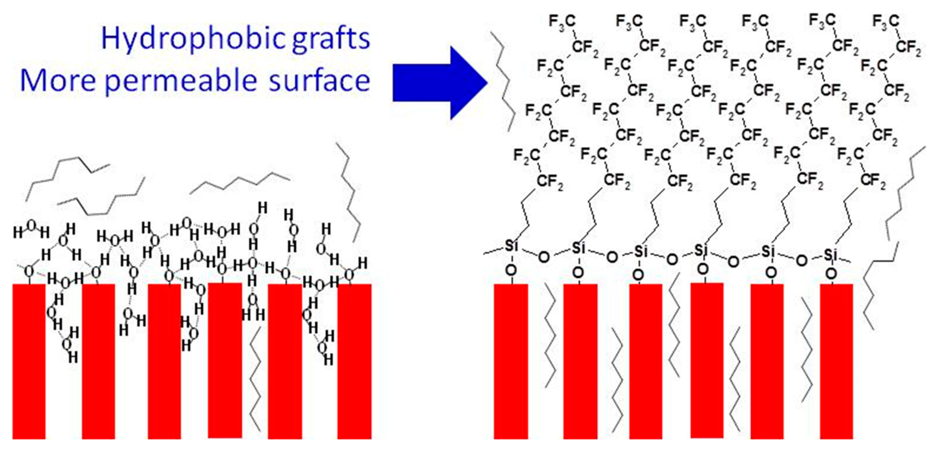
2. Surface Modification of Molecular Sieves and Surface Permeability
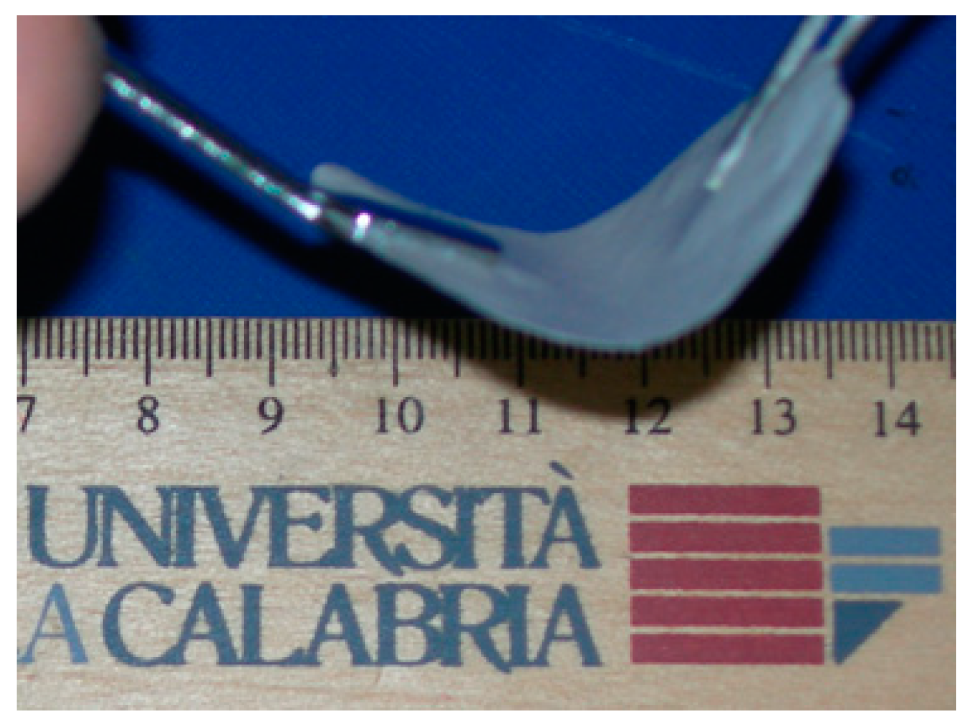
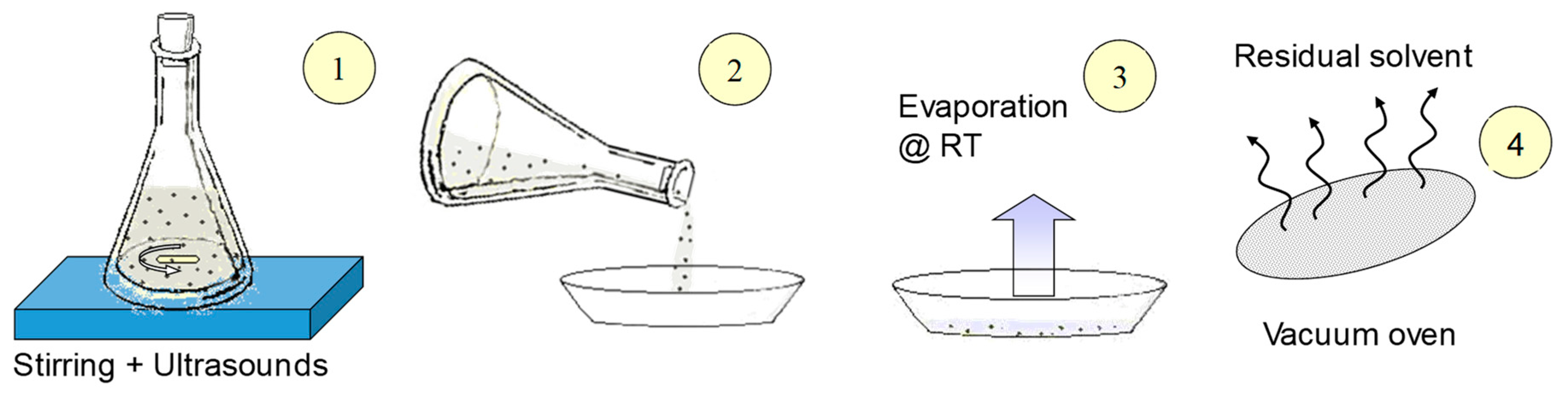
3. Preparation of Hydrophobic PFP/Molecular Sieve MMMs
4. Transport Properties of Hydrophobic PFP/Molecular Sieve MMMs
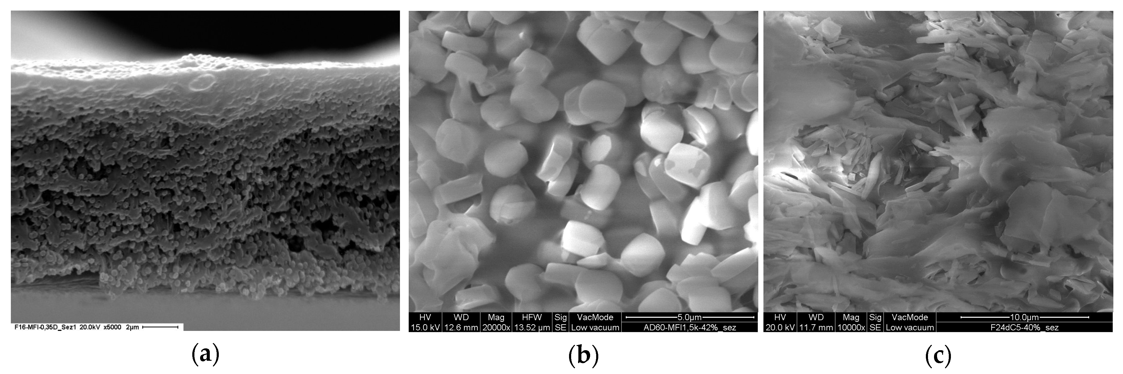
4.1. PFP/Silicalite-1 MMMs
4.1.1. Derivation of the Permeability of Silicalite-1
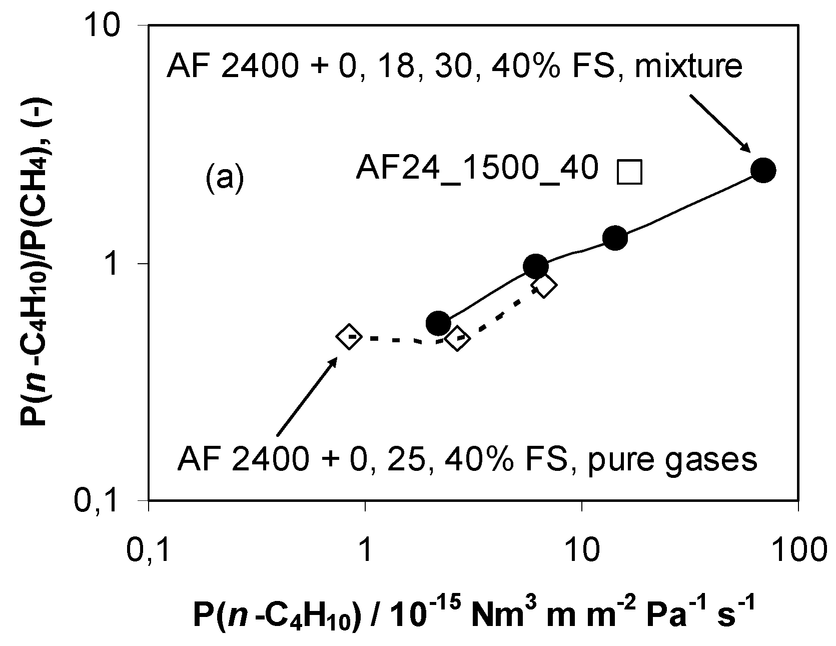
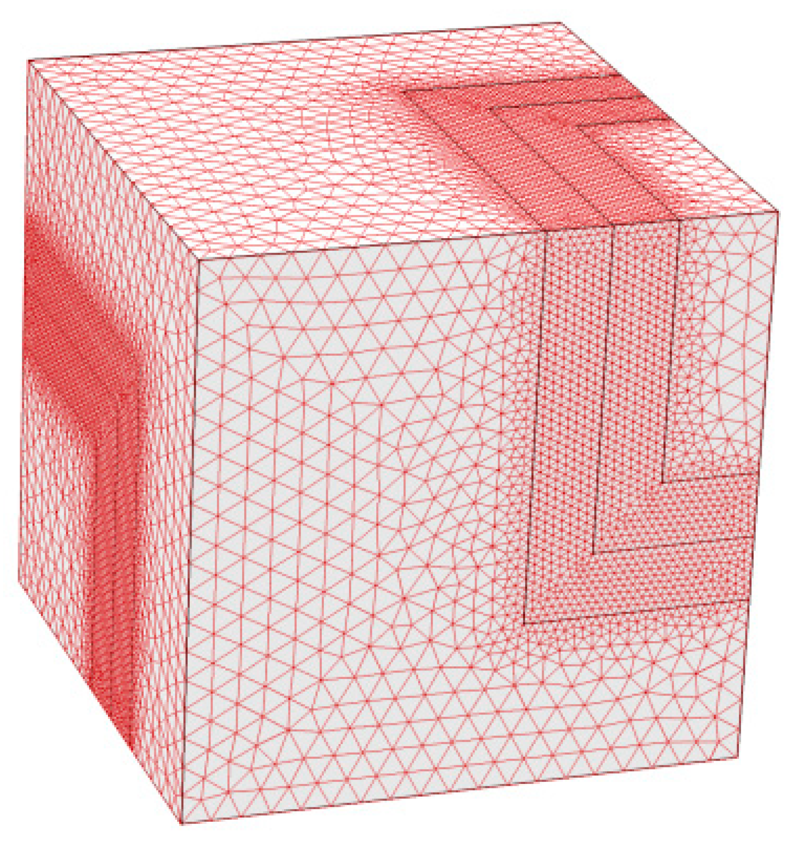
4.1.2. Modelling of the Transport Properties of Teflon AF1600/MFI MMMs
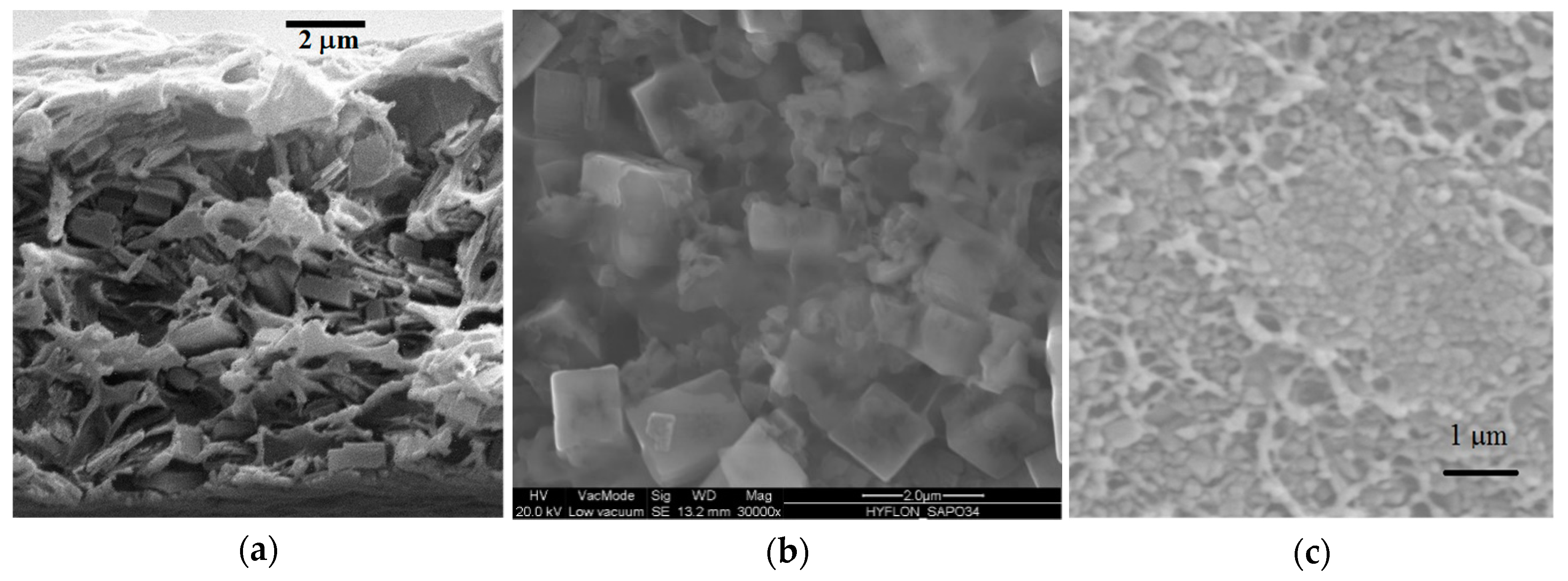
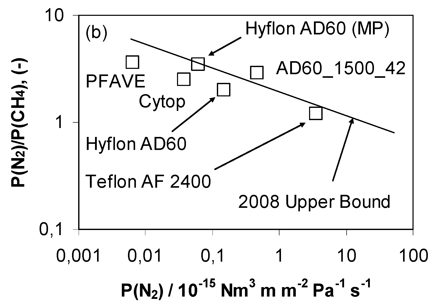
4.2. Hyflon AD60X/SAPO-34 MMMs
4.2.1. Derivation of the Gas Permeability of SAPO-34
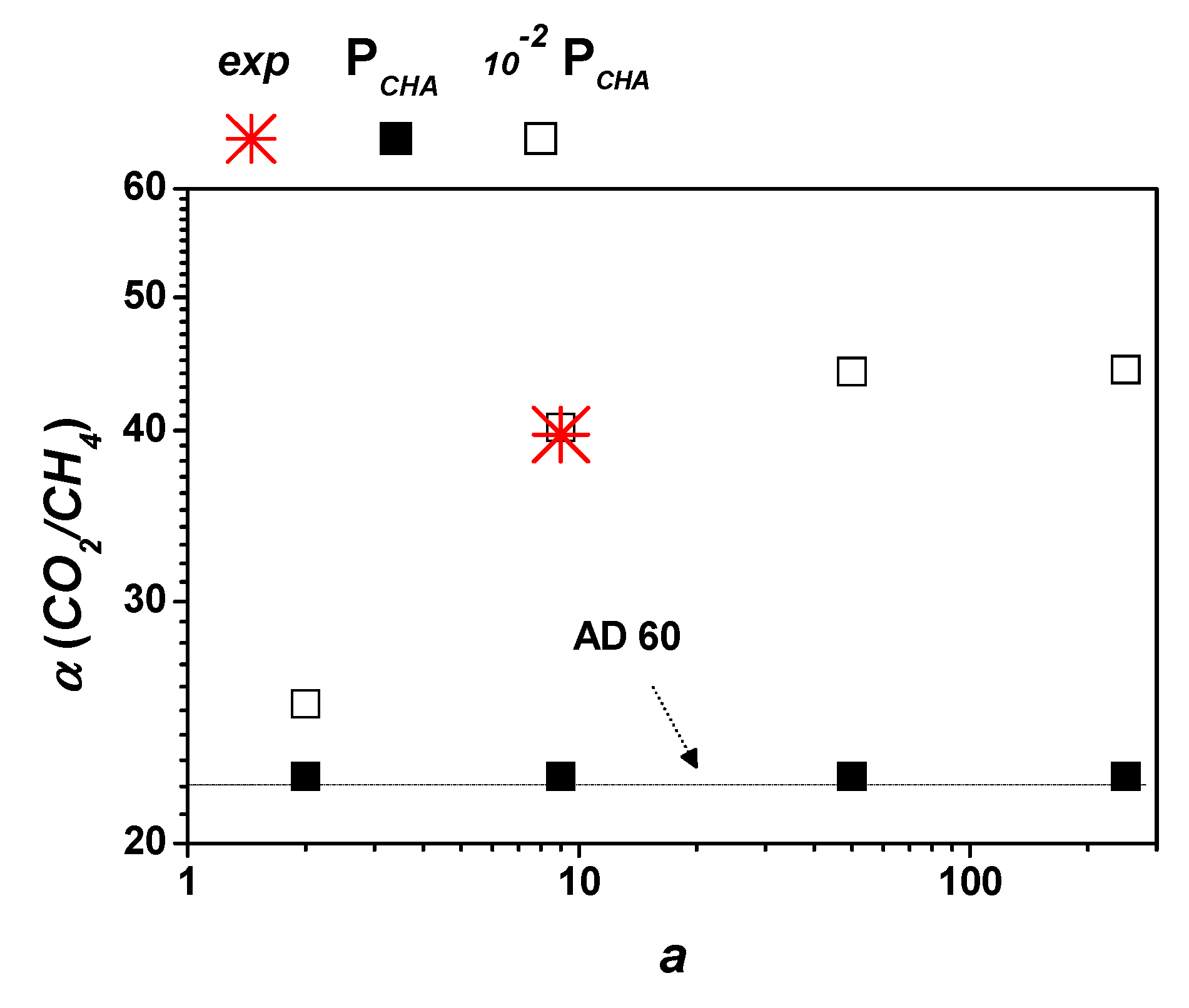
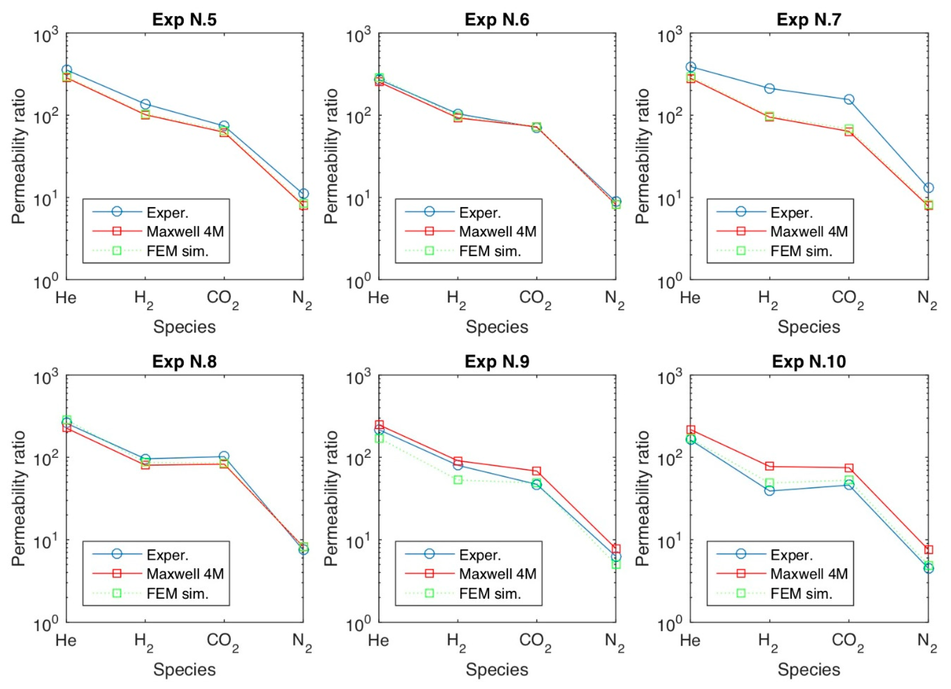
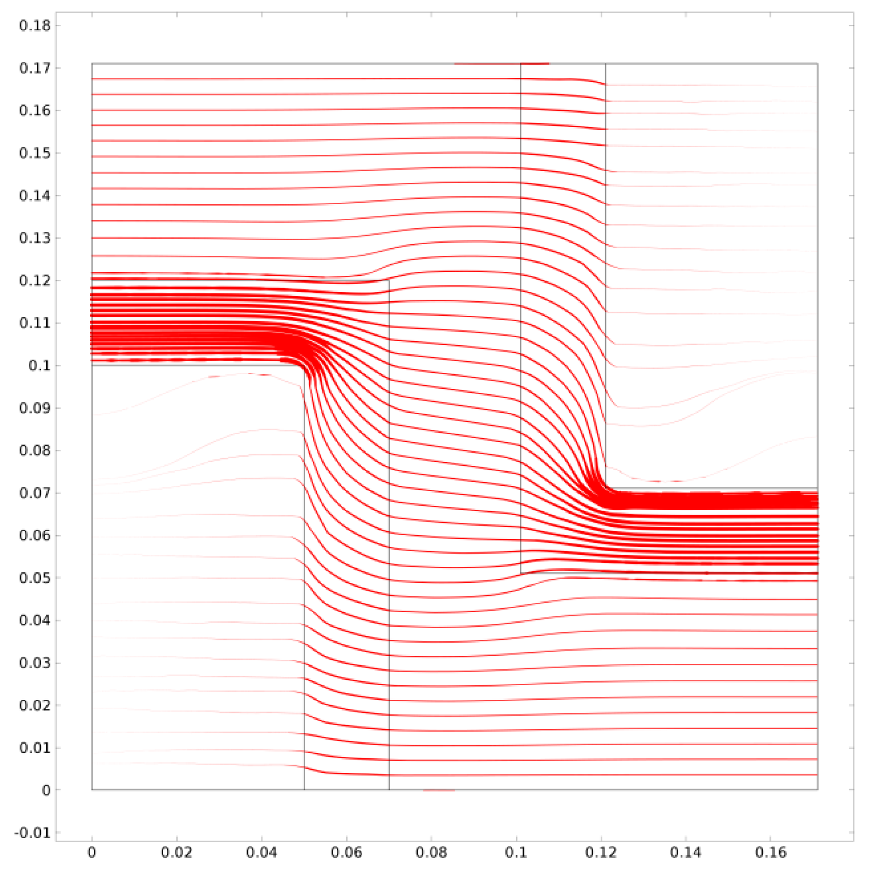
4.2.2. Modelling of the Transport Properties of Hyflon AD60X/SAPO-34 MMMs
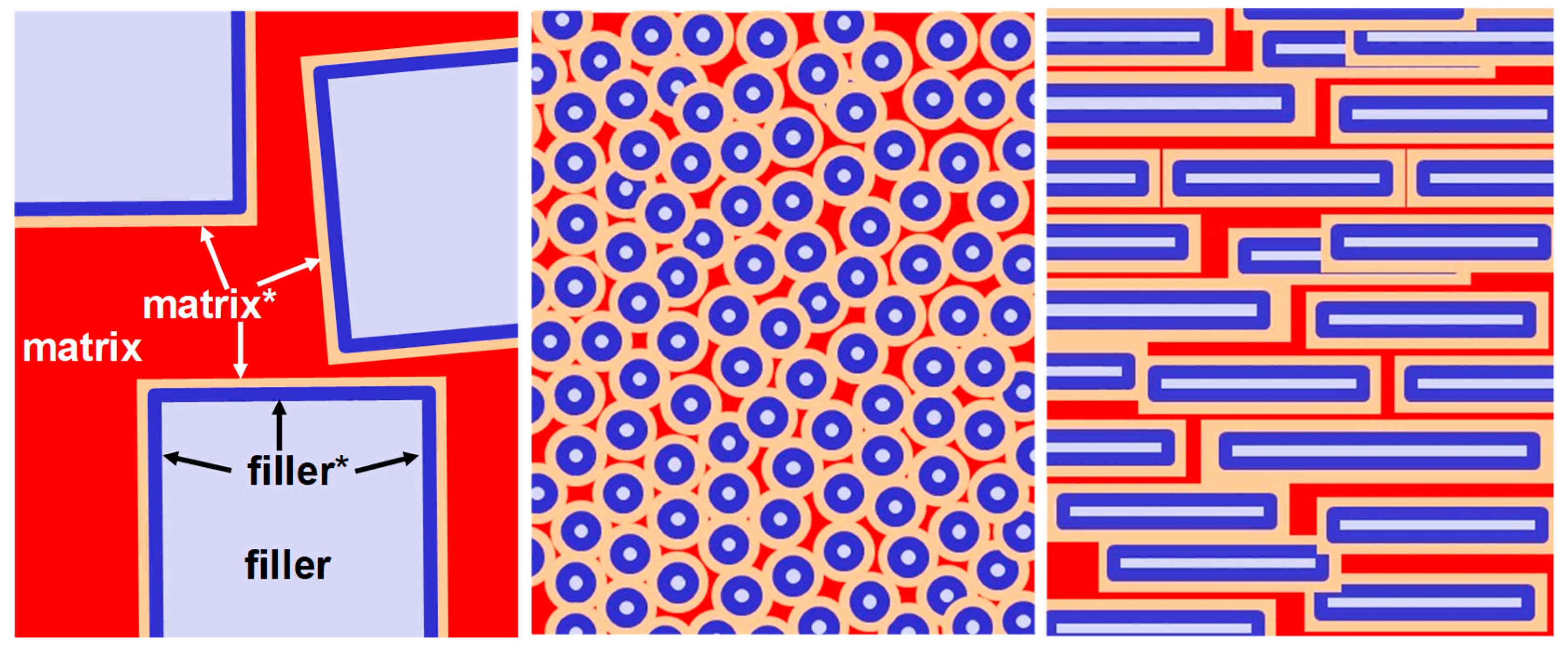
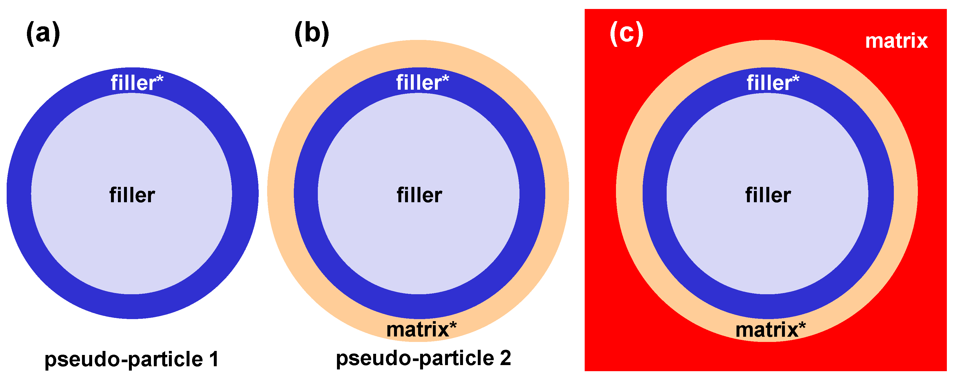
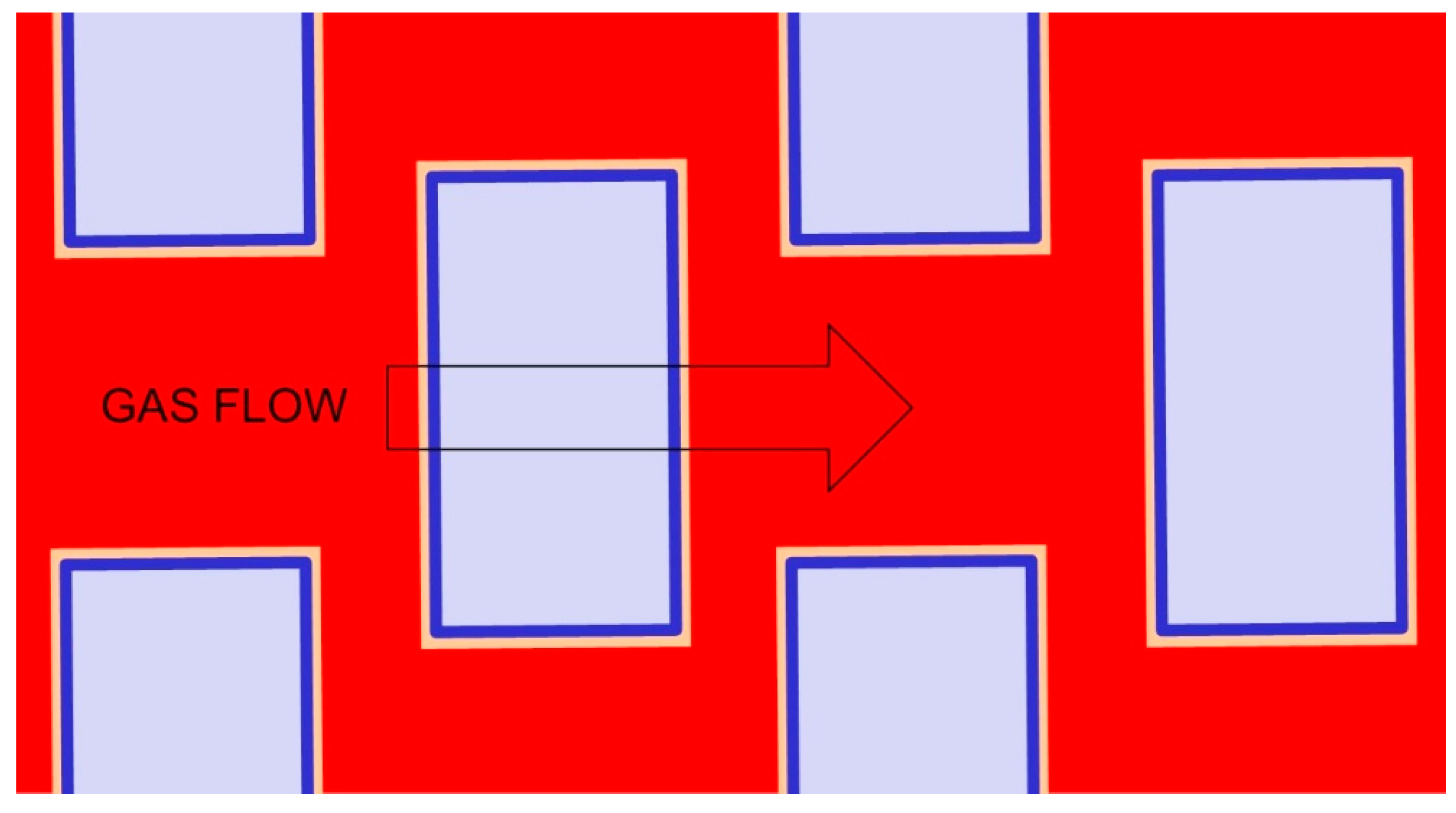
4.3. Remarks and Perspectives on the Modelling of Transport in MMMs
5. Summary and Conclusions
Funding
Conflicts of Interest
List of Symbols and Acronyms
| 4M | four-phase Maxwell model |
| α | permeability selectivity, - |
| αS | solubility selectivity, - |
| αD | diffusion selectivity, - |
| φ | volume fraction, - |
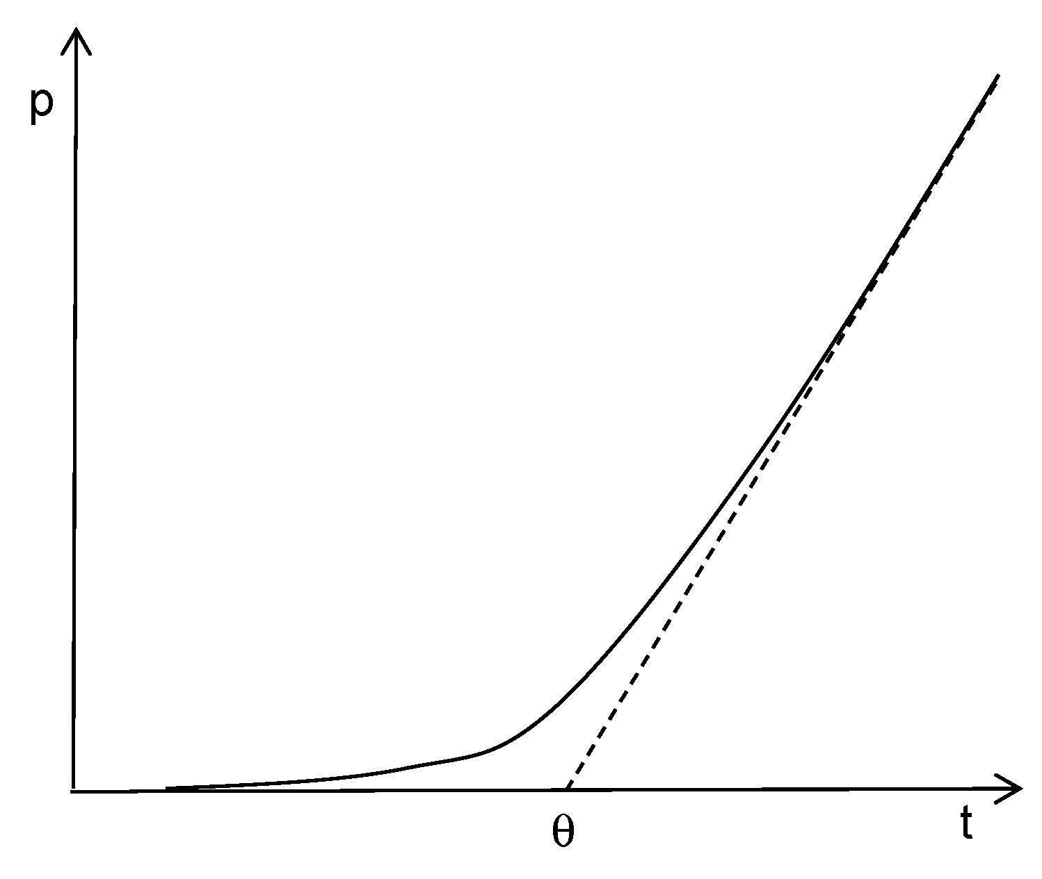
| θ | time-lag, s |
| AR | aspect ratio, - |
| Barrer | permeability unit, 10−10 cm3 (STP) cm cmHg−1·s−1·cm−2 |
| BET | Brunauer, Emmett and Teller method for the determination of the surface area |
| C | concentration, mol m−3 or cm3(STP) cm−3 |
| CHA | framework type code of zeolite chabasite |
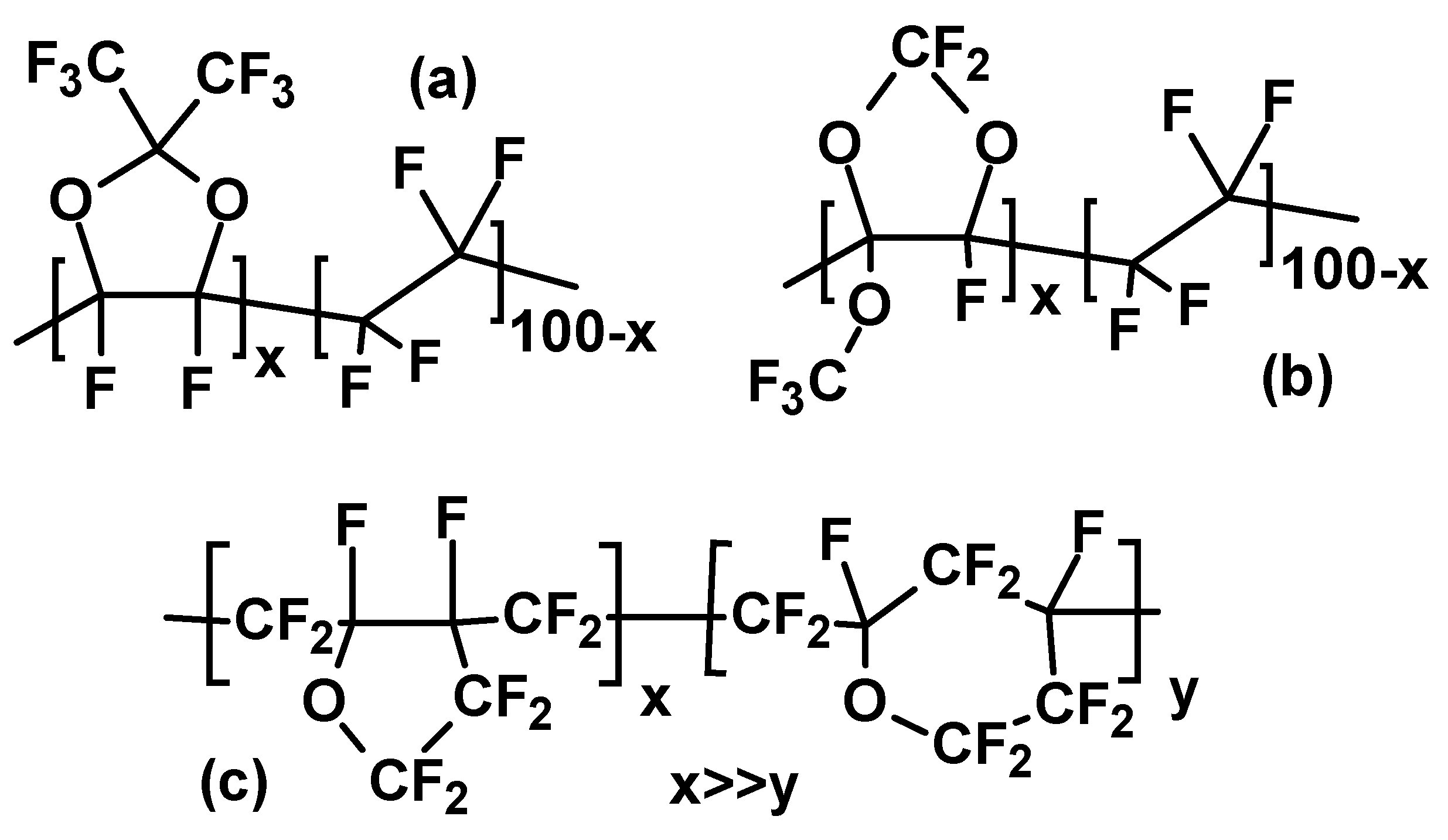
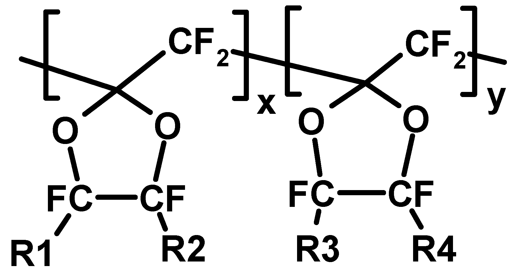
| Cytop® | poly(perfluoro-4-vinyloxy-1-butene) |
| D | diffusivity, m2/s |
| dk | kinetic diameter, Å |
| FEM | finite element numerical modelling |
| FFV | fractional free volume, - |
| Hyflon® AD | co-polymers of tetrafluoroethylene and perfluoro-4-methoxy-1,3-dioxole |
| J | flux, mol/(m2·s) or cm3(STP)/(cm3·s) |
| l | membrane thickness, μm |
| MD | molecular dynamics |
| MFI | framework type code of zeolite ZSM-5 |
| MMM | mixed matrix membrane |
| MOF | metal organic framework |
| Nafion® | copolymers of tetrafluoroethylene and sulfonic acid terminated perfluorovinyl ethers |
| NELF | non-equilibrium lattice fluid |
| NMR | nuclear magnetic resonance |
| p | pressure, Pa |
| P | permeability, Barrer or Nm3·m·m−2·Pa−1·s−1 |
| PF | permeability of the dispersed phase, Barrer or Nm3·m·m−2·Pa−1·s−1 |
| PM | permeability of the continuous phase, Barrer or Nm3·m·m−2·Pa−1·s−1 |
| PMMM | permeability of the MMM, Barrer or Nm3·m·m−2·Pa−1·s−1 |
| PALS | positron annihilation lifetime spectroscopy |
| PFG-NMR | pulsed field gradient NMR |
| S | solubility, mol·m−3·Pa−1 or cm3(STP)·cm−3·Pa−1 |
| Tc | critical temperature, K |
| Tg | glass transition temperature, K |
| PFP | perfluorinated polymer |
| PIM | polymer of intrinsic microporosity |
| SAPO-34 | silicon aluminium phosphate of chasbasite (CHA) structure topology. |
| SEM | scanning electron microscopy |
| Silicalite-1 | pure SiO2 zeolite of ZSM-5 (MFI) structure topology |
| Teflon® | polytetrafluoroethylene |
| Teflon® AF | co-polymer of tetrafluoroethylene and perfluoro-2,2-dimethyl-1,3-dioxole |
| STP | standard temperature and pressure |
References
- Cui, Z.; Drioli, E.; Lee, Y.-M. Recent Progress in Fluoropolymer Membranes. Progr. Polym. Sci. 2014, 39, 164–198. [Google Scholar] [CrossRef]
- Marzouk, S.A.M.; Al-Marzouqi, M.H.; Teramoto, M.; Abdullatif, N.; Ismail, Z.M. Simultaneous Removal of CO2 and H2S from Pressurized CO2-H2S-CH4 Gas Mixture Using Hollow Fiber Membrane Contactors. Sep. Purif. Technol. 2012, 86, 88–97. [Google Scholar] [CrossRef]
- Feng, S.; Zhong, Z.; Wang, Y.; Xing, W.; Drioli, E. Progress and Perspectives in PTFE Membranes: Preparation, Modification and Application. J. Membr. Sci. 2018, 549, 332–349. [Google Scholar] [CrossRef]
- Buonomenna, M.G.; Golemme, G.; De Santo, M.P.; Drioli, E. Direct Oxidation of Cyclohexene with Inert Polymeric Membrane Reactor. Org. Process Res. Dev. 2010, 14, 252–258. [Google Scholar] [CrossRef]
- Scholes, C.; Stevens, G.; Kentish, S. Membrane Gas Separation Applications in Natural Gas Processing. Fuel 2012, 96, 15–28. [Google Scholar] [CrossRef]
- Merkel, T.C.; Pinnau, I.; Prabhakar, R.; Freeman, B.D. Gas and Vapor Transport Properties of Perfluoropolymers. In Materials Science of Membranes for Gas and Vapor Separation; Yampolskii, Y.P., Pinnau, I., Freeman, B.D., Eds.; John Wiley & Sons: Chichester, UK, 2006; Chapter 9; pp. 251–270. [Google Scholar]
- Golemme, G. Perfluoropolymer Membranes for Separations and Electrochemical Processes. In Advanced Materials for Membrane Preparation; Buonomenna, M.G., Golemme, G., Eds.; Bentham Science: Sharjah, UAE, 2012; Chapter 9; pp. 106–124. [Google Scholar]
- Arcella, V.; Merlo, L.; Pieri, R.; Toniolo, P.; Triulzi, F.; Apostolo, M. Fluoropolymers for Sustainable Energy. In Handbook of Fluoropolymer Science and Technology; Smith, D.W., Jr., Iacono, S.T., Iyer, S.S., Eds.; John Wiley & Sons: Hoboken, NJ, USA, 2014; Chapter 17; pp. 393–412. [Google Scholar]
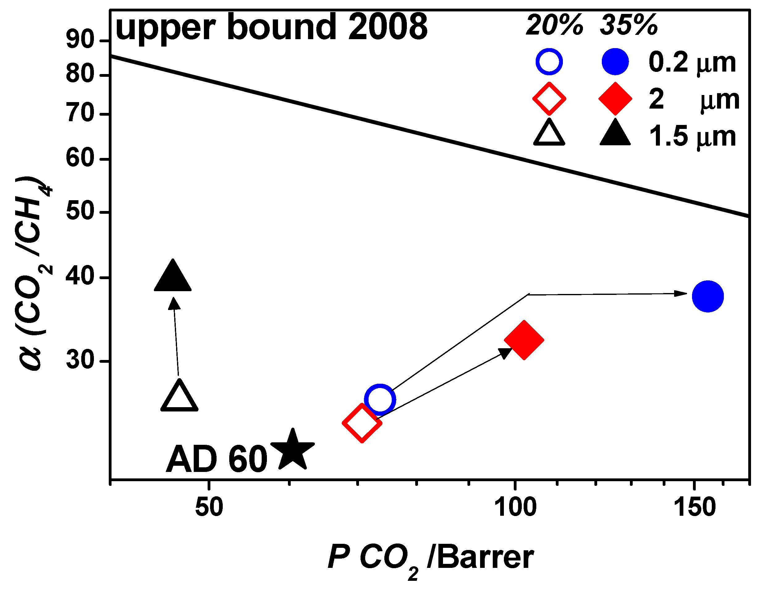
- Robeson, L.M. The Upper Bound Revisited. J. Membr. Sci. 2008, 320, 390–400. [Google Scholar] [CrossRef]
- Plunkett, R.J. Tetrafluoroethylene Polymers. U.S. Patent 2230654, 1941. [Google Scholar]
- Nakamura, M.; Sugiyama, N.; Etoh, Y.; Aosaki, K.; Endo, J. Development of Perfluoro Transparent Resins Obtained by Radical Cyclopolymerization for Leading Edge Electronic and Optical Applications. Nippon Kagaku Kaishi 2001, 12, 659–668. [Google Scholar] [CrossRef]
- Van Krevelen, D.V.; Nijenhuis, K. Properties of Polymers, 4th ed.; Elsevier: Amsterdam, The Netherlands, 2009. [Google Scholar]
- Hansen, C.M. Hansen Solubility Parameters: A User’s Handbook; CRC Press: Boca Raton, FL, USA, 2007. [Google Scholar]
- Resnick, P.R.; Buck, W.H. Teflon® AF Amorphous Fluoropolymers. In Modern Fluoropolymers. High Performance Polymers for Diverse Applications; Scheirs, J., Ed.; Wiley: Chichester, UK, 1997; p. 397. [Google Scholar]
- Tokarev, A.V.; Bondarenko, G.N.; Yampol’skii, Y.P. Chain Structure and Stiffness of Teflon AF Glassy Amorphous Fluoropolymers. Polym. Sci. (Vysokomol. Soedin.) Ser. A 2007, 49, 909–920. [Google Scholar] [CrossRef]
- Alentiev, A.Y.; Yampolskii, Y.P.; Shantarovich, V.P.; Nemser, S.M.; Platé, N.A. High Transport Parameters and Free Volume of Perfluorodioxole Copolymers. J. Membr. Sci. 1997, 126, 123–132. [Google Scholar] [CrossRef]
- Golemme, G.; Nagy, J.B.; Fonseca, A.; Algieri, C.; Yampolskii, Y.P. 129Xe NMR Study of Free Volume in Amorphous Perfluorinated Polymers: Comparsion with Other Methods. Polymer 2003, 44, 5039–5045. [Google Scholar] [CrossRef]
- Bondar, V.I.; Freeman, B.D.; Yampol’skii, Y.P. Sorption of Gases and Vapors in an Amorphous Glassy Perfluorodioxole Copolymer. Macromolecules 1999, 32, 6163–6171. [Google Scholar] [CrossRef]
- Dlubek, G.; Pionteck, J.; Rätzke, K.; Kruse, J.; Faupel, F. Temperature Dependence of the Free Volume in Amorphous Teflon AF1600 and AF2400: A Pressure-Volume-Temperature and Positron Lifetime Study. Macromolecules 2008, 41, 6125–6133. [Google Scholar] [CrossRef]
- Wijmans, J.G.; Baker, R.W. The Solution-Diffusion Model: A Review. J. Membr. Sci. 1995, 107, 1–21. [Google Scholar] [CrossRef]
- Wijmans, J.G.; Baker, R.W. The Solution-Diffusion Model: A Unified Approach to Membrane Permeation. In Materials Science of Membranes for Gas and Vapor Separation; Yampolskii, Y.P., Pinnau, I., Freeman, B.D., Eds.; John Wiley & Sons: Chichester, UK, 2006; Chapter 5; pp. 159–189. [Google Scholar]
- Nagai, K.; Masuda, T.; Nakagawa, T.; Freeman, B.D.; Pinnau, I. Poly[1-(trimethylsilyl)-1-propyne) and Related Polymers: Synthesis, Properties and other Functions. Prog. Polym. Sci. 2011, 26, 721–798. [Google Scholar] [CrossRef]
- Morisato, A.; Pinnau, I. Synthesis and Gas Permeation Properties of Poly(4-methyl-2-pentyne). J. Membr. Sci. 1996, 121, 243–250. [Google Scholar] [CrossRef]
- McKeown, N.B.; Budd, P.M.; Msayib, K.J.; Ghanem, B.S.; Kingston, H.J.; Tattershall, C.E.; Makhseed, S.; Reynolds, K.J.; Fritsch, D. Polymers of Intrinsic Microporosity (PIMs): Bridging the Void between Microporous and Polymeric Materials. Chem. Eur. J. 2005, 11, 2610–2620. [Google Scholar] [CrossRef] [PubMed]
- Breck, D.W. Zeolite Molecular Sieves: Structure, Chemistry, and Use; J. Wiley and Sons: New York, NY, USA, 1974. [Google Scholar]
- National Institute of Standards and Technology. Available online: https://webbook.nist.gov/chemistry/name-ser/ (accessed on 15 October 2018).
- Belov, N.A.; Alentiev, A.Y.; Ronova, I.A.; Sinitsyna, O.V.; Nikolaev, A.Y.; Zharov, A.A. Microstructure Relaxation Process of Polyhexafluoropropylene after Swelling in Supercritical Carbon Dioxide. J. Appl. Polym. Sci. 2016, 133, 43105. [Google Scholar] [CrossRef]
- Belov, N.; Nikiforov, R.; Polunin, E.; Pogodina, Y.; Zavarzin, I.; Shantarovich, V.; Yampolskii, Y. Gas Permeation, Diffusion, Sorption and Free Volume of Poly(2-trifluoromethyl-2-pentafluoroethyl-1,3-perfluorodioxole). J. Membr. Sci. 2018, 565, 112–118. [Google Scholar] [CrossRef]
- Okamoto, Y.; Du, Q.; Koike, K.; Mikeš, F.; Merkel, T.C.; He, Z.; Zhang, H.; Koike, Y. New Amorphous Perfluoro Polymers: Perfluorodioxolane Polymers for Use as Plastic Optical Fibers and Gas Separation Membranes. Polym. Adv. Technol. 2016, 27, 33–41. [Google Scholar] [CrossRef]
- Fang, M.; He, Z.; Merkel, T.C.; Okamoto, Y. High-performance Perfluorodioxolane Copolymer Membranes for Gas Separation with Tailored Selectivity Enhancement. J. Mater. Chem. A 2018, 6, 652–658. [Google Scholar] [CrossRef]
- Okamoto, Y.; Zhang, H.; Mikeš, F.; Koike, Y.; He, Z.; Merkel, T.C. New Perfluoro-dioxolane-based Membranes for Gas Separations. J. Membr. Sci. 2014, 471, 412–419. [Google Scholar] [CrossRef]
- Baker, R.W.; Lokhandwala, K. Natural Gas Processing with Membranes: An Overview. Ind. Eng. Chem. Res. 2008, 47, 2109–2121. [Google Scholar] [CrossRef]
- Buonomenna, M.G.; Yave, W.; Golemme, G. Some Approaches for High Performance Polymer Based Membranes for Gas Separation: Block Copolymers, Carbon Molecular Sieves and Mixed Matrix Membranes. RSC Adv. 2012, 2, 10745–10773. [Google Scholar] [CrossRef]
- Chuah, C.Y.; Goh, K.; Yang, Y.; Gong, H.; Li, W.; Karahan, H.E.; Guiver, M.D.; Wang, R.; Bae, T.-H. Harnessing Filler Materials for Enhancing Biogas Separation Membranes. Chem. Rev. 2018, 118, 8655–8769. [Google Scholar] [CrossRef] [PubMed]
- Moore, T.T.; Koros, W.J. Non-Ideal Effects in Organic–Inorganic Materials for Gas Separation Membranes. J. Mol. Struct. 2005, 739, 87–98. [Google Scholar] [CrossRef]
- Kalantzopoulos, G.; Policicchio, A.; Maccallini, E.; Krkljus, I.; Ciuchi, F.; Hirscher, M.; Agostino, R.G.; Golemme, G. Resistance to the Transport of H2 through the External Surface of As-made and Modified Silicalite-1 (MFI). Microporous Mesoporous Mater. 2016, 220, 290–297. [Google Scholar] [CrossRef]
- Vankelecom, I.F.J.; Van den Broeck, S.; Merckx, E.; Geerts, H.; Grobet, P.; Uytterhoeven, J.B. Silylation to Improve Incorporation of Zeolites in Polyimide Films. J. Phys. Chem. 1996, 100, 3753–3758. [Google Scholar] [CrossRef]
- Fernández-Barquín, A.; Casado-Coterillo, C.; Palomino, M.; Valencia, S.; Irabien, A. LTA/Poly(1-trimethylsilyl-1-propyne) Mixed-Matrix Membranes for High-Temperature CO2/N2 Separation. Chem. Eng. Technol. 2015, 38, 658–666. [Google Scholar] [CrossRef]
- Golemme, G.; Bruno, A.; Manes, R.; Muoio, D. Preparation and Properties of Superglassy Polymers—Zeolite Mixed Matrix Membranes. Desalination 2006, 200, 440–442. [Google Scholar] [CrossRef]
- Golemme, G.; Policicchio, A.; Sardella, E.; De Luca, G.; Russo, B.; Liguori, P.F.; Melicchio, A.; Agostino, R.G. Surface Modification of Molecular Sieve Fillers for Mixed Matrix Membranes. Colloid Surf. A Physicochem. Eng. Asp. 2018, 538, 333–342. [Google Scholar] [CrossRef]
- Smirnov, K.S. A Molecular Dynamics Study of the Interaction of Water with the External Surface of Silicalite-1. Phys. Chem. Chem. Phys. 2017, 19, 2950–2960. [Google Scholar] [CrossRef]
- Wang, H.T.; Holmberg, B.T.; Yan, Y.S. Homogeneous Polymer-Zeolite Nanocomposite Membranes by Incorporating Dispersible Template-removed Zeolite Nanocrystals. J. Mater. Chem. 2002, 12, 3640–3643. [Google Scholar] [CrossRef]
- Santaniello, A.; Golemme, G. Interfacial Control in Perfluoropolymer Mixed Matrix Membranes for Natural Gas Sweetening. J. Ind. Eng. Chem. 2018, 60, 169–176. [Google Scholar] [CrossRef]
- Di Maio, F.P.; Santaniello, A.; Di Renzo, A.; Golemme, G. Description of Gas Transport in Perfluoropolymer/SAPO-34 Mixed Matrix Membranes Using Four-Resistance Model. Sep. Purif. Technol. 2017, 185, 160–174. [Google Scholar] [CrossRef]
- Golemme, G.; Jansen, J.C.; Muoio, D.; Bruno, A.; Manes, R.; Buonomenna, M.G.; Choi, J.; Tsapatsis, M. Glassy Perfluoropolymer—Zeolite Hybrid Membranes for Gas Separations. In Membrane Gas Separation; Yampolskii, Y.P., Freeman, B.D., Eds.; John Wiley & Sons: Chichester, UK, 2010; Chapter 6; pp. 113–124. [Google Scholar] [CrossRef]
- Flanigen, E.M.; Bennett, J.M.; Grose, R.W.; Cohen, J.P.; Patton, R.L.; Kirchner, R.M.; Smith, J.V. Silicalite, a New Hydrophobic Crystalline Silica Molecular Sieve. Nature 1978, 271, 512–516. [Google Scholar] [CrossRef]
- Kärger, J.; Ruthven, D.M.; Theodorou, D.N. Diffusion in Nanoporous Materials; Wiley VCH: Weinheim, Germany, 2012; ISBN 9783527310241. [Google Scholar]
- Merkel, T.C.; He, Z.; Pinnau, I.; Freeman, B.D.; Meakin, P.; Hill, A.J. Sorption and Transport in Poly(2,2-bis(trifluoromethyl)-4,5-difluoro-1,3-dioxole-co-tetrafluoroethylene) Containing Nanoscale Fumed Silica. Macromolecules 2003, 36, 8406–8414. [Google Scholar] [CrossRef]
- Merkel, T.C.; He, Z.; Pinnau, I.; Freeman, B.D.; Meakin, P.; Hill, A.J. Effect of Nanoparticles on Gas Sorption and Transport in Poly(1-trimethylsilyl-1-propyne). Macromolecules 2003, 36, 6844–6855. [Google Scholar] [CrossRef]
- Merkel, T.C.; Freeman, B.D.; Spontak, R.J.; He, Z.; Pinnau, I.; Meakin, P.; Hill, A.J. Ultrapermeable, Reverse-Selective Nanocomposite Membranes. Science 2002, 296, 519–522. [Google Scholar] [CrossRef]
- De Angelis, M.G.; Sarti, G.C. Solubility and Diffusivity of Gases in Mixed Matrix Membranes containing Fumed Silica: Correlations and Predictions Based on the NELF Model. Ind. Eng. Chem. Res. 2008, 47, 5214–5226. [Google Scholar] [CrossRef]
- Ferrari, M.C.; Galizia, M.; De Angelis, M.G.; Sarti, G.C. Gas and Vapor Transport in Mixed Matrix Membranes Based on Amorphous Teflon AF1600 and AF2400 and Fumed Silica. Ind. Eng. Chem. Res. 2010, 49, 11920–11935. [Google Scholar] [CrossRef]
- Krishna, R. Multi-scale Modeling Strategy for Separation of Alkane Mixtures using Zeolites. Comput. Aided Chem. Eng. 2002, 10, 109–114. [Google Scholar]
- Maxwell, J.C. A Treatise on Electricity and Magnetism; Dover Publication: New York, NY, USA, 1954. [Google Scholar]
- Yu, M.; Noble, R.D.; Falconer, J.L. Zeolite Membranes: Microstructure Characterization and Permeation Mechanisms. Acc. Chem. Res. 2011, 44, 1196–1206. [Google Scholar] [CrossRef] [PubMed]
- Ahunbay, M.G.; Elliott, J.R., Jr.; Talu, O. The Diffusion Process of Methane through a Silicalite Single Crystal Membrane. J. Phys. Chem. B 2002, 106, 5163–5168. [Google Scholar] [CrossRef]
- Ahunbay, M.G.; Elliott, J.R., Jr.; Talu, O. Surface Resistance to Permeation through the Silicalite Single Crystal Membrane: Variation with Permeant. J. Phys. Chem. B 2004, 108, 7801–7808. [Google Scholar] [CrossRef]
- Newsome, D.A.; Sholl, D.S. Atomically detailed simulations of surface resistances to transport of CH4, CF4, and C2H6 through silicalite membranes. Microporous Mesoporous Mater. 2008, 107, 286–295. [Google Scholar] [CrossRef]
- Combariza, A.F.; Sastre, G. Influence of Zeolite Surface in the Sorption of Methane from Molecular Dynamics. J. Phys. Chem. C 2011, 115, 13751–13758. [Google Scholar] [CrossRef]
- Stavitski, E.; Drury, M.R.; de Winter, D.A.M.; Kox, M.H.F.; Weckhuysen, B.M. Intergrowth Structure of Zeolite Crystals and Pore Orientation of Individual Subunits Revealed by Electron Backscatter Diffraction/Focused Ion Beam Experiments. Angew. Chem. Int. Ed. 2008, 47, 5637–5640. [Google Scholar] [CrossRef] [PubMed] [Green Version]
- Chmelik, C.; Kortunov, P.; Vasenkov, S.; Kärger, J. Imaging of Transient Guest Profiles in Nanoporous Host Materials: A New Experimental Technique to Study Intra-Crystalline Diffusion. Adsorption 2005, 11, 455–460. [Google Scholar] [CrossRef]
- Karwacki, L.; van der Bij, H.E.; Kornatowski, J.; Cubillas, P.; Drury, M.R.; de Winter, D.A.M.; Anderson, M.W.; Weckhuysen, B.M. Unified Internal Architecture and Surface Barriers for Molecular Diffusion of Microporous Crystalline Aluminophosphates. Angew. Chem. Int. Ed. 2010, 49, 6790–6794. [Google Scholar] [CrossRef]
- Hibbe, F.; Chmelik, C.; Heinke, L.; Pramanik, S.; Li, J.; Ruthven, D.M.; Tzoulaki, D.; Kärger, J. The Nature of Surface Barriers on Nanoporous Solids Explored by Microimaging of Transient Guest Distributions. J. Am. Chem. Soc. 2011, 133, 2804–2807. [Google Scholar] [CrossRef] [PubMed]
- Cousin Saint Remi, J.; Lauerer, A.; Chmelik, C.; Vandendael, I.; Terryn, H.; Baron, G.V.; Denayer, J.F.M.; Kärger, J. The Role of Crystal Diversity in Understanding Mass Transfer in Nanoporous Materials. Nat. Mater. 2015, 15, 401–406. [Google Scholar] [CrossRef] [PubMed]
- Karwacki, L.; Kox, M.H.F.; de Winter, D.A.M.; Drury, M.R.; Meeldijk, J.D.; Stavitski, E.; Schmidt, W.; Mertens, M.; Cubillas, P.; John, N.; et al. Morphology-Dependent Zeolite Intergrowth Structures Leading to Distinct Internal and Outer-Surface Molecular Diffusion Barriers. Nat. Mater. 2009, 8, 959–965. [Google Scholar] [CrossRef] [PubMed]
- Fasano, M.; Humplik, T.; Bevilacqua, A.; Tsapatsis, M.; Chiavazzo, E.; Wang, E.N.; Asinari, P. Interplay between Hydrophilicity and Surface Barriers on Water Transport in Zeolite Membranes. Nat. Commun. 2016, 7, 12762. [Google Scholar] [CrossRef] [PubMed]
- Kortunov, P.; Vasenkov, S.; Chmelik, C.; Kärger, J.; Ruthven, D.M.; Włoch, J. Influence of Defects on the External Crystal Surface on Molecular Uptake into MFI-Type Zeolites. Chem. Mater. 2004, 16, 3552–3558. [Google Scholar] [CrossRef]
- Brabec, L.; Kocirik, M. Silicalite-1 Crystals Etched with Hydrofluoric Acid Dissolved in Water or Acetone. J. Phys. Chem. C 2010, 114, 13685–13694. [Google Scholar] [CrossRef]
- Tzoulaki, D.; Schmidt, W.; Wilczok, U.; Kärger, J. Formation of Surface Barriers on Silicalite-1 Crystal Fragments by Residual Water Vapour as Probed with Isobutane by Interference Microscopy. Microporous Mesoporous Mater. 2008, 110, 72–76. [Google Scholar] [CrossRef]
- Texeira, A.R.; Chang, C.C.; Coogan, T.; Kendall, R.; Fan, W.; Dauenhauer, P.J. Dominance of Surface Barriers in Molecular Transport through Silicalite-1. J. Phys. Chem. C 2013, 117, 25545–25555. [Google Scholar] [CrossRef]
- Chisholm, N.O.; Funke, H.H.; Noble, R.D.; Falconer, J.L. Carbon Dioxide/Alkane Separations in a SSZ-13 Membrane. J. Membr. Sci. 2018, 568, 17–21. [Google Scholar] [CrossRef]
- Krishna, R. Diffusion of Binary Mixtures in Zeolites: Molecular Dynamics Simulations Versus Maxwell–Stefan Theory. Chem. Phys. Lett. 2000, 326, 477–484. [Google Scholar] [CrossRef]
- Chempath, S.; Krishna, R.; Snurr, R.Q. Nonequilibrium Molecular Dynamics Simulations of Diffusion of Binary Mixtures Containing Short N-Alkanes in Faujasite. J. Phys. Chem. B 2004, 108, 13481–13491. [Google Scholar] [CrossRef]
- Krishna, R.; Van Baten, J. Unified Maxwell-Stefan Description of Binary Mixture Diffusion in Micro- and Meso-Porous Materials. Chem. Eng. Sci. 2009, 64, 3159–3178. [Google Scholar] [CrossRef]
- Krishna, R. The Maxwell—Stefan Description of Mixture Diffusion in Nanoporous Crystalline Materials. Microporous Mesoporous Mater. 2014, 185, 30–50. [Google Scholar] [CrossRef]
- Krishna, R. Methodologies for Screening and Selection of Crystalline Microporous Materials in Mixture Separations. Sep. Purif. Technol. 2018, 194, 281–300. [Google Scholar] [CrossRef]
- Nijhuis, T.A.; van den Broeke, L.J.P.; Linders, M.J.G.; van de Graaf, J.M.; Kapteijn, F.; Makkee, M.; Moulijn, J.A. Measurement and Modeling of the Transient Adsorption, Desorption and Diffusion Processes in Microporous Materials. Chem. Eng. Sci. 1999, 54, 4423–4436. [Google Scholar] [CrossRef]
- Sun, M.S.; Shah, D.B.; Xu, H.H.; Talu, O. Adsorption Equilibria of C1 to C4 Alkanes, CO2, and SF6 on Silicalite. J. Phys. Chem. B 1998, 102, 1466–1473. [Google Scholar] [CrossRef]
- Rutherford, S.W.; Do, D.D. Review of Time Lag Permeation Technique as a Method for Characterisation of Porous Media and Membranes. Adsorption 1997, 3, 283–312. [Google Scholar] [CrossRef]
- Paul, D.R. Effect of Immobilizating Adsorption on the Diffusion Time-Lag. J. Polym. Sci. Part A-2 1969, 27, 1811–1818. [Google Scholar] [CrossRef]
- Şen, D.; Kalıpçılar, H.; Yilmaz, L. Development of Polycarbonate Based Zeolite 4A Filled Mixed Matrix Gas Separation Membranes. J. Membr. Sci. 2007, 303, 194–203. [Google Scholar] [CrossRef]
- Wang, L.; Corriou, J.P.; Castel, C.; Favre, E. Transport of Gases in Glassy Polymers under Transient Conditions: Limit-Behavior Investigations in Dual-Mode Sorption Theory. Ind. Eng. Chem. Res. 2013, 52, 1089–1101. [Google Scholar] [CrossRef]
- Paul, D.R.; Kemp, D.R. The Diffusion Time Lag in Polymer Membranes Containing Adsorptive Fillers. J. Polym. Sci. Polym. Symp. 1973, 41, 79–93. [Google Scholar] [CrossRef]
- Paul, D.R.; Koros, W.J. Effect of Partially Immobilizating Sorption on Permeability and the Diffusion Time Lag. J. Polym. Sci. Part B Polym. Phys. 1976, 14, 675–685. [Google Scholar] [CrossRef]
- Lok, B.M.; Messina, C.A.; Patton, R.L.; Gajek, R.T.; Cannan, T.R.; Flanigen, E.M. Silicoaluminophosphate Molecular Sieves: Another New Class of Microporous Crystalline Inorganic Solids. J. Am. Chem. Soc. 1984, 106, 6092–6093. [Google Scholar] [CrossRef]
- Funke, H.H.; Chen, M.Z.; Prakash, A.N.; Falconer, J.L.; Noble, R.D. Separating Molecules by Size in SAPO-34 Membranes. J. Membr. Sci. 2014, 456, 185–191. [Google Scholar] [CrossRef]
- Krishna, R.; van Baten, J.M. In Silico Screening of Zeolite Membranes for CO2 Capture. J. Membr. Sci. 2010, 360, 323–333. [Google Scholar] [CrossRef]
- Krishna, R.; van Baten, J.M. Segregation Effects in Adsorption of CO2 Containing Mixtures and Their Consequences for Separation Selectivities in Cage-Type Zeolites. Sep. Purif. Technol. 2008, 61, 414–423. [Google Scholar] [CrossRef]
- Zong, Z.; Feng, X.; Huang, Y.; Song, Z.; Zhou, R.; Zhou, S.J.; Carreon, M.A.; Yu, M.; Li, S. Highly Permeable N2/CH4 Separation SAPO-34 Membranes Synthesized by Diluted Gels and Increased Crystallization Temperature. Microporous Mesoporous Mater. 2016, 224, 36–42. [Google Scholar] [CrossRef]
- Krishna, R.; van Baten, J.M. Insights into Diffusion of Gases in Zeolites Gained from Molecular Dynamics Simulations. Microporous Mesoporous Mater. 2008, 109, 91–108. [Google Scholar] [CrossRef]
- Cussler, E.L. Membranes Containing Selective Flakes. J. Membr. Sci. 1990, 52, 275–288. [Google Scholar] [CrossRef]
- Sheffel, J.A.; Tsapatsis, M. A Model for the Performance of Microporous Mixed Matrix Membranes with Oriented Selective Flakes. J. Membr. Sci. 2007, 295, 50–70. [Google Scholar] [CrossRef]
- Sheffel, J.A.; Tsapatsis, M. A Semi-Empirical Approach for Predicting the Performance of Mixed Matrix Membranes Containing Selective Flakes. J. Membr. Sci. 2009, 326, 595–607. [Google Scholar] [CrossRef]
- Mahajan, R.; Koros, W.J. Mixed Matrix Membrane Materials with Glassy Polymers. Part 1. Polym. Eng. Sci. 2002, 42, 1420–1431. [Google Scholar] [CrossRef]
- Ward, J.K.; Koros, W.J. Crosslinkable Mixed Matrix Membranes with Surface Modified Molecular Sieves for Natural Gas Purification: I. Preparation and Experimental Results. J. Membr. Sci. 2011, 377, 75–81. [Google Scholar] [CrossRef]
- Dutta, R.C.; Bhatia, S.K. Interfacial Barriers to Gas Transport in Zeolites: Distinguishing Internal and External Resistances. Phys. Chem. Chem. Phys. 2018, 20, 26386–26395. [Google Scholar] [CrossRef] [PubMed]
- COMSOL, A.B. COMSOL Multiphysics. User’s Guide; COMSOL A.B.: Stockholm, Sweden, 2011. [Google Scholar]
- Jansen, J.; Macchione, M.; Drioli, E. On the Unusual Solvent Retention and the Effect on the Gas Transport in Perfluorinated Hyflon AD® Membranes. J. Membr. Sci. 2007, 287, 132–137. [Google Scholar] [CrossRef]
- Yampolskii, Y.; Shantarovich, V. Positron Annihilation Lifetime Spectroscopy and Other Methods for Free Volume Evaluation in Polymers. In Materials Science of Membranes for Gas and Vapor Separation; Yampolskii, Y.P., Pinnau, I., Freeman, B.D., Eds.; John Wiley & Sons: Chichester, UK, 2006; Chapter 6; pp. 191–210. [Google Scholar]


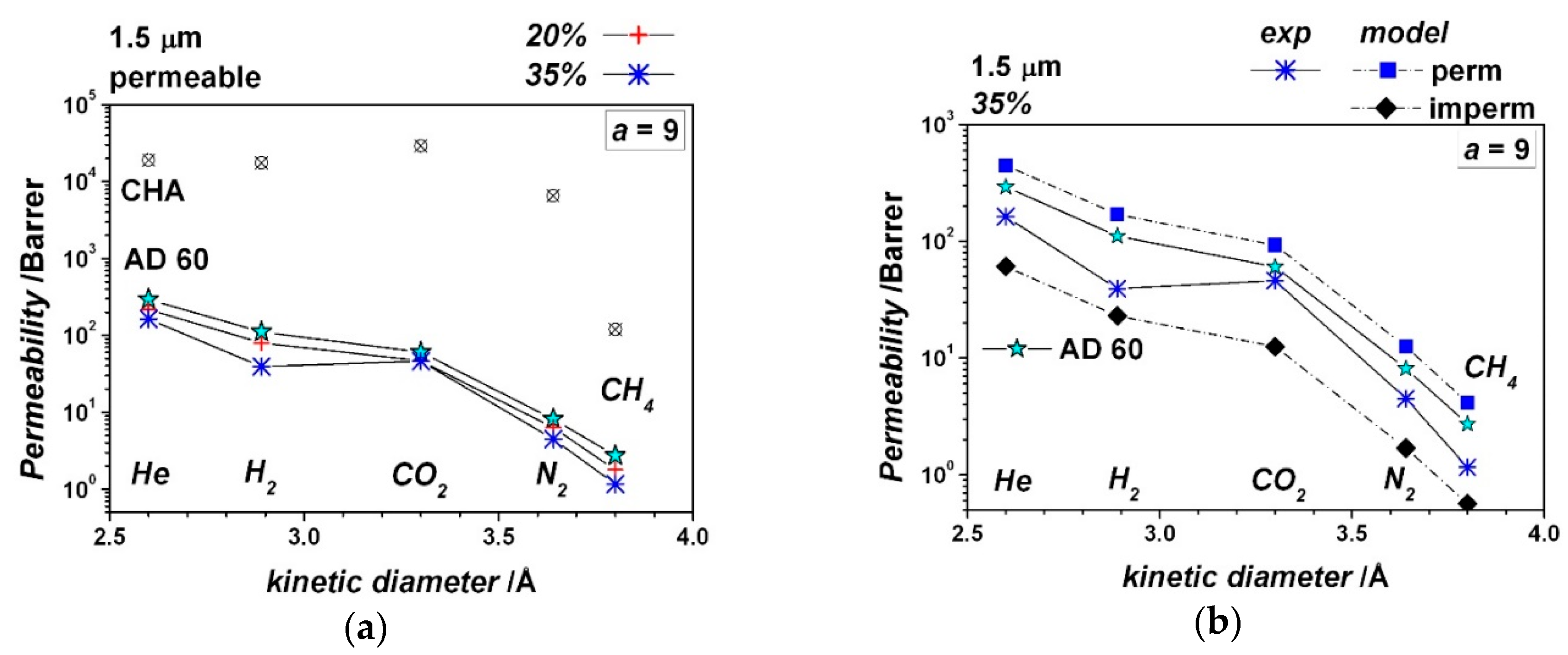
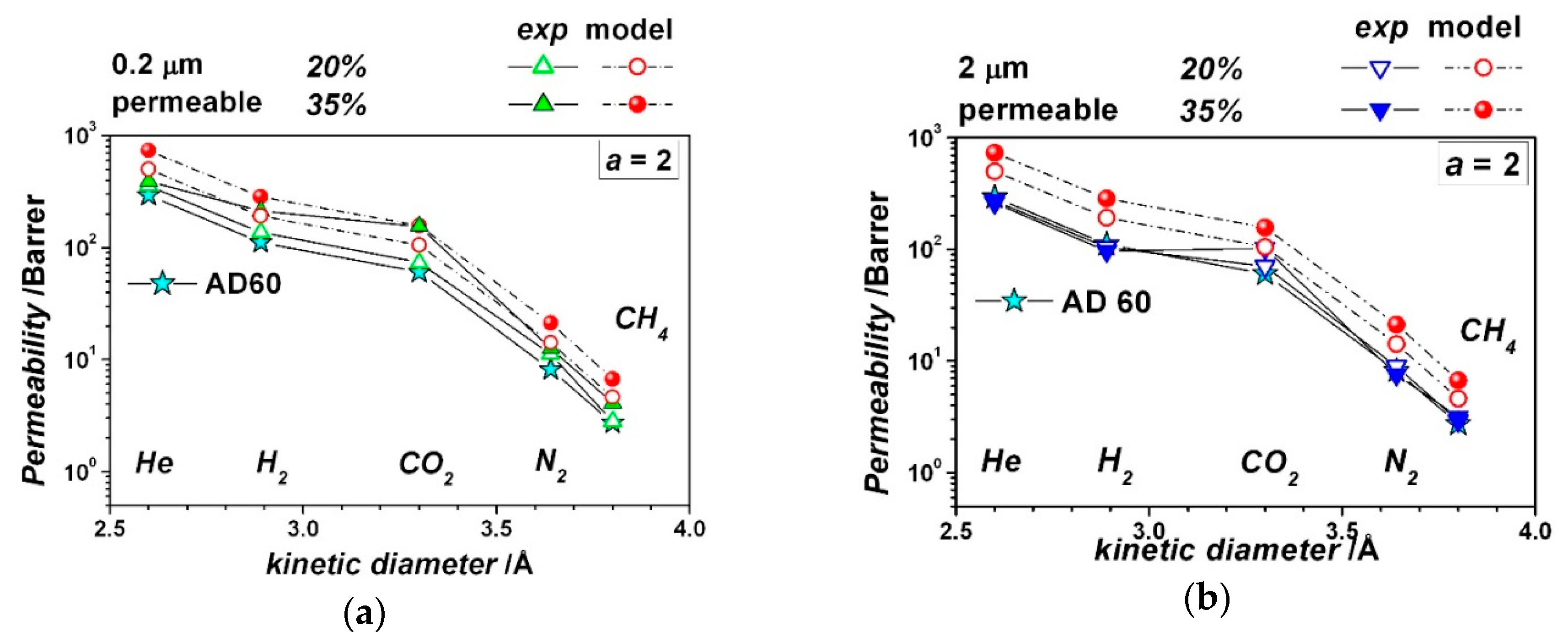
| Gas | He | H2 | CO2 | O2 | N2 | CH4 |
|---|---|---|---|---|---|---|
| dk/Å | 2.6 | 2.89 | 3.3 | 3.46 | 3.64 | 3.80 |
| Tc/K | 5.2 | 33.18 | 304.20 | 154.58 | 126.19 | 190.6 |
| Experiment No. | 5 | 6 | 7 | 8 | 9 | 10 |
|---|---|---|---|---|---|---|
| Crystal longest size, μm | 0.2 | 2 | 0.2 | 2 | 1.5 | 1.5 |
| Particle Aspect Ratio, - | 2 | 2 | 2 | 2 | 9 | 9 |
| Particle volume fraction, - | 0.20 | 0.20 | 0.35 | 0.35 | 0.20 | 0.35 |
© 2019 by the authors. Licensee MDPI, Basel, Switzerland. This article is an open access article distributed under the terms and conditions of the Creative Commons Attribution (CC BY) license (http://creativecommons.org/licenses/by/4.0/).
Share and Cite
Golemme, G.; Santaniello, A. Perfluoropolymer/Molecular Sieve Mixed-Matrix Membranes. Membranes 2019, 9, 19. https://doi.org/10.3390/membranes9020019
Golemme G, Santaniello A. Perfluoropolymer/Molecular Sieve Mixed-Matrix Membranes. Membranes. 2019; 9(2):19. https://doi.org/10.3390/membranes9020019
Chicago/Turabian StyleGolemme, Gianni, and Anna Santaniello. 2019. "Perfluoropolymer/Molecular Sieve Mixed-Matrix Membranes" Membranes 9, no. 2: 19. https://doi.org/10.3390/membranes9020019