Pilot–Scale Production of Carbon Hollow Fiber Membranes from Regenerated Cellulose Precursor-Part I: Optimal Conditions for Precursor Preparation


Abstract
:1. Introduction
2. Materials and Methods
2.1. Materials
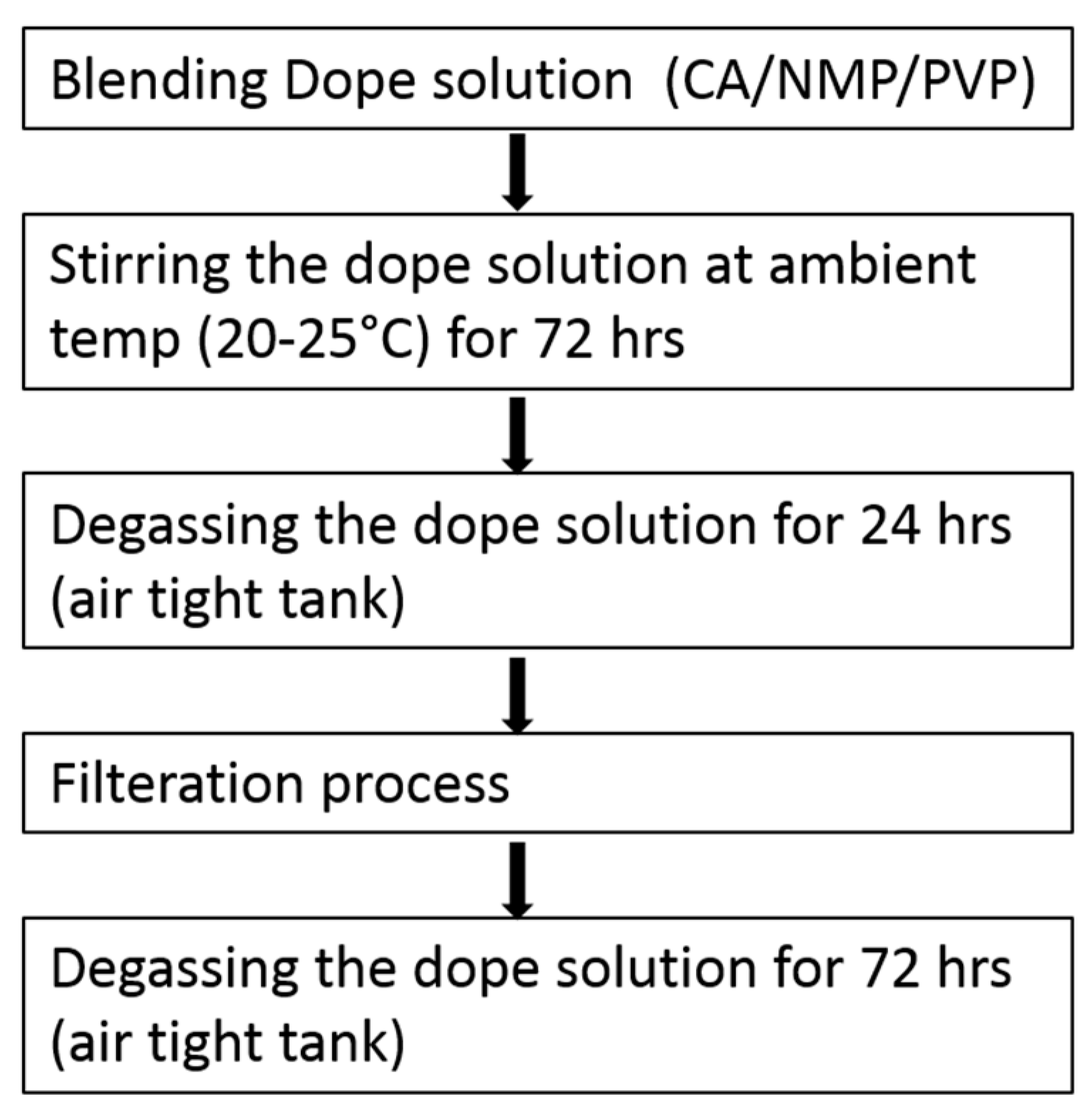
2.2. Dope and Bore Solution Preparation and Filtration
2.3. Spinning of CA Hollow Fibers
2.3.1. Fiber Collection Methods and Water Wash
Squared Collection Wheel
Circular Wheel with Perforated Collecting Plate
2.3.2. Glycerol Wash
2.3.3. Deacetylation
2.3.4. Glucose Wash
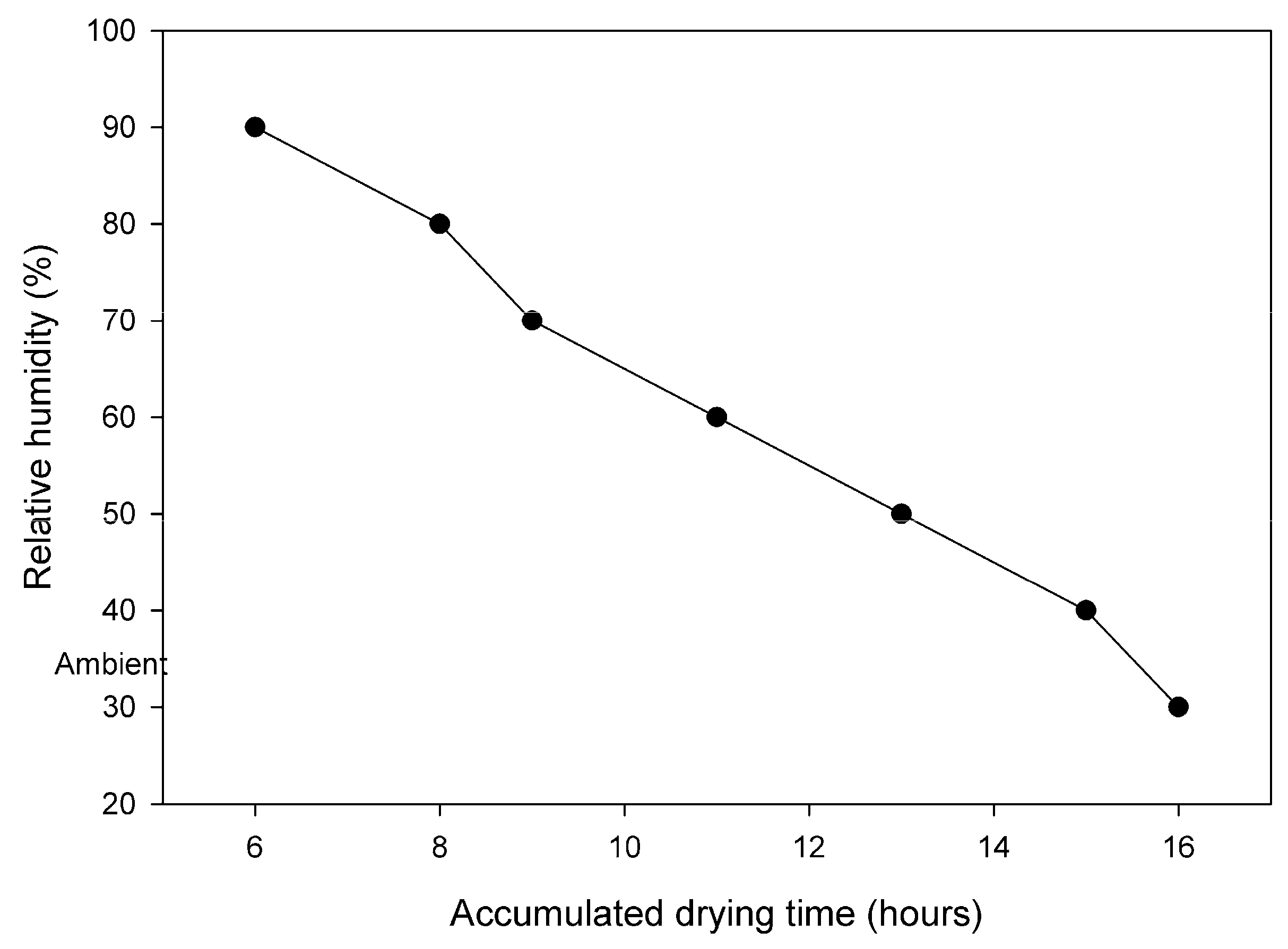
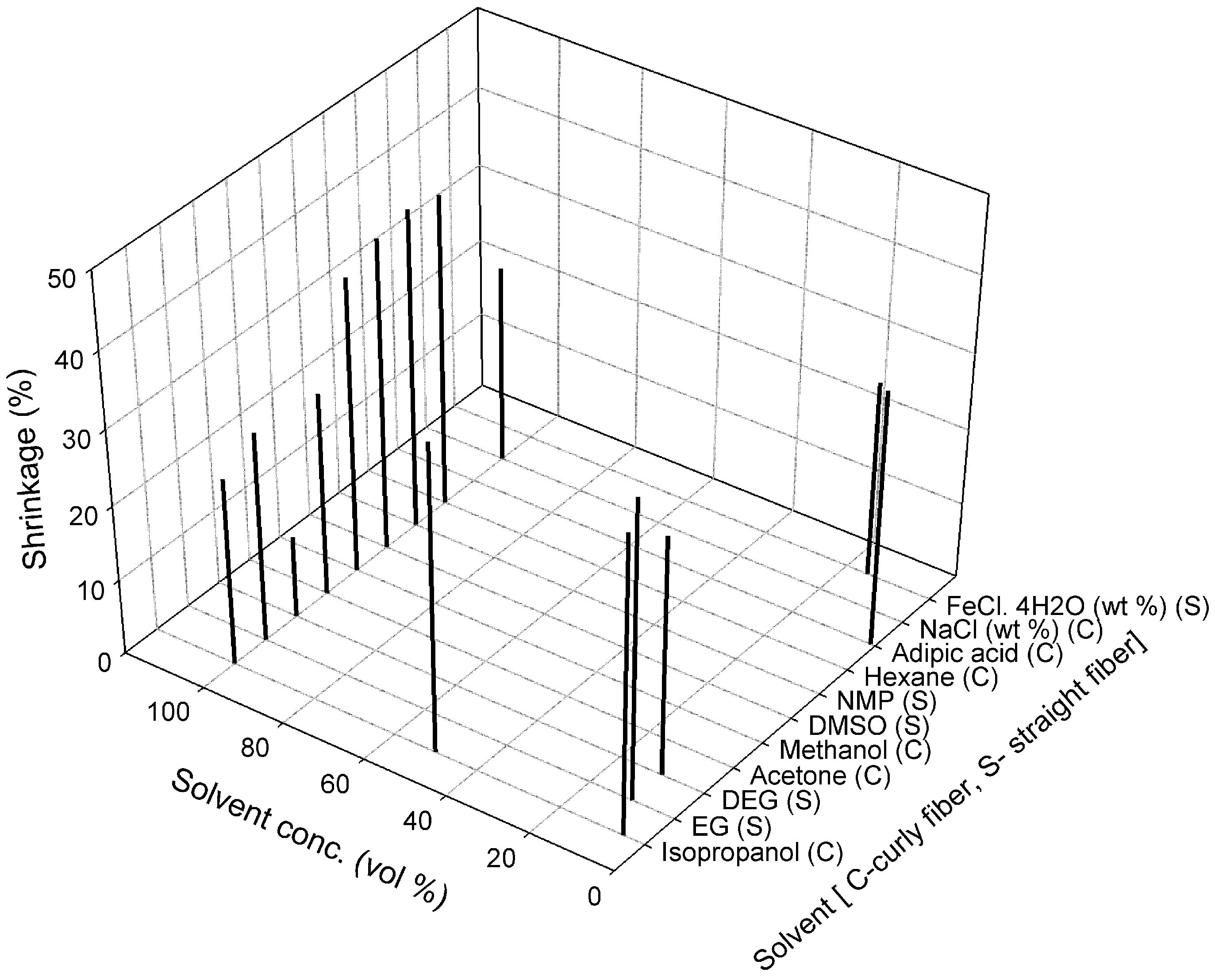
2.3.5. Drying
2.3.6. Measurements of Mechanical Properties of Fibers
2.4. Carbonization
2.5. Permeation Testing
3. Results and Discussion
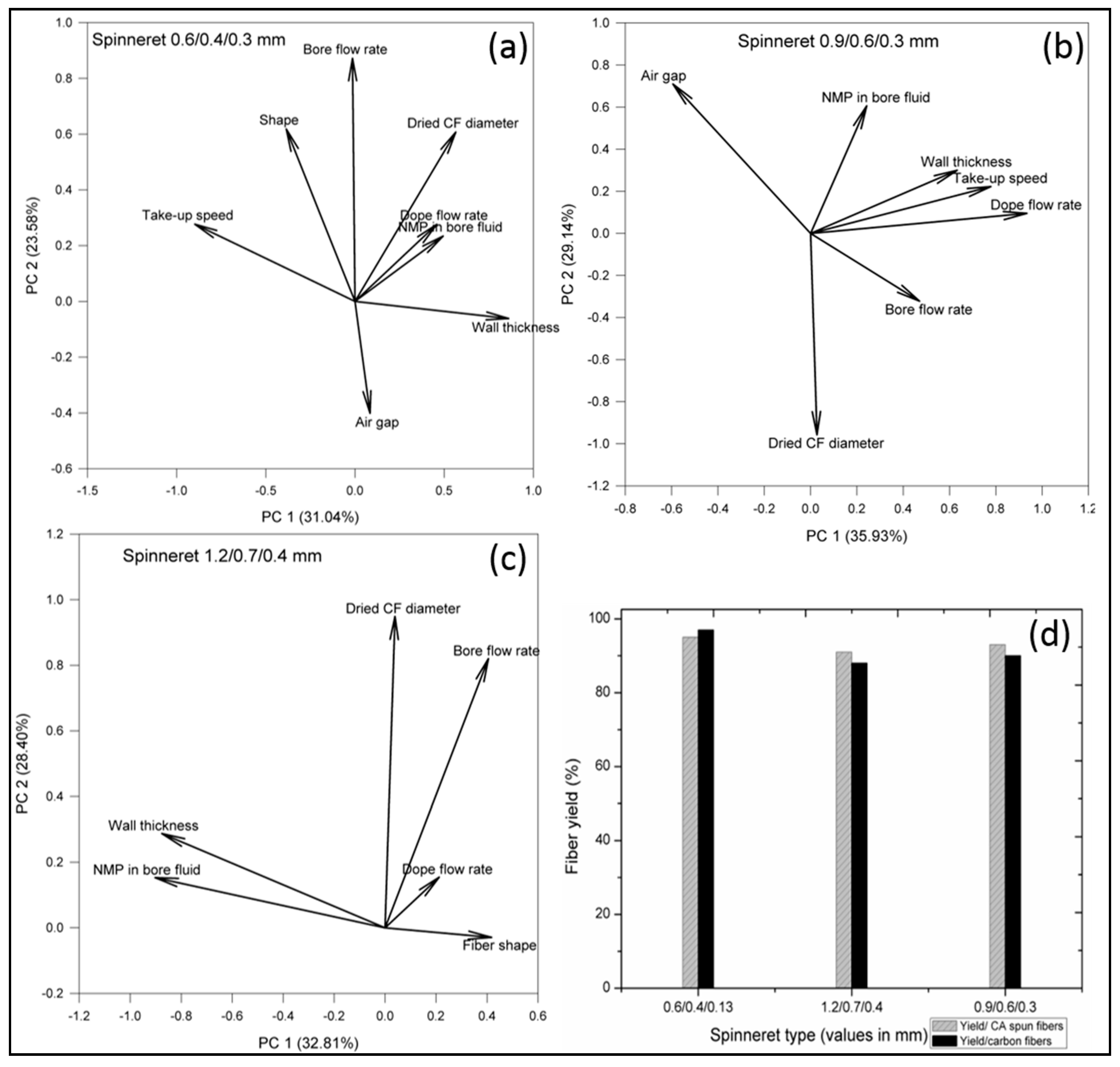
3.1. Effect of Spinning Parameters
3.2. Effect of Water and Glycerol Treatment
3.3. Effect of Deacetylation
3.4. Effect of Glucose Wash
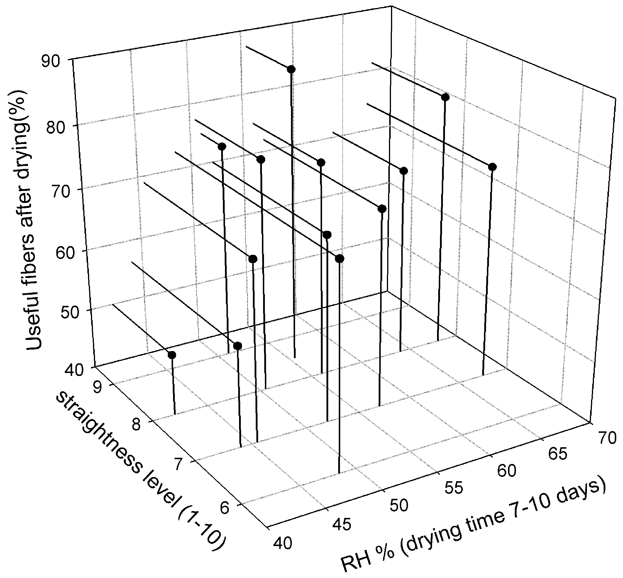
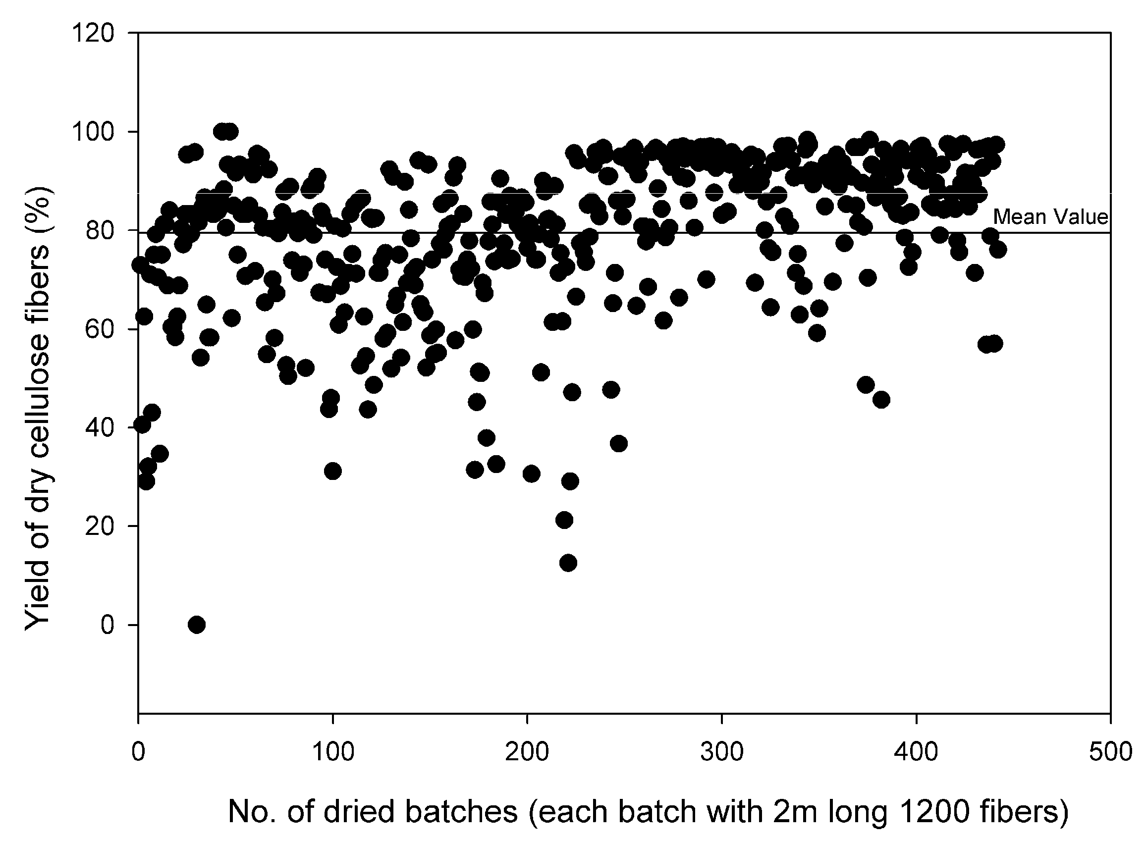
3.5. Dry Fibers
3.6. Carbonization and Gas Permeation Results
4. Conclusions
Author Contributions
Funding
Acknowledgments
Conflicts of Interest
Appendix A


References
- Ash, R.B.; Baker, R.W.; Barrer, R.M. Sorption and surface flow in graphitized carbon membranes—I. The steady state. Proc. R. Soc. Lond. Ser. A Math. Phys. Sci. 1967, 299, 434–454. [Google Scholar] [CrossRef]
- Aylmore, L.A.G.; Barrer, R.M. Surface and volume flow of single gases and of binary gas mixtures in a microporous carbon membrane. Proc. R. Soc. Lon. Ser. A Math. Phys. Sci. 1966, 290, 477–489. [Google Scholar] [CrossRef]
- Koresh, J.E.; Sofer, A. Molecular sieve carbon permselective membrane. Part I. Presentation of a new device for gas mixture separation. Sep. Sci. Technol. 1983, 18, 723–734. [Google Scholar] [CrossRef]
- Soffer, A.; Gilron, J.; Saguee, S.; Hed-Ofek, R.; Cohen, H. Process for the Production of Hollow Carbon Fiber Membranes. Patents EP0671202B1, 4 July 1995. [Google Scholar]
- Sun, N.; Swatloski, R.P.; Maxim, M.L.; Rahman, M.; Harland, A.G.; Haque, A.; Spear, S.K.; Daly, D.T.; Rogers, R.D. Magnetite-embedded cellulose fibers prepared from ionic liquid. J. Mater. Chem. 2008, 18, 283–290. [Google Scholar] [CrossRef]
- Lie, J.A.; Hägg, M.-B. Carbon membranes from cellulose: Synthesis, performance and regeneration. J. Membr. Sci. 2006, 284, 79–86. [Google Scholar] [CrossRef]
- Kawamoto, H.; Murayama, M.; Saka, S. Pyrolysis behavior of levoglucosan as an intermediate in cellulose pyrolysis: Polymerization into polysaccharide as a key reaction to carbonized product formation. J. Wood Sci. 2003, 49, 469–473. [Google Scholar] [CrossRef]
- Idris, A.; Ismail, A.F.; Shilton, S.J. Optimization of cellulose acetate hollow fiber reverse osmosis membrane production using Taguchi method. J. Membr. Sci. 2002, 205, 223–237. [Google Scholar] [CrossRef] [Green Version]
- Cao, S.; Shi, Y.; Chen, G. Influence of acetylation degree of cellulose acetate on pervaporation properties for MeOH/MTBE mixture. J. Membr. Sci. 2000, 165, 89–97. [Google Scholar] [CrossRef]
- Shieh, J.-J.; Chung, T.S. Effect of liquid-liquid demixing on the membrane morphology, gas permeation, thermal and mechanical properties of cellulose acetate hollow fibers. J. Membr. Sci. 1998, 140, 67–79. [Google Scholar] [CrossRef]
- Puleo, A.C.; Paul, D.R.; Kelley, S.S. The effect of degree of acetylation on gas sorption and transport behavior in cellulose acetate. J. Membr. Sci. 1989, 47, 301–332. [Google Scholar] [CrossRef]
- Yamashita, Y.; Endo, T. Deacetylation behavior of binary blend films of cellulose acetate and various polymers. J. Appl. Polym. Sci. 2006, 100, 1816–1823. [Google Scholar] [CrossRef]
- He, X.; Lie, J.A.; Sheridan, E.; Hägg, M.-B. Preparation and characterization of hollow fiber carbon membranes from cellulose acetate precursors. Ind. Eng. Chem. Res. 2011, 50, 2080–2087. [Google Scholar] [CrossRef]
- Haider, S.; Lindbråthen, A.; Lie, J.A.; Andersen, I.C.T.; Hägg, M.-B. CO2 separation with carbon membranes in high pressure and elevated temperature applications. Sep. Purif. Technol. 2018, 190, 177–189. [Google Scholar] [CrossRef]
- He, X.; Hägg, M.-B. Structural, kinetic and performance characterization of hollow fiber carbon membranes. J. Membr. Sci. 2012, 390–391, 23–31. [Google Scholar] [CrossRef]
- He, X.; Hägg, M.-B. Hollow fiber carbon membranes: Investigations for CO2 capture. J. Membr. Sci. 2011, 378, 1–9. [Google Scholar] [CrossRef]
- He, X.; Hägg, M.-B. Hollow fiber carbon membranes: From material to application. Chem. Eng. J. 2013, 215–216, 440–448. [Google Scholar] [CrossRef]
- Jie, X.; Cao, Y.; Lin, B.; Yuan, Q. Gas permeation performance of cellulose hollow fiber membranes made from the cellulose/N-methylmorpholine-N-oxide/H2O system. J. Appl. Polym. Sci. 2004, 91, 1873–1880. [Google Scholar] [CrossRef]
- Qin, J.-J.; Li, Y.; Lee, L.-S.; Lee, H. Cellulose acetate hollow fiber ultrafiltration membranes made from CA/PVP 360 K/NMP/water. J. Membr. Sci. 2003, 218, 173–183. [Google Scholar] [CrossRef]
- Liu, H.; Hsieh, Y.-L. Ultrafine fibrous cellulose membranes from electrospinning of cellulose acetate. J. Polym. Sci. Part B Polym. Phys. 2002, 40, 2119–2129. [Google Scholar] [CrossRef]
- Son, W.K.; Youk, J.H.; Lee, T.S.; Park, W.H. Electrospinning of ultrafine cellulose acetate fibers: Studies of a new solvent system and deacetylation of ultrafine cellulose acetate fibers. J. Polym. Sci. Part B Polym. Phy. 2004, 42, 5–11. [Google Scholar] [CrossRef]
- Olaru, N.; Olaru, L. Cellulose acetate deacetylation in benzene/acetic acid/water systems. J. Appl. Polym. Sci. 2004, 94, 1965–1968. [Google Scholar] [CrossRef]
- Yamashita, Y.; Endo, T. Deterioration behavior of cellulose acetate films in acidic or basic aqueous solutions. J. Appl. Polym. Sci. 2004, 91, 3354–3361. [Google Scholar] [CrossRef]
- Jie, X.; Cao, Y.; Qin, J.-J.; Liu, J.; Yuan, Q. Influence of drying method on morphology and properties of asymmetric cellulose hollow fiber membrane. J. Membr. Sci. 2005, 246, 157–165. [Google Scholar] [CrossRef] [Green Version]
- Lie, J.A.; Hägg, M.-B. Carbon Membranes. Patent US20100162887 A1, 1 July 2010. [Google Scholar]
- Sheridan, T.B.E.; Lie, J.A.; Hägg, M.-B. Carbon Membranes from Cellulose Esters. Patent US8394175 B2, 20 March 2013. [Google Scholar]
- He, X. Development of Hollow Fiber Carbon Membranes for CO2 Separation. Ph.D. Thesis, Norwegian University of Science and Technology, Trondheim, Norway, 2011. [Google Scholar]
- Lin, W.-H.; Vora, R.H.; Chung, T.-S. Gas transport properties of 6fda-durene/1,4-phenylenediamine (ppda) copolyimides. J. Polym. Sci. B Polym. Phys. 2000, 38, 2703–2713. [Google Scholar] [CrossRef]
- Lie, J.A. Synthesis, Performance and Regeneration of Carbon Membranes for Biogas Upgrading—A Future Energy Carrier. Ph.D. Thesis, Norwegian University of Science and Technology, Trondheim, Norway, 2005. [Google Scholar]
- Fu, X.Y.; Sotani, T.; Matsuyama, H. Effect of membrane preparation method on the outer surface roughness of cellulose acetate butyrate hollow fiber membrane. Desalination 2008, 233, 10–18. [Google Scholar] [CrossRef]
- Robeson, L.M. The upper bound revisited. J. Membr. Sci. 2008, 320, 390–400. [Google Scholar] [CrossRef]
- He, X. Optimization of deacetylation process for regenerated cellulose hollow fiber membranes. Int. J. Polym. Sci. 2017, 2017, 3125413. [Google Scholar] [CrossRef]
- Haider, S.; Lindbråthen, A.; Hägg, M.-B. Techno-economical evaluation of membrane based biogas upgrading system: A comparison between polymeric membrane and carbon membrane technology. Green Energy Environ. 2016, 1, 222–234. [Google Scholar] [CrossRef]


| Parameter | Values | Units |
|---|---|---|
| Dope Solution | ||
| Composition | 22.5 CA/5 PVP/72.5 NMP | wt% |
| flow rate | 0.4 | L/h |
| Temperature | RT (20–23) | °C |
| Bore Fluid | ||
| Composition | 30/35 H2O–65/70 NMP | vol% |
| flow rate | 0.2 | L/h |
| Temperature | RT (20–23) | °C |
| Other Parameters | ||
| Air gap | 25 | mm |
| Coagulation medium/T | H2O/RT (20–23) | °C |
| Godet bath temperature | 25–40 | °C |
| Collection wheel | 10 | °C |
| Take up speed | 14 | m/min |
| Post-Treatment | ||
| Water wash | 10 °C | 24 h |
| Glycerol wash | 7.5 vol% in water (20 °C) | 24 h |
| Deacetylation | 0.075 M NaOH (aqueous sol.) diluted with 10 vol% IP | 2.5 h |
| After wash | 7.5 wt% glucose (20 °C) | 30 min |
| Drying | T: 40–45 °C, RH: 90% → ambient | 16 h |
| Carbonization | ||
| Temperature | 550–650 °C, 2 h soak | |
| Medium | N2 or CO2 | 0.7–1.9 L/min |
© 2018 by the authors. Licensee MDPI, Basel, Switzerland. This article is an open access article distributed under the terms and conditions of the Creative Commons Attribution (CC BY) license (http://creativecommons.org/licenses/by/4.0/).
Share and Cite
Haider, S.; Lie, J.A.; Lindbråthen, A.; Hägg, M.-B. Pilot–Scale Production of Carbon Hollow Fiber Membranes from Regenerated Cellulose Precursor-Part I: Optimal Conditions for Precursor Preparation. Membranes 2018, 8, 105. https://doi.org/10.3390/membranes8040105
Haider S, Lie JA, Lindbråthen A, Hägg M-B. Pilot–Scale Production of Carbon Hollow Fiber Membranes from Regenerated Cellulose Precursor-Part I: Optimal Conditions for Precursor Preparation. Membranes. 2018; 8(4):105. https://doi.org/10.3390/membranes8040105
Chicago/Turabian StyleHaider, Shamim, Jon Arvid Lie, Arne Lindbråthen, and May-Britt Hägg. 2018. "Pilot–Scale Production of Carbon Hollow Fiber Membranes from Regenerated Cellulose Precursor-Part I: Optimal Conditions for Precursor Preparation" Membranes 8, no. 4: 105. https://doi.org/10.3390/membranes8040105