

Incipient Biofouling Detection via Fiber Optical Sensing and Image Analysis in Reverse Osmosis Processes
 , and
, and
Abstract
:1. Introduction
- A new fiber optical sensor for biofouling detection, which can be easily integrated into both newly constructed and existing SWMs. This sensor provides a reliable method for detecting biofouling in real time within the RO system.
- The implementation of image analysis techniques for membrane flat modules that are often used in laboratory experiments.
2. Materials and Methods
2.1. RO-Pilot Plant
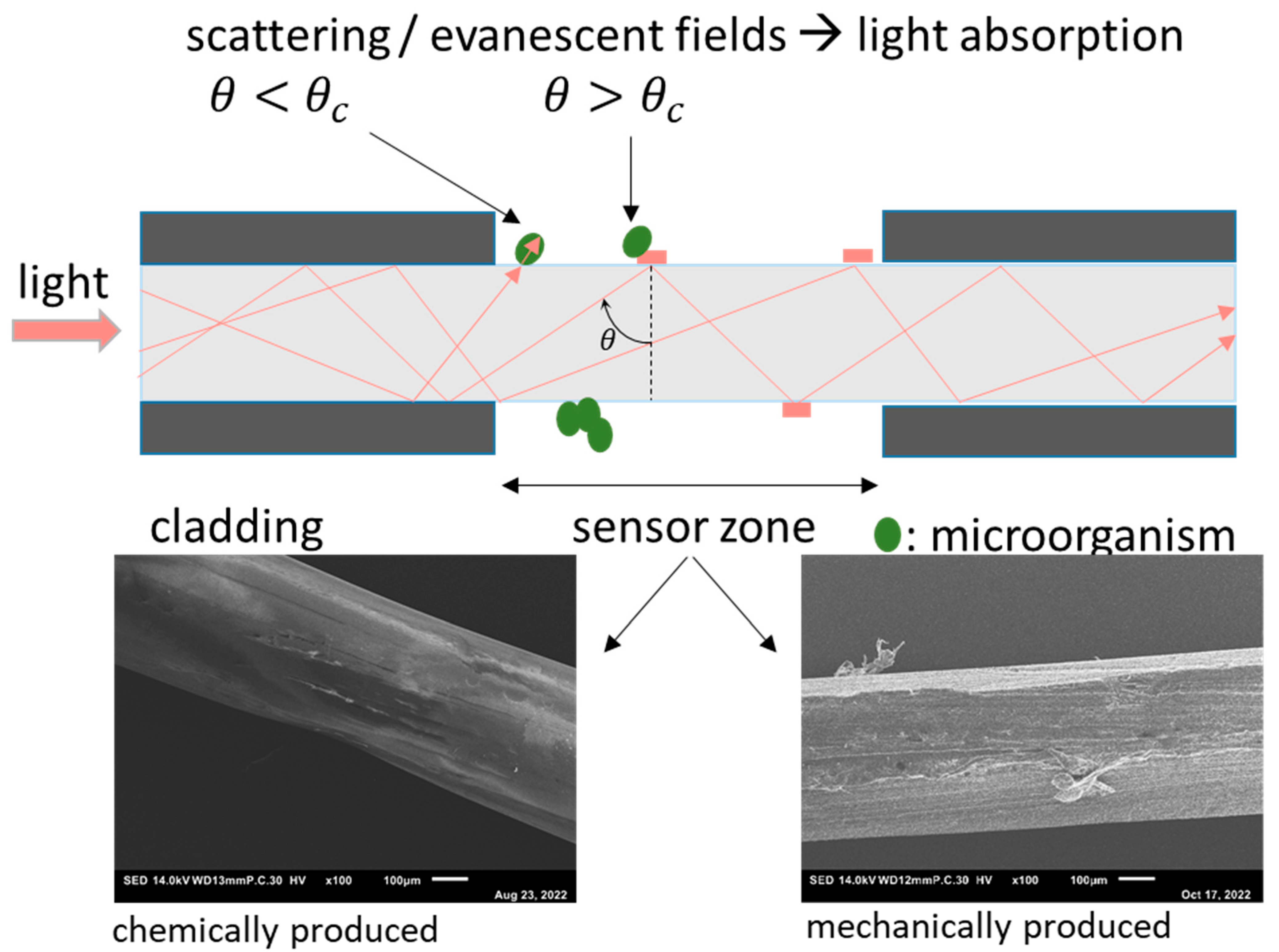
2.2. POF-Sensor
2.3. Offline Analytic
2.4. Online Analytic
2.5. Image Analysis
- (A)
- Image registration:The motion of the module (due to motor movement etc.) resulted in an imperfect alignment, so the captured images corresponded to different coordinates on the membrane surface. Therefore, it was necessary to perform image registration to align the images. This process followed the four steps of image registration as outlined by Zitová and Flusser [17]: feature detection, feature matching, transform model estimation, image resampling, and transformation.
- A distinctive section of the photo containing specific features of a cropped reference greyscale image was manually selected.
- The images were aligned. The Matlab® function normxcorr2 was used to create a normalized cross-correlation matrix between the selected feature image section and the sensed images of the time series, which were transformed into greyscale images. This function moves the smaller matrix containing the features across the bigger matrix to find the location via the maximum in matching [18]. Next, parameters for further transformation, namely aligning the sensed images around the selected features, had to be extracted using the Matlab® functions find and max.
- The gained parameters were then used to align the color images. To be able to transform the images around the same coordinates, they had to be cut in size; thus, gaining room for movement. Hence, the registered images were somewhat smaller than the original ones and consisted of 1937 × 2913 × 3 pixels. As a result of the registration process, all images of the time series had the same size and were centered around the same distinctive features.
- (B)
- Image similarities:
3. Results and Discussion
3.1. Conditioning: POF-Transmissions in Water
3.2. First Validation: POF-Sensors in a Yeast Suspension
3.3. Second Validation: Biofilm Detection in the RO Pilot Plant
3.4. Practical Test: POF-Sensors as Indicators of Cleaning-in-Place
4. Conclusions
- Image analysis can quantify the color changes caused by microbial growth at a very early stage. A preparatory step is needed to adjust the photo’s positions to the reference images recorded during the conditioning phase. A 2-dimensional Pearson correlation coefficient of the R-, G-, and B-layers was calculated for each photograph of the whole experimental series and compared with the reference image. This results in a time series of image analysis parameters that can be recorded while biofouling is affecting the RO process.
- Polymer optical fibers are a new method to detect biofouling throughout the entire growth period. The detection process requires the use of conditioned fibers and enables the qualitative detection of biological growth until the fiber surface is completely covered with biomass. The time series of the transmitted light through the fibers strongly differs from the changes observed in fibers used to monitor scaling (inorganic deposit) on the RO membrane.
Author Contributions
Funding
Acknowledgments
Conflicts of Interest
References
- Baten, R.; Stummeyer, K. How sustainable can desalination be? Desalination Water Treat. 2013, 51, 44–52. [Google Scholar] [CrossRef]
- Goh, P.S.; Lau, W.J.; Othman, M.; Ismail, A.F. Membrane fouling in desalination and its mitigation strategies. Desalination 2018, 425, 130–155. [Google Scholar] [CrossRef]
- Sperle, P.; Wurzbacher, C.; Drewes, J.E.; Skibinski, B. Reducing the Impacts of Biofouling in RO Membrane Systems through In Situ Low Fluence Irradiation Employing UVC-LEDs. Membranes 2020, 10, 415. [Google Scholar] [CrossRef]
- Flemming, H.-C.; Schaule, G.; Griebe, T.; Schmitt, J.; Tamachkiarowa, A. Biofouling—The Achilles heel of membrane processes. Desalination 1997, 113, 215–225. [Google Scholar] [CrossRef]
- Ismail, A.F.; Khulbe, K.C.; Matsuura, T. RO Membrane Fouling. In Reverse Osmosis; Elsevier: Amsterdam, The Netherlands, 2019; pp. 189–220. [Google Scholar]
- Flemming, H.-C. Reverse osmosis membrane biofouling. Experimental Therm. Fluid Sci. 1997, 14, 382–391. [Google Scholar] [CrossRef]
- Wu, W.; Wang, R.; Chang, H.; Zhong, N.; Zhang, T.; Wang, K.; Ren, N.; Ho, S.-H. Rational electron tunning of magnetic biochar via N, S co-doping for intense tetracycline degradation: Efficiency improvement and toxicity alleviation. Chem. Eng. J. 2023, 458, 141470. [Google Scholar] [CrossRef]
- Schmitt, J.; Nivensm, D.; White, D.-C.; Flemming, H.-C. Changes of biofilm properties in response to sorbed substances—An ftir-atr study. Water Sci. Technol. 1995, 32, 149–155. [Google Scholar] [CrossRef]
- Matin, A.; Khan, Z.; Zaidi, S.; Boyce, M.C. Biofouling in reverse osmosis membranes for seawater desalination: Phenomena and prevention. Desalination 2011, 281, 1–16. [Google Scholar] [CrossRef]
- Vrouwenvelder, J.S.; Bakker, S.M.; Wessels, L.P.; van Paassen, J. The Membrane Fouling Simulator as a new tool for biofouling control of spiral-wound membranes. Desalination 2007, 204, 170–174. [Google Scholar] [CrossRef]
- Vrouwenvelder, J.S.; Manolarakis, S.A.; van der Hoek, J.P.; van Paassen, J.A.M.; van der Meer, W.G.J.; van Agtmaal, J.M.C.; Prummel, H.D.M.; Kruithof, J.C.; van Loosdrecht, M.C.M. Quantitative biofouling diagnosis in full scale nanofiltration and reverse osmosis installations. Water Res. 2008, 42, 4856–4868. [Google Scholar] [CrossRef]
- Dreszer, C.; Flemming, H.-C.; Wexler, A.D.; Zwijnenburg, A.; Kruithof, J.C.; Vrouwenvelder, J.S. Development and testing of a transparent membrane biofouling monitor. Desalination Water Treat. 2014, 52, 1807–1819. [Google Scholar] [CrossRef]
- Hager, S.; Oesinghaus, H.; Bachmann, A.; Meinardus, M.; Hofmann, T.; Glas, K. CaCO3 deposits in reverse osmosis: Part III—Incipient Scaling detection via polymer optical fibre sensors. Comparison to hydrochemical prediction and image analytical methods. Brew. Sci. 2023, 76, 19–29. [Google Scholar] [CrossRef]
- Dreszer, C.; Vrouwenvelder, J.S.; Paulitsch-Fuchs, A.H.; Zwijnenburg, A.; Kruithof, J.C.; Flemming, H.-C. Hydraulic resistance of biofilms. J. Membr. Sci. 2013, 429, 436–447. [Google Scholar] [CrossRef]
- Hager, S.; Bachmann, A.; Hofmann, T.; Engelbrecht, R.; Glas, K. CaCO3 deposits in reverse osmosis Part I—Shortcomings of current approaches leading to a new prediction model and monitoring device. Brew. Sci. 2021, 74, 122–133. [Google Scholar]
- Reitmeier, S.; Kiessling, S.; Neuhaus, K.; Haller, D. Comparing Circadian Rhythmicity in the Human Gut Microbiome. STAR Protoc. 2020, 1, 100148. [Google Scholar] [CrossRef]
- Zitová, B.; Flusser, J. Image registration methods: A survey. Image Vis. Comput. 2003, 21, 977–1000. [Google Scholar] [CrossRef]
- Wright, D. Pseudo feature point registration of pavement images. J. Traffic Transp. Eng. 2018, 5, 254–267. [Google Scholar] [CrossRef]
- Mohapatra, S.; Weisshaar, J.C. Modified Pearson correlation coefficient for two-color imaging in spherocylindrical cells. BMC Bioinform. 2018, 19, 428. [Google Scholar] [CrossRef]
- Pearson, K. VII. Mathematical contributions to the theory of evolution—III. Regression, heredity, and panmixia. Phil. Trans. R. Soc. Lond. A 1986, 187, 253–318. [Google Scholar] [CrossRef]
- Peters, K. Polymer optical fiber sensors—A review. Smart Mater. Struct. 2011, 20, 13002. [Google Scholar] [CrossRef]
- Webb, D.J. Fibre Bragg grating sensors in polymer optical fibres. Meas. Sci. Technol. 2015, 26, 92004. [Google Scholar] [CrossRef]
- La, Y.-H.; Sooriyakumaran, R.; Miller, D.C.; Fujiwara, M.; Terui, Y.; Yamanaka, K.; McCloskey, B.D.; Freeman, B.D.; Allen, R.D. Novel thin film composite membrane containing ionizable hydrophobes: pH-dependent reverse osmosis behavior and improved chlorine resistance. J. Mater. Chem. 2010, 20, 4615. [Google Scholar] [CrossRef]
- Stolov, M.; Freger, V. Membrane Charge Weakly Affects Ion Transport in Reverse Osmosis. Environ. Sci. Technol. Lett. 2020, 7, 440–445. [Google Scholar] [CrossRef]
- Vrouwenvelder, J.S.; Graf von der Schulenburg, D.A.; Kruithof, J.C.; Johns, M.L.; van Loosdrecht, M.C.M. Biofouling of spiral-wound nanofiltration and reverse osmosis membranes: A feed spacer problem. Water Res. 2009, 43, 583–594. [Google Scholar] [CrossRef]
- Vrouwenvelder, J.S.; Kruithof, J.; van Loosdrecht, M. Biofouling of spiral wound membrane systems. Water Intell Online 2011, 10, 9781780400990. [Google Scholar] [CrossRef]
- De Vries, H.J.; Stams, A.J.M.; Plugge, C.M. Biodiversity and ecology of microorganisms in high pressure membrane filtration systems. Water Res. 2020, 172, 115511. [Google Scholar] [CrossRef]
- Sánchez, O. Microbial diversity in biofilms from reverse osmosis membranes: A short review. J. Membr. Sci. 2018, 545, 240–249. [Google Scholar] [CrossRef]
- Herzberg, M.; Elimelech, M. Physiology and genetic traits of reverse osmosis membrane biofilms: A case study with Pseudomonas aeruginosa. ISME J. 2008, 2, 180–194. [Google Scholar] [CrossRef]
- Buszewski, B.; Rogowska, A.; Pomastowski, P.; Złoch, M.; Railean-Plugaru, V. Identification of Microorganisms by Modern Analytical Techniques. J. AOAC Int. 2017, 100, 1607–1623. [Google Scholar] [CrossRef]
- Bereschenko, L.A.; Heilig, G.H.J.; Nederlof, M.M.; van Loosdrecht, M.C.M.; Stams, A.J.M.; Euverink, G.J.W. Molecular characterization of the bacterial communities in the different compartments of a full-scale reverse-osmosis water purification plant. Appl. Environ. Microbiol. 2008, 74, 5297–5304. [Google Scholar] [CrossRef]


| Phylum | Class | Order | Family | Genus |
|---|---|---|---|---|
| Proteobacteria | Gammaproteobacteria (typical biofilm formers) | Burkholderiales | Commamonadaceae | 48% Aquabacterium 29% Acidovorax 3% Delftla |
| Rhodocyclaceae Burkholderiaceae | 2% Ferribacterium 2% Cupriavidus | |||
| Xanthomonadaceae | 3% Pseudoxanthomonas 0.8% Stenotrophomonas | |||
| Pseudomonales | 4% Acinetobacter 1% Pseudomonas (human pathogenic) | |||
| Alphaproteobacteria (typical biofilm formers) | Caulobacteraceae | 6% Caulobacter 0.7% Phenylebacterium | ||
| Sphingomonadaceae | 0.8% Sphingopyxis | |||
| 1% Rhodobacter | ||||
| Bacteroidia | 0.8% Cytophaga (Coexisting within potable water biofilms [31]) |
Disclaimer/Publisher’s Note: The statements, opinions and data contained in all publications are solely those of the individual author(s) and contributor(s) and not of MDPI and/or the editor(s). MDPI and/or the editor(s) disclaim responsibility for any injury to people or property resulting from any ideas, methods, instructions or products referred to in the content. |
© 2023 by the authors. Licensee MDPI, Basel, Switzerland. This article is an open access article distributed under the terms and conditions of the Creative Commons Attribution (CC BY) license (https://creativecommons.org/licenses/by/4.0/).
Share and Cite
Oesinghaus, H.; Wanken, D.; Lupp, K.; Gastl, M.; Elsner, M.; Glas, K. Incipient Biofouling Detection via Fiber Optical Sensing and Image Analysis in Reverse Osmosis Processes. Membranes 2023, 13, 553. https://doi.org/10.3390/membranes13060553
Oesinghaus H, Wanken D, Lupp K, Gastl M, Elsner M, Glas K. Incipient Biofouling Detection via Fiber Optical Sensing and Image Analysis in Reverse Osmosis Processes. Membranes. 2023; 13(6):553. https://doi.org/10.3390/membranes13060553
Chicago/Turabian StyleOesinghaus, Helge, Daniel Wanken, Kilian Lupp, Martina Gastl, Martin Elsner, and Karl Glas. 2023. "Incipient Biofouling Detection via Fiber Optical Sensing and Image Analysis in Reverse Osmosis Processes" Membranes 13, no. 6: 553. https://doi.org/10.3390/membranes13060553