
Classical and Recent Developments of Membrane Processes for Desalination and Natural Water Treatment

Abstract
:1. Introduction
2. Previous Reviews
3. RO Desalination
3.1. Introduction
3.2. Membranes and Modules
3.3. Operation
- -
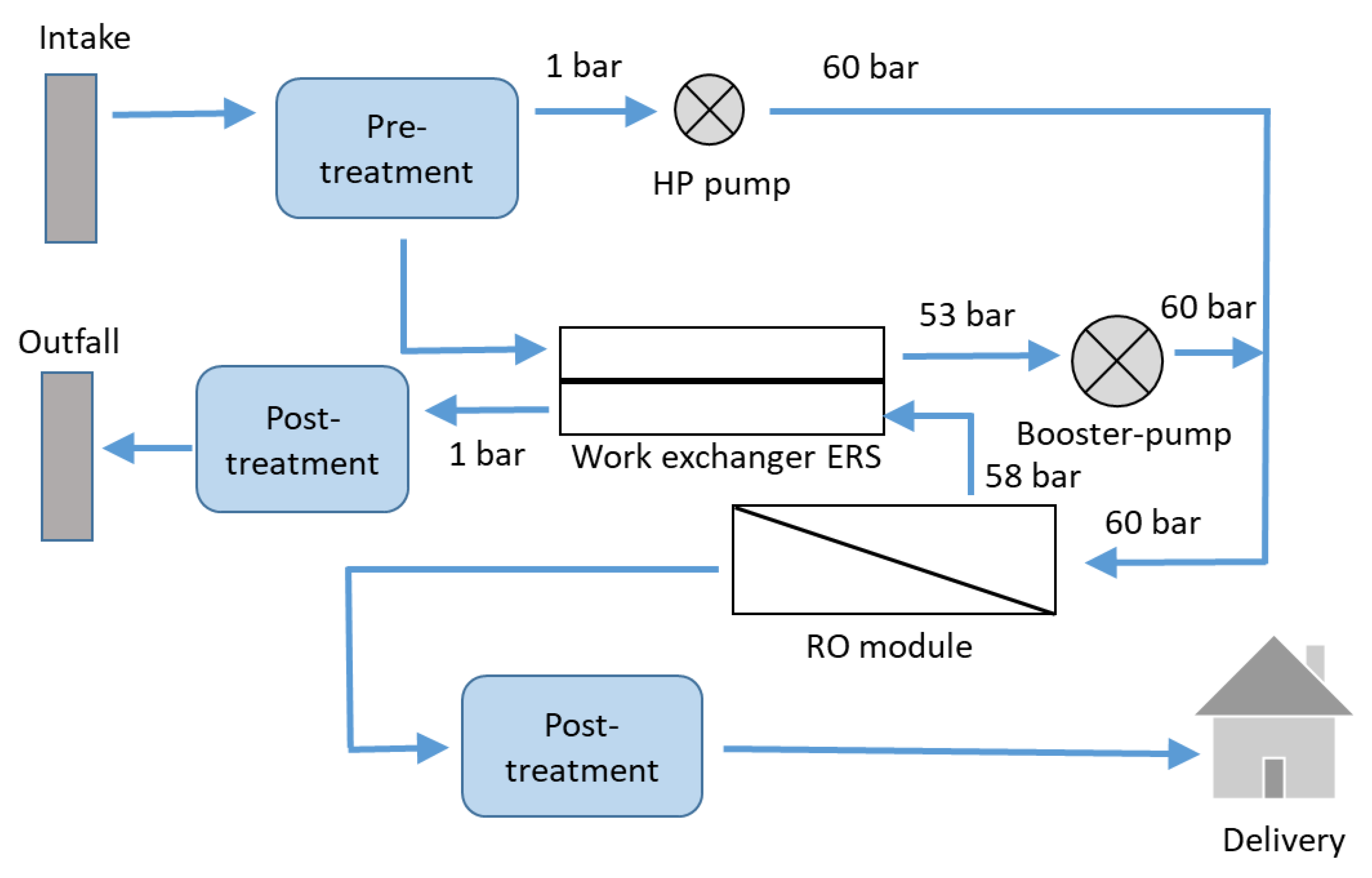
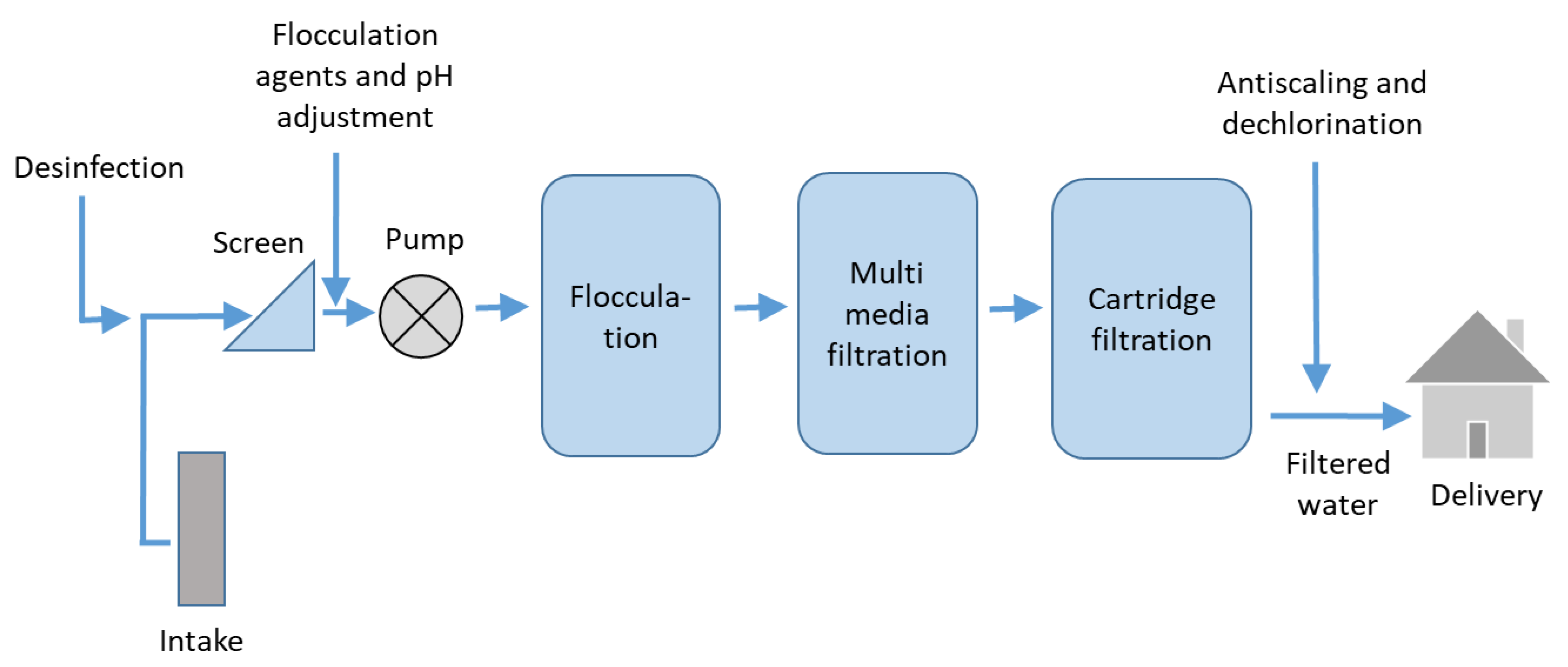
- The abstraction of feed water can be realised either through coastal and beach wells or through open seawater intake systems [1]. Abstraction through wells has several advantages: the water quality is better, with less turbidity, and less algae and total dissolved solids. However, wells require more space. In brackish water desalination, the abstraction of feed water is realized through wells.
- -
- In the pretreatment stage, colloids are removed from the feed water and chemicals are added to prevent scaling and fouling. The composition and pH of the intake water are adjusted. Pretreatment has a major influence on the RO performance by lowering the fouling propensity of the RO membranes. A specific section of this review is dedicated to pretreatment.
- -
- A pump is used to create the required transmembrane pressure and to overcome the height differences within pipes in the RO plant. High transmembrane pressure must be used (up to 7000 kPa) due to the high salt concentrations of seawater. The power required to pump the feed water is directly related to the feed pressure and flow rate [2].
- -
- The RO membranes separate salt from water with a rejection of 98–99.5%, depending on the membranes used. Several RO plants operate with either one, two or four RO passes [2]. The choice between one or more RO passes depends on several factors, including energy cost, feed water, desired recovery, and product water standards.
- -
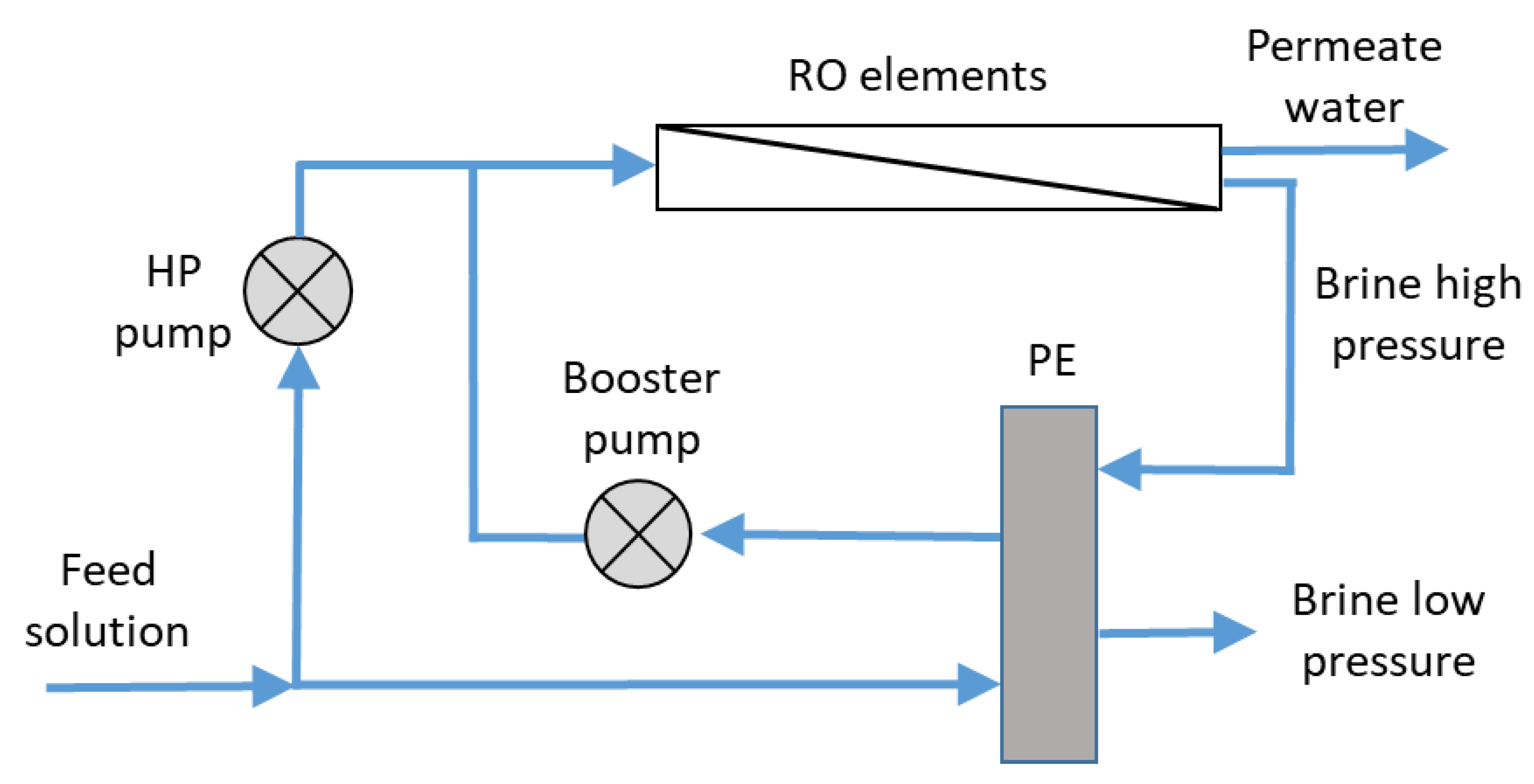
- The energy recovery system is aimed at transferring the potential energy from the concentrate to the feed. Current energy recovery systems operate with efficiencies greater than 95%. Several energy recovery devices are available. The most common uses hydraulic power to cause a positive displacement within the recovery device [2]. Several RO plants use these devices, such as the DWEER (DWEER Technology, Ltd., George Town, Cayman Islands), PX Exchanger (ERI), or PES (Siemag’s Pressure Exchanger System) [2].
3.4. Boron Removal
3.5. Fouling
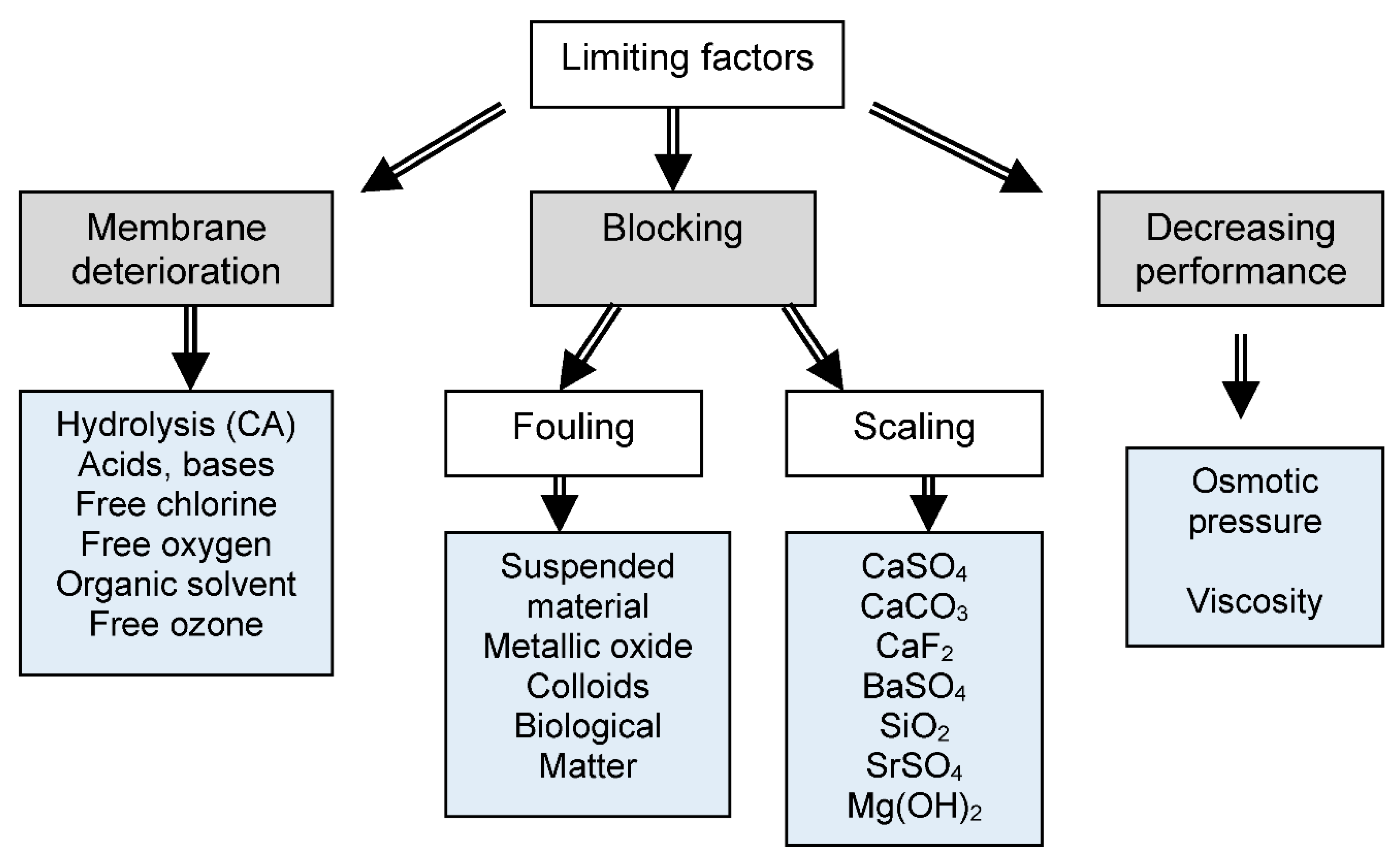
3.5.1. Scaling
3.5.2. Biofouling
3.5.3. Algal Blooms
3.5.4. Cleaning
3.6. Pretreatment Prior to RO
3.6.1. Conventional Treatments
3.6.2. Membrane Processes
3.7. Energy
3.8. Environmental Issues
3.9. Other Membrane Processes for Desalination
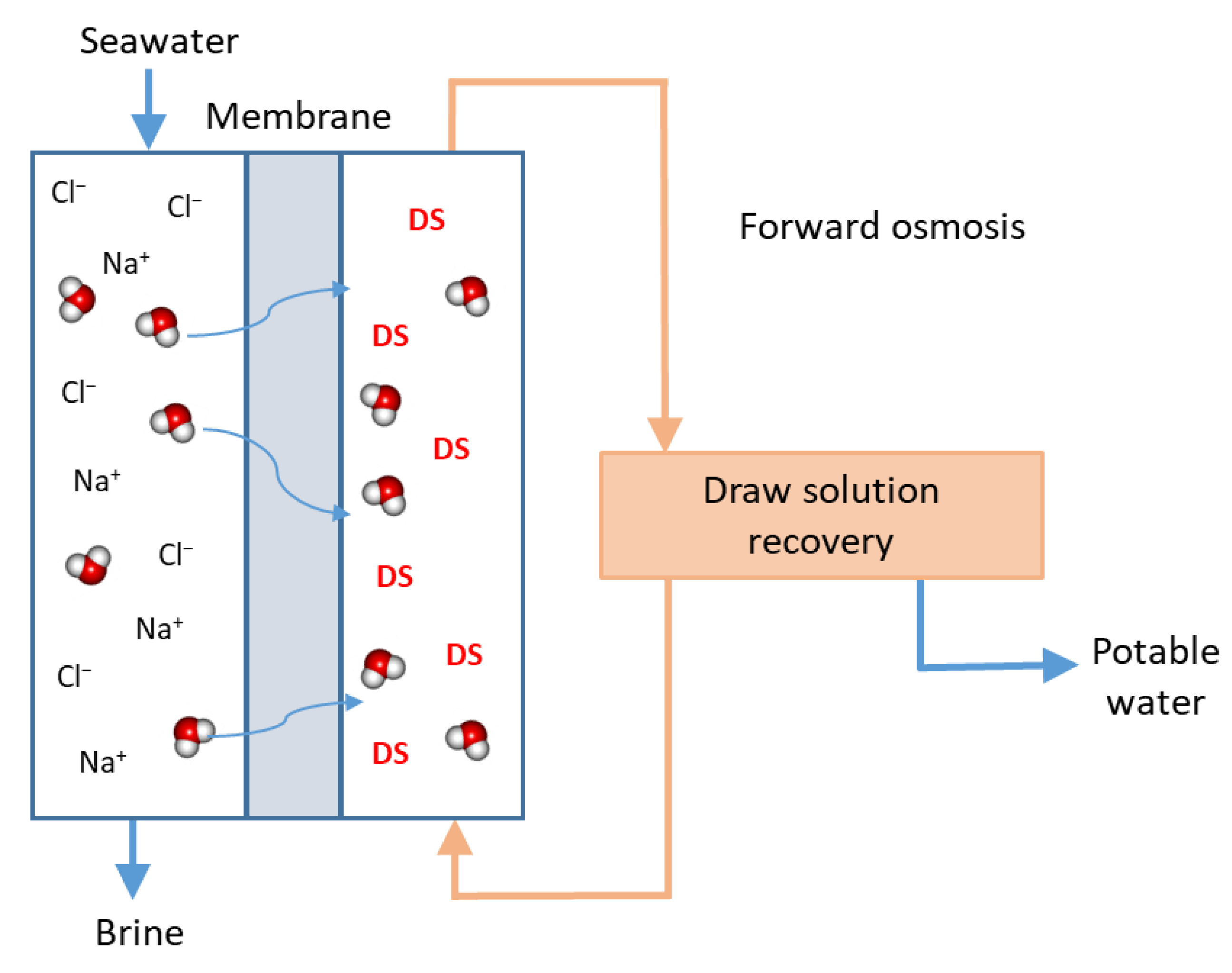
3.9.1. Forward Osmosis
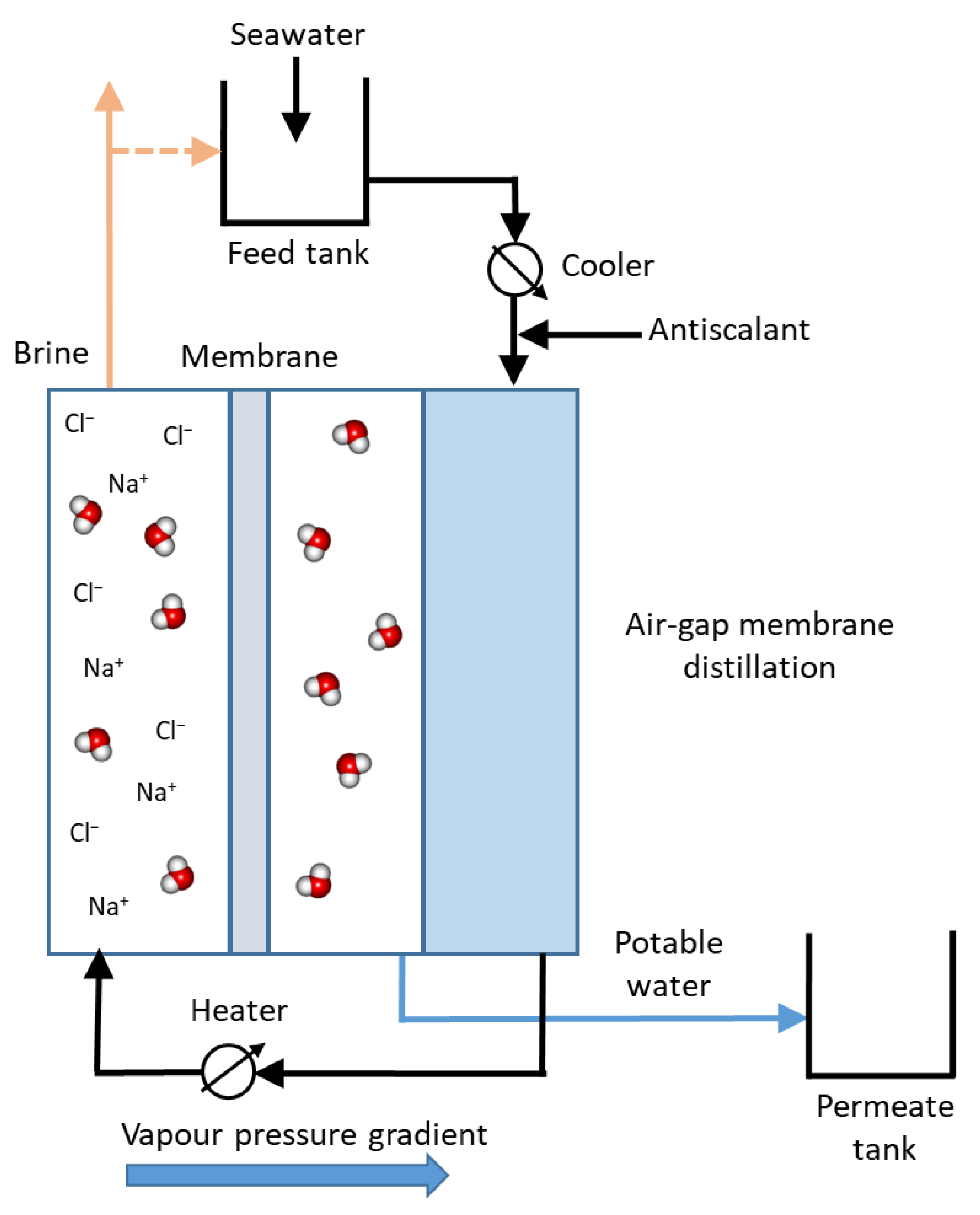
3.9.2. Membrane Distillation
3.9.3. Electrodialysis
4. Removal of Specific Compounds in Natural Water
4.1. Introduction
4.2. Natural Organic Matter
4.3. Arsenic
4.4. Iron
4.5. Nitrate
4.6. Fluor
4.7. Removal of Pesticides and Herbicides
4.8. Pharmaceuticals and Personal Care Products
5. Conclusions
Funding
Data Availability Statement
Conflicts of Interest
References
- Fritzmann, C.; Löwenberg, J.; Wintgens, T.; Melin, T. State-of-the-art of reverse osmosis desalination. Desalination 2007, 216, 1–76. [Google Scholar] [CrossRef]
- Greenlee, L.F.; Lawler, D.F.; Freeman, B.D.; Marrot, B.; Moulin, P. Reverse osmosis desalination: Water sources, technology, and today’s challenges. Water Res. 2009, 43, 2317–2348. [Google Scholar] [CrossRef] [PubMed]
- Lee, K.P.; Arnot, T.C.; Mattia, D. A review of reverse osmosis membrane materials for desalination—Development to date and future potential. J. Membr. Sci. 2011, 370, 1–22. [Google Scholar] [CrossRef] [Green Version]
- Patel, S.K.; Ritt, C.L.; Deshmukh, A.; Wang, Z.; Qin, M.; Epsztein, R.; Elimelech, M. The relative insignificance of advanced materials in enhancing the energy efficiency of desalination technologies. Energy Environ. Sci. 2020, 13, 1694–1710. [Google Scholar] [CrossRef] [Green Version]
- Shenvi, S.S.; Isloor, A.M.; Ismail, A.F. A review on RO membrane technology: Developments and challenges. Desalination 2015, 368, 10–26. [Google Scholar] [CrossRef]
- Qasim, M.; Badrelzaman, M.; Darwish, N.N.; Darwish, N.A.; Hilal, N. Reverse osmosis desalination: A state-of-the-art review. Desalination 2019, 459, 59–104. [Google Scholar] [CrossRef] [Green Version]
- Miller, S.; Shemer, H.; Semiat, R. Energy and environmental issues in desalination. Desalination 2015, 366, 2–8. [Google Scholar] [CrossRef]
- Elimelech, M.; Phillip, W.A. The future of seawater desalination: Energy, technology, and the environment. Science 2011, 333, 712–717. [Google Scholar] [CrossRef]
- Kim, J.; Park, K.; Yang, D.R.; Hong, S. A comprehensive review of energy consumption of seawater reverse osmosis desalination plants. Appl. Energy 2019, 254, 113652. [Google Scholar] [CrossRef]
- Park, K.; Kim, J.; Yang, D.R.; Hong, S. Towards a low-energy seawater reverse osmosis desalination plant: A review and theoretical analysis for future directions. J. Membr. Sci. 2020, 595, 117607. [Google Scholar] [CrossRef]
- Nassrullah, H.; Anisa, S.F.; Hashaikeha, R.; Hilal, N. Energy for desalination: A state-of-the-art review. Desalination 2022, 522, 115441. [Google Scholar] [CrossRef]
- Matin, A.; Khan, Z.; Zaidi, S.M.J.; Boyce, M.C. Biofouling in reverse osmosis membranes for seawater desalination: Phenomena and prevention. Desalination 2011, 281, 1–16. [Google Scholar] [CrossRef]
- Matin, A.; Rahman, F.; Shafi, H.Z.; Zubair, S.M. Scaling of reverse osmosis membranes used in water desalination: Phenomena, impact, and control; future directions. Desalination 2019, 455, 135–157. [Google Scholar] [CrossRef]
- Villacorte, L.O.; Tabatabai, S.A.A.; Anderson, D.M.; Amy, G.L.; Schippers, J.C.; Kennedy, M.D. Seawater reverse osmosis desalination and (harmful) algal blooms. Desalination 2015, 360, 61–80. [Google Scholar] [CrossRef]
- Ghaffour, N.; Bundschuh, J.; Mahmoudi, H.; Goosen, M.F.A. Renewable energy-driven desalination technologies: A comprehensive review on challenges and potential applications of integrated systems. Desalination 2015, 356, 94–114. [Google Scholar] [CrossRef] [Green Version]
- Kalogirou, S.A. Seawater desalination using renewable energy sources. Prog. Energy Combust. Sci. 2005, 31, 242–281. [Google Scholar] [CrossRef]
- Charcosset, C. A review of membrane processes and renewable energies for desalination. Desalination 2009, 245, 214–231. [Google Scholar] [CrossRef]
- Bundschuh, J.; Kaczmarczyk, M.; Ghaffour, N.; Tomaszewska, B. State-of-the-art of renewable energy sources used in water desalination: Present and future prospects. Desalination 2021, 508, 115035. [Google Scholar] [CrossRef]
- Wu, W.; Shi, Y.; Liu, G.; Fan, X.; Yu, Y. Recent development of graphene oxide based forward osmosis membrane for water treatment: A critical review. Desalination 2020, 491, 114452. [Google Scholar] [CrossRef]
- Lee, W.; Ng, Z.; Hubadillah, S.; Goh, P.; Lau, W.; Othman, M.; Ismail, A.; Hilal, N. Fouling mitigation in forward osmosis and membrane distillation for desalination. Desalination 2020, 480, 114338. [Google Scholar] [CrossRef]
- Awad, A.M.; Jalab, R.; Minier-Matar, J.; Adham, S.; Nasser, M.S.; Judd, S.J. The status of forward osmosis technology implementation. Desalination 2019, 461, 10–21. [Google Scholar] [CrossRef]
- Skuse, C.; Gallego-Schmid, A.; Azapagic, A.; Gorgojo, P. Can emerging membrane-based desalination technologies replace reverse osmosis? Desalination 2021, 500, 114844. [Google Scholar] [CrossRef]
- Ahmed, F.E.; Khalil, A.; Hilal, N. Emerging desalination technologies: Current status, challenges and future trends. Desalination 2021, 517, 115183. [Google Scholar] [CrossRef]
- Hilal, N.; Kim, G.; Somerfield, C. Boron removal from saline water: A comprehensive review. Desalination 2011, 273, 23–35. [Google Scholar] [CrossRef]
- Chaturvedi, S.; Dave, P.N. Removal of iron for safe drinking water. Desalination 2012, 303, 1–11. [Google Scholar] [CrossRef]
- Shrimali, M.; Singh, K.P. New methods of nitrate removal from water. Environ. Pollut. 2001, 112, 351–359. [Google Scholar] [CrossRef]
- Mohapatra, M.; Anand, S.; Mishra, B.; Giles, D.E.; Singh, P. Review of fluoride removal from drinking water. J. Environ. Manag. 2009, 91, 67–77. [Google Scholar] [CrossRef]
- Damtie, M.M.; Woo, Y.C.; Kim, B.; Hailemariam, R.H.; Park, K.D.; Shon, H.K.; Park, C.; Choi, J.S. Removal of fluoride in membrane-based water and wastewater treatment technologies: Performance review. J. Environ. Manag. 2019, 251, 109524. [Google Scholar] [CrossRef]
- Plakas, K.V.; Karabelas, A.J. Removal of pesticides from water by NF and RO membranes—A review. Desalination 2012, 287, 255–265. [Google Scholar] [CrossRef]
- Yang, Y.; Ok, Y.S.; Kim, K.-H.; Kwon, E.E.; Tsang, Y.F. Occurrences and removal of pharmaceuticals and personal care products (PPCPs) in drinking water and water/sewage treatment plants: A review. Sci. Total Environ. 2017, 596–597, 303–320. [Google Scholar] [CrossRef]
- Khanzada, N.K.; Farid, M.U.; Kharraz, J.A.; Choi, J.; Tang, C.Y.; Nghiem, L.D.; Jang, A.; An, A.K. Removal of organic micropollutants using advanced membrane-based water and wastewater treatment: A review. J. Membr. Sci. 2020, 598, 117672. [Google Scholar] [CrossRef]
- Loeb, S.; Sourirajan, S. High Flow Porous Membranes for Separation of Water from Saline Solutions. U.S. Patent 3,133,132, 12 May 1964. [Google Scholar]
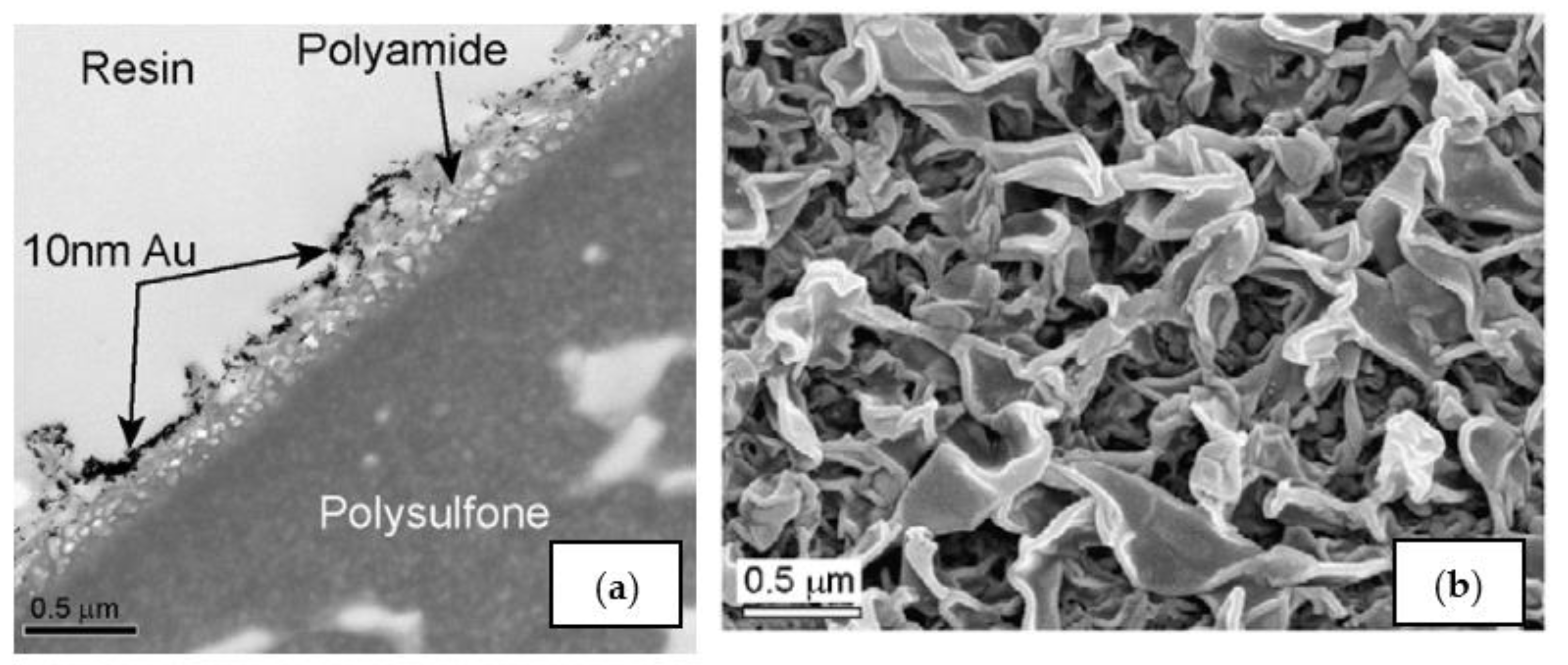
- Pacheco, F.A.; Pinnau, I.; Reinhard, M.; Leckie, J.O. Characterization of isolated polyamide thin films of RO and NF membranes using novel TEM techniques. J. Membr. Sci. 2010, 358, 51–59. [Google Scholar] [CrossRef]
- Zhao, S.; Liao, Z.; Fane, A.; Li, J.; Tang, C.; Zheng, C.; Lin, J.; Kong, L. Engineering antifouling reverse osmosis membranes: A review. Desalination 2021, 499, 114857. [Google Scholar] [CrossRef]
- Hao, Z.; Zhao, S.; Li, Q.; Wang, Y.; Zhang, J.; Wang, Z.; Wang, J. Reverse osmosis membranes with sulfonate and phosphate groups having excellent anti- scaling and anti-fouling properties. Desalination 2021, 509, 115076. [Google Scholar] [CrossRef]
- Tian, M.; Xu, H.; Yao, L.; Wang, R. A biomimetic antimicrobial surface for membrane fouling control in reverse osmosis for seawater desalination. Desalination 2021, 503, 114954. [Google Scholar] [CrossRef]
- Yao, Y.; Zhang, X. Chlorine resistant reverse osmosis membrane: A call for reform of desalination treatment processes. Desalination 2020, 501, 114907. [Google Scholar] [CrossRef]
- Al-Najar, B.; Peters, C.D.; Albuflasa, H.; Hankins, N.P. Pressure and osmotically driven membrane processes: A review of the benefits and production of nano-enhanced membranes for desalination. Desalination 2020, 479, 114323. [Google Scholar] [CrossRef]
- Farhat, A.; Ahmad, F.; Hilal, N.; Arafat, H.A. Boron removal in new generation reverse osmosis (RO) membranes using two-pass RO without pH adjustment. Desalination 2013, 310, 50–59. [Google Scholar] [CrossRef]
- Jung, B.; Kim, C.Y.; Jiao, S.; Rao, U.; Dudchenko, A.V.; Tester, J.; Jassby, D. Enhancing boron rejection on electrically conducting reverse osmosis membranes through local electrochemical pH modification. Desalination 2020, 476, 114212. [Google Scholar] [CrossRef]
- Kabay, N.; Köseoğlu, P.; Yavuz, E.; Yüksel, Ü.; Yüksel, M. An innovative integrated system for boron removal from geothermal water using RO process and ion exchange-ultrafiltration hybrid method. Desalination 2013, 316, 1–7. [Google Scholar] [CrossRef]
- Alharati, A.; Swesi, Y.; Fiaty, K.; Charcosset, C. Boron removal in water using a hybrid membrane process of ion exchange resin and microfiltration without continuous resin addition. J. Water Process Eng. 2017, 17, 32–39. [Google Scholar] [CrossRef]
- Herzberg, M.; Elimelech, M. Biofouling of reverse osmosis membranes: Role of biofilm-enhanced osmotic pressure. J. Membr. Sci. 2007, 295, 11–20. [Google Scholar] [CrossRef]
- Semiat, R.; Sutzkover, I.; Hasson, D. Characterization of the effectiveness of silica anti-scalants. Desalination 2003, 159, 11–19. [Google Scholar] [CrossRef]
- Thompson, J.; Rahardianto, A.; Kim, S.; Bilal, M.; Breckenridge, R.; Cohen, Y. Real-time direct detection of silica scaling on RO membranes. J. Membr. Sci. 2017, 528, 346–358. [Google Scholar] [CrossRef] [Green Version]
- Pomerantz, N.; Ladizhansky, Y.; Korin, E.; Waisman, M.; Daltrophe, N.; Gilron, J. Prevention of scaling of reverse osmosis membranes by “zeroing” the elapsed nucleation time. Part, I. Calcium sulfate. Ind. Eng. Chem. Res. 2006, 45, 2008–2016. [Google Scholar] [CrossRef]
- Goh, P.S.; Zulhairuna, A.K.; Ismail, A.F.; Hilal, N. Contemporary antibiofouling modifications of reverse osmosis desalination membrane: A review. Desalination 2019, 468, 114072–114096. [Google Scholar] [CrossRef]
- Richlen, M.L.; Morton, S.L.; Jamali, E.A.; Rajan, A.; Anderson, D.M. The catastrophic 2008–2009 red tide in the Arabian Gulf region, with observations on the identification and phylogeny of the fish-killing dinoflagellate Cochlodinium polykrikoides. Harmful Algae 2010, 9, 163–172. [Google Scholar] [CrossRef]
- Jiang, S.X.; Li, Y.N.; Ladewig, B.P. A review of reverse osmosis membrane fouling and control strategies. Sci. Total Environ. 2017, 595, 567–583. [Google Scholar] [CrossRef] [PubMed]
- Lee, Y.-G.; Kim, S.; Shin, J.; Rho, H.; Kim, Y.M.; Cho, K.H.; Eom, H.; Oh, S.-E.; Cho, J.; Chon, K. Sequential effects of cleaning protocols on desorption of reverse osmosis membrane foulants: Autopsy results from a full-scale desalination plant. Desalination 2020, 500, 114830. [Google Scholar] [CrossRef]
- Qin, J.J.; Oo, M.H.; Kekre, K.A.; Liberman, B. Development of novel backwash cleaning technique for reverse osmosis in reclamation of secondary effluent. J. Membr. Sci. 2010, 346, 8–14. [Google Scholar] [CrossRef]
- Pearce, G.K.; Talo, S.; Chida, K.; Basha, A.; Gulamhusein, A. Pre-treatment options for large scale SWRO plants: Case study of UF trials at Kindasa, Saudi Arabia, and conventional pre-treatment in Spain. Desalination 2004, 167, 175–189. [Google Scholar] [CrossRef]
- Al-Amoudi, A.S.; Farooque, A.M. Performance restoration and autopsy of NF membranes used in seawater pretreatment. Desalination 2005, 178, 261–271. [Google Scholar] [CrossRef]
- Song, D.; Zhang, Y.; Wang, H.; Jiang, L.; Wang, C.; Wang, S.; Jiang, Z.; Li, H. Demonstration of a piston type integrated high pressure pump-energy recovery device for reverse osmosis desalination system. Desalination 2021, 507, 115033. [Google Scholar] [CrossRef]
- Karabelas, A.; Koutsou, C.; Kostoglou, M.; Sioutopoulos, D. Analysis of specific energy consumption in reverse osmosis desalination processes. Desalination 2018, 431, 15–21. [Google Scholar] [CrossRef]
- Avlonitis, S.A.; Kouroumbas, K.; Vlachakis, N. Energy consumption and membrane replacement cost for seawater RO desalination plants. Desalination 2003, 157, 151–158. [Google Scholar] [CrossRef]
- Li, S.; Cai, Y.-H.; Schäfer, A.I.; Richards, B.S. Renewable energy powered membrane technology: A review of the reliability of photovoltaic-powered membrane system components for brackish water desalination. Appl. Energy 2019, 253, 113524. [Google Scholar] [CrossRef]
- Delgado-Torres, A.M.; García-Rodríguez, L. Status of solar thermal-driven reverse osmosis desalination. Desalination 2007, 216, 242–251. [Google Scholar] [CrossRef]
- Carta, J.A.; Gonzalez, J.; Subiela, V. Operational analysis of an innovative wind powered reverse osmosis system installed in the Canary Islands. Sol. Energy 2003, 75, 153–168. [Google Scholar] [CrossRef]
- Rosales-Asensio, E.; Borge-Diez, D.; Pérez-Hoyos, A.; Colmenar-Santos, A. Reduction of water cost for an existing wind-energy-based desalination scheme: A preliminary configuration. Energy 2019, 167, 548–560. [Google Scholar] [CrossRef]
- Stuyfzand, P.J.; Kappelhof, J.W.N.M. Floating, high-capacity desalting islands on renewable multienergy. Desalination 2005, 177, 259–266. [Google Scholar] [CrossRef]
- Brodersen, K.M.; Bywater, E.A.; Lanter, A.M.; Schennum, H.H.; Furia, K.N.; Sheth, M.K.; Kiefer, N.S.; Cafferty, B.K.; Rao, A.K.; Garcia, J.M.; et al. Direct-drive ocean wave-powered batch reverse osmosis. Desalination 2022, 523, 115393. [Google Scholar] [CrossRef]
- Missimer, T.M.; Ghaffour, N.; Dehwah, A.H.; Rachman, R.; Maliva, R.G.; Amy, G. Subsurface intakes for seawater reverse osmosis facilities: Capacity limitation, water quality improvement, and economics. Desalination 2013, 322, 37–51. [Google Scholar] [CrossRef]
- Ahmed, M.; Arakel, A.; Hoey, D.; Thumarukudy, M.R.; Goosen, M.F.; Al-Haddabi, M.; Al-Belushi, A. Feasibility of salt production from inland RO desalination plant reject brine: A case study. Desalination 2003, 158, 109–117. [Google Scholar] [CrossRef]
- Alameddine, I.; El-Fadel, M. Brine discharge from desalination plants: A modeling approach to an optimized outfall design. Desalination 2007, 214, 241–260. [Google Scholar] [CrossRef]
- Brover, S.; Lester, Y.; Brenner, A.; Sahar-Hadar, E. Optimization of ultrafiltration as pre-treatment for seawater RO desalination. Desalination 2021, 524, 115478. [Google Scholar] [CrossRef]
- Gryta, M. Osmotic MD and other membrane distillation variants. J. Membr. Sci. 2005, 246, 145–156. [Google Scholar] [CrossRef]
- Al-Obaidani, S.; Curcio, E.; Macedonio, F.; Profio, G.D.; Al-Hinai, H.; Drioli, E. Potential of membrane distillation in seawater desalination: Thermal efficiency, sensitivity study and cost estimation. J. Membr. Sci. 2008, 323, 85–98. [Google Scholar] [CrossRef]
- Banat, F.; Jwaied, N.; Rommel, M.; Koschikowski, J.; Wieghaus, M. Performance evaluation of the “large SMADES” autonomous desalination solar driven membrane distillation plant in Aqaba, Jordan. Desalination 2007, 217, 17–28. [Google Scholar] [CrossRef]
- Hanemaaijer, J.H.; van Medevoort, J.; Jansen, A.E.; Dotremont, C.; van Sonsbeek, E.; Yuan, T.; de Ryck, L. Memstill membrane distillation—A future desalination technology. Desalination 2006, 199, 175–176. [Google Scholar] [CrossRef]
- Tufa, R.A.; Noviello, Y.; Di Profio, G.; Macedonio, F.; Ali, A.; Drioli, E.; Fontananova, E.; Bouzek, K.; Curcio, E. Integrated membrane distillation-reverse electrodialysis system for energy-efficient seawater desalination. Appl. Energy 2019, 253, 113551. [Google Scholar] [CrossRef]
- AlMadani, H. Water desalination by solar powered electrodialysis process. Renew. Energy 2003, 28, 1915–1924. [Google Scholar] [CrossRef]
- Al-Amshawee, S.; Yunus, M.Y.B.M.; Azoddein, A.A.M.; Hassell, D.G.; Dakhil, I.H. and Hasan, H.A. Electrodialysis desalination for water and wastewater: A review. Chem. Eng. J. 2020, 380, 122231. [Google Scholar] [CrossRef]
- Veza, J.; Peñate, B.; Castellano, F. Electrodialysis desalination designed for off-grid wind energy. Desalination 2004, 160, 211–221. [Google Scholar] [CrossRef]
- Logan, B.E.; Elimelech, M. Membrane-based processes for sustainable power generation using water. Nature 2012, 488, 313–319. [Google Scholar] [CrossRef]
- Chen, Q.; Liu, Y.Y.; Xue, C.; Yang, Y.L.; Zhang, W.M. Energy self-sufficient desalination stack as a potential fresh water supply on small islands. Desalination 2015, 359, 52–58. [Google Scholar] [CrossRef]
- Doornbusch, G.; van der Wal, M.; Tedesco, M.; Post, J.; Nijmeijer, K.; Borneman, Z. Multistage electrodialysis for desalination of natural seawater. Desalination 2021, 505, 114973. [Google Scholar] [CrossRef]
- Matilainen, A.; Vepsäläinen, M.; Sillanpää, M. Natural organic matter removal by coagulation during drinking water treatment: A review. Adv. Colloid Interface Sci. 2010, 159, 189–197. [Google Scholar] [CrossRef]
- Seidel, A.; Elimelech, M. Coupling between chemical and physical interactions in natural organic matter (NOM) fouling of nanofiltration membranes: Implications for fouling control. J. Membr. Sci. 2002, 203, 245–255. [Google Scholar] [CrossRef]
- Cornelissen, E.R.; Harmsen, D.J.H.; Blankert, B.; Wessels, L.P.; van der Meer, W.G.J. Effect of minimal pre-treatment on reverse osmosis using surface water as a source. Desalination 2021, 509, 115056. [Google Scholar] [CrossRef]
- Pontié, M.; Charcosset, C. Chapter 7: Seawater, Brackish Waters, and Natural Waters Treatment with Hybrid Membrane Processes. In Integrated Membrane Systems and Processes; Basile, C.A., Ed.; Wiley: Hoboken, NJ, USA, 2016. [Google Scholar]
- Park, H.; Kim, Y.; An, B.; Choi, H. Characterization of natural organic matter treated by iron oxide nanoparticle incorporated ceramic membrane-ozonation process. Water Res. 2012, 46, 5861–5870. [Google Scholar] [CrossRef] [PubMed]
- Derlon, N.; Desmond, P.; Rühs, P.A.; Morgenroth, E. Cross flow frequency determines the physical structure and cohesion of membrane biofilms developed during gravity-driven membrane ultrafiltration of river water: Implication for hydraulic resistance. J. Membr. Sci. 2021, 643, 120079. [Google Scholar] [CrossRef]
- Pal, P.; Chakrabortty, S.; Linnanen, L. A nanofiltration-coagulation integrated system for separation and stabilization of arsenic from groundwater. Sci. Total Environ. 2014, 476–477, 601–610. [Google Scholar] [CrossRef]
- Park, H.; Choi, H. As(III) removal by hybrid reactive membrane process combined with ozonation. Water Res. 2011, 45, 1933–1940. [Google Scholar] [CrossRef]
- Boussouga, Y.A.; Frey, H.; Schäfer, A.I. Removal of arsenic(V) by nanofiltration: Impact of water salinity, pH and organic matter. Desalination 2021, 618, 118631. [Google Scholar] [CrossRef]
- Wickramasinghe, S.R.; Han, B.; Zimbron, J.; Shen, Z.; Karim, M.N. Arsenic removal by coagulation and filtration: Comparison of groundwaters from the United States and Bangladesh. Desalination 2004, 169, 231–244. [Google Scholar] [CrossRef]
- Santoro, S.; Timpano, P.; Avci, A.H.; Argurio, P.; Chidichimo, F.; De Biase, M.; Straface, S.; Curcio, E. An integrated membrane distillation, photocatalysis and polyelectrolyte-enhanced ultrafiltration process for arsenic remediation at point-of-use. Desalination 2021, 520, 115378. [Google Scholar] [CrossRef]
- Regis, A.O.; Vanneste, J.; Acker, S.; Martínez, G.; Ticona, J.; García, V.; Alejo, F.D.; Zea, J.; Krahenbuhl, R.; Vanzin, G.; et al. Pressure-driven membrane processes for boron and arsenic removal: pH and synergistic effects. Desalination 2022, 522, 115441. [Google Scholar] [CrossRef]
- El Azher, N.; Gourich, B.; Vial, C.; Soulami, M.B.; Ziyad, M. Study of ferrous iron oxidation in Morocco drinking water in an airlift reactor. Chem. Eng. Process. Process Intensif. 2008, 47, 1877–1886. [Google Scholar] [CrossRef]
- Fakhfekh, R.; Chabanon, E.; Mangin, D.; Amar, R.B.; Charcosse, C. Removal of iron using an oxidation and ceramic microfiltration hybrid process for drinking water treatment. Desalination Water Treat. 2017, 6, 1–11. [Google Scholar] [CrossRef]
- Chen, W.H.; Hsieh, Y.H.; Wu, C.C.; Wan, M.W.; Futalan, C.M.; Kan, C.C. The on-site feasibility study of iron and manganese removal from groundwater by hollow-fiber microfiltration. J. Water Supply Res. Technol. Aqua. 2011, 60, 391–401. [Google Scholar] [CrossRef]
- Epsztein, R.; Nir, O.; Lahav, O.; Green, M. Selective nitrate removal from groundwater using a hybrid nanofiltration-reverse osmosis filtration scheme. Chem. Eng. J. 2015, 279, 372–378. [Google Scholar] [CrossRef]
- Van der Bruggen, B.; Everaert, K.; Wilms, D.; Vandecasteele, C. Application of nanofiltration for the removal of pesticides, nitrate and hardness from ground water: Retention properties and economic evaluation. J. Membr. Sci. 2001, 193, 239–248. [Google Scholar] [CrossRef]
- Schoeman, J.; Steyn, A. Nitrate removal with reverse osmosis in a rural area in South Africa. Desalination 2003, 155, 15–26. [Google Scholar] [CrossRef]
- Pontié, M.; Dach, H.; Leparc, J.; Hafsi, M.; Lhassani, A. Novel approach combining physico-chemical characterizations and mass transfer modelling of nanofiltration and low pressure reverse osmosis membranes for brackish water desalination intensification. Desalination 2008, 221, 174–191. [Google Scholar] [CrossRef]
- Pontié, M.; Dach, H.; Lhassani, A.; Diawara, C.K. Water defluoridation using nanofiltration vs. reverse osmosis: The first world unit, Thiadiaye (Senegal). Desalination Water Treat. 2012, 51, 164–168. [Google Scholar] [CrossRef]
- Zhang, Y.; van der Bruggen, B.; Chen, G.X.; Braeken, L.; Vandecasteele, C. Removal of pesticides by nanofiltration: Effect of the water matrix. Sep. Purif. Technol. 2004, 38, 163–172. [Google Scholar] [CrossRef]
- Snyder, S.A.; Adham, S.; Redding, A.M.; Cannon, F.S.; Carolisb, J.D.; Oppenheimer, J.; Wert, C.; Yoon, Y. Role of membranes and activated carbon in the removal of endocrine disruptors and pharmaceuticals. Desalination 2007, 202, 156–181. [Google Scholar] [CrossRef]
- Taheran, M.; Brar, S.K.; Verma, M.; Surampalli, R.Y.; Zhang, T.C.; Valero, J.R. Membrane processes for removal of pharmaceutically active compounds (PhACs) from water and wastewaters. Sci. Total Environ. 2016, 547, 60–77. [Google Scholar] [CrossRef]


Publisher’s Note: MDPI stays neutral with regard to jurisdictional claims in published maps and institutional affiliations. |
© 2022 by the author. Licensee MDPI, Basel, Switzerland. This article is an open access article distributed under the terms and conditions of the Creative Commons Attribution (CC BY) license (https://creativecommons.org/licenses/by/4.0/).
Share and Cite
Charcosset, C. Classical and Recent Developments of Membrane Processes for Desalination and Natural Water Treatment. Membranes 2022, 12, 267. https://doi.org/10.3390/membranes12030267
Charcosset C. Classical and Recent Developments of Membrane Processes for Desalination and Natural Water Treatment. Membranes. 2022; 12(3):267. https://doi.org/10.3390/membranes12030267
Chicago/Turabian StyleCharcosset, Catherine. 2022. "Classical and Recent Developments of Membrane Processes for Desalination and Natural Water Treatment" Membranes 12, no. 3: 267. https://doi.org/10.3390/membranes12030267