
An Activated Bismuth Layer Formed In Situ on a Solid Bismuth Microelectrode for Electrochemical Sensitive Determination of Ga(III)

Abstract
:1. Introduction
2. Experimental
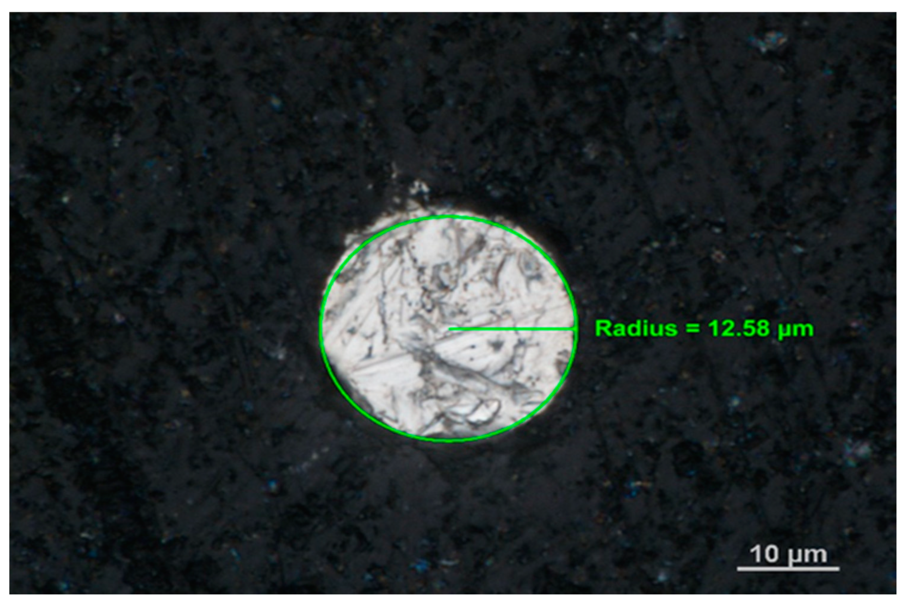
2.1. Apparatus
2.2. Reagents
2.3. Real Sample Preparation
2.4. Measurement Procedure
3. Results and Discussion
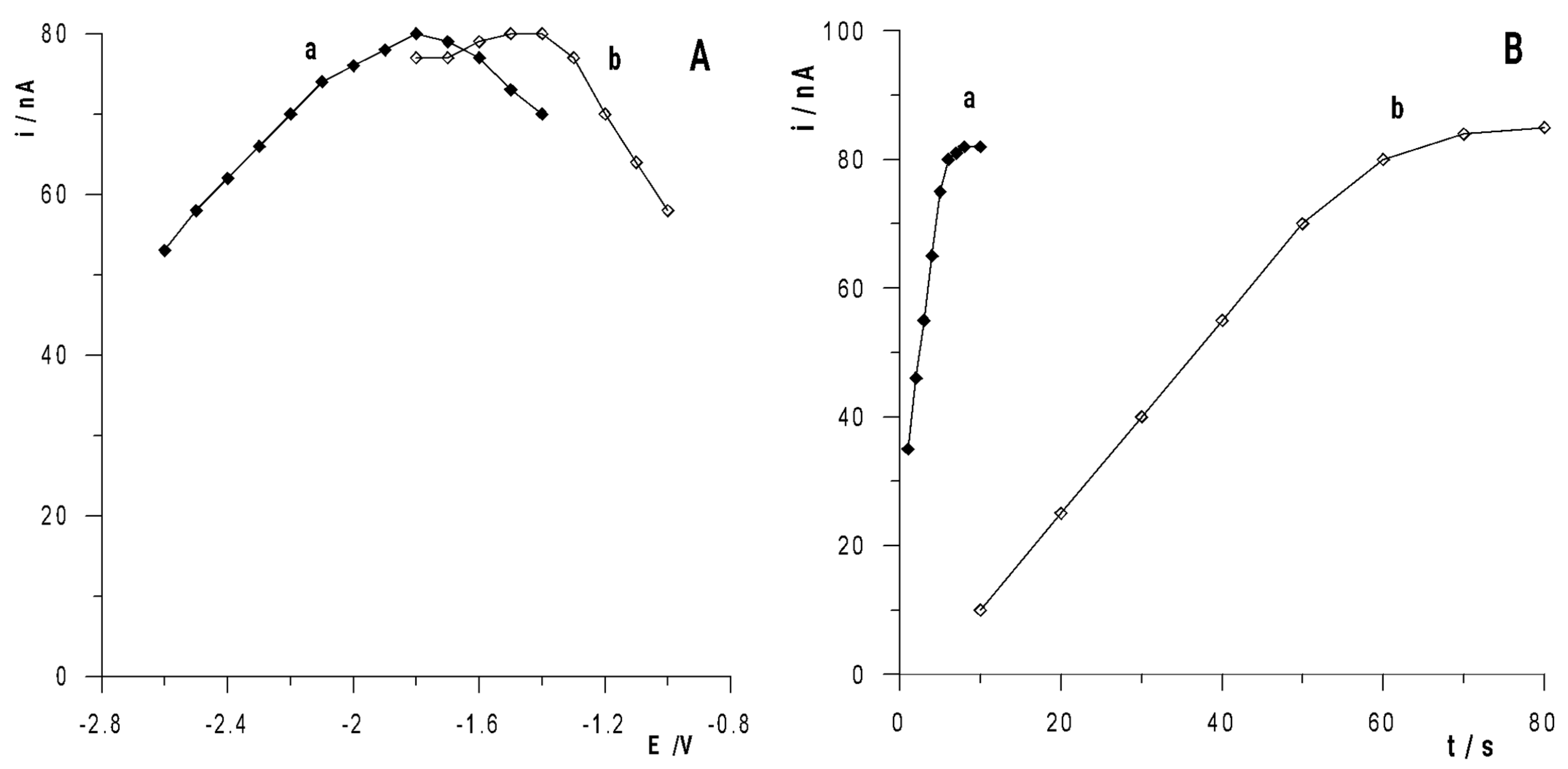
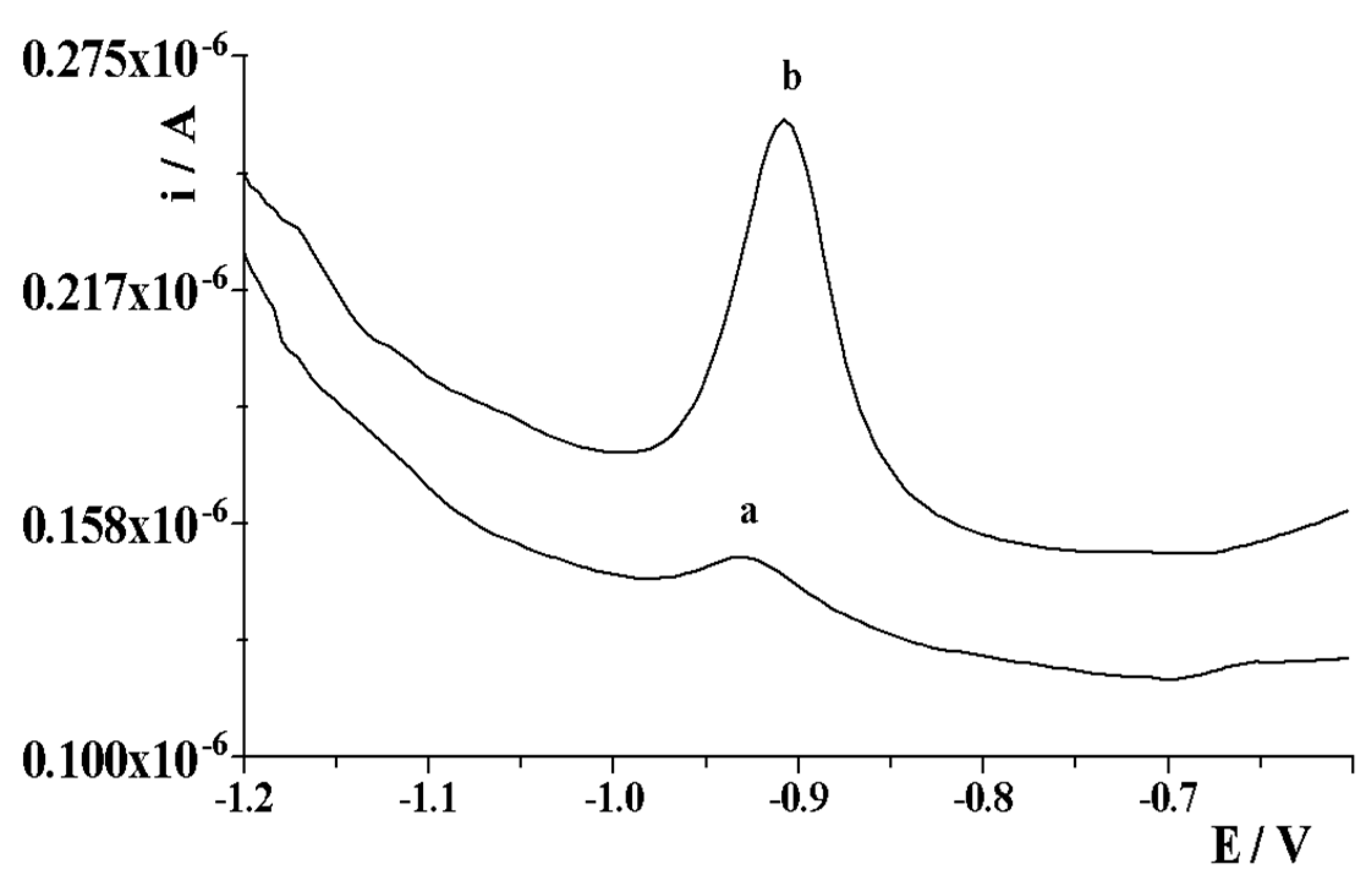
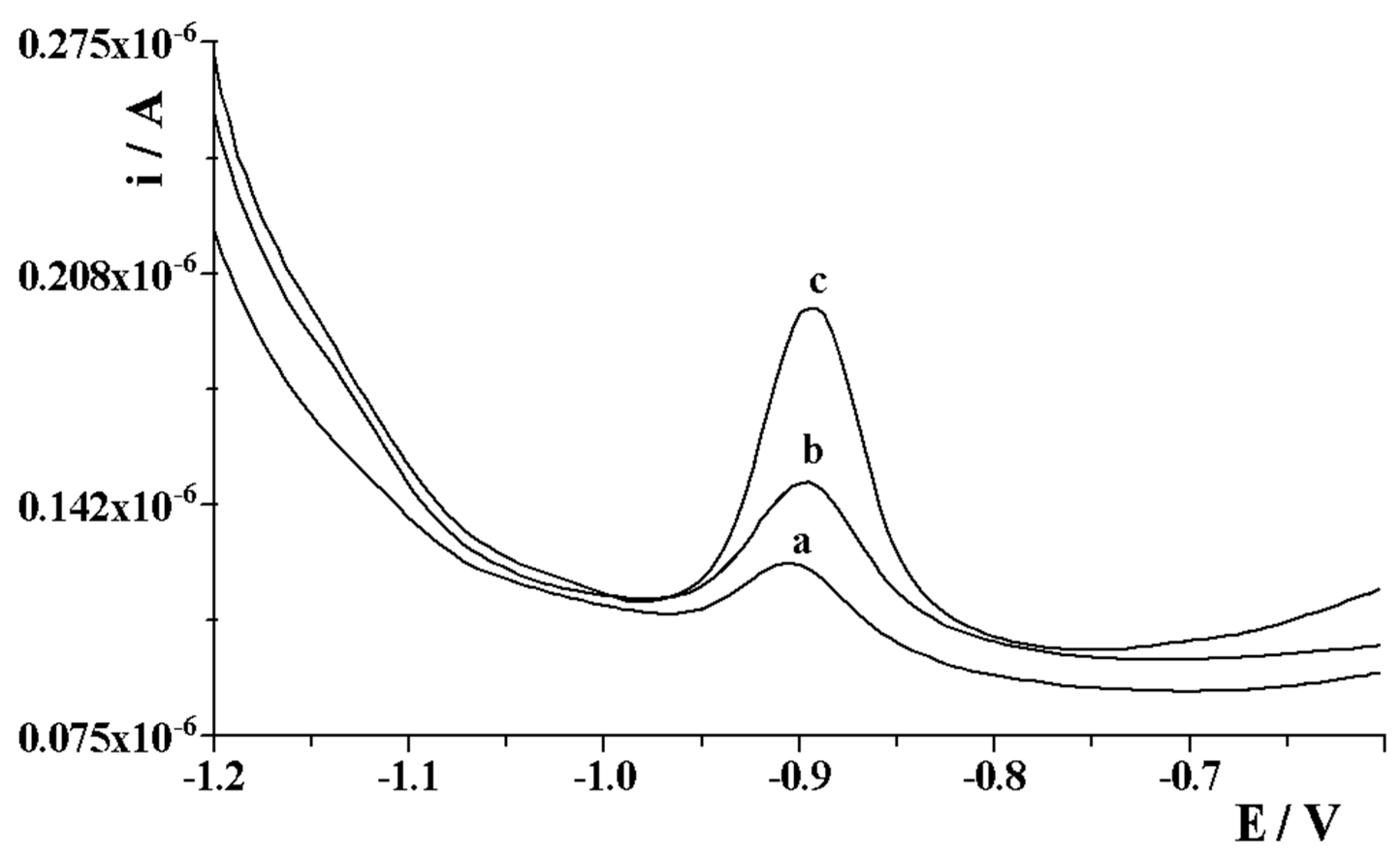
3.1. Activation Conditions of the Bismuth Layer on the Solid Bismuth Microelectrode
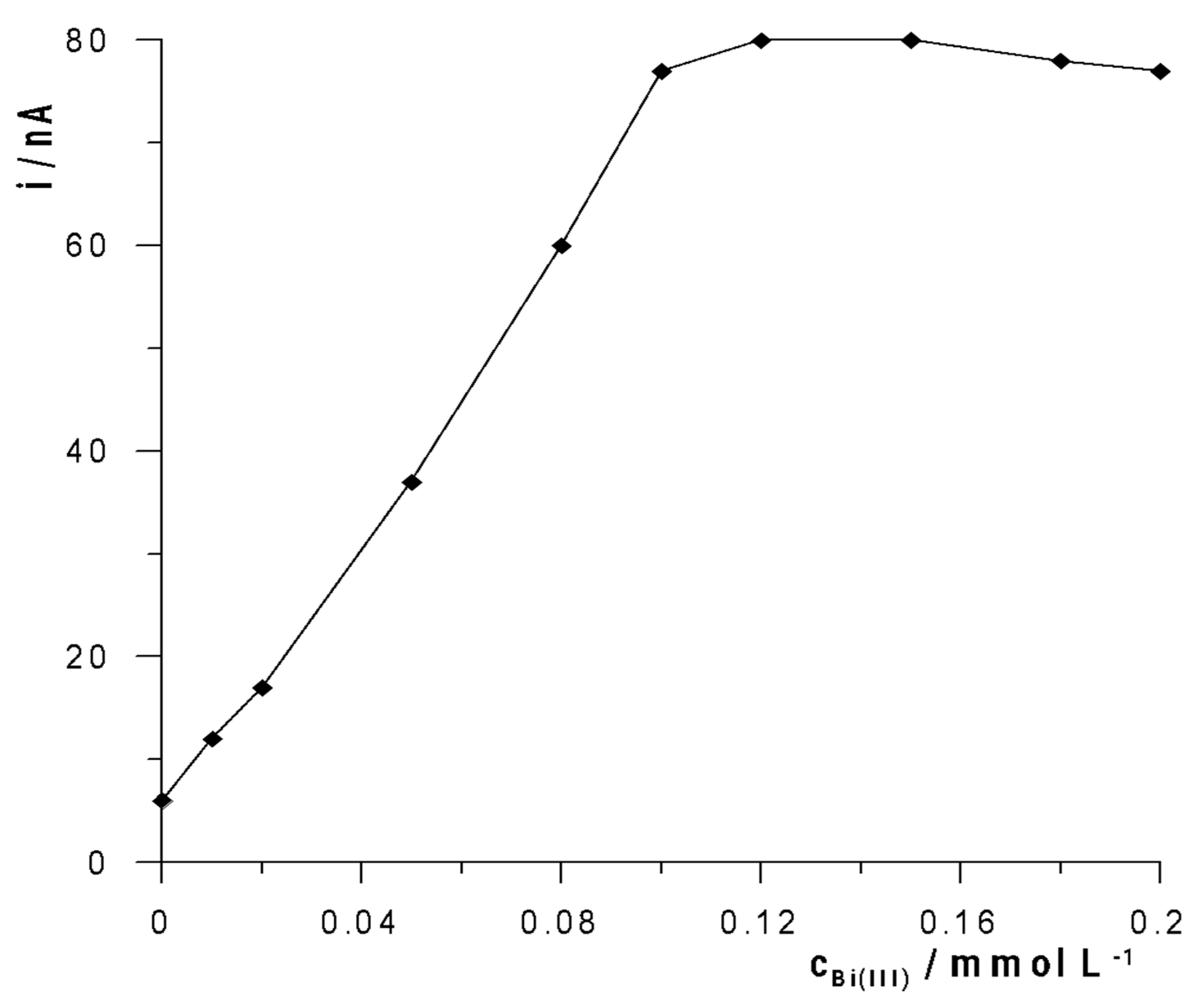
3.2. Effect of Acetate Buffer and Bismuth Concentration
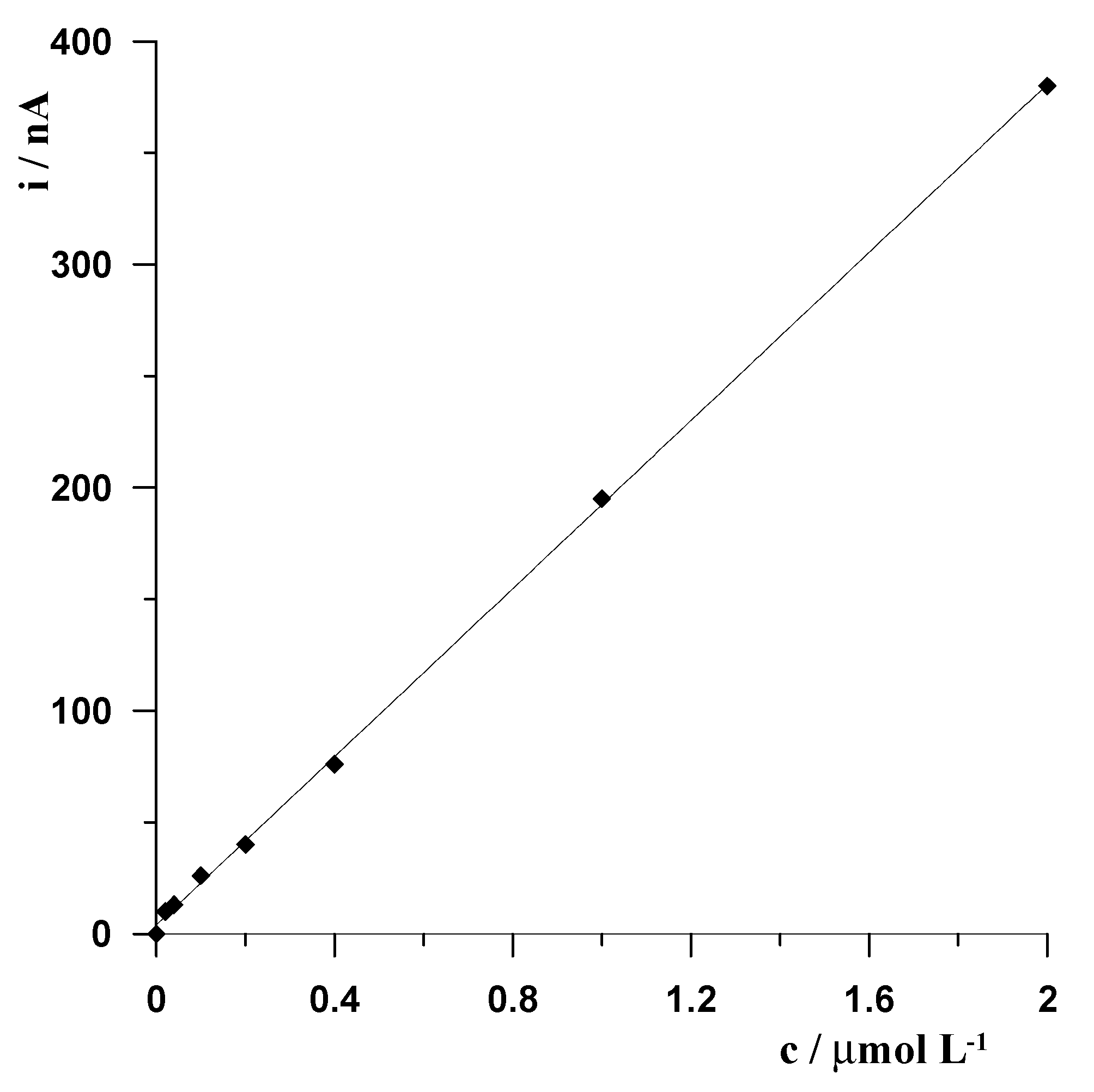
3.3. Analytical Performance
3.4. Stability of Measurement
3.5. Tolerance to Interfering Species
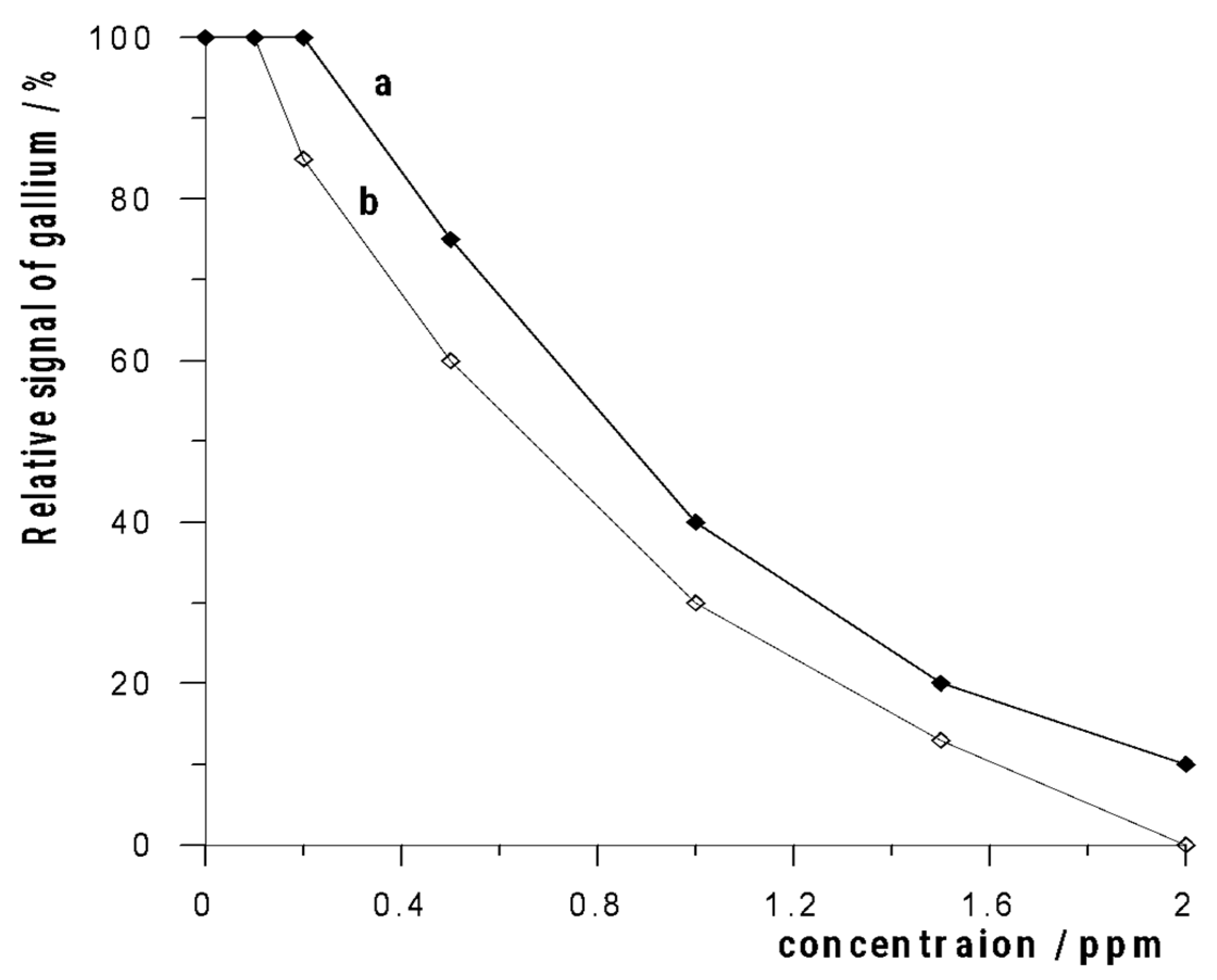
3.6. Analytical Applications
4. Conclusions
- -
- the solid bismuth microelectrode can be a valuable alternative for mercury electrodes for Ga(III) determination by anodic stripping voltammetry;
- -
- thanks to the use of an activated bismuth layer formed in situ on the solid bismuth microelectrode, the sensitivity of the determinations significantly increased compared to the solid bismuth electrode;
- -
- regarding long-term durability, after a minimum of six months of using this sensor, the voltammetric response of gallium remained practically unchanged;
- -
- the developed procedure for the determination of gallium is simple, fast, and does not require expensive equipment;
- -
- as proven, it is possible to directly analyze water environmental samples thanks to the minimizing of the negative effects of the organic matrix.
Author Contributions
Funding
Institutional Review Board Statement
Informed Consent Statement
Data Availability Statement
Conflicts of Interest
References
- Gray, F.; Kramer, D.A.; Bliss, J.D. Gallium and gallium compounds. In Kirk-Othmer Encyclopedia of Chemical Technology; John Wiley & Sons, Inc.: Hoboken, NJ, USA, 2005; Volume 12, pp. 337–364. [Google Scholar]
- Butcher, T.; Brown, T. Gallium. In Critical Metals Handbook; Gunn, G., Ed.; John Wiley & Sons, Inc.: Hoboken, NJ, USA, 2014; pp. 150–176. [Google Scholar]
- Chen, N.F.; Zhong, X.R.; Zhang, M.; Lin, L.Y. Space grown semi-insulating gallium arsenide single crystal and its application. Adv. Space Res. 2002, 29, 537–540. [Google Scholar] [CrossRef]
- Wasmer, K.; Ballif, C.; Pouvreau, C.; Schulz, D.; Michler, J. Dicing of gallium–arsenide high performance laser diodes for industrial applications: Part I. Scratching operation. J. Mater. Proc. Technol. 2008, 198, 105–113. [Google Scholar] [CrossRef]
- Tavallali, H.; Vahdati, P.; Shaabanpur, E. Developing a new method of 4-(2-pyridylazo)-resorcinol immobilization on triacetylcellulose membrane for selective determination of Ga3+ in water samples. Sens. Actuators B Chem. 2011, 159, 154–158. [Google Scholar] [CrossRef]
- White, S.; Shine, J.P. Exposure Potential and Health Impacts of Indium and Gallium, Metals Critical to Emerging Electronics and Energy Technologies. Curr. Environ. Health Rep. 2016, 3, 459–467. [Google Scholar] [CrossRef]
- Chitambar, C.R. Medical Applications and Toxicities of Gallium Compounds. Int. J. Environ. Res. Public Health 2010, 7, 2337–2361. [Google Scholar] [CrossRef] [PubMed] [Green Version]
- Gonzalez, M.J.G.; Renedo, O.D.; Lomillo, M.A.A.; Martinez, M.J.A. Determination of gallium by adsorptive stripping voltammetry. Talanta 2004, 62, 457–462. [Google Scholar] [CrossRef] [PubMed]
- Chen, H.W. Exposure and Health Risk of Gallium, Indium, and Arsenic from Semiconductor Manufacturing Industry Workers. Bull. Environ. Contam. Toxicol. 2007, 78, 5–9. [Google Scholar] [CrossRef] [PubMed]
- Baron-Jaimez, J.; Joya, M.R.; Barba-Ortega, J. Anodic stripping voltammetry—ASV for determination of heavy metals. J. Phys. Conf. Ser. 2013, 466, 012023. [Google Scholar] [CrossRef] [Green Version]
- Wang, J.; Lu, J.; Hocevar, S.B.; Farias, P.A.M. Bismuth-coated carbon electrodes for anodic stripping voltammetry. Anal. Chem. 2000, 72, 3218–3222. [Google Scholar] [CrossRef]
- Wang, J. Stripping analysis at bismuth electrodes: A review. Electroanalysis 2005, 17, 1341–1346. [Google Scholar] [CrossRef]
- Moorhead, E.D.; Davis, P.H. Phase-selective anodic stripping analysis for trace concentrations of gallium. Anal. Chem. 1975, 47, 622–630. [Google Scholar] [CrossRef]
- Udisti, R.; Piccardi, G. Determination of gallium traces by differential pulse anodic stripping voltammetry. Fresenius Z Anal. Chem. 1988, 331, 35–38. [Google Scholar] [CrossRef]
- Bhardwaj, T.K.; Sharma, H.S.; Aggarwal, S.K. Development of anodic stripping voltammetry for determination of gallium in U–Ga alloy. J. Nucl. Mater. 2007, 360, 215–221. [Google Scholar] [CrossRef]
- Piech, R.; Bas, B. Sensitive voltammetric determination of gallium in aluminium materials using renewable mercury film silver based electrode. Int. J. Environ. Anal. Chem. 2011, 91, 410–420. [Google Scholar] [CrossRef]
- Kamat, J.V.; Guin, S.K.; Pillai, J.S.; Aggarwal, S.K. Scope of detection and determination of gallium (III) in industrial ground water by square wave anodic stripping voltammetry on bismuth film electrode. Talanta 2011, 86, 256–265. [Google Scholar] [CrossRef] [PubMed]
- Gȩca, I.; Ochab, M.; Korolczuk, M. Anodic Stripping Voltammetry of Tl(I) Determination with the Use of a Solid Bismuth Microelectrode. J. Electrochem. Soc. 2020, 167, 086506. [Google Scholar] [CrossRef]
- Grabarczyk, M.; Adamczyk, M.; Wlazłowska, E. The Use of a Solid Bismuth Microelectrode for Vanadium Quantification by Adsorptive Stripping Voltammetry in Environmental Water Samples. Molecules 2022, 27, 2168. [Google Scholar] [CrossRef] [PubMed]
- Adamczyk, M.; Grabarczyk, M. Application of a Solid Bismuth Microelectrode in an Adsorptive Stripping Voltammetric Procedure of Trace Tin Quantification. J. Electrochem. Soc. 2022, 169, 016515. [Google Scholar] [CrossRef]
- Gęca, I.; Korolczuk, M. Sensitive Determination of Folic Acid using a Solid Bismuth Microelectrode by Adsorptive Stripping Voltammetry. Electroanalysis 2020, 32, 496–502. [Google Scholar] [CrossRef]
- Bernardellia, J.K.B.; Lapollib, F.R.; da Silva Cruza, C.M.G.; Floriano, J.B. Determination of Zinc and Cadmium with Characterized Electrodes of Carbon and Polyurethane Modified by a Bismuth Film. Mater. Res. 2011, 14, 366–371. [Google Scholar] [CrossRef]
- Bobrowski, A.; Królicka, A.; Zarębski, J. Morphology and Electrochemical Properties of the Bismuth Film Electrode Ex Situ Electrochemically Plated from Perchloric Acid. Electroanalysis 2010, 22, 1421–1427. [Google Scholar] [CrossRef]
- Adamczyk, M.; Grabarczyk, M.; Leszko, W. A voltammetric approach to the quantification of tungsten in environmental waters using a solid bismuth microelectrode. Measurement 2022, 194, 111089. [Google Scholar] [CrossRef]
- Bobrowski, A.; Kapturski, P.; Zarębski, J.; Dominik, J.; Vignati, A.L.D. Catalytic Adsorptive Stripping Voltammetric Determination of Chromium(VI) in Overlying and Interstitial Waters Isolated from Sediments Contaminated by Tannery Waste. Anal. Lett. 2012, 45, 495–507. [Google Scholar] [CrossRef]
- Grabarczyk, M.; Koper, A. Selective, sensitive and economical method for the adsorptive voltammetric determination of trace amounts of Mo(VI) in organic matter rich environmental samples. Talanta 2011, 84, 393–399. [Google Scholar] [CrossRef]
- Arino, C.; Serrano, N.; Diaz-Cruz, J.M.; Esteban, M. Voltammetric determination of metal ions beyond mercury electrodes. A review. Anal. Chim. Acta 2017, 990, 11–53. [Google Scholar] [CrossRef]


| Sample | Ga(III) Added (nmol L−1) | Ga(III) Found (nmol L−1) | Recovery (%) | RSD (n = 5) (%) |
|---|---|---|---|---|
| Certified reference material SPS-WW1 waste water | 100 | 92.4 | 92.4 | 6.2 |
| 400 | 382.4 | 95.6 | 4.6 | |
| Certified reference material SPS-SW2 surface water | 50 | 52.0 | 104.0 | 3.2 |
| 200 | 211 | 105.5 | 4.8 | |
| Bystrzyca river water | 100 | 94.4 | 94.4 | 5.8 |
| 400 | 384.8 | 96.2 | 5.3 | |
| Tap water | 50 | 51.5 | 103.0 | 6.4 |
| 200 | 195 | 97.5 | 4.6 |
Publisher’s Note: MDPI stays neutral with regard to jurisdictional claims in published maps and institutional affiliations. |
© 2022 by the authors. Licensee MDPI, Basel, Switzerland. This article is an open access article distributed under the terms and conditions of the Creative Commons Attribution (CC BY) license (https://creativecommons.org/licenses/by/4.0/).
Share and Cite
Grabarczyk, M.; Wlazlowska, E. An Activated Bismuth Layer Formed In Situ on a Solid Bismuth Microelectrode for Electrochemical Sensitive Determination of Ga(III). Membranes 2022, 12, 1267. https://doi.org/10.3390/membranes12121267
Grabarczyk M, Wlazlowska E. An Activated Bismuth Layer Formed In Situ on a Solid Bismuth Microelectrode for Electrochemical Sensitive Determination of Ga(III). Membranes. 2022; 12(12):1267. https://doi.org/10.3390/membranes12121267
Chicago/Turabian StyleGrabarczyk, Malgorzata, and Edyta Wlazlowska. 2022. "An Activated Bismuth Layer Formed In Situ on a Solid Bismuth Microelectrode for Electrochemical Sensitive Determination of Ga(III)" Membranes 12, no. 12: 1267. https://doi.org/10.3390/membranes12121267