
Numerical Simulation of Continuous Extraction of Li+ from High Mg2+/Li+ Ratio Brines Based on Free Flow Ion Concentration Polarization Microfluidic System

Abstract
:1. Introduction
2. Method
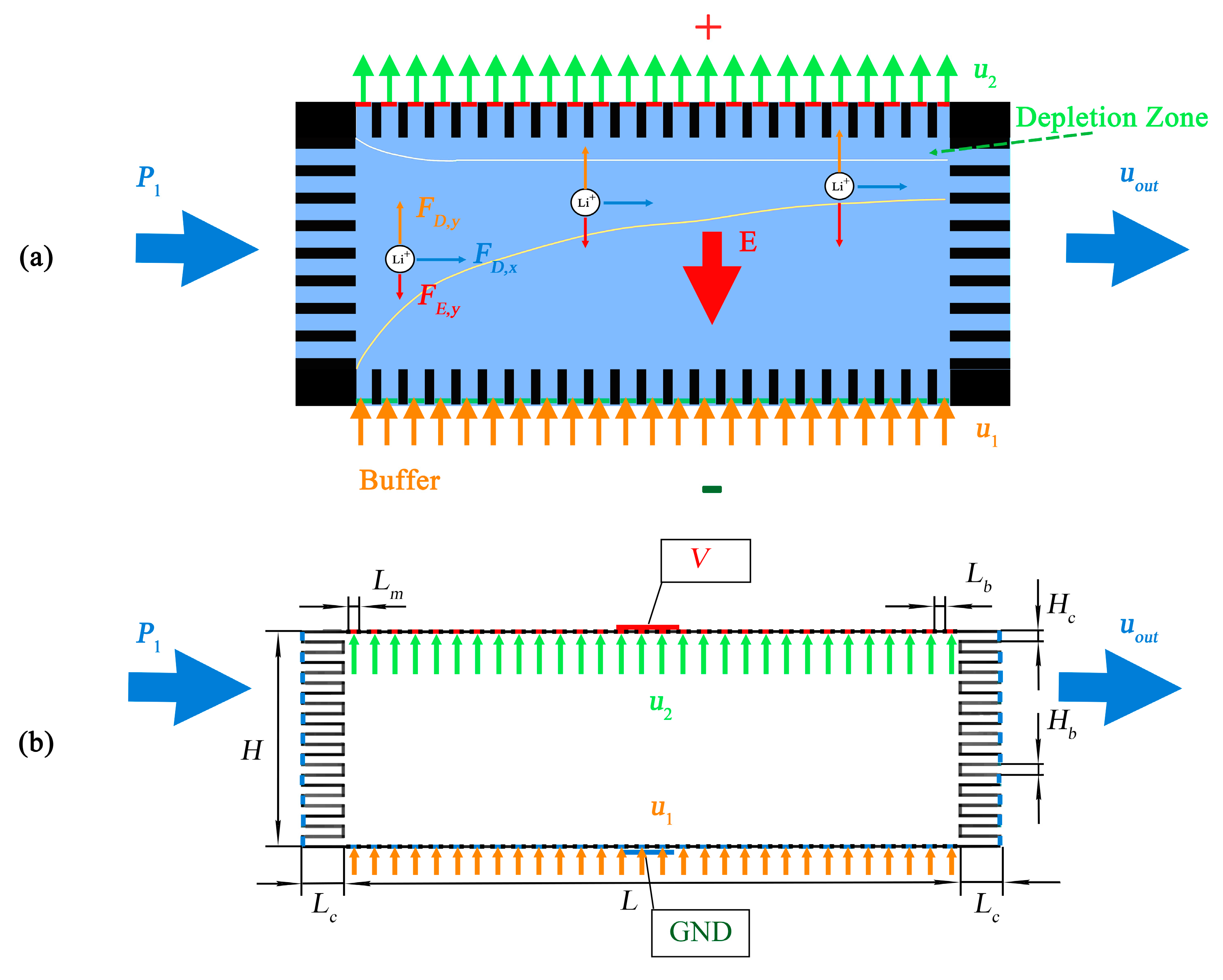
2.1. Physical Setup
2.2. Simulation Model
2.3. Governing Equations
2.4. Boundary Conditions
2.5. Numerical Methods
3. Results and Discussions
3.1. Effect of the Voltage
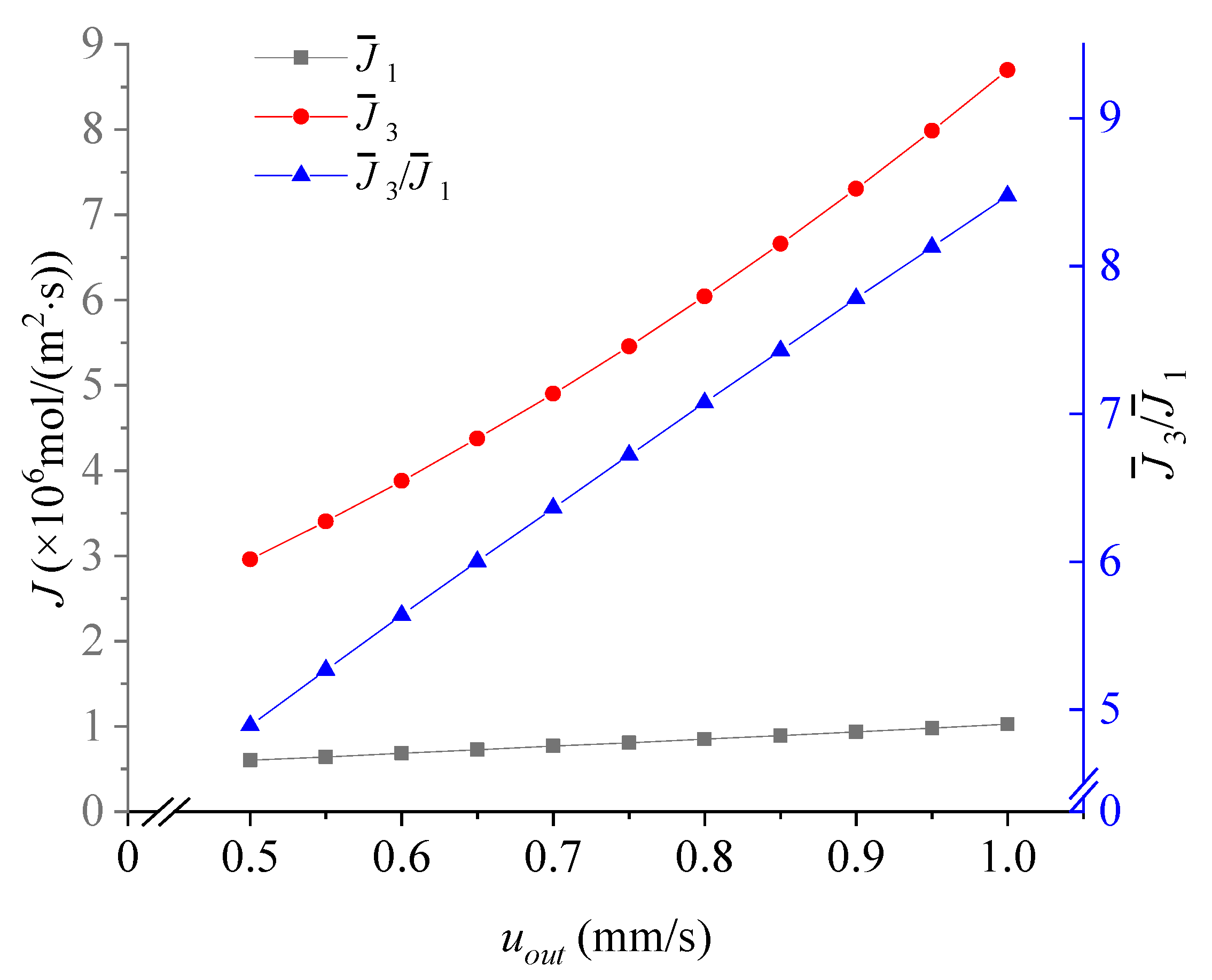
3.2. Effect of the Velocity uout
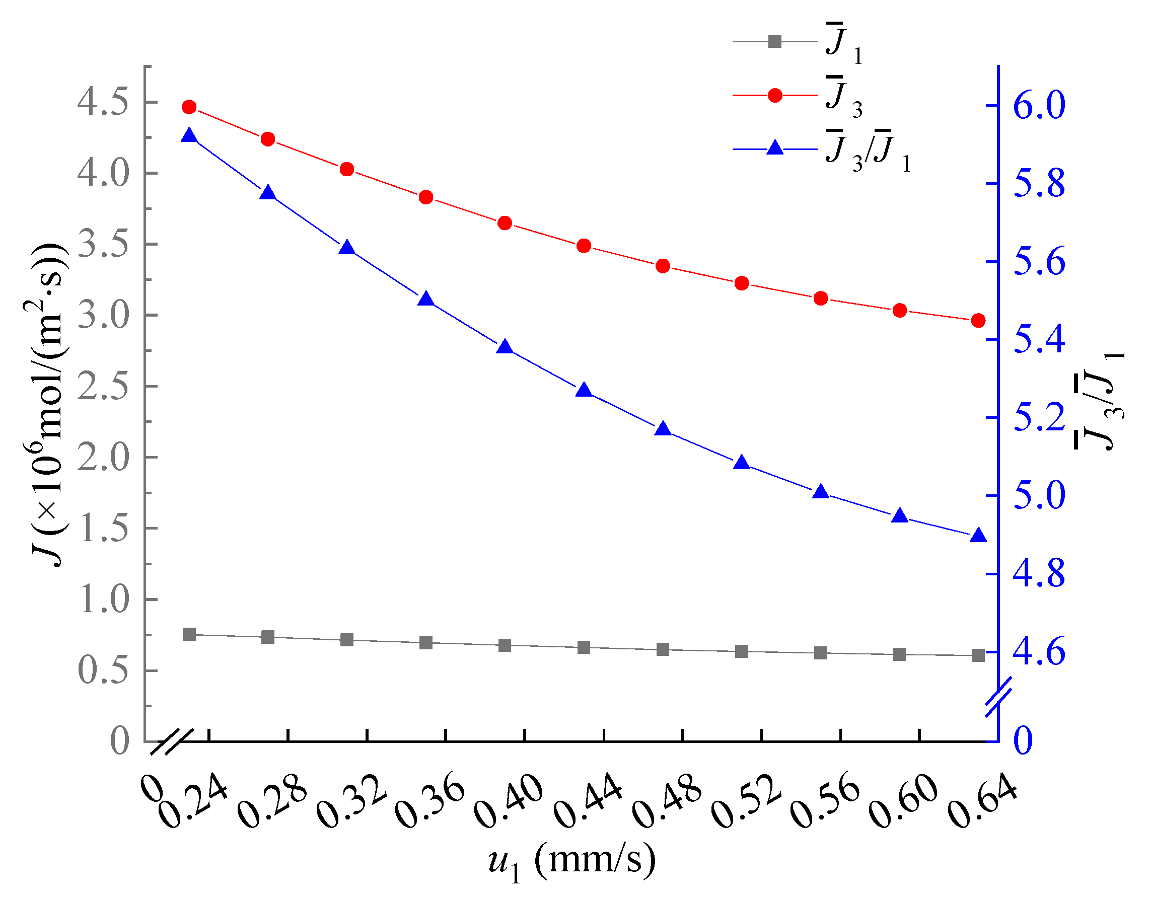
3.3. Effect of the Velocity u1
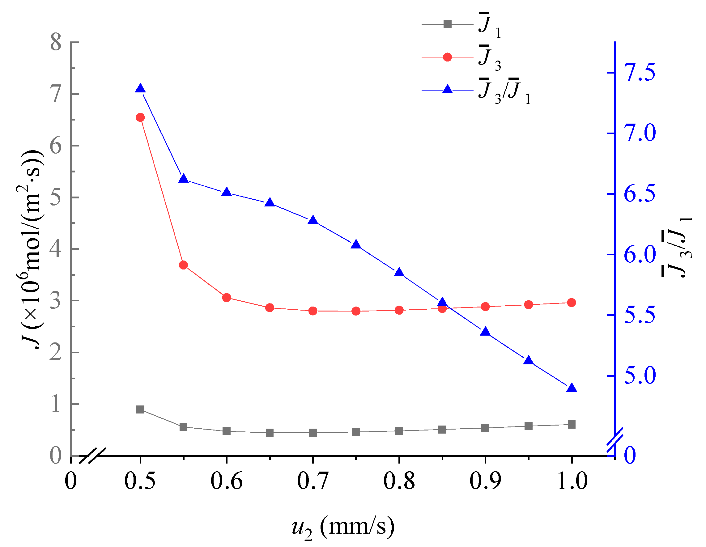
3.4. Effect of the Velocity u2
3.5. Advantages and Limitations
4. Conclusions
Author Contributions
Funding
Institutional Review Board Statement
Data Availability Statement
Conflicts of Interest
References
- Averill, W.A.; Olson, D.L. A Review of extractive processes for lithium from ores and brines. In Lithium Needs and Resources; Penner, S.S., Ed.; Pergamon: Oxford, UK, 1978; pp. 305–313. ISBN 978-0-08-022733-7. [Google Scholar]
- Kesler, S.E.; Gruber, P.W.; Medina, P.A.; Keoleian, G.A.; Everson, M.P.; Wallington, T.J. Global Lithium resources: Relative Importance of pegmatite, brine and other deposits. Ore Geol. Rev. 2012, 48, 55. [Google Scholar] [CrossRef]
- Swain, B. Recovery and recycling of lithium: A review. Sep. Purif. Technol. 2017, 172, 388–403. [Google Scholar] [CrossRef]
- Yu, J.; Zheng, M.; Wu, Q.; Nie, Z.; Bu, L. Extracting lithium from Tibetan Dangxiong Tso Salt Lake of carbonate type by using geothermal salinity-gradient solar pond. Sol. Energy 2015, 115, 133–144. [Google Scholar] [CrossRef]
- An, J.W.; Kang, D.J.; Tran, K.T.; Kim, M.J.; Lim, T.; Tran, T. Recovery of lithium from Uyuni salar brine. Hydrometallurgy 2012, 117, 64–70. [Google Scholar] [CrossRef]
- Xu, Z.; Zhang, H.; Wang, R.; Gui, W.; Liu, G.; Yang, Y. Systemic and direct production of battery-grade lithium carbonate from a saline lake. Ind. Eng. Chem. Res. 2014, 53, 16502–16507. [Google Scholar] [CrossRef]
- Zhang, Y.; Hu, Y.; Wang, L.; Sun, W. Systematic review of lithium extraction from salt-lake brines via precipitation approaches. Miner. Eng. 2019, 139, 105868. [Google Scholar] [CrossRef]
- Li, X.; Mo, Y.; Qing, W.; Shao, S.; Tang, C.Y.; Li, J. Membrane-based technologies for lithium recovery from water lithium resources: A review. J. Memb. Sci. 2019, 591, 117317. [Google Scholar] [CrossRef]
- Xiao, G.; Tong, K.; Zhou, L.; Xiao, J.; Sun, S.; Li, P.; Yu, J. Adsorption and Desorption behavior of lithium ion in spherical PVC–MnO2 Ion sieve. Ind. Eng. Chem. Res. 2012, 51, 10921–10929. [Google Scholar] [CrossRef]
- Xu, W.; He, L.; Zhao, Z. Lithium extraction from high Mg/Li brine via electrochemical intercalation/de-intercalation system using LiMn2O4 materials. Desalination 2021, 503, 114935. [Google Scholar] [CrossRef]
- Li, X.; Chao, Y.; Chen, L.; Chen, W.; Luo, J.; Wang, C.; Wu, P.; Li, H.; Zhu, W. Taming wettability of lithium ion sieve via different TiO2 precursors for effective Li recovery from aqueous lithium resources. Chem. Eng. J. 2020, 392, 123731. [Google Scholar] [CrossRef]
- Nie, X.Y.; Sun, S.Y.; Sun, Z.; Song, X.; Yu, J.G. Ion-fractionation of lithium ions from magnesium ions by electrodialysis using monovalent selective ion-exchange membranes. Desalination 2017, 403, 128–135. [Google Scholar] [CrossRef]
- Yang, G.; Shi, H.; Liu, W.; Xing, W.; Xu, N. Investigation of Mg2+/Li+ separation by nanofiltration. Chin. J. Chem. Eng. 2011, 19, 586–591. [Google Scholar] [CrossRef]
- Li, Y.; Zhao, Y.J.; Wang, H.; Wang, M. The application of nanofiltration membrane for recovering lithium from salt lake brine. Desalination 2019, 468, 114081. [Google Scholar] [CrossRef]
- Flexer, V.; Baspineiro, C.F.; Galli, C.I. Lithium recovery from brines: A vital raw material for green energies with a potential environmental impact in its mining and processing. Sci. Total Environ. 2018, 639, 1188–1204. [Google Scholar] [CrossRef]
- Gao, F.; Zheng, M.-P.; Nie, Z.; Liu, J.-H.; Song, P.-S. Brine lithium resource in the salt lake and advances in its exploitation. Acta Geosci. Sin. 2011, 32, 483–492. [Google Scholar]
- Wang, J.; Yang, S.; Bai, R.; Chen, Y.; Zhang, S. Lithium Recovery from the Mother Liquor Obtained in the Process of Li2CO3 Production. Ind. Eng. Chem. Res. 2019, 58, 1363–1372. [Google Scholar] [CrossRef]
- Gu, D.; Sun, W.; Han, G.; Cui, Q.; Wang, H. Lithium ion sieve synthesized via an improved solid state method and adsorption performance for West Taijinar Salt Lake brine. Chem. Eng. J. 2018, 350, 474–483. [Google Scholar] [CrossRef]
- Ji, P.-Y.; Ji, Z.-Y.; Chen, Q.-B.; Liu, J.; Zhao, Y.-Y.; Wang, S.-Z.; Li, F.; Yuan, J.-S. Effect of coexisting ions on recovering lithium from high Mg2+/Li+ ratio brines by selective-electrodialysis. Sep. Purif. Technol. 2018, 207, 1–11. [Google Scholar] [CrossRef]
- Ji, Z.Y.; Zhao, M.Y.; Zhao, Y.Y.; Liu, J.; Peng, J.L.; Yuan, J.S. Lithium extraction process on spinel-type LiMn2O4 and characterization based on the hydrolysis of sodium persulfate. Solid State Ion. 2017, 301, 116–124. [Google Scholar] [CrossRef]
- Guo, X.; Hu, S.; Wang, C.; Duan, H.; Xiang, X. Highly Efficient Separation of Magnesium and Lithium and High-Valued Utilization of Magnesium from salt lake brine by a reaction-coupled separation technology. Ind. Eng. Chem. Res. 2018, 57, 6618–6626. [Google Scholar] [CrossRef]
- Ji, Z.Y.; Chen, Q.B.; Yuan, J.S.; Liu, J.; Zhao, Y.Y.; Feng, W.X. Preliminary study on recovering lithium from high Mg2+/Li+ ratio brines by electrodialysis. Sep. Purif. Technol. 2017, 172, 168–177. [Google Scholar] [CrossRef]
- Wang, Y.C.; Stevens, A.L.; Han, J. Million-fold preconcentration of proteins and peptides by nanofluidic filter. Anal. Chem. 2005, 77, 4293–4299. [Google Scholar] [CrossRef]
- Kim, S.J.; Li, L.D.; Han, J. Amplified electrokinetic response by concentration polarization near nanofluidic channel. Langmuir 2009, 25, 7759–7765. [Google Scholar] [CrossRef] [Green Version]
- Mani, A.; Zangle, T.A.; Santiago, J.G. On the propagation of concentration polarization from microchannel-nanochannel interfaces Part I: Analytical model and characteristic analysis. Langmuir 2009, 25, 3898–3908. [Google Scholar] [CrossRef] [PubMed] [Green Version]
- Kim, S.J.; Song, Y.A.; Han, J. Nanofluidic concentration devices for biomolecules utilizing ion concentration polarization: Theory, fabrication, and applications. Chem. Soc. Rev. 2010, 39, 912–922. [Google Scholar] [CrossRef] [Green Version]
- Kim, S.J.; Ko, S.H.; Kang, K.H.; Han, J. Direct seawater desalination by ion concentration polarization. Nat. Nanotechnol. 2010, 5, 297–301. [Google Scholar] [CrossRef]
- Hlushkou, D.; Knust, K.N.; Crooks, R.M.; Tallarek, U. Numerical simulation of electrochemical desalination. J. Phys. Condens. Matter 2016, 28, 194001. [Google Scholar] [CrossRef] [PubMed] [Green Version]
- Gong, L.; Ouyang, W.; Li, Z.; Han, J. Force fields of charged particles in micro-nanofluidic preconcentration systems. AIP Adv. 2017, 7, 125020. [Google Scholar] [CrossRef] [Green Version]
- Ouyang, W.; Li, Z.; Han, J. Pressure-Modulated selective electrokinetic trapping for direct enrichment, purification, and detection of nucleic acids in human serum. Anal. Chem. 2018, 90, 11366–11375. [Google Scholar] [CrossRef]
- Gong, L.; Ouyang, W.; Li, Z.; Han, J. Direct numerical simulation of continuous lithium extraction from high Mg2+/Li+ ratio brines using microfluidic channels with ion concentration polarization. J. Membr. Sci. 2018, 556, 34–41. [Google Scholar] [CrossRef] [PubMed]
- Gong, L.; Li, Z.; Han, J. Numerical simulation of continuous extraction of highly concentrated Li+ from high Mg2+/Li+ ratio brines in an ion concentration polarization-based microfluidic system. Sep. Purif. Technol. 2019, 217, 174–182. [Google Scholar] [CrossRef]
- Papadimitriou, V.A.; Segerink, L.I.; Eijkel, J.C.T. Free Flow ion concentration polarization focusing (FF-ICPF). Anal. Chem. 2020, 92, 4866–4874. [Google Scholar] [CrossRef] [Green Version]
- Ouyang, W.; Ye, X.; Li, Z.; Han, J. Deciphering ion concentration polarization-based electrokinetic molecular concentration at the micro-nanofluidic interface: Theoretical limits and scaling laws. Nanoscale 2018, 10, 15187–15194. [Google Scholar] [CrossRef] [Green Version]
- Vanýsek, P. Ionic Conductivity and Diffusion at Infinite Dilution, 1992/93 ed.; CRC Press: Boca Raton, FL, USA, 1992. [Google Scholar]
- Jiang, J.; Tang, J.; Al-Anzi, B.; Han, J.; Li, Z. On the validity of ion selective membrane simplification in concentration polarization. AIP Adv. 2021, 11, 035116. [Google Scholar] [CrossRef]
- Rubinstein, I.; Zaltzman, B. Equilibrium electroconvective instability. Phys. Rev. Lett. 2015, 114, 114502. [Google Scholar] [CrossRef] [Green Version]
- Nanthasurasak, P.; Cabot, J.M.; See, H.H.; Guijt, R.M.; Breadmore, M.C. Electrophoretic separations on paper: Past, present, and future—A review. Anal. Chim. Acta 2017, 985, 7–23. [Google Scholar] [CrossRef]
- Kim, S.J.; Ko, S.H.; Kwak, R.; Posner, J.D.; Kang, K.H.; Han, J. Multi-vortical flow inducing electrokinetic instability in ion concentration polarization layer. Nanoscale 2012, 4, 7406–7410. [Google Scholar] [CrossRef]
- Druzgalski, C.L.; Andersen, M.B.; Mani, A. Direct numerical simulation of electroconvective instability and hydrodynamic chaos near an ion-selective surface. Phys. Fluids 2013, 25, 110804. [Google Scholar] [CrossRef]
- Karatay, E.; Druzgalski, C.L.; Mani, A. Simulation of chaotic electrokinetic transport: Performance of commercial software versus custom-built direct numerical simulation codes. J. Colloid Interface Sci. 2015, 446, 67–76. [Google Scholar] [CrossRef] [PubMed]
- Park, S.; Kwak, R. Microscale electrodeionization: In situ concentration profiling and flow visualization. Water Res. 2020, 170, 115310. [Google Scholar] [CrossRef] [PubMed]
- Phan, D.T.; Jin, L.; Wustoni, S.; Chen, C.H. Buffer-free integrative nanofluidic device for real-time continuous flow bioassays by ion concentration polarization. Lab Chip 2018, 18, 574–584. [Google Scholar] [CrossRef] [PubMed]
- Zhang, C.; Mu, Y.; Zhao, S.; Zhang, W.; Wang, Y. Lithium extraction from synthetic brine with high Mg2+/Li+ ratio using the polymer inclusion membrane. Desalination 2020, 496, 114710. [Google Scholar] [CrossRef]
- Yoon, J.; Do, V.Q.; Pham, V.S.; Han, J. Return flow ion concentration polarization desalination: A new way to enhance electromembrane desalination. Water Res. 2019, 159, 501–510. [Google Scholar] [CrossRef] [PubMed]
- De Valença, J.; Jõgi, M.; Wagterveld, R.M.; Karatay, E.; Wood, J.A.; Lammertink, R.G.H. Confined Electroconvective vortices at structured ion exchange membranes. Langmuir 2018, 34, 2455–2463. [Google Scholar] [CrossRef] [PubMed] [Green Version]
- Liu, W.; Gong, L.; Zhu, Y.; Li, Z. Augmented electroosmotic flow and simultaneous desalination in microchannels embedded with permselective membranes. Sci. Sin. Technol. 2018, 48, 17–24. [Google Scholar] [CrossRef]


| Index i | Species | Diffusion Coefficient Di (×10−9 m2/s) | Electrophoretic Mobility μi (×10−8 m2/V⋅s) |
|---|---|---|---|
| 1 | Li+ | 1.029 | 3.98 |
| 2 | Na+ | 1.334 | 5.152 |
| 3 | Mg2+ | 0.706 | 7.563 |
| 4 | K+ | 1.957 | 5.457 |
| 5 | Cl− | 2.032 | 7.853 |
Publisher’s Note: MDPI stays neutral with regard to jurisdictional claims in published maps and institutional affiliations. |
© 2021 by the authors. Licensee MDPI, Basel, Switzerland. This article is an open access article distributed under the terms and conditions of the Creative Commons Attribution (CC BY) license (https://creativecommons.org/licenses/by/4.0/).
Share and Cite
Zhang, D.; Zhang, X.; Xing, L.; Li, Z. Numerical Simulation of Continuous Extraction of Li+ from High Mg2+/Li+ Ratio Brines Based on Free Flow Ion Concentration Polarization Microfluidic System. Membranes 2021, 11, 697. https://doi.org/10.3390/membranes11090697
Zhang D, Zhang X, Xing L, Li Z. Numerical Simulation of Continuous Extraction of Li+ from High Mg2+/Li+ Ratio Brines Based on Free Flow Ion Concentration Polarization Microfluidic System. Membranes. 2021; 11(9):697. https://doi.org/10.3390/membranes11090697
Chicago/Turabian StyleZhang, Dongxiang, Xianglei Zhang, Leilei Xing, and Zirui Li. 2021. "Numerical Simulation of Continuous Extraction of Li+ from High Mg2+/Li+ Ratio Brines Based on Free Flow Ion Concentration Polarization Microfluidic System" Membranes 11, no. 9: 697. https://doi.org/10.3390/membranes11090697