
Synthesis of ZIF-11 Membranes: The Influence of Preparation Technique and Support Type

 , and
, and
Abstract
:
1. Introduction
2. Materials and Methods
2.1. Materials
2.2. Synthesis Methods
2.2.1. Synthesis of ZIF-11 Seed Crystals
2.2.2. Membrane Supports
2.2.3. Cleaning of the Membrane Supports
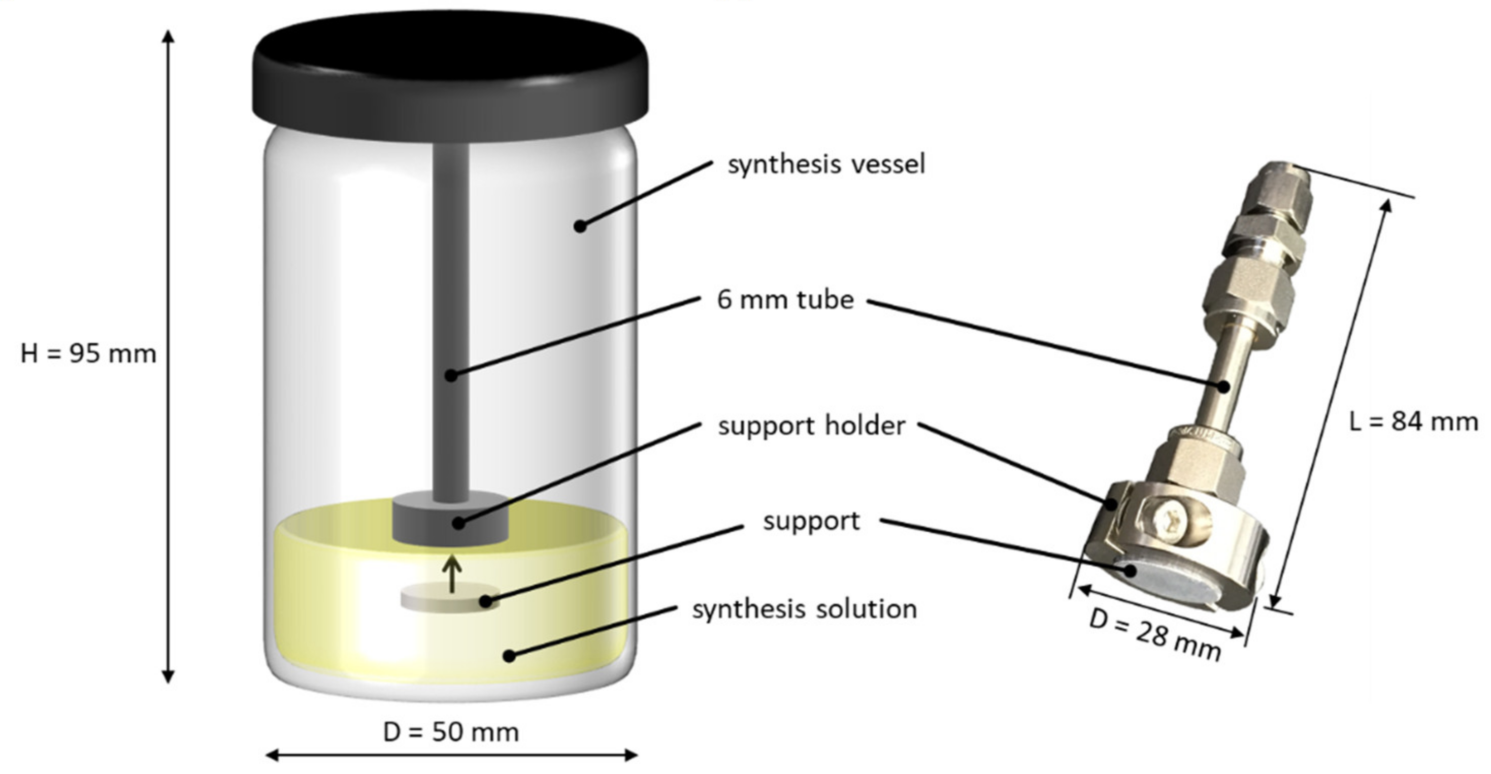
2.2.4. In Situ Synthesis of ZIF-11 Membranes
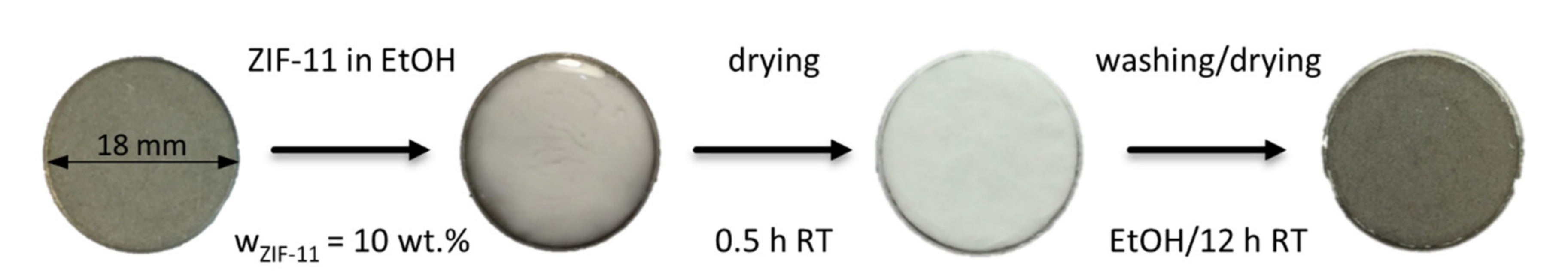
2.2.5. Seeding and Secondary Growth of ZIF-11 Membranes
2.2.6. Seeding Procedures
2.3. Characterization Methods
2.3.1. X-ray Diffraction (XRD)
2.3.2. ZIF-11 Loading
2.3.3. Scanning Electron Microscopy (SEM)
2.3.4. Permeance Measurements
3. Results and Discussion
3.1. In Situ and Multiple In Situ Crystallization
3.1.1. Influence of Synthesis Time on ZIF-11 Layer Formation
3.1.2. Influence of the Number of Synthesis Steps on Layer Formation
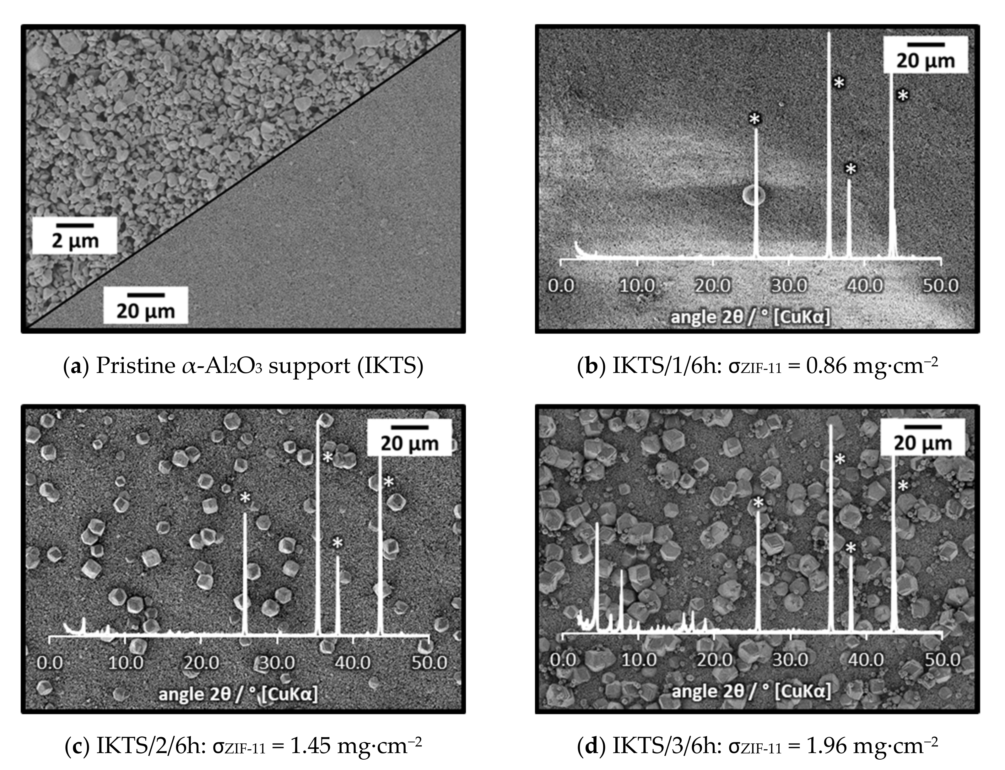
3.1.3. Influence of Support Material and Porosity on Layer Formation
3.2. Seeding and Secondary Growth
3.2.1. Preparation of Seed Crystals
3.2.2. Drop Seeding and Secondary Growth
3.2.3. Doctor Blade Seeding, Rub Seeding, and Secondary Growth
4. Conclusions
Supplementary Materials
Author Contributions
Funding
Acknowledgments
Conflicts of Interest
References
- Aceituno Melgar, V.M.; Kim, J.; Othman, M.R. Zeolitic imidazolate framework membranes for gas separation: A review of synthesis methods and gas separation performance. J. Ind. Eng. Chem. 2015, 28, 1–15. [Google Scholar] [CrossRef]
- Shah, M.; McCarthy, M.C.; Sachdeva, S.; Lee, A.K.; Jeong, H.-K. Current Status of Metal–Organic Framework Membranes for Gas Separations: Promises and Challenges. Ind. Eng. Chem. Res. 2011, 51, 2179–2199. [Google Scholar] [CrossRef]
- Mirqasemi, M.S.; Homayoonfal, M.; Rezakazemi, M. Zeolitic imidazolate framework membranes for gas and water purification. Environ. Chem. Lett. 2020, 18. [Google Scholar] [CrossRef]
- Park, K.S.; Ni, Z.; Cote, A.P.; Choi, J.Y.; Huang, R.; Uribe-Romo, F.J.; Chae, H.K.; O’Keeffe, M.; Yaghi, O.M. Exceptional chemical and thermal stability of zeolitic imidazolate frameworks. Proc. Natl. Acad. Sci. USA 2006, 103, 10186–10191. [Google Scholar] [CrossRef] [PubMed] [Green Version]
- Banerjee, R.; Phan, A.; Wang, B.; Knobler, C.; Furukawa, H.; O’Keeffe, M.; Yaghi, O.M. High-Throughput Synthesis of Zeolitic Imidazolate Frameworks and Application to CO2 Capture. Science 2008, 319, 939–943. [Google Scholar] [CrossRef] [PubMed]
- Morris, W.; Doonan, C.J.; Furukawa, H.; Banerjee, R.; Yaghi, O.M. Crystals as Molecules: Postsynthesis Covalent Functionalization of Zeolitic Imidazolate Frameworks. J. Am. Chem. Soc. 2008, 130, 12626–12627. [Google Scholar] [CrossRef] [PubMed]
- Phan, A.; Doonan, C.J.; Uribe-Romo, F.J.; Knobler, C.B.; O’Keeffe, M.; Yaghi, O.M. Synthesis, Structure, and Carbon Dioxide Capture Properties of Zeolitic Imidazolate Frameworks. Acc. Chem. Res. 2009, 43, 58–67. [Google Scholar] [CrossRef]
- Rowsell, J.L.C.; Yaghi, O.M. Metal–organic frameworks: A new class of porous materials. Microporous Mesoporous Mater. 2004, 73, 3–14. [Google Scholar] [CrossRef]
- Yao, J.; Dong, D.; Li, D.; He, L.; Xu, G.; Wang, H. Contra-diffusion synthesis of ZIF-8 films on a polymer substrate. Chem. Commun. 2011, 47, 2559–2561. [Google Scholar] [CrossRef]
- He, M.; Yao, J.; Li, L.; Zhong, Z.; Chen, F.; Wang, H. Aqueous solution synthesis of ZIF-8 films on a porous nylon substrate by contra-diffusion method. Microporous Mesoporous Mater. 2013, 179, 10–16. [Google Scholar] [CrossRef]
- Brown, A.J.; Brunelli, N.A.; Eum, K.; Rashidi, F.; Johnson, J.R.; Koros, W.J.; Jones, C.W.; Nair, S. Interfacial microfluidic processing of metal-organic framework hollow fiber membranes. Science 2014, 345, 72–75. [Google Scholar] [CrossRef] [PubMed]
- Aceituno Melgar, V.M.; Ahn, H.; Kim, J.; Othman, M.R. Highly selective micro-porous ZIF-8 membranes prepared by rapid electrospray deposition. J. Ind. Eng. Chem. 2015, 21, 575–579. [Google Scholar] [CrossRef]
- Khaletskaya, K.; Turner, S.; Tu, M.; Wannapaiboon, S.; Schneemann, A.; Meyer, R.; Ludwig, A.; Van Tendeloo, G.; Fischer, R.A. Self-Directed Localization of ZIF-8 Thin Film Formation by Conversion of ZnO Nanolayers. Adv. Funct. Mater. 2014, 24, 4804–4811. [Google Scholar] [CrossRef]
- Zhang, X.; Liu, Y.; Kong, L.; Liu, H.; Qiu, J.; Han, W.; Weng, L.-T.; Yeung, K.L.; Zhu, W. A simple and scalable method for preparing low-defect ZIF-8 tubular membranes. J. Mater. Chem. A 2013, 1, 10635–10638. [Google Scholar] [CrossRef]
- Yu, J.; Pan, Y.; Wang, C.; Lai, Z. ZIF-8 membranes with improved reproducibility fabricated from sputter-coated ZnO/alumina supports. Chem. Eng. Sci. 2016, 141, 119–124. [Google Scholar] [CrossRef] [Green Version]
- Stassen, I.; Styles, M.; Grenci, G.; Gorp, H.V.; Vanderlinden, W.; Feyter, S.D.; Falcaro, P.; Vos, D.D.; Vereecken, P.; Ameloot, R. Chemical vapour deposition of zeolitic imidazolate framework thin films. Nat. Mater. 2016, 15, 304–310. [Google Scholar] [CrossRef] [Green Version]
- Reif, B.; Somboonvong, J.; Fabisch, F.; Kaspereit, M.; Hartmann, M.; Schwieger, W. Solvent-free transformation of spray coated ZnO layers to ZIF-8 membranes. Microporous Mesoporous Mater. 2019, 276, 29–40. [Google Scholar] [CrossRef]
- Li, W.; Su, P.; Li, Z.; Xu, Z.; Wang, F.; Ou, H.; Zhang, J.; Zhang, G.; Zeng, E. Ultrathin metal–organic framework membrane production by gel–vapour deposition. Nat. Commun. 2017, 8, 406. [Google Scholar] [CrossRef]
- Fairen-Jimenez, D.; Galvelis, R.; Torrisi, A.; Gellan, A.D.; Wharmby, M.T.; Wright, P.A.; Mellot-Draznieks, C.; Duren, T. Flexibility and swing effect on the adsorption of energy-related gases on ZIF-8: Combined experimental and simulation study. Dalton Trans. 2012, 41, 10752–10762. [Google Scholar] [CrossRef]
- Fairen-Jimenez, D.; Moggach, S.A.; Wharmby, M.T.; Wright, P.A.; Parsons, S.; Düren, T. Opening the Gate: Framework Flexibility in ZIF-8 Explored by Experiments and Simulations. J. Am. Chem. Soc. 2011, 133, 8900–8902. [Google Scholar] [CrossRef] [PubMed] [Green Version]
- He, M.; Yao, J.; Liu, Q.; Zhong, Z.; Wang, H. Toluene-assisted synthesis of RHO-type zeolitic imidazolate frameworks: Synthesis and formation mechanism of ZIF-11 and ZIF-12. Dalton Trans. 2013, 42, 16608–16613. [Google Scholar] [CrossRef]
- Bennett, T.D.; Keen, D.A.; Tan, J.-C.; Barney, E.R.; Goodwin, A.L.; Cheetham, A.K. Thermal Amorphization of Zeolitic Imidazolate Frameworks. Angew. Chem. Int. Ed. 2011, 50, 3067–3071. [Google Scholar] [CrossRef]
- Yilmaz, G.; Keskin, S. Predicting the Performance of Zeolite Imidazolate Framework/Polymer Mixed Matrix Membranes for CO2, CH4, and H2 Separations Using Molecular Simulations. Ind. Eng. Chem. Res. 2012, 51, 14218–14228. [Google Scholar] [CrossRef]
- Yilmaz, G.; Keskin, S. Molecular modeling of MOF and ZIF-filled MMMs for CO2/N2 separations. J. Membr. Sci. 2014, 454, 407–417. [Google Scholar] [CrossRef]
- Thornton, A.W.; Dubbeldam, D.; Liu, M.S.; Ladewig, B.P.; Hill, A.J.; Hill, M.R. Feasibility of zeolitic imidazolate framework membranes for clean energy applications. Energy Environ. Sci. 2012, 5, 7637–7646. [Google Scholar] [CrossRef]
- Li, L.; Yao, J.; Wang, X.; Cheng, Y.-B.; Wang, H. ZIF-11/Polybenzimidazole composite membrane with improved hydrogen separation performance. J. Appl. Polym. Sci. 2014, 131, 41051–41056. [Google Scholar] [CrossRef]
- Sánchez-Laínez, J.; Zornoza, B.; Téllez, C.; Coronas, J. On the chemical filler–polymer interaction of nano- and micro-sized ZIF-11 in PBI mixed matrix membranes and their application for H2/CO2 separation. J. Mater. Chem. A 2016, 4, 14334–14341. [Google Scholar] [CrossRef]
- Guo, A.; Ban, Y.; Yang, K.; Zhou, Y.; Cao, N.; Zhao, M.; Yang, W. Molecular sieving mixed matrix membranes embodying nano-fillers with extremely narrow pore-openings. J. Membr. Sci. 2020, 601. [Google Scholar] [CrossRef]
- Echaide-Górriz, C.; Sorribas, S.; Téllez, C.; Coronas, J. MOF nanoparticles of MIL-68(Al), MIL-101(Cr) and ZIF-11 for thin film nanocomposite organic solvent nanofiltration membranes. RSC Adv. 2016, 6, 90417–90426. [Google Scholar] [CrossRef]
- Sanchez-Lainez, J.; Zornoza, B.; Mayoral, A.; Berenguer-Murcia, A.; Cazorla-Amoros, D.; Tellez, C.; Coronas, J. Beyond the H2/CO2 upper bound: One-step crystallization and separation of nano-sized ZIF-11 by centrifugation and its application in mixed matrix membranes. J. Mater. Chem. A 2015, 3, 6549–6556. [Google Scholar] [CrossRef] [Green Version]
- Yumru, A.B.; Safak Boroglu, M.; Boz, I. ZIF-11/Matrimid® mixed matrix membranes for efficient CO2, CH4, and H2 separations. Greenhouse Gas Sci.Technol. 2018, 8, 529–541. [Google Scholar] [CrossRef]
- Forman, E.M.; Baniani, A.; Fan, L.; Ziegler, K.J.; Zhou, E.; Zhang, F.; Lively, R.P.; Vasenkov, S. Ethylene diffusion in crystals of zeolitic imidazole Framework-11 embedded in polymers to form mixed-matrix membranes. Microporous Mesoporous Mater. 2019, 274, 163–170. [Google Scholar] [CrossRef]
- Forman, E.M.; Baniani, A.; Fan, L.; Ziegler, K.J.; Zhou, E.; Zhang, F.; Lively, R.P.; Vasenkov, S. Relationship between ethane and ethylene diffusion inside ZIF-11 crystals confined in polymers to form mixed-matrix membranes. J. Membr. Sci. 2020, 593, 117440. [Google Scholar] [CrossRef] [PubMed]
- Safak Boroglu, M.; Yumru, A.B. Gas separation performance of 6FDA-DAM-ZIF-11 mixed-matrix membranes for H2/CH4 and CO2/CH4 separation. Sep. Purif. Technol. 2017, 173, 269–279. [Google Scholar] [CrossRef]
- Ehsani, A.; Pakizeh, M. Synthesis, characterization and gas permeation study of ZIF-11/Pebax® 2533 mixed matrix membranes. J. Taiwan Inst. Chem. Eng. 2016, 66, 414–423. [Google Scholar] [CrossRef]
- Noguera-Díaz, A.; Villarroel-Rocha, J.; Ting, V.P.; Bimbo, N.; Sapag, K.; Mays, T.J. Flexible ZIFs: Probing guest-induced flexibility with CO2, N2 and Ar adsorption. J. Chem. Technol. Biotechnol. 2019, 94, 3787–3792. [Google Scholar] [CrossRef] [Green Version]
- Reif, B.; Paula, C.; Fabisch, F.; Hartmann, M.; Kaspereit, M.; Schwieger, W. Synthesis of ZIF-11—Influence of the synthesis parameters on the phase purity. Microporous Mesoporous Mater. 2019, 275, 102–110. [Google Scholar] [CrossRef]
- Reif, B.; Fabisch, F.; Hovestadt, M.; Hartmann, M.; Schwieger, W. Synthesis of ZIF-11—Effect of water residues in the solvent onto the phase transition from ZIF-11 to ZIF-7-III. Microporous Mesoporous Mater. 2017, 243, 65–68. [Google Scholar] [CrossRef]
- Lee, J.S.; Kim, J.H.; Lee, Y.J.; Jeong, N.C.; Yoon, K.B. Manual Assembly of Microcrystal Monolayers on Substrates. Angew. Chem. Int. Ed. 2007, 46, 3087–3090. [Google Scholar] [CrossRef] [PubMed]
- Groom, C.R.; Bruno, I.J.; Lightfoot, M.P.; Ward, S.C. The Cambridge Structural Database. Acta Crystallogr. Sect. B 2016, 72, 171–179. [Google Scholar] [CrossRef]
- Avhale, A.; Kaya, D.; Mabande, G.T.P.; Selvam, T.; Schwieger, W.; Stief, T.; Dittmeyer, R. Defect-free zeolite membranes of the type BEA for organic vapour separation and membrane reactor applications. Stud. Surf. Sci. Catal. 2008, 174A, 669–672. [Google Scholar]
- Pan, Y.; Wang, B.; Lai, Z. Synthesis of ceramic hollow fiber supported zeolitic imidazolate framework-8 (ZIF-8) membranes with high hydrogen permeability. J. Membr. Sci. 2012, 421, 292–298. [Google Scholar] [CrossRef]
- Huang, A.; Bux, H.; Steinbach, F.; Caro, J. Molecular-Sieve Membrane with Hydrogen Permselectivity: ZIF-22 in LTA Topology Prepared with 3-Aminopropyltriethoxysilane as Covalent Linker. Angew. Chem. Int. Ed. 2010, 49, 4958–4961. [Google Scholar] [CrossRef]
- Li, Y.-S.; Liang, F.-Y.; Bux, H.; Feldhoff, A.; Yang, W.-S.; Caro, J. Molecular Sieve Membrane: Supported Metal–Organic Framework with High Hydrogen Selectivity. Angew. Chem. Int. Ed. 2010, 49, 548–551. [Google Scholar] [CrossRef]
- Ranjan, R.; Tsapatsis, M. Microporous Metal Organic Framework Membrane on Porous Support Using the Seeded Growth Method. Chem. Mater. 2009, 21, 4920–4924. [Google Scholar] [CrossRef]


| Cross Section | Symmetric | Asymmetric | ||
 (Mott) |  (GKN) | |||
| Manufacturer | Mott Corporation | Applied Porous Technologies | GKN Sinter Metals | Fraunhofer IKTS |
| Support name in this work | Mott | APT | GKN | IKTS |
| Top view (image) |  |  |  |  |
| Material | Stainless steel a | Stainless steel a | Stainless steel a | α-Al2O3 |
| dPore b (µm) | 0.2 | 0.1 | 0.1 | 0.2 |
| Diameter (mm) | 18.0 | 18.0 | 18.1 | 18.0 |
| Thickness (mm) | 2.0 | 2.0 | 2.0 | 2.0 |
| Support Specifications | Synthesis | ||||
|---|---|---|---|---|---|
| Name | Material - | Type a - | dP b (µm) | Number - | Time (h) |
| APT c/2/6h | SS d | s | 0.1 | 2 | 6 |
| APT c/2/96h | SS d | s | 0.1 | 2 | 96 |
| Mott e/1–4/6h | SS d | s | 0.2 | 1 to 4 | 6 |
| Mott e/1/96h | SS d | s | 0.2 | 1 | 96 |
| GKN f/1–2/6h | SS d | as | 0.1 | 1 to 2 | 6 |
| IKTS g/1–3/6h | α-Al2O3 | as | 0.2 | 1 to 3 | 6 |
| Membrane | mZIF-11 | σZIF-11 | |
|---|---|---|---|
| - | - | mg | mg·cm−2 |
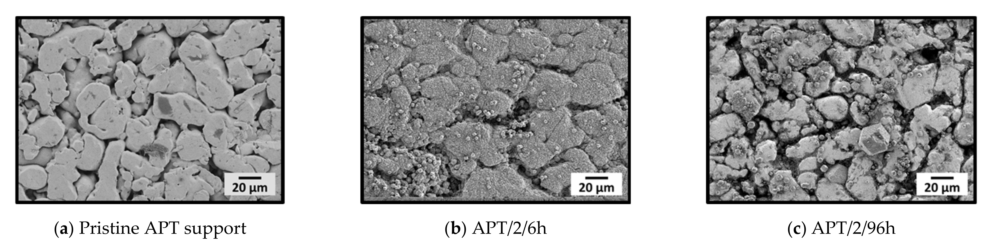
| APT/2/6h | 4.0 | 4.50 | 1.77 |
| APT/2/96h | 4.2 | 4.70 | 1.85 |
| Name | Support Specifications | Seeding | Synthesis | |||
|---|---|---|---|---|---|---|
| Material | Type a | - | Solvent | Support Position | Time/h | |
| Mott b/dr/l/6h | SS c | s | drop (dr) | DEF | lying | 6 |
| Mott b/dr/h/6h | SS c | s | drop (dr) | DEF | hanging | 6 |
| Mott b/db/h/6h | SS c | s | doctor blade (db) | DEF | hanging | 6 |
| Mott b/r/h/6h | SS c | s | rub (r) | DEF | hanging | 6 |
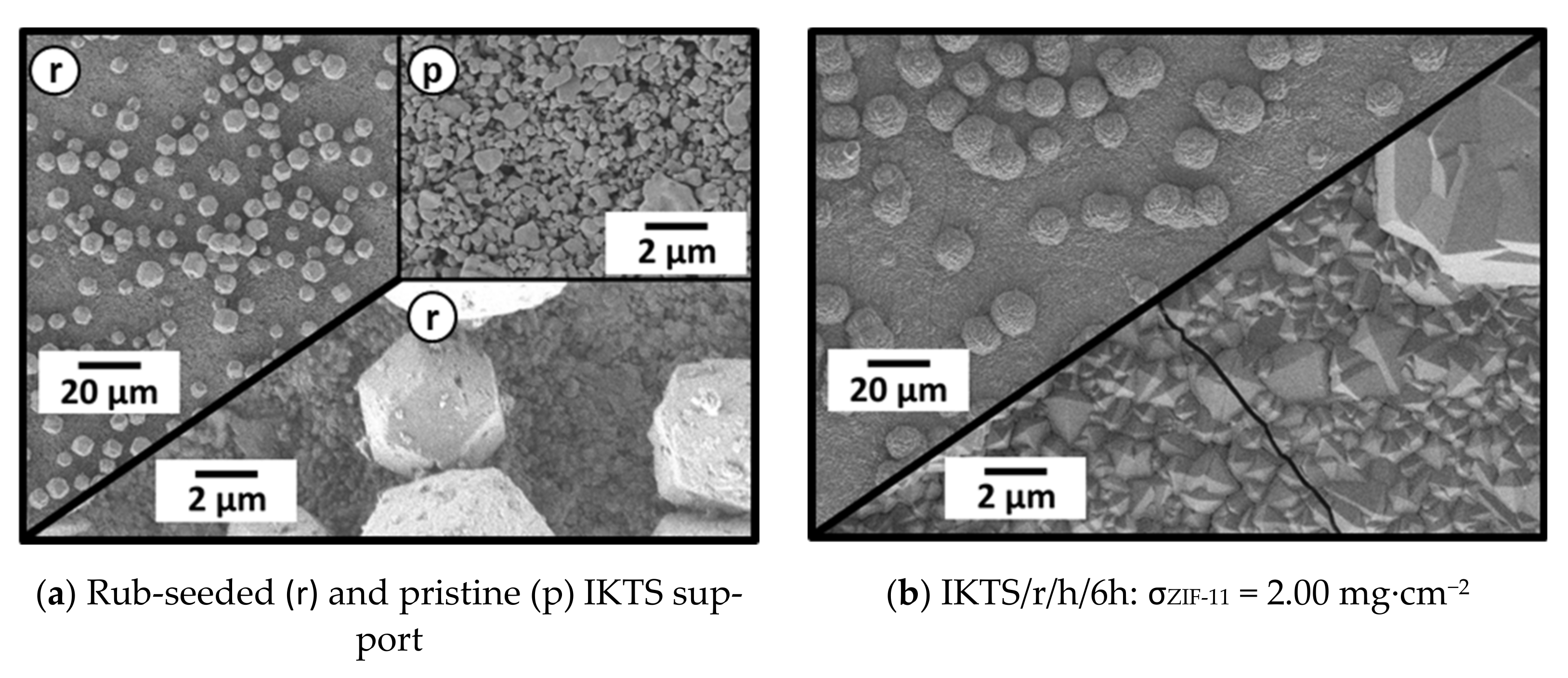
| IKTS d/r/h-6h | α-Al2O3 | as | rub (r) | DEF | hanging | 6 |
| Mott b/dr/hte/6h | SS c | s | drop (dr) | toluene/EtOH | hanging | 6 |
Publisher’s Note: MDPI stays neutral with regard to jurisdictional claims in published maps and institutional affiliations. |
© 2021 by the authors. Licensee MDPI, Basel, Switzerland. This article is an open access article distributed under the terms and conditions of the Creative Commons Attribution (CC BY) license (https://creativecommons.org/licenses/by/4.0/).
Share and Cite
Reif, B.; Somboonvong, J.; Hartmann, M.; Kaspereit, M.; Schwieger, W. Synthesis of ZIF-11 Membranes: The Influence of Preparation Technique and Support Type. Membranes 2021, 11, 523. https://doi.org/10.3390/membranes11070523
Reif B, Somboonvong J, Hartmann M, Kaspereit M, Schwieger W. Synthesis of ZIF-11 Membranes: The Influence of Preparation Technique and Support Type. Membranes. 2021; 11(7):523. https://doi.org/10.3390/membranes11070523
Chicago/Turabian StyleReif, Benjamin, Jan Somboonvong, Martin Hartmann, Malte Kaspereit, and Wilhelm Schwieger. 2021. "Synthesis of ZIF-11 Membranes: The Influence of Preparation Technique and Support Type" Membranes 11, no. 7: 523. https://doi.org/10.3390/membranes11070523