
Deep Penetration Microscopic Imaging with Non-Diffracting Airy Beams

 and
and 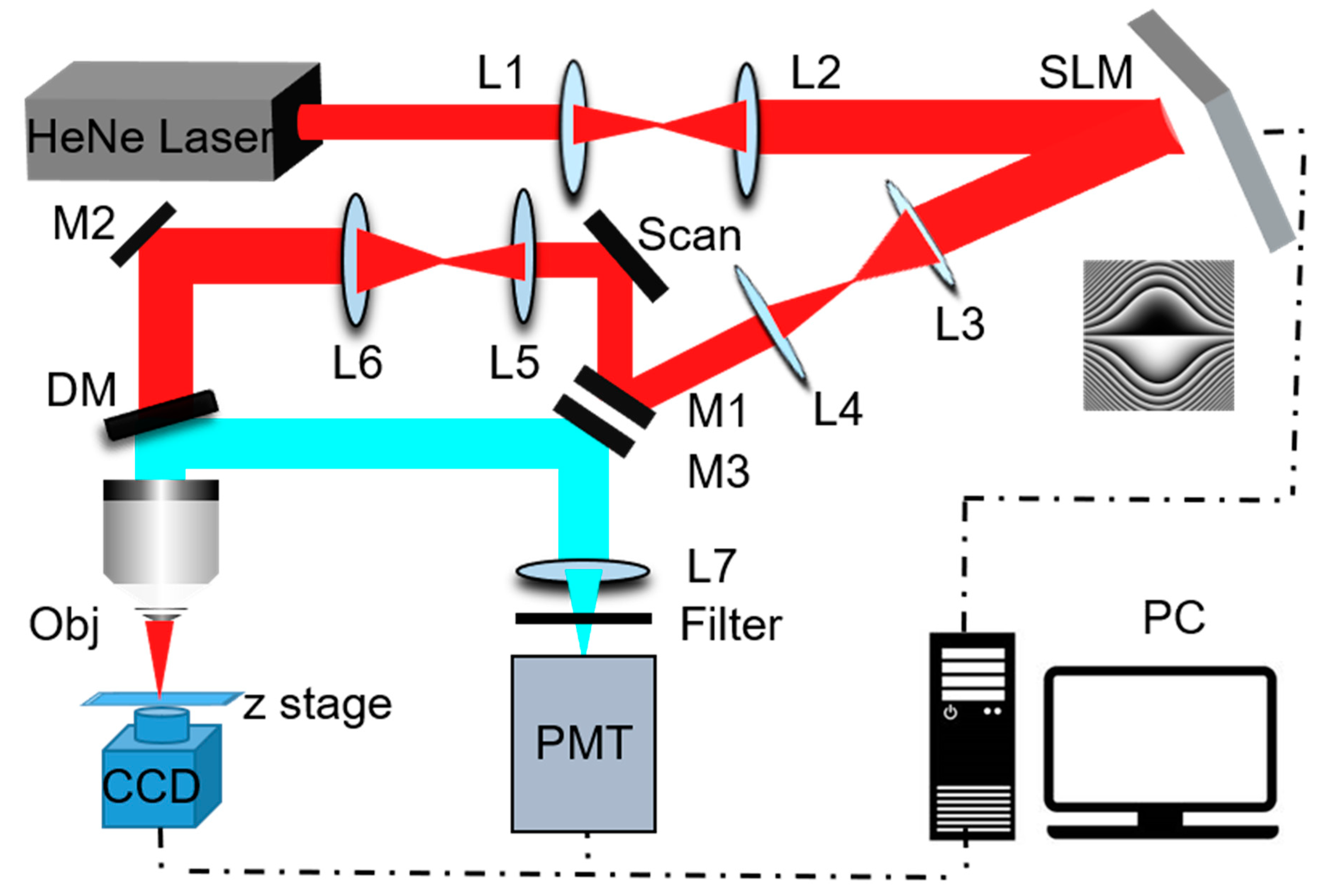
Abstract
:1. Introduction
2. System Set-Up
3. Results and Discussion
4. Conclusions
Supplementary Materials
Author Contributions
Funding
Institutional Review Board Statement
Data Availability Statement
Conflicts of Interest
References
- Tian, M.L.; Bao, Z.K.; Liu, Y. The laser confocal scanning microscopy and its applications. Opt. Instrum. 2001, 23, 16–19. [Google Scholar]
- Yang, W.; Chen, S.-L. Time-gated fluorescence imaging: Advances in technology and biological applications. J. Innov. Opt. Health Sci. 2020, 13. [Google Scholar] [CrossRef] [Green Version]
- Liu, X.; Lin, D.; Becker, W.; Niu, J.; Yu, B.; Liu, L.; Qu, J. Fast fluorescence lifetime imaging techniques: A review on challenge and development. J. Innov. Opt. Health Sci. 2019, 12, 783–790. [Google Scholar] [CrossRef] [Green Version]
- Tyson, R.K.; Wizinowich, P.L. Principles of Adaptive Optics. Phys. Today 1992, 45, 100. [Google Scholar] [CrossRef]
- Wang, L.; Yan, W.; Li, R.; Weng, X.; Zhang, J.; Yang, Z.; Liu, L.; Ye, T.; Qu, J. Aberration correction for improving the image quality in STED microscopy using the genetic algorithm. Nanophotonics 2018, 7, 1971–1980. [Google Scholar] [CrossRef] [PubMed]
- Zawadzki, R.J.; Jones, S.M.; Olivier, S.S.; Zhao, M.; Bower, B.A.; Izatt, J.A.; Choi, S.; Laut, S.; Werner, J.S. Adaptive-optics optical coherence tomography for high-resolution and high-speed 3D retinal in vivo imaging. Opt. Express 2005, 13, 8532–8546. [Google Scholar] [CrossRef] [Green Version]
- Yan, W.; Yang, Y.L.; Tan, Y.; Chen, X.; Li, Y.; Qu, J.L.; Ye, T. Coherent optical adaptive technique improves the spatial resolu-tion of STED microscopy in thick samples. Photonics Res. 2017, 5, 176–181. [Google Scholar] [CrossRef] [PubMed] [Green Version]
- Amaury, B.; Claude, B.A.; Geoffroy, L.; Mathias, F.; Alexandre, A. Multiple scattering limit in optical microscopy. Opt. Express 2017, 25, 28914. [Google Scholar]
- Vettenburg, T.; Dalgarno, H.I.C.; Nylk, J.; Coll-Lladó, C.; Ferrier, D.E.K.; Čižmár, T.; Gunn-Moore, F.J.; Dholakia, K. Light-sheet microscopy using an Airy beam. Nat. Methods 2014, 11, 541–544. [Google Scholar] [CrossRef] [Green Version]
- Ntziachristos, V. Going deeper than microscopy: the optical imaging frontier in biology. Nat. Methods 2010, 7, 603–614. [Google Scholar] [CrossRef]
- Niesner, R.A.; Hauser, A.E. Recent advances in dynamic intravital multi-photon microscopy. Cytom. Part A 2011, 79, 789–798. [Google Scholar] [CrossRef]
- Wang, F.; Wan, H.; Ma, Z.; Zhong, Y.; Sun, Q.; Tian, Y.; Qu, L.; Du, H.; Zhang, M.; Li, L.; et al. Light-sheet microscopy in the near-infrared II window. Nat. Methods 2019, 16, 545–552. [Google Scholar] [CrossRef] [PubMed]
- Keller, P.J.; Schmidt, A.D.; Santella, A.; Khairy, K.; Bao, Z.R.; Joachim, W.; Stelzer, E.H.K. Fast, high-contrast imaging of ani-mal development with scanned light sheet-based structured-illumination microscopy. Nat. Methods 2010, 7, 637. [Google Scholar] [CrossRef] [PubMed] [Green Version]
- Planchon, T.A.; Gao, L.; Milkie, D.E.; Davidson, M.W.; Galbraith, J.A.; Galbraith, C.G.; Betzig, E. Rapid three-dimensional isotropic imaging of living cells using Bessel beam plane illumination. Nat. Methods 2011, 8, 417–423. [Google Scholar] [CrossRef] [PubMed] [Green Version]
- Fahrbach, F.O.; Simon, P.; Rohrbach, A. Microscopy with self-reconstructing beams. Nat. Photonics 2010, 4, 780–785. [Google Scholar] [CrossRef]
- McGloin, D.; Dholakia, K. Bessel beams: Diffraction in a new light. Contemp. Phys. 2005, 46, 15–28. [Google Scholar] [CrossRef]
- IET Digital Library. Seshadri S. 2013. Available online: https://digital-library.theiet.org/content/books/10.1049/sbew518e_ch15 (accessed on 1 January 2013).
- Broky, J.; Siviloglou, G.A.; Dogariu, A.; Christodoulides, D.N. Self-healing properties of optical Airy beams. Opt. Express 2008, 16, 12880–12891. [Google Scholar] [CrossRef] [PubMed] [Green Version]
- Zhou, G.; Chu, X.; Chen, R.; Zhou, Y. Self-healing properties of cosh-Airy beams. Laser Phys. 2019, 29, 025001. [Google Scholar] [CrossRef]
- Tan, X.-J.; Kong, C.; Ren, Y.-X.; Lai, C.S.W.; Tsia, K.K.; Wong, K.K.Y. Volumetric two-photon microscopy with a non-diffracting Airy beam. Opt. Lett. 2019, 44, 391–394. [Google Scholar] [CrossRef]
- Nylk, J.; Yang, Z.; Preciado, M.; Mazilu, M.; Vettenburg, T.; Coll-Llado, C.; Ferrier, D.E.K.; Cizmar, T.; Gunn-Moore, F.J.; Dholakia, K. Airy Beams for Light-sheet Microscopy. Microsc. Microanal. 2015, 21, 1723–1724. [Google Scholar] [CrossRef] [Green Version]
- Jia, S.; Vaughan, J.C.; Zhuang, X. Isotropic 3D Super Resolution Imaging with Self-Bending Point Spread Function. Biophys. J. 2013, 104, 668. [Google Scholar] [CrossRef] [Green Version]
- Hutchins, R.; Zhang, M.; Ma, L.; Yu, P. Optical Scattering of Airy Beam and Gaussian Beam through Turbid Medium. In Proceedings of the Lasers and Electro-Optics 2015, San Jose, CA, USA, 10–15 May 2015. [Google Scholar] [CrossRef]
- Nagar, H.; Dekel, E.; Kasimov, D.; Roichman, Y. Non-diffracting beams for label-free imaging through turbid media. Opt. Lett. 2018, 43, 190–193. [Google Scholar] [CrossRef] [PubMed]


Publisher’s Note: MDPI stays neutral with regard to jurisdictional claims in published maps and institutional affiliations. |
© 2021 by the authors. Licensee MDPI, Basel, Switzerland. This article is an open access article distributed under the terms and conditions of the Creative Commons Attribution (CC BY) license (https://creativecommons.org/licenses/by/4.0/).
Share and Cite
Guo, Y.; Huang, Y.; Li, J.; Wang, L.; Yang, Z.; Liu, J.; Peng, X.; Yan, W.; Qu, J. Deep Penetration Microscopic Imaging with Non-Diffracting Airy Beams. Membranes 2021, 11, 391. https://doi.org/10.3390/membranes11060391
Guo Y, Huang Y, Li J, Wang L, Yang Z, Liu J, Peng X, Yan W, Qu J. Deep Penetration Microscopic Imaging with Non-Diffracting Airy Beams. Membranes. 2021; 11(6):391. https://doi.org/10.3390/membranes11060391
Chicago/Turabian StyleGuo, Yong, Yangrui Huang, Jin Li, Luwei Wang, Zhigang Yang, Jinyuan Liu, Xiao Peng, Wei Yan, and Junle Qu. 2021. "Deep Penetration Microscopic Imaging with Non-Diffracting Airy Beams" Membranes 11, no. 6: 391. https://doi.org/10.3390/membranes11060391