
Recent Impact of Microfluidics on Skin Models for Perspiration Simulation


Abstract
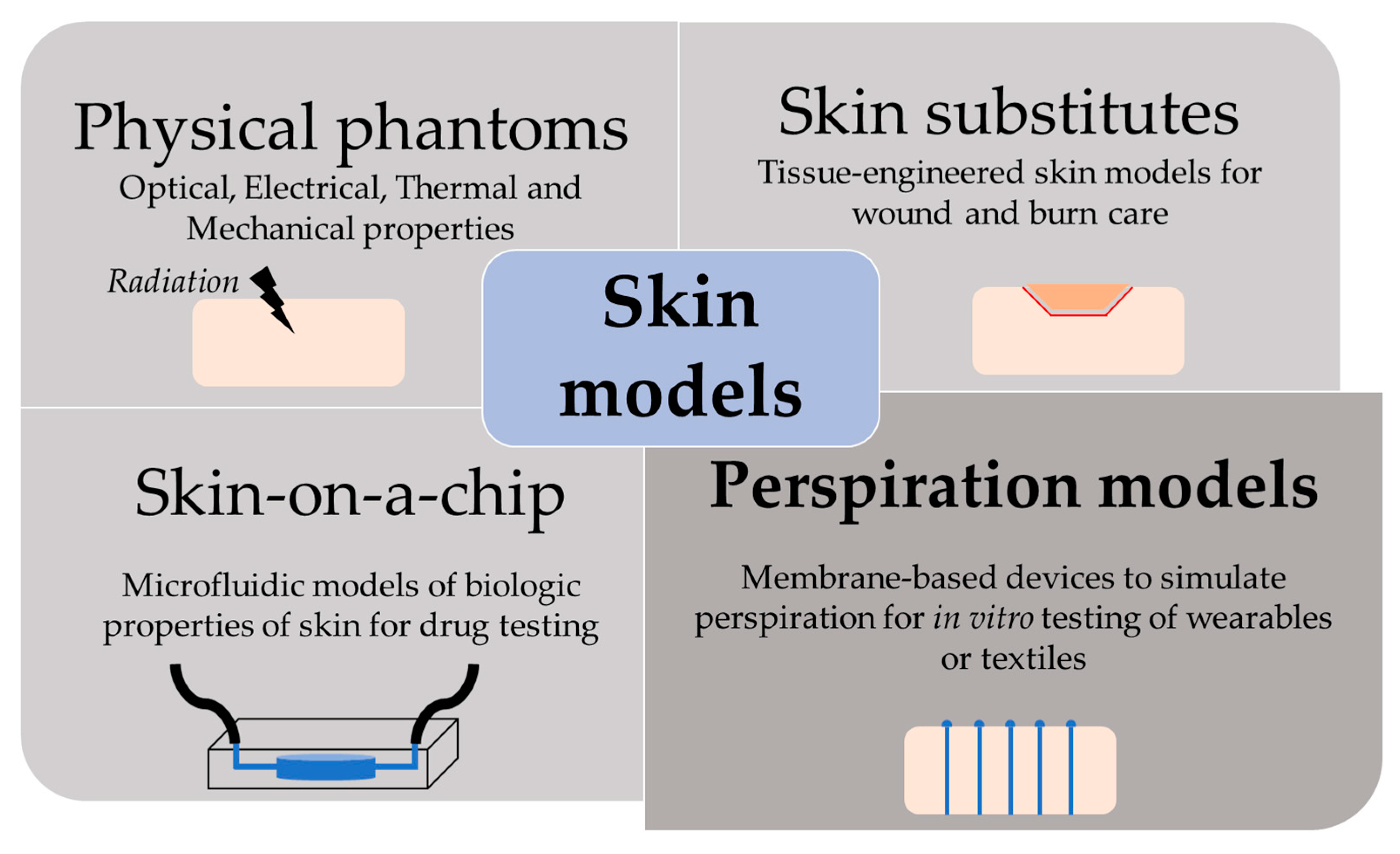
:1. Introduction
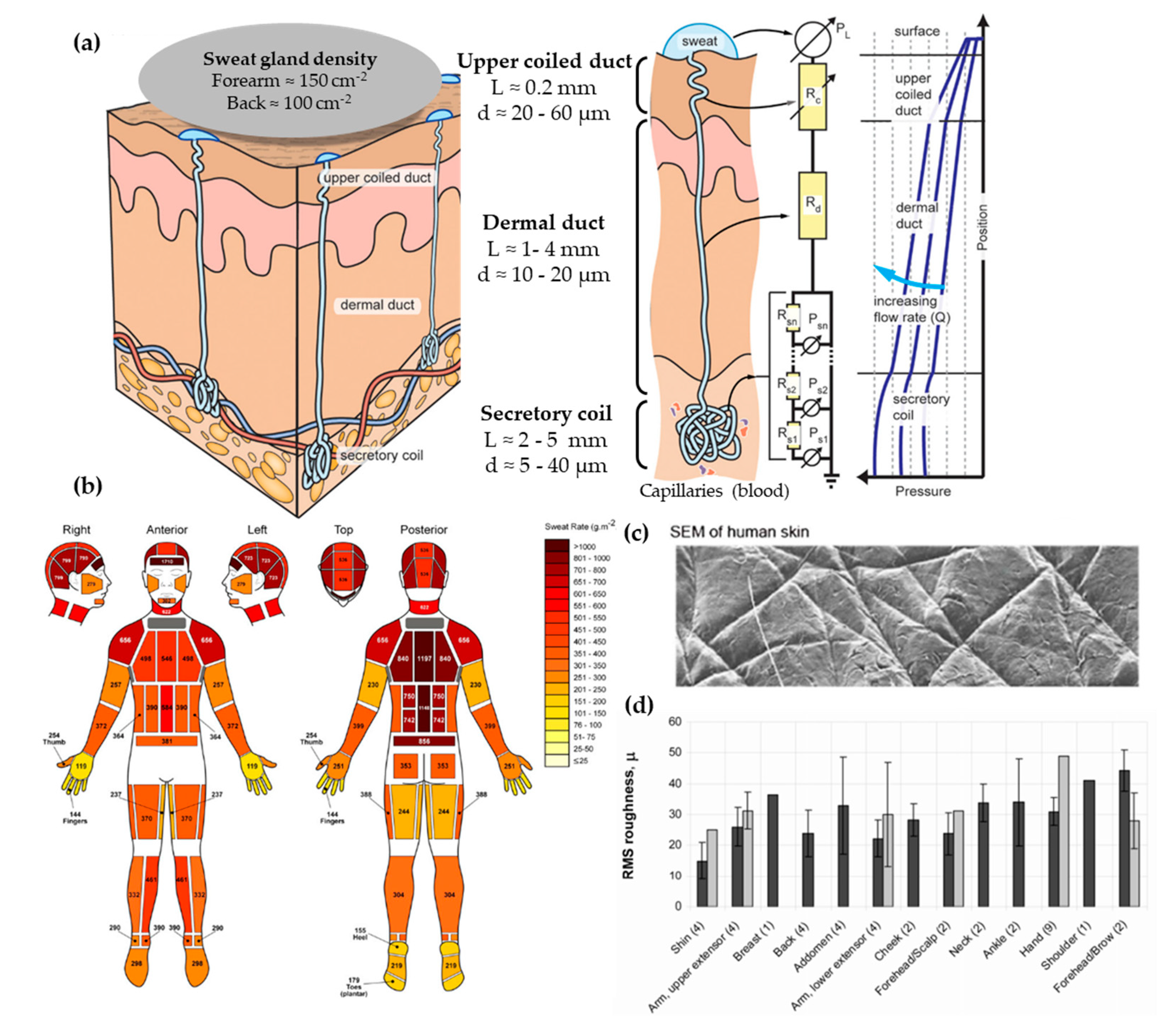
2. Skin and Perspiration Properties
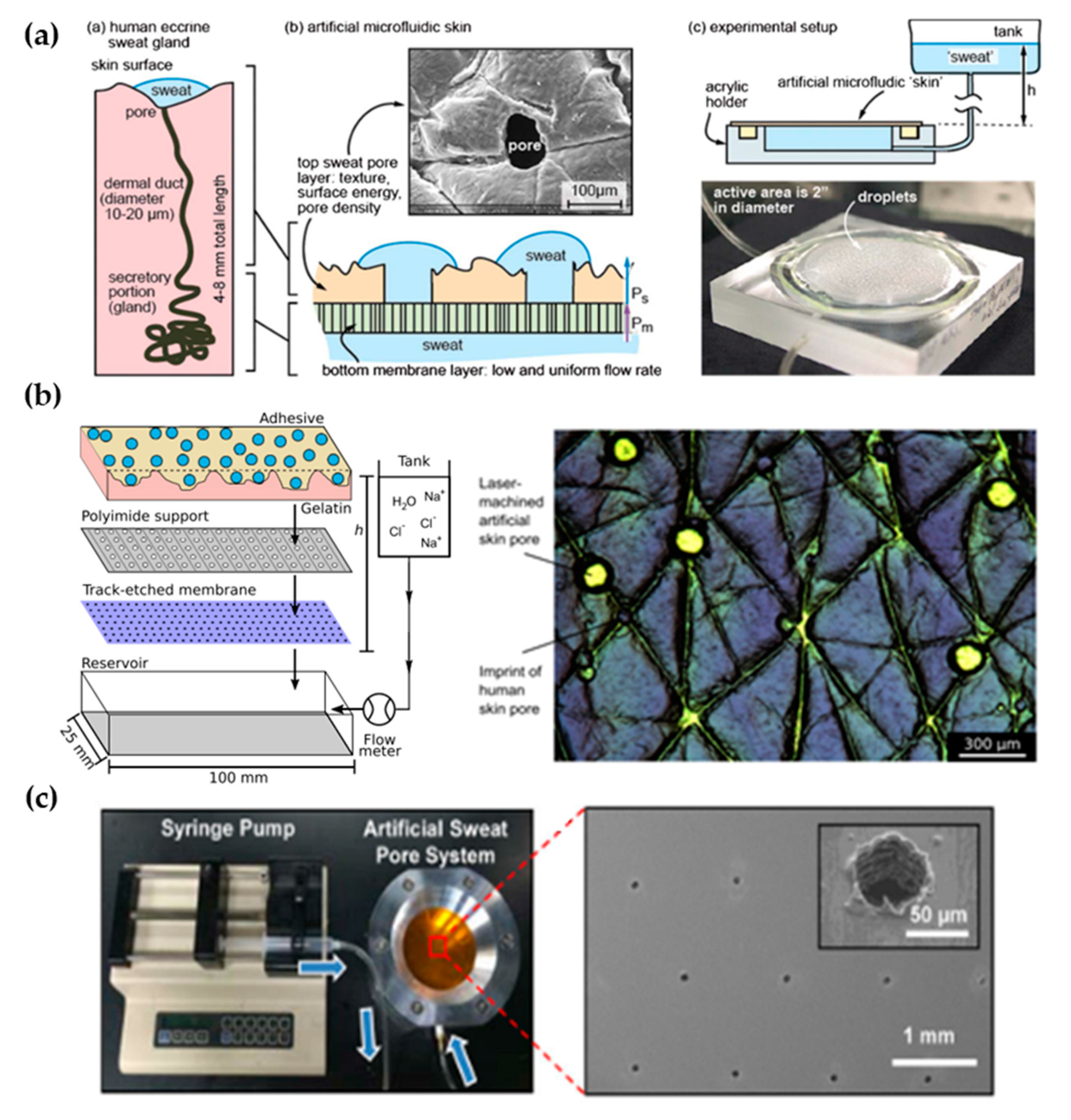
3. Perspiration Models
3.1. Laser-Machined Membranes
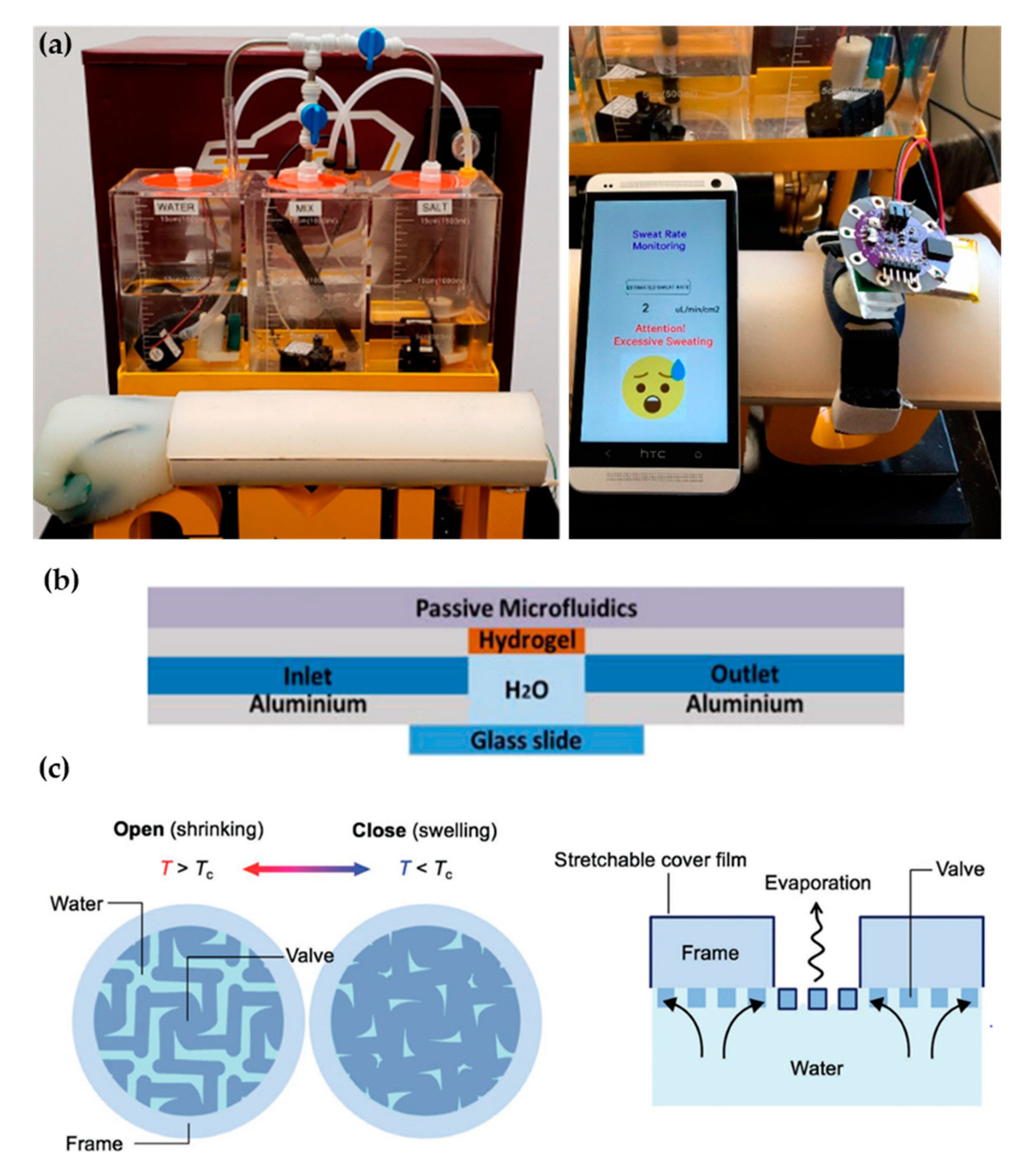
3.2. Alternative Approaches
4. Perspectives for Microfluidic Wearable Technology
5. Concluding Remarks
Author Contributions
Funding
Conflicts of Interest
References
- Frosch, P.J.; Kligman, A.M. Noninvasive Methods for the Quantification of Skin Functions: An Update on Methodology and Clinical Applications; Springer: Berlin, Germany, 2012. [Google Scholar]
- Dąbrowska, A.K.; Rotaru, G.-M.; Derler, S.; Spano, F.; Camenzind, M.; Annaheim, S.; Stämpfli, R.; Schmid, M.; Rossi, R.M. Materials used to simulate physical properties of human skin. Ski. Res. Technol. 2015, 22, 3–14. [Google Scholar] [CrossRef] [PubMed]
- Paul, M.; Mota, A.F.; Antink, C.H.; Blazek, V.; Leonhardt, S. Modeling photoplethysmographic signals in camera-based perfusion measurements: Optoelectronic skin phantom. Biomed. Opt. Express 2019, 10, 4353–4368. [Google Scholar] [CrossRef] [PubMed]
- Hull, E.L.; Nichols, M.G.; Foster, T.H. Quantitative broadband near-infrared spectroscopy of tissue-simulating phantoms containing erythrocytes. Phys. Med. Biol. 1998, 43, 3381–3404. [Google Scholar] [CrossRef]
- Hall, T.J.; Bilgen, M.; Insana, M.F.; Krouskop, T.A. Phantom materials for elastography. IEEE Trans. Ultrason. Ferroelectr. Freq. Control. 1997, 44, 1355–1365. [Google Scholar] [CrossRef]
- Cho, J.; Byun, H.; Lee, S.; Kim, J.K. Temperature distribution in deep tissue phantom during laser irradiation at 1,064 nm measured by thermocouples and thermal imaging technique. J. Vis. 2011, 14, 265–272. [Google Scholar] [CrossRef]
- Pinto, A.M.R.; Bertemes-Filho, P.; Paterno, A.S. Gelatin: A skin phantom for bioimpedance spectroscopy. Biomed. Phys. Eng. Exp. 2015, 1, 035001. [Google Scholar] [CrossRef]
- Lacik, J.; Hebelka, V.; Velim, J.; Raida, Z.; Puskely, J. Wideband Skin-Equivalent Phantom for V and W Band. IEEE Antennas Wirel. Propag. Lett. 2015, 15, 211–213. [Google Scholar] [CrossRef]
- Jachowicz, J.; McMullen, R.; Prettypaul, D. Indentometric analysis of in vivo skin and comparison with artificial skin models. Ski. Res. Technol. 2007, 13, 299–309. [Google Scholar] [CrossRef]
- Ramirez-San-Juan, J.C.; Aguilar, G.; Tuqan, A.T.; Kelly, K.M.; Nelson, J.S. Skin model surface temperatures during single and multiple cryogen spurts used in laser dermatologic surgery. Lasers Surg. Med. 2005, 36, 141–146. [Google Scholar] [CrossRef] [Green Version]
- Tuchin, V.V.; Bashkatov, A.N.; Genina, E.A.; Kochubey, V.I.; Lychagov, V.V.; Portnov, S.A.; Trunina, N.A.; Miller, D.R.; Cho, S.; Oh, H.; et al. Finger tissue model and blood perfused skin tissue phantom. In Proceedings of the Dynamics and Fluctuations in Biomedical Photonics VIII, San Francisco, CA, USA, 22–27 January 2011; Volme 7898, p. 78980Z. [Google Scholar]
- Shevchenko, R.V.; James, S.E. A review of tissue-engineered skin bioconstructs available for skin reconstruction. J. R. Soc. Interface 2009, 7, 229–258. [Google Scholar] [CrossRef] [Green Version]
- Mogoşanu, G.D.; Grumezescu, A.M. Natural and synthetic polymers for wounds and burns dressing. Int. J. Pharm. 2014, 463, 127–136. [Google Scholar] [CrossRef]
- Zhang, Q.; Sito, L.; Mao, M.; He, J.; Zhang, Y.S.; Zhao, X. Current advances in skin-on-a-chip models for drug testing. Microphysiological Syst. 2018, 2, 1–9. [Google Scholar] [CrossRef]
- Sutterby, E.; Thurgood, P.; Baratchi, S.; Khoshmanesh, K.; Pirogova, E. Microfluidic Skin-on-a-Chip Models: Toward Biomimetic Artificial Skin. Small 2020, 16, e2002515. [Google Scholar] [CrossRef] [PubMed]
- Baker, L.B. Physiology of sweat gland function: The roles of sweating and sweat composition in human health. Temperature 2019, 6, 211–259. [Google Scholar] [CrossRef] [PubMed] [Green Version]
- ISO. ISO EN. 11092: 2014 Textiles Physiological Effects. Measurement of Thermal and Water-Vapour Resistance under Steady-State Conditions (Sweating Guarded-Hotplate Test); ISO: Geneva, Switzerland, 2014. [Google Scholar]
- Lei, Z. Review of application of thermal manikin in evaluation on thermal and moisture comfort of clothing. J. Eng. Fibers Fabr. 2019, 14, 1558925019841548. [Google Scholar] [CrossRef]
- Fonseca, G. Sectional Dry-Heat-Transfer Properties of Clothing in Wind. Text. Res. J. 1975, 45, 30–34. [Google Scholar] [CrossRef]
- Fan, J. Simulation of perspiration in sweating fabric manikin-Walter. In Management of Natural Resources, Sustainable Development and Ecological Hazards; The Hong Kong Polytechnic University: Hong Kong, China, 2006; Volume 87, pp. 221–230. [Google Scholar] [CrossRef] [Green Version]
- Burke, R.; Curran, A.; Hepokoski, M. Integrating an active physiological and comfort model to the Newton sweating thermal manikin. In Proceedings of the 13th International Conference on Environmental Ergonomics (ICEE), Boston, MA, USA, 2–7 August 2009; pp. 313–317. [Google Scholar]
- Li, J.; Barker, R.L.; Deaton, A.S. Evaluating the Effects of Material Component and Design Feature on Heat Transfer in Firefighter Turnout Clothing by a Sweating Manikin. Text. Res. J. 2007, 77, 59–66. [Google Scholar] [CrossRef]
- Hussain, J.N.; Mantri, N.; Cohen, M.M. Working Up a Good Sweat—The Challenges of Standardising Sweat Collection for Metabolomics Analysis. Clin. Biochem. Rev. 2017, 38, 13–34. [Google Scholar]
- LeGrys, V.A.; Yankaskas, J.R.; Quittell, L.M.; Marshall, B.C.; Mogayzel, P.J. Diagnostic Sweat Testing: The Cystic Fibrosis Foundation Guidelines. J. Pediatr. 2007, 151, 85–89. [Google Scholar] [CrossRef]
- Brasier, N.; Eckstein, J. Sweat as a Source of Next-Generation Digital Biomarkers. Digit. Biomarkers 2019, 3, 155–165. [Google Scholar] [CrossRef]
- De Giovanni, N.; Fucci, N. The Current Status of Sweat Testing For Drugs of Abuse: A Review. Curr. Med. Chem. 2013, 20, 545–561. [Google Scholar] [CrossRef]
- Brothers, M.C.; Debrosse, M.; Grigsby, C.C.; Naik, R.R.; Hussain, S.M.; Heikenfeld, J.; Kim, S.S. Achievements and Challenges for Real-Time Sensing of Analytes in Sweat within Wearable Platforms. Accounts Chem. Res. 2019, 52, 297–306. [Google Scholar] [CrossRef]
- Ghaffari, R.; Choi, J.; Raj, M.S.; Chen, S.; Lee, S.P.; Reeder, J.T.; Aranyosi, A.J.; Leech, A.; Li, W.; Schon, S.; et al. Soft Wearable Systems for Colorimetric and Electrochemical Analysis of Biofluids. Adv. Funct. Mater. 2019, 30, 1–10. [Google Scholar] [CrossRef]
- Li, S.; Ma, Z.; Cao, Z.; Pan, L.; Shi, Y. Advanced Wearable Microfluidic Sensors for Healthcare Monitoring. Small 2020, 16, e1903822. [Google Scholar] [CrossRef]
- Taylor, N.A.; Machado-Moreira, C.A. Regional variations in transepidermal water loss, eccrine sweat gland density, sweat secretion rates and electrolyte composition in resting and exercising humans. Extreme Physiol. Med. 2013, 2, 1–30. [Google Scholar] [CrossRef] [Green Version]
- Wilke, K.; Martin, A.; Terstegen, L.; Biel, S.S. A short history of sweat gland biology. Int. J. Cosmet. Sci. 2007, 29, 169–179. [Google Scholar] [CrossRef] [PubMed]
- Sonner, Z.; Wilder, E.M.; Heikenfeld, J.; Kasting, G.B.; Beyette, F.R.; Swaile, D.; Sherman, F.F.; Joyce, J.L.; Hagen, J.A.; Kelleyloughnane, N.; et al. The microfluidics of the eccrine sweat gland, including biomarker partitioning, transport, and biosensing implications. Biomicrofluidics 2015, 9, 031301. [Google Scholar] [CrossRef] [Green Version]
- Smith, C.J.; Havenith, G. Body mapping of sweating patterns in male athletes in mild exercise-induced hyperthermia. Graefe’s Arch. Clin. Exp. Ophthalmol. 2011, 111, 1391–1404. [Google Scholar] [CrossRef] [Green Version]
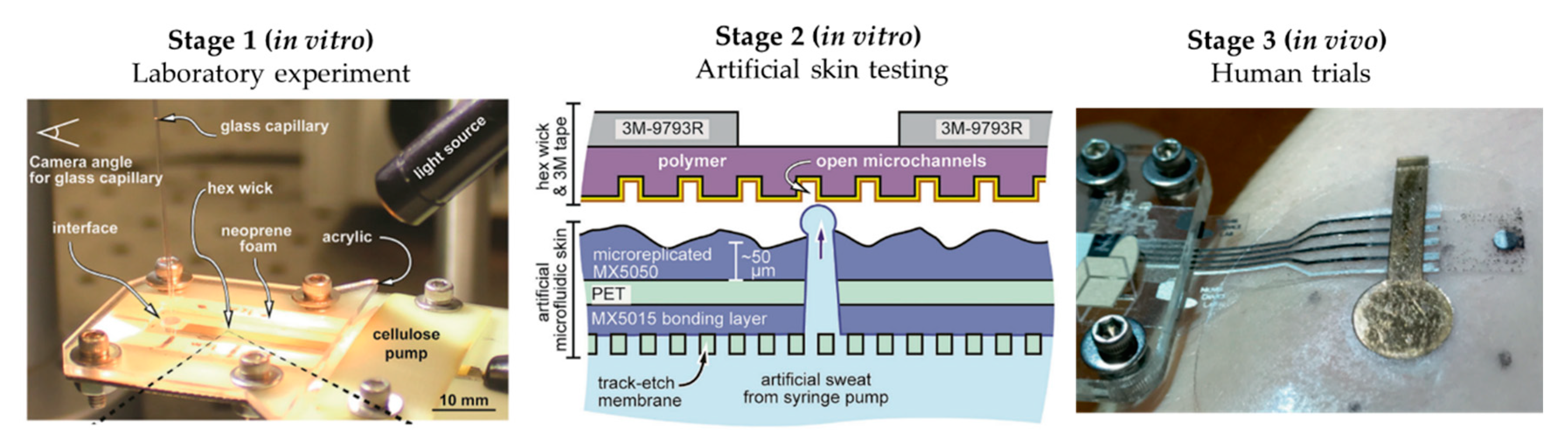
- Hou, L.; Hagen, J.; Wang, X.; Papautsky, I.; Naik, R.; Kelley-Loughnane, N.; Heikenfeld, J. Artificial microfluidic skin for in vitro perspiration simulation and testing. Lab Chip 2013, 13, 1868–1875. [Google Scholar] [CrossRef]
- Qu, M.; Hamdani, S.; Bunce, J.A. The physiology and genetics of stomatal adjustment under fluctuating and stressed environments. In Applied Photosynthesis: New Progress; Intech: London, UK, 2016. [Google Scholar] [CrossRef] [Green Version]
- Simmers, P.; Li, S.K.; Kasting, G.; Heikenfeld, J. Prolonged and localized sweat stimulation by iontophoretic delivery of the slowly-metabolized cholinergic agent carbachol. J. Dermatol. Sci. 2018, 89, 40–51. [Google Scholar] [CrossRef] [Green Version]
- Schulz, I.J. Micropuncture studies of the sweat formation in cystic fibrosis patients. J. Clin. Investig. 1969, 48, 1470–1477. [Google Scholar] [CrossRef]
- Garcia-Cordero, E.; Bellando, F.; Zhang, J.; Wildhaber, F.; Longo, J.; Guérin, H.; Ionescu, A.M. Three-Dimensional Integrated Ultra-Low-Volume Passive Microfluidics with Ion-Sensitive Field-Effect Transistors for Multiparameter Wearable Sweat Analyzers. ACS Nano 2018, 12, 12646–12656. [Google Scholar] [CrossRef]
- Henkin, S.D.; Sehl, P.L.; Meyer, F. Sweat Rate and Electrolyte Concentration in Swimmers, Runners, and Nonathletes. Int. J. Sports Physiol. Perform. 2010, 5, 359–366. [Google Scholar] [CrossRef] [Green Version]
- Ginn, M.; Noyes, C.; Jungermann, E. The contact angle of water on viable human skin. J. Colloid Interface Sci. 1968, 26, 146–151. [Google Scholar] [CrossRef]
- Kovalev, A.E.; Dening, K.; Persson, B.N.J.; Gorb, S.N. Surface topography and contact mechanics of dry and wet human skin. Beilstein J. Nanotechnol. 2014, 5, 1341–1348. [Google Scholar] [CrossRef] [Green Version]
- Hashimoto, K. New Methods for Surface Ultrastructure: Comparative Studies of Scanning Electron Microscopy, Transmission Electron Microscopy and Replica Method. Int. J. Dermatol. 1974, 13, 357–381. [Google Scholar] [CrossRef]
- Snakenborg, D.; Klank, H.; Kutter, J.P. Microstructure fabrication with a CO2 laser system. J. Micromech. Microengin. 2003, 14, 182–189. [Google Scholar] [CrossRef]
- Matellan, C.; Hernández, A.E.D.R. Cost-effective rapid prototyping and assembly of poly(methyl methacrylate) microfluidic devices. Sci. Rep. 2018, 8, 1–13. [Google Scholar] [CrossRef] [PubMed] [Green Version]
- Eiler, J.; Hansen, D.; Bingöl, B.; Hansen, K.; Heikenfeld, J.; Thormann, E. In vitro evaluation of skin adhesives during perspiration. Int. J. Adhes. Adhes. 2020, 99, 102574. [Google Scholar] [CrossRef]
- Hansen, D.; Moghaddam, S.Z.; Eiler, J.; Hansen, K.; Thormann, E. Performance of Polymeric Skin Adhesives during Perspiration. ACS Appl. Polym. Mater. 2020, 2, 1535–1542. [Google Scholar] [CrossRef]
- Koh, A.; Kang, D.; Xue, Y.; Lee, S.; Pielak, R.M.; Kim, J.; Hwang, T.; Min, S.; Banks, A.; Bastien, P.; et al. A soft, wearable microfluidic device for the capture, storage, and colorimetric sensing of sweat. Sci. Transl. Med. 2016, 8, 366ra165. [Google Scholar] [CrossRef] [Green Version]
- Liu, C.; Huang, Y.; Li, S.; Chen, Y.; Wang, W.Z.; Yu, J.; Shih, W. Microelectromechanical system-based biocompatible artificial skin phantoms. Micro Nano Lett. 2019, 14, 333–338. [Google Scholar] [CrossRef]
- Brueck, A.; Bates, K.; Wood, T.; House, W.; Martinez, Z.; Peters, S.; Root, B.; Yelamarthi, K.; Kaya, T. An Artificial Sweating System for Sweat Sensor Testing Applications. Electronics 2019, 8, 606. [Google Scholar] [CrossRef] [Green Version]
- Turcin, I.; Cosma, C.; Abdallah, A.; Balc, N. Design for Additive Manufacturing a Sweat Gland Simulator. In Proceedings of the 7th International Conference on Additive Technologies, Maribor, Slovenia, 10–11 October 2018. [Google Scholar]
- Gong, H.; Bickham, B.P.; Woolley, A.T.; Nordin, G.P. Custom 3D printer and resin for 18 μm × 20 μm microfluidic flow channels. Lab Chip 2017, 17, 2899–2909. [Google Scholar] [CrossRef]
- Garcia-Cordero, E.; Wildhaber, F.; Bellando, F.; Longo, J.; Fernandez-Bolanos, M.; Guerin, H.; Ionescu, A.M. Embedded passive nano-liter micropump for sweat collection and analysis. In Proceedings of the 2018 IEEE Micro Electro Mechanical Systems (MEMS), Belfast, Northern Ireland, 21–25 January 2018; pp. 1217–1220. [Google Scholar] [CrossRef]
- Kim, J.; Im, S.; Kim, J.H.; Kim, S.M.; Lee, S.M.; Lee, J.; Im, J.P.; Woo, J.; Moon, S.E. Artificial Perspiration Membrane by Programmed Deformation of Thermoresponsive Hydrogels. Adv. Mater. 2020, 32, 1–7. [Google Scholar] [CrossRef]
- Twine, N.B.; Norton, R.M.; Brothers, M.; Hauke, A.; Gomez, E.F.; Heikenfeld, J. Open nanofluidic films with rapid transport and no analyte exchange for ultra-low sample volumes. Lab Chip 2018, 18, 2816–2825. [Google Scholar] [CrossRef]
- Brueck, A.; Iftekhar, T.; Stannard, A.B.; Yelamarthi, K.; Kaya, T. A Real-Time Wireless Sweat Rate Measurement System for Physical Activity Monitoring. Sensors 2018, 18, 533. [Google Scholar] [CrossRef] [PubMed] [Green Version]
- Choi, J.; Bandodkar, A.J.; Reeder, J.T.; Ray, T.R.; Turnquist, A.; Kim, S.B.; Nyberg, N.; Hourlier-Fargette, A.; Model, J.B.; Aranyosi, A.J.; et al. Soft, Skin-Integrated Multifunctional Microfluidic Systems for Accurate Colorimetric Analysis of Sweat Biomarkers and Temperature. ACS Sens. 2019, 4, 379–388. [Google Scholar] [CrossRef]
- Reeder, J.T.; Xue, Y.; Franklin, D.; Deng, Y.; Choi, J.; Prado, O.; Kim, R.; Liu, C.; Hanson, J.; Ciraldo, J.; et al. Resettable skin interfaced microfluidic sweat collection devices with chemesthetic hydration feedback. Nat. Commun. 2019, 10, 1–12. [Google Scholar] [CrossRef] [Green Version]


| Work | Sweat Gland Diameter (µm) | Sweat Gland Length (mm) | Sweat Gland Density (cm−2) | Contact Angle (°) | Roughness Ra (µm) | Sweat Rate (µL/min·cm2) | Fabrication Method | Flow Control |
|---|---|---|---|---|---|---|---|---|
| Human skin [32] | 10–20 | 1–4 | 100–550 | 80–110 [41] | 10–50 (RMS) [35] | 0.2–4 | - | - |
| Hou et al. [34] | 80 | <0.1 | 200 | θa= 76 | - | 0.8–5 | CO2 laser | Hydrostatic pressure |
| Eiler et al. [45] | 86.8 ± 17.5 | <0.1 | 100 | 69.2 ± 3.6 | 12.1 ± 1.3 | 0.5–2 | CO2 laser | Syringe pump |
| Hansen et al. [46] | 250 | <0.1 | 100 | 77.5 ± 0.8 | 8.4 ± 4.5 | 0.5–2 | CO2 laser | Hydrostatic pressure |
| Koh et al. [47] | 60 | <0.1 | 100 | - | - | 1.3 | CO2 laser | Syringe pump |
| Liu et al. [48] | 20 ± 3 | <0.1 | 620 | - | - | - | Lift-off + CO2 laser | - |
Publisher’s Note: MDPI stays neutral with regard to jurisdictional claims in published maps and institutional affiliations. |
© 2021 by the authors. Licensee MDPI, Basel, Switzerland. This article is an open access article distributed under the terms and conditions of the Creative Commons Attribution (CC BY) license (http://creativecommons.org/licenses/by/4.0/).
Share and Cite
Rabost-Garcia, G.; Farré-Lladós, J.; Casals-Terré, J. Recent Impact of Microfluidics on Skin Models for Perspiration Simulation. Membranes 2021, 11, 150. https://doi.org/10.3390/membranes11020150
Rabost-Garcia G, Farré-Lladós J, Casals-Terré J. Recent Impact of Microfluidics on Skin Models for Perspiration Simulation. Membranes. 2021; 11(2):150. https://doi.org/10.3390/membranes11020150
Chicago/Turabian StyleRabost-Garcia, Genís, Josep Farré-Lladós, and Jasmina Casals-Terré. 2021. "Recent Impact of Microfluidics on Skin Models for Perspiration Simulation" Membranes 11, no. 2: 150. https://doi.org/10.3390/membranes11020150