Article

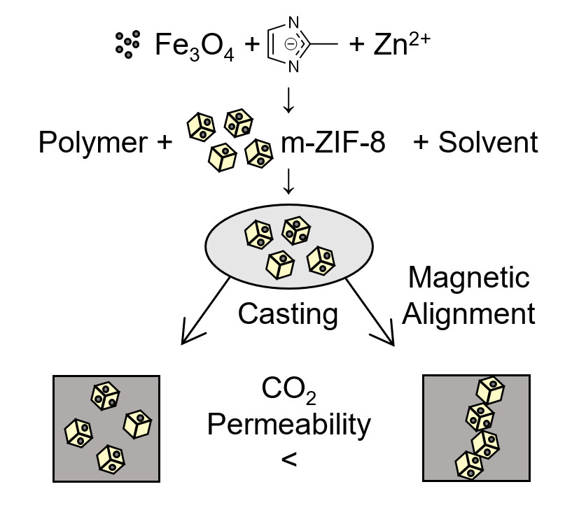
Magnetically Aligned and Enriched Pathways of Zeolitic Imidazolate Framework 8 in Matrimid Mixed Matrix Membranes for Enhanced CO2 Permeability

Membrane Materials and Processes, Department of Chemical Engineering and Chemistry, Eindhoven University of Technology, P.O. Box 513, 5600 MB Eindhoven, The Netherlands
*
Author to whom correspondence should be addressed.
Membranes 2020, 10(7), 155; https://doi.org/10.3390/membranes10070155
Submission received: 24 June 2020 / Revised: 14 July 2020 / Accepted: 15 July 2020 / Published: 17 July 2020
(This article belongs to the Special Issue Mixed Matrix Membranes II. From Lab Scale towards Application)

Abstract

:
Metal-organic frameworks (MOFs) as additives in mixed matrix membranes (MMMs) for gas separation have gained significant attention over the past decades. Many design parameters have been investigated for MOF based MMMs, but the spatial distribution of the MOF throughout MMMs lacks investigation. Therefore, magnetically aligned and enriched pathways of zeolitic imidazolate framework 8 (ZIF−8) in Matrimid MMMs were synthesized and investigated by means of their N2 and CO2 permeability. Magnetic ZIF−8 (m–ZIF−8) was synthesized by incorporating Fe3O4 in the ZIF−8 structure. The presence of Fe3O4 in m–ZIF−8 showed a decrease in surface area and N2 and CO2 uptake, with respect to pure ZIF−8. Alignment of m–ZIF−8 in Matrimid showed the presence of enriched pathways of m–ZIF−8 through the MMMs. At 10 wt.% m–ZIF−8 incorporation, no effect of alignment was observed for the N2 and CO2 permeability, which was ascribed anon-ideal tortuous alignment. However, alignment of 20 wt.% m–ZIF−8 in Matrimid showed to increase the CO2 diffusivity and permeability (19%) at 7 bar, while no loss in ideal selectivity was observed, with respect to homogeneously dispersed m–ZIF−8 membranes. Thus, the alignment of MOF particles throughout the matrix was shown to enhance the CO2 permeability at a certain weight content of MOF.

Graphical Abstract

1. Introduction

Polymeric membranes for gas separation are used for purification, generation and separation of gaseous streams, besides other methods, such as (cryogenic) distillation, pressure swing adsorption and amine scrubbing [1]. In comparison with these other technologies, gas separation membranes may simplify the operational process, provide a relatively easy possibility for upscaling and require no phase change [1]. Despite these advantages, polymeric membranes exhibit a negative correlation between selectivity and permeability, which is known as Robeson’s upper bound [2,3]. The incorporation of additives in polymeric membranes, i.e., a mixed matrix membrane (MMM), can result in shifting the membrane performance towards this upper bound or even surpassing it [4,5,6,7]. Additives that are used to enhance the MMM separation performance and have gained significant attention over the past decades are metal-organic frameworks (MOFs) [8]. MOFs are microporous crystalline networks where metal ions, i.e., the nodes, are coordinated by organic linkers. Like other microporous materials, such as zeolites, MOFs have large surface areas. The chemical affinity, surface area and pore size of MOFs are highly tunable by varying the linker between the metal nodes. These exceptional properties make MOFs promising candidates for the application in the field of gas separation and storage [9].
Zeolitic imidazolate frameworks (ZIFs) are a subclass of MOFs with a crystal structure that exists out of zinc or cobalt cations and imidalozate linkers [10]. ZIFs owe their name to the metal-imidazolate-metal bond angle, which is the same as the Si-O-Si bond angle in zeolites. As the chemical and thermal stability can be an issue in the application of MOFs, ZIFs are a promising subclass of MOFs due to their outstanding chemical and thermal stability [11,12]. One particular type of ZIF that has gained significant attention in the field of gas separation MMMs is ZIF−8, which exists out of zinc ions and 2-methylimidazolate (mIm) linkers [10]. Due to the pore dimensions (pore aperture = 3.4 Å, pore diameter = 11.6 Å), ZIF−8 exhibits high gas uptake and sieving properties towards gases with a small kinetic diameter, e.g., CO2 and H2 [10,13]. The size and shape of ZIF−8, which has an isotropic sodalite topology, can be tuned by a variety of parameters, such as solvent type, zinc salt type, precursor ratio, concentrations of the precursor and synthesis method [10,14,15,16,17,18]. Besides the size and shape of ZIF−8, catalytic and magnetic properties can be introduced to the MOF by adding nanoparticles to the synthesis mixture, which extends the field of application of ZIF−8 [17,19,20,21]. Pure ZIF−8 membranes on porous supports and ZIF−8 based MMMs have demonstrated the potential of ZIF−8 for gas separation applications, by means of relatively high selectivity and permeability [8,13,22,23,24]. Even membranes of single crystal ZIF−8 structures have been reported [25]. Generally, the addition of ZIF−8 in a polymer matrix, to form MMMs, results in an increased gas permeability. Moreover, depending on the gas pair and MOF load, the selectivity can improve as well [8].
MMMs consisting of a polymeric matrix with MOF additives provide a wide field of research, where the MMM can be optimized in various manners, since there are many parameters to tune. Firstly, by introducing CO2-philic linkers in MOFs, the separation of CO2/CH4 by MMMs can be significantly improved [5]. Interfacial compatibility between the matrix and the MOF can be optimized by matrix modification or the addition of a dispersant, where the improved MOF embedding results in increased CO2/CH4 selectivity [26,27]. The MOF size is an important factor as well for the MMM performance. For example, increasing the MOF size from 50 to 150 nm results in improved H2/CO2 selectivity and permeability. This observation is ascribed to the decreased particle agglomeration in the matrix due to the decreased external surface area of the MOF particles [28]. Lastly, annealing temperature of MMMs affects their performance as well. Both the mechanical properties (e.g., toughness, hardness, yield and fracture strength), as well as the permeability of MMMs, show optimal performance when annealed at elevated temperatures [29,30].
One type of optimization of MOF based MMMs that is only marginally explored in the field of gas separation membranes is the spatial distribution of MOFs in MMMs, i.e., aligning three-dimensional isotropic MOFs parallel to the direction of permeation through the membrane. This MOF alignment should form “molecular highways” through the membrane due to the highly permeable nature of MOFs, with respect to the polymer matrix. Alignment of one-dimensional and two-dimensional additives has been performed in MMMs. Techniques for achieving these aligned MMMs were based on external magnetic and electric fields or substrate directed, i.e., a template determines the orientation [31,32,33,34]. For both one-dimensional (i.e., carbon nanotubes) and two-dimensional (i.e., montmorillonite) additives, an improved gas separation performance was observed [32,33,34]. Both one and two-dimensional alignment depends on the orientation of the additive, e.g., carbon nanotubes (a one-dimensional additive), which are permeable through their interior, are oriented parallel to the permeation path. However, three-dimensional additives, e.g., ZIF−8, are permeable in the x, y and z direction, due to their isotropy. Therefore, alignment of three-dimensional additives does not rely on spatial orientation, but on spatial rearrangement.
Hypothetically, the permeability of MMMs with isotropic MOFs should be enhanced by alignment of the MOF, if the permeability of the MOF is significantly higher than the matrix. Alignment will form pathways of the three-dimensional MOF and as a consequence will the permeation behavior be shifted towards the MOF permeability. Thus, the distance between MOFs will be reduced due to the alignment. The permeation through the matrix, i.e., the rate determining component, is minimized through these permeation paths. This improved use of the MOFs could hypothetically reduce the amount of MOFs required in MMMs to obtain a desired permeability.
Therefore, this research aims to align a three-dimensional isotropic additive in an MMM in such a manner that the MOF will form local clusters which will lie parallel to the gas permeation path. Since it has been shown that magnetic properties can be introduced in ZIF−8 and that ZIF−8 as an additive in MMMs increases permeability, this MOF is selected as additive for the MMM. The polyimide Matrimid® 5218 is selected as polymer matrix. Nanoscale sized magnetite (Fe3O4), an iron oxide with a significant higher magnetic susceptibility than other iron oxides, will be used as ferrimagnetic material to magnetize ZIF−8. Additive alignment will be done in a magnetic field, since other magnetic isotropic particles have already been successfully aligned in the direction of the magnetic field lines by magnetic fields in composite materials [35,36]. Lastly, the MMMs will be evaluated for their single gas permeability of CO2 and N2. This gas pair is selected since it may resemble partially a flue gas composition [37]. Moreover, N2 behaves similar to CO by means of thermal diffusion [38]. Furthermore, the kinetic diameters and critical temperatures both gases are in the same range (dN2 = 3.64 Å, dCO = 3.76 Å, Tc,N2 = −147 °C, Tc,CO = −140 °C). Therefore, CO2/N2 gas mixtures resemble partially the output stream of CO2 plasma conversion into CO as well [39].

2. Materials and Methods

2.1. Chemicals

Magnetite (Fe3O4, daverage = 8 nm, 99.9% purity, US Research Nanomaterials, Houston, TX, USA), 2-methylimidazole (mIm, 99% purity, Sigma-Aldrich, Zwijndrecht, The Netherlands), poly(ethylene glycol) (PEG, 1 kDa, Sigma-Aldrich, Zwijndrecht, The Netherlands), N,N-dimethylformamide (DMF, ≥99.9% purity, Sigma-Aldrich, Zwijndrecht, The Netherlands), zinc nitrate hexahydrate (Zn(NO3)2 · 6 H2O, 98% purity, Thermofischer Acros Organic, Geel, Belgium), Matrimid® 5218 (Matrimid, kindly provided by Huntsman, Basel, Switzerland), ultrapure water (PURELAB Option demineralizer, Veolia Water Solutions and Technologies, Ede, The Netherlands), helium (5.0 grade, Linde gas, Schiedam, The Netherlands), nitrogen (4.5 grade, Linde gas, Schiedam, The Netherlands) and carbon dioxide (4.5 grade, Linde gas, Schiedam, The Netherlands) were used as received without further purification.

2.2. Magnetic ZIF−8 Synthesis

Magnetic ZIF−8 (m–ZIF−8) and ZIF−8 were prepared by an aqueous room temperature method. First, 10 mL ultrapure water was added to 20 mg Fe3O4. The suspension was sonicated with a Sonics Vibra-Cell ultrasonication probe (Sonics and Materials Inc., Newtown, Connecticut, USA) at 35% probe intensity for 10 min. Meanwhile, 500 mg PEG, which is used as surfactant, was dissolved in 10 mL ultrapure water. The sonicated Fe3O4 suspension and PEG solution were added together and the mixture was stabilized for 15 min. Again, the mixture was sonicated with a sonication probe for 10 min and stabilized for 15 min. The PEG stabilized Fe3O4 was washed three times with ultrapure water to remove the excess PEG by simply containing the Fe3O4 with a magnet. 10 mL of ultrapure water was added to the magnetic particles. 150 mg Zn(NO3)2 · 6 H2O (0.50 mmol) was added to the stabilized Fe3O4 suspension. A solution of 1.64 g mIm (20 mmol) in 15 mL ultrapure water was added to the mixture. The mixture was stirred for 30 min while ZIF−8 formation occurred. The product was washed three times by containing the product with a magnet. M-ZIF−8 was dried in a vacuum oven overnight at 75 °C and 350 mbar. Lastly, the product was further dried for 24 hr at 100 °C and 0 mbar. Traditional ZIF−8 was synthesized as a reference by the same method as the m–ZIF−8 synthesis, but without the presence of PEG stabilized Fe3O4. Since ZIF−8 is not magnetic by nature, washing was performed by centrifuging the ZIF−8 suspension with a CompactStar CS 4 (VWR, Amsterdam, The Netherlands) for 20 min at 6500 rpm three times.

2.3. Membrane Formation

2.3.1. Native Matrimid Membranes

A total of 5 g Matrimid was dissolved in 20 g DMF overnight, resulting in a 20 wt.% total solids polymer solution. This solution was cast on a glass plate with a 0.5 mm casting knife. Evaporation of the DMF in a nitrogen box for two days solidifies the polymer membrane. To completely dry the cast flat sheet membrane, the membrane was put in a nitrogen oven at 80 °C for two days and subsequently in a vacuum oven at 125 °C and 0 mbar for two days.

2.3.2. Homogeneous m–ZIF−8/Matrimid MMMs

The required m–ZIF−8 amount was added to 20.5 g DMF (0.45 g for 10 wt.%, 0.90 g for 20 wt.%). The suspension was sonicated in a Branson 3510 sonication bath for 30 min. Matrimid was added to the MOF suspension in three stages (4.05 g in total for 10 wt.% and 3.6 g in total for 20 wt.%), which results in casting solutions with 18 wt.% total solids. The MMM solutions were stirred overnight. MMMs were cast from these solutions on a glass plate with a 0.5 mm casting knife. The obtained homogeneous MMMs were dried in the same manner as the pure Matrimid membranes. The obtained 10 and 20 wt.% homogeneous (H) m–ZIF−8/Matrimid MMMs are abbreviated to 10 wt.% H and 20 wt.% H, respectively.

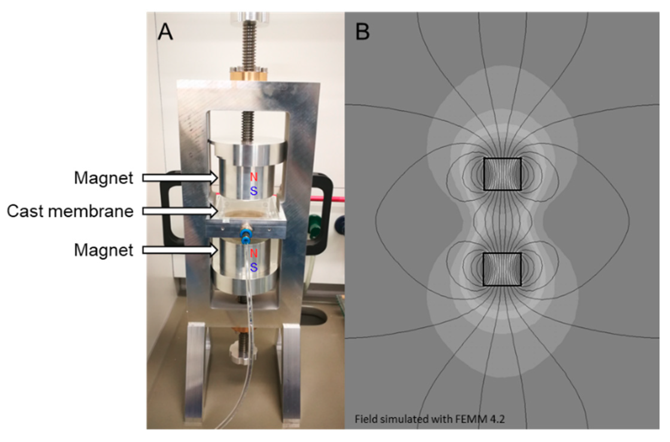
2.3.3. Magnetically Aligned m–ZIF−8/Matrimid MMMs

Magnetically aligned m–ZIF−8/Matrimid MMMs were made similarly to their homogeneous counterpart, where the only difference is the first day of the solvent evaporation. For the homogenous MMM preparation, solvent evaporation in a nitrogen box from the cast polymer solution forms the membrane, whereas for the preparation of the aligned MMMs the nitrogen box was placed in the middle of a permanent magnetic field for one day (Figure 1A). To prevent excessive m–ZIF−8 migration, an aluminum ring (d = 25 mm) was placed in the center of the alignment setup. After one day of solidification in the magnetic field, the membrane was placed in a normal nitrogen box and the previously mentioned drying procedure was followed. This approach of the MOF alignment in MMMs should also be suitable for extension to other types of MOFs and matrices. However, if the MOF contains a one-dimensional pore system, other strategies, such as exterior decoration with Fe3O4, should be considered, as the incorporation of Fe3O4 in a one-dimensional system might result in pore blocking. The obtained 10 and 20 wt.% aligned m–ZIF−8/Matrimid MMMs are abbreviated to 10 wt.% Al and 20 wt.% Al, respectively. Higher weight percentages of m–ZIF−8/Matrimid were also attempted to be aligned, but because of the high M–ZIF−8 volume fraction this did not result in defect free membranes.
The magnetic field was created by two N45 grade permanent magnets (d = 70 mm, h = 60 mm, Nb-Fe-B axially magnetized). The magnetic field strength in the middle of the magnets was 0.22 T when the gap between the magnets was set to 80 mm. The authors are aware that the obtained magnetic field is non-homogeneous, i.e., the field strength decreases from the middle point towards the outer parts of the setup (Figure 1B). However, experiments were also performed in homogeneous magnetic fields created by an electromagnet, but the heat generated by the coils of the electromagnet interfered with the solidification process.

2.4. Characterization

The crystal structure of Fe3O4, ZIF−8 and m–ZIF−8 was analyzed by X-ray diffraction (XRD) using a Rigaku Miniflex 600 (Wilmington, MA, USA) (15 mA, 40 kV, Cu Kα radiation (λ = 1.5406 Å)) in the 2 θ range from 2° to 80° with a scanning rate of 0.5°/min.
The Brunauer–Emmett–Teller (BET) surface area of Fe3O4, ZIF−8 and m–ZIF−8 was determined by N2 physisorption with a Micromeretics Tristar II (Norcross, GA, USA) at −196 °C (liquid N2). Prior to the measurement, the samples were dried in a vacuum oven at 100 °C and 0 mbar overnight.
The thermal stability of Fe3O4, ZIF−8, m–ZIF−8, Matrimid and the MMMs was investigated with a PerkinElmer (Waltham, MA, USA) TGA 4000 under N2 atmosphere (flow 20 mL/min) from 50 to 800 °C with a heating rate of 20 °C/min.
The external morphology of ZIF−8, m–ZIF−8 and the cross-sections of the MMMs were analyzed by a scanning electron microscope (SEM, JEOL JSM-IT100, Tokyo, Japan). Cross-sections of MMMs were obtained by immersing the membranes in a 50:50 water/isopropanol mixture and subsequently fracturing them after immersion in liquid N2. Prior to the analysis, all samples were sputter coated with a JEOL JFC−2300 HR (Tokyo, Japan) with platinum source.
The elemental composition and dispersion of ZIF−8, m–ZIF−8 and the MMMs were analyzed with energy dispersive X-ray spectroscopy (EDS, JEOL JSM-IT100, Tokyo, Japan). Samples were prepared in the same manner as the SEM analysis.
High pressure gas sorption of N2 and CO2 was performed at 35 °C for ZIF−8, m–ZIF−8, Matrimid and the MMMs (Rubotherm series IsoSORP® sorption instrument, Bochum, Germany). The equipment measures the sorbed weight of the gas with a magnetically suspended balance. Prior to each sorption measurement, the weight and volume of the sample is determined with a helium reference measurement. With the obtained sample weight and volume, the measured sorbed weight is corrected for the buoyancy of the measurement gases according to Equation (1), where mcorrected is the corrected weight (g), mmeasured the measured weight (g), ρgas the density of the measuring gas (g/cm3) and Vsample the sample volume (cm3).
m corrected = m measured + ρ gas · V sample
The single gas permeability of Matrimid and the MMMs for N2 and CO2 was determined at 35 °C in triplo by measuring permeate pressure increase over time in a calibrated volume at pressures ranging from 7 to 27 bar according to Equation (2). In Equation (2), Pi is the permeability of gas species i (Barrer), Δppermeate the increase in permeate pressure (Pa) per time interval Δt (s), Vc the calibrated permeate volume (m3), R the gas constant (J/(K∙mol)), T the permeate temperature (K), Vm the molar volume at STP (cm3/mol), L the membrane thickness (cm), A the membrane area (cm2) and Δp the transmembrane pressure (cmHg).
P i = Δ p permeate · V c · V m · L · 10 10 Δ t · R · T · A · Δ p
Prior to each single gas permeation measurement, the membranes were first conditioned for 8 hr at 35 °C and 2 bar N2. Hereafter, first, the N2 single gas permeation measurements were performed. Then, the CO2 single gas permeation measurements were performed, since the CO2 measurements plasticize the membranes. The ideal CO2/N2 selectivity, αCO2/N2 (−), was calculated according to Equation (3).
α CO 2 / N 2 = P CO 2 / P N 2
The CO2 diffusion coefficient of Matrimid and the MMMs was determined according to Equation (4), where D is the CO2 diffusion coefficient (cm2/s), P the CO2 permeability (Barrer) and S the CO2 solubility coefficient (cm3 STP/(cm3·cmHg)). The permeability was experimentally determined by permeation experiments whereas the CO2 solubility coefficient was experimentally obtained by the high pressure sorption measurements using a magnetic suspension balance.
D = P / S

3. Results and Discussion

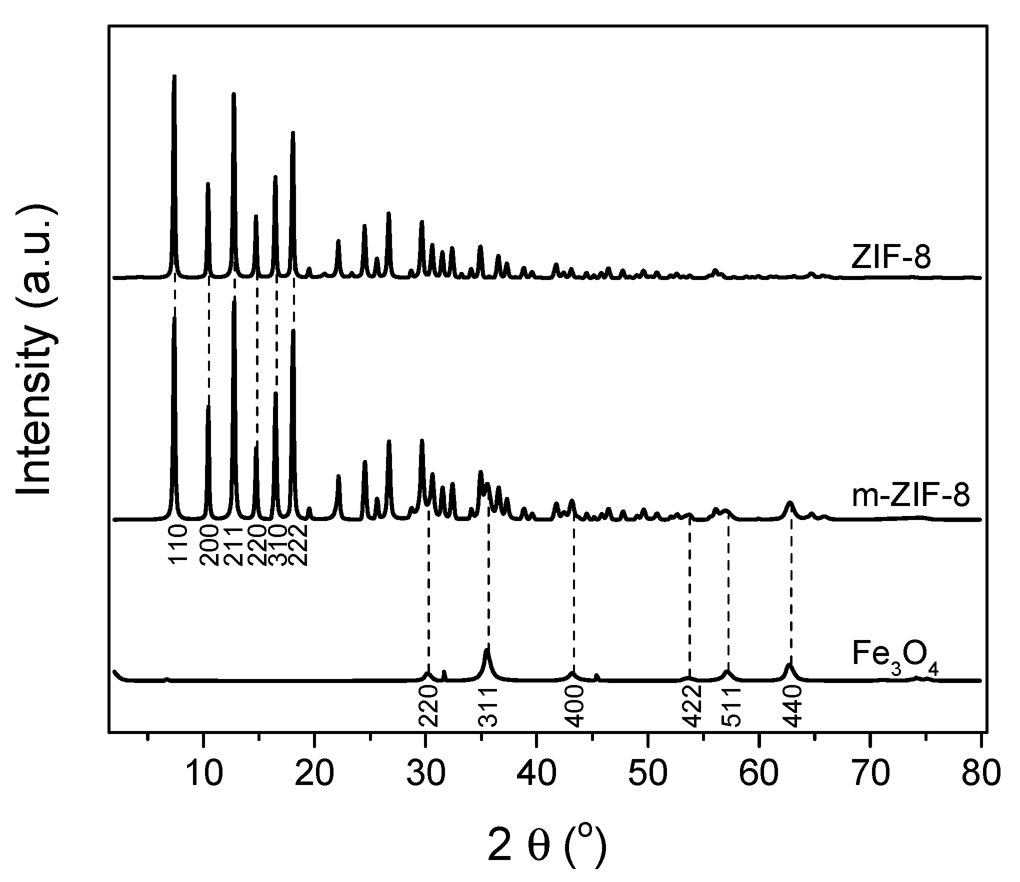
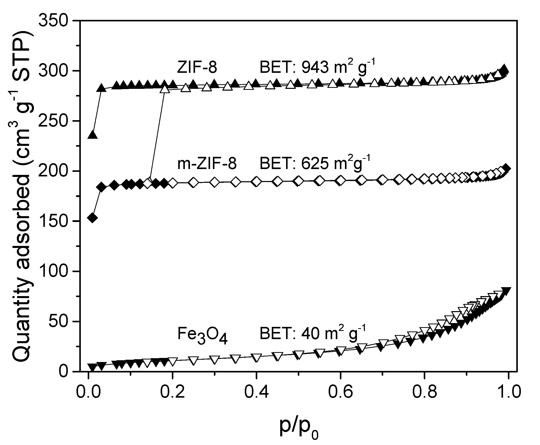
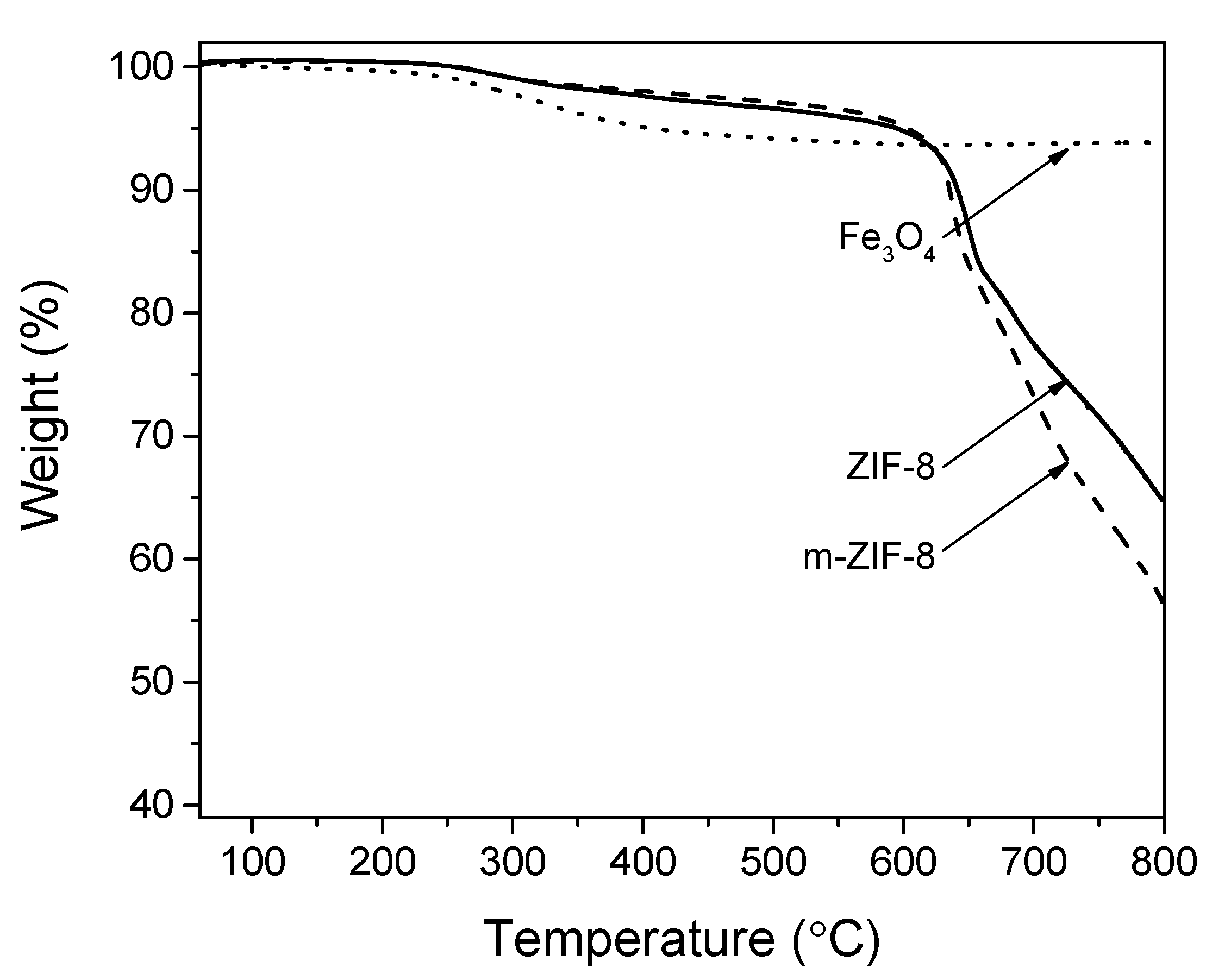
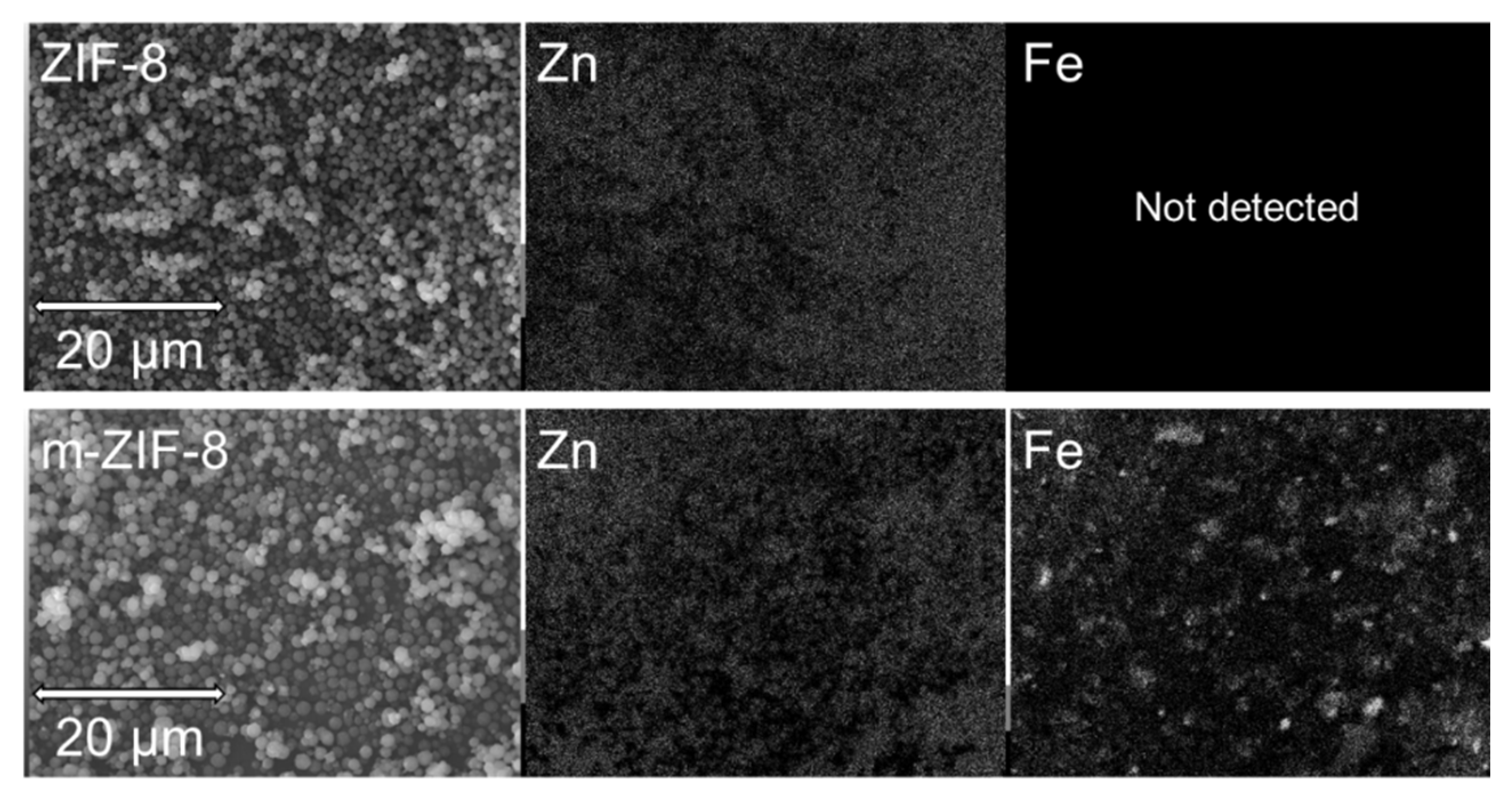
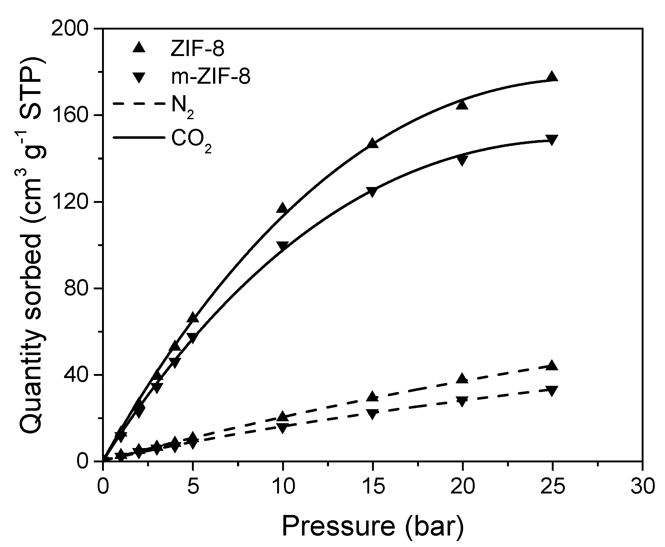
3.1. ZIF−8, m–ZIF−8 and Fe3O4 Analysis

The XRD patterns (Figure 2) show the typical diffraction peaks for both Fe3O4 and ZIF−8. The typical diffraction peaks of both materials are in agreement with the crystal structures found in literature [16,40]. It is clear that the diffraction pattern of m–ZIF−8 shows both the diffraction peaks of ZIF−8 and Fe3O4, which means that the crystal structures of both particles are present in the composite m–ZIF−8 crystal. The ratio of the (211) ZIF−8 peak and the (440) Fe3O4 peak in m–ZIF−8 is higher than the ratio found in literature for ZIF−8/Fe3O4 composites where a significant lower relative amount of Fe3O4 is used in the synthesis mixture [19,21]. On the other hand, the peak ratio of m–ZIF−8 is lower than the ratio found in literature for ZIF/Fe3O4 composites, where the Fe3O4 particle size was significantly bigger [20]. This observation indicates that a considerable amount of Fe3O4 nanoparticles is present in the m–ZIF−8 crystals.
The influence of Fe3O4 incorporation in ZIF−8 on the N2 adsorption is visible in Figure 3. The BET surface area of 943 m2/g of ZIF−8 is comparable to BET surfaces areas reported in literature for ZIF−8 aqueous syntheses at room temperature and confirms the presence of permanent microporous system [14,41]. The BET surface area of m–ZIF−8 (625 m2/g) is clearly lowered by the presence of non-microporous Fe3O4 (40 m2/g) in comparison with pure ZIF−8, i.e., a decrease of 33.7%. ZIF−8/Fe3O4 composites with relatively lower amounts of Fe3O4 in the synthesis mixture show less decrease in surface area [21].
ZIF−8, m–ZIF−8 and Fe3O4 show excellent thermal stability (Figure 4). Incorporation of highly stable Fe3O4 does not affect the degradation temperature of m–ZIF−8 in comparison with ZIF−8. Both ZIF−8 and m–ZIF−8 show a degradation temperature of approximately 600 °C. The small weight loss of ZIF−8 and m–ZIF−8 from 250 to 600 °C is attributed to partial carbonization of entrapped guest molecules, e.g., residual 2-methylimidazole [10].
SEM/EDS analysis of the morphology and elemental composition of ZIF−8 and m–ZIF−8 shows two clear differences between the reference and the magnetized ZIF−8 samples (Figure 5). First, the particle size and range of particle size is increased when Fe3O4 is added to the synthesis mixture of ZIF−8. The ZIF−8 particle size from ranges 0.6 to 1 µm and the m–ZIF−8 particle size ranges from 1 to 1.6 µm. Apparently, the presence Fe3O4 in the m–ZIF−8 synthesis acts as nucleation point, which causes a slightly increased particle size. Secondly, and obviously, no Fe is detected by EDS for ZIF−8 and Fe is detected for the m–ZIF−8.
The effect of the incorporation of Fe3O4 on the N2 and CO2 sorption in m–ZIF−8 is shown in Figure 6 and confirms the observation made for the decrease in BET surface area of m–ZIF−8. Since Fe3O4 has no microporosity, a decrease in both N2 and CO2 sorption is observed when Fe3O4 is incorporated in ZIF−8. The sorption of N2 in ZIF−8 and m–ZIF−8 shows Henry sorption behavior, since almost linear sorption behavior is observed. On the other hand, Langmuir sorption behavior is observed for CO2 in both ZIF types, since the slope of sorption decreases over the whole pressure range. Clearly, higher quantities of CO2 are sorbed in both ZIF structures than N2. This indicates that the sorption of CO2 is thermodynamically favored over N2 sorption, which was also observed for another ZIF type [42]. Moreover, the observed sorption ratio of the two gases corresponds with simulated ratios of sorption of ZIF−8 at 25 °C [43].

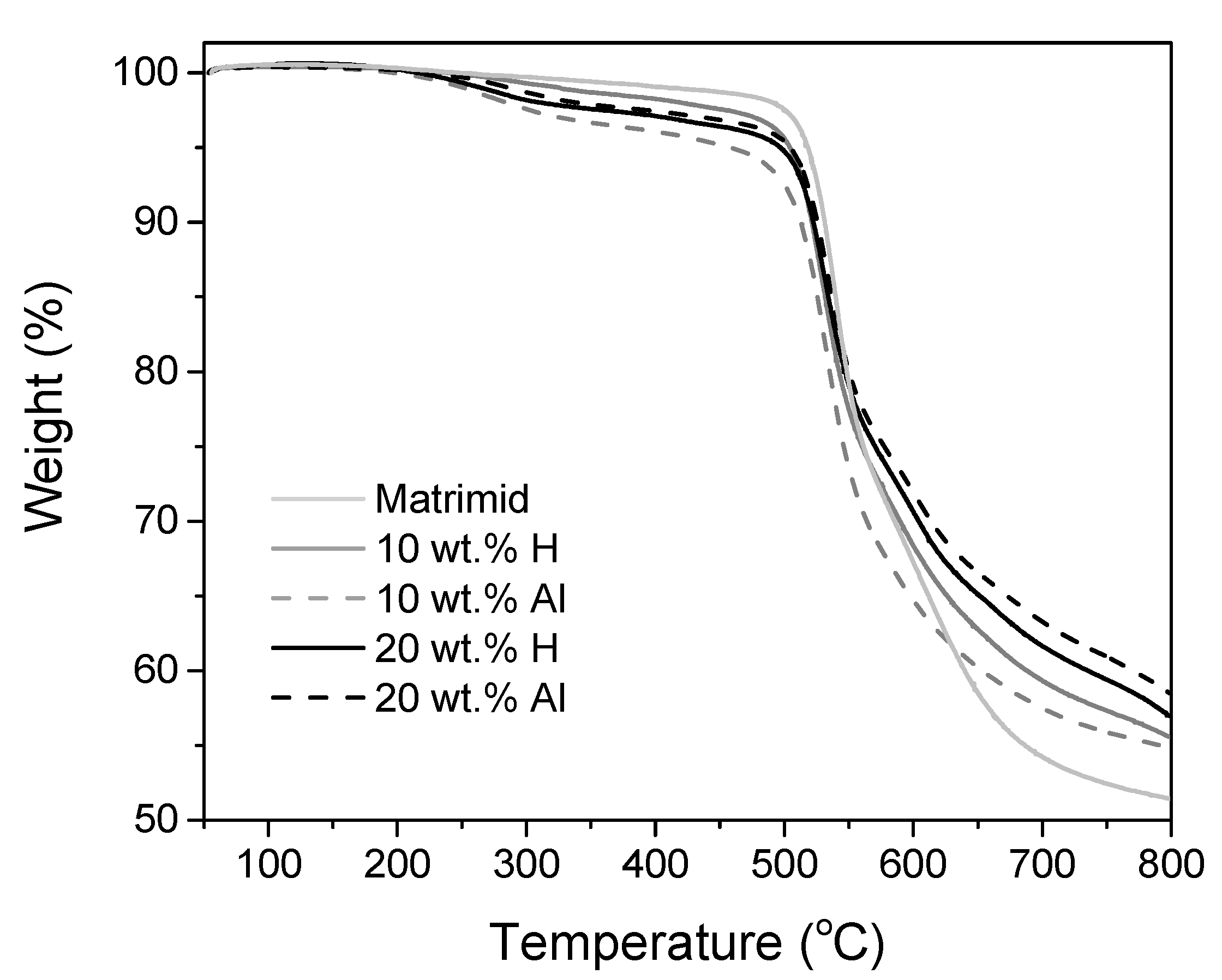
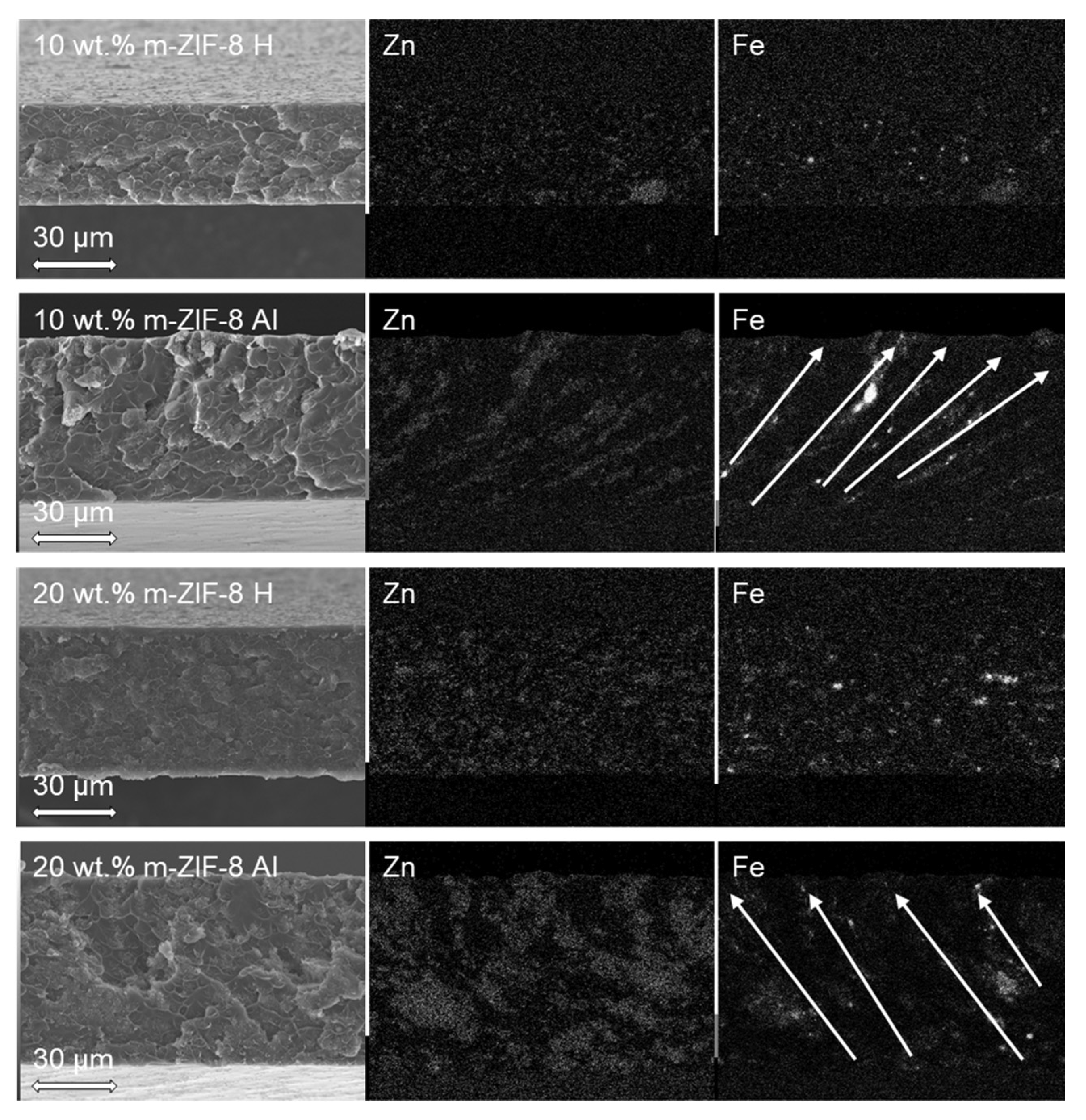
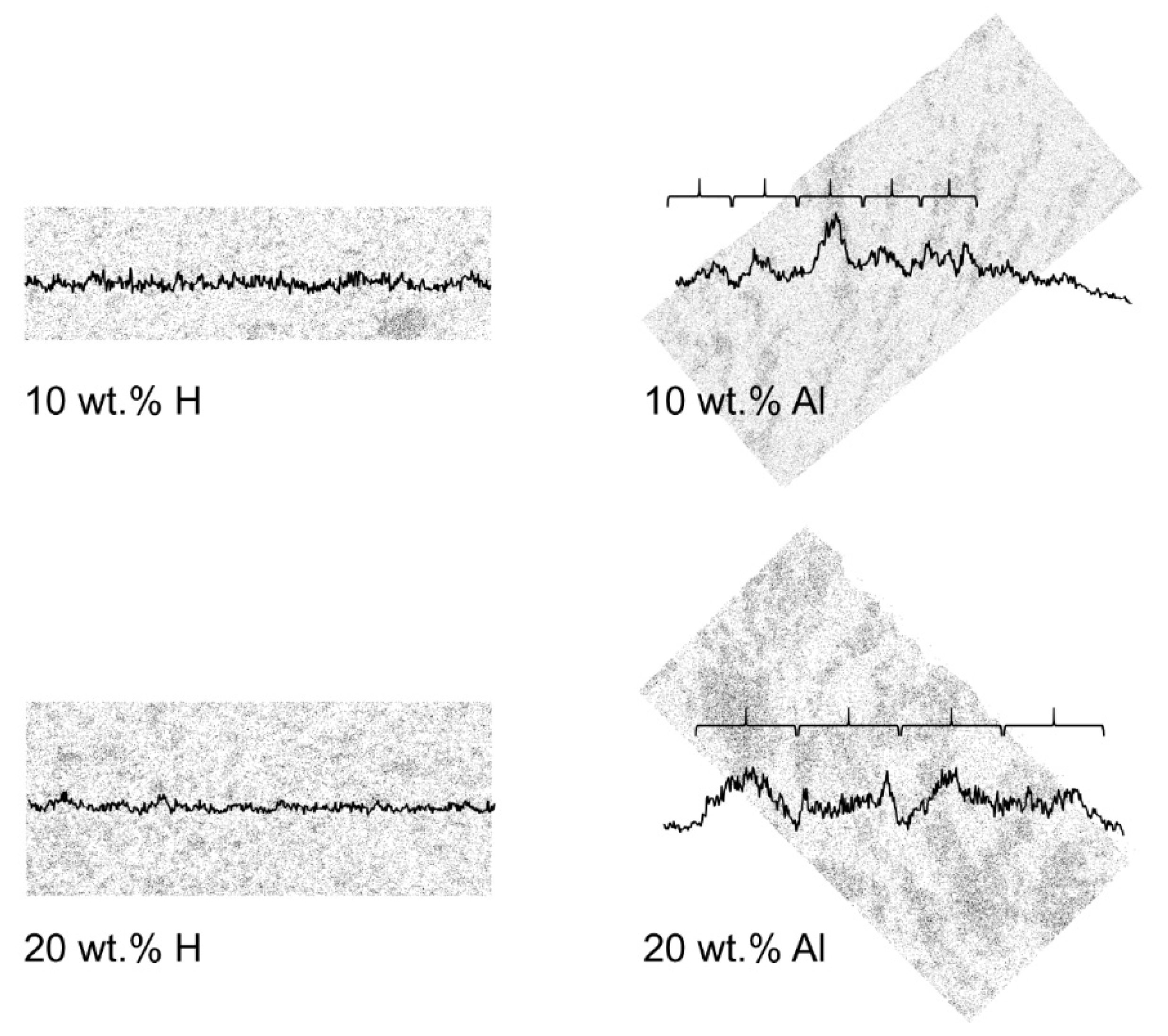
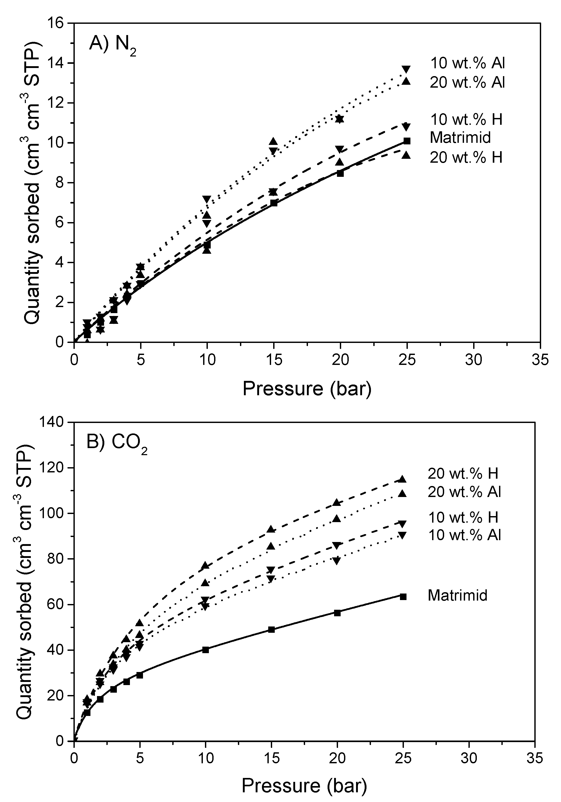
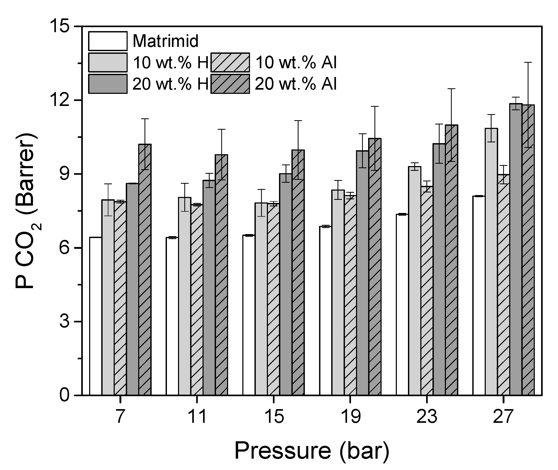
3.2. Membrane Analysis

TGA confirms that the drying method was sufficient for Matrimid and the MMMs (Figure 7). The membranes contained no solvent, since no weight loss observed in the trajectory from approximately 150 to 200 °C (boiling point DMF = 153 °C). All membranes have a degradation temperature of approximately 500 °C. The degradation temperature of m–ZIF−8 (600 °C, Figure 4) is 100 °C higher in comparison with Matrimid that has a degradation temperature of 500 °C (Figure 7). Since the MMMs contain at least 80 wt.% Matrimid, the difference between pure Matrimid and the MMMs is marginally visible.
The morphology and elemental distribution of cross-sections of the homogeneous and aligned MMMs are shown in Figure 8.
Both the 10 wt.% H and 20 wt.% H MMMs show that m–ZIF−8 is evenly distributed throughout the matrix, i.e., the characteristic elements Zn and Fe are evenly distributed throughout both the membranes. On the other hand, both the 10 wt.% Al and 20 wt.% Al MMMs show that lines and enriched regions of Zn and Fe are present through the matrix. This confirms that m–ZIF−8 is effectively clustered and aligned in the magnetic field lines (indicated by the arrows in Figure 8). Compact lines of Zn and Fe are present in the 10 wt.% Al MMM, which partially reach from the bottom to the top of the membrane. The 20 wt.% Al MMM shows that increasing the amount of incorporated m–ZIF−8 results in broader aligned pathways in comparison with the 10 wt.% Al MMM. Thus, increasing the additive content during alignment results in a further increased interconnectivity between m–ZIF−8 particles. Similar morphologies and Fe mappings are reported for other composites with magnetically aligned particles [35,36]. Alignment of m–ZIF−8 increases thickness of the MMMs, since the m–ZIF−8 particles are attracted towards the magnetic field lines. The thickness increases with 24 µm for the 10 wt.% MMMs (L10 wt.% H = 36 µm, L10 wt.% Al = 60 µm) and with 16 µm for the 20 wt.% MMMs (L20 wt.% H = 54 µm, L20 wt.% Al = 70 µm). It is visible for the aligned MMMs that the used magnetic field is inhomogeneous, since alignment of the MMMs is not perpendicular to the membrane surface, which increases the MOF path length through the matrix.
Alignment and clustering of m–ZIF−8 in the MMMs is further substantiated by analyzing the particle count of Zn (Figure 9).
In Figure 9, the vertical particle count of the respective MMM is visualized by the graph which overlays the Zn EDS map. Moreover, the aligned MMMs are rotated such that the direction of alignment, as indicated by the arrows in Figure 8, is positioned vertically. Both the 10 and 20 wt.% H MMMs show that the particle count throughout the membranes is evenly distributed, since the particle count graphs are approximately horizontal. On the other hand, clear peaks are present in the particle graphs of the 10 and 20 wt.% Al MMMs that occur periodically (indicated by the curly brackets in Figure 9). As stated previously, the aligned pathways and enriched regions in the 10 wt.% Al MMM are narrower and smaller than the 20 wt.% Al MMM, which is visualized by the smaller periodicity of the 10 wt.% MMM (i.e., the smaller curly brackets). Lastly, the peaks of the particle count graphs are more delicately pronounced in the 10 wt.% Al MMM than in the 20 wt.% Al MMM, which is attributed to the increased brittleness of the locally m–ZIF−8 aligned pathway. As an increasing MOF content in MMMs results in an increased brittleness, it is more difficult to keep an aligned m–ZIF−8 path intact when the sample is cryogenically fractured for the SEM/EDS analysis [30,44].
N2 and CO2 sorption isotherms of Matrimid and the MMMs are shown in Figure 10.
The sorption of N2 in Matrimid and the MMMs exhibits predominantly Henry sorption behavior. It is notable that the aligned MMMs have an increased sorption of N2, with respect to both Matrimid and the homogeneous MMMs. Since m–ZIF−8 (Figure 6) has a higher N2 uptake than Matrimid (Figure 10), it is expected that all MMMs should have an increased N2 uptake. However, this is only observed for the aligned MMMs, which means that the N2 sorption sites of m–ZIF−8 in the aligned MMMs are more readily accessible than in the homogeneous MMMs. Therefore, it is concluded that ZIF−8 alignment and local enrichment effectively decrease the polymer content between the MOF particles. The uptake of CO2 in Matrimid and the MMMs occurs according to the dual-mode sorption model (i.e., Henry and Langmuir sorption. The aligned MMMs show a lower CO2 sorption than the homogeneous MMMs at elevated pressures. This decrease in solubility is ascribed to increased CO2 uptake at the ZIF/matrix interface, since it was demonstrated that at elevated CO2 pressure (starting at 10 bar) matrix derigidification at the interface causes an increased CO2 uptake [45]. The aligned and enriched MMMs have a decreased polymer content between the MOF particles, causing a decreased CO2 induced rigidification at elevated pressures. This results in a slightly lowered CO2 sorption relative to the homogeneous MMM. Increasing the m–ZIF−8 content in the MMMs results in a higher CO2 sorption, due to the high CO2 sorption capacity of m–ZIF−8 (Figure 6) in comparison with Matrimid (Figure 10).
The influence of m–ZIF−8 content in the MMMs and effect of alignment on the CO2 single gas permeability is shown in Figure 11.
The CO2 permeability of Matrimid increases from 6.4 Barrer at 11 bar to 8.1 Barrer at 27 bar once its plasticization pressure is reached, which lies between 10 and 12 bar CO2 pressure [46]. The Matrimid CO2 permeability is slightly lower than values reported elsewhere in literature [29,44,46]. This observation is attributed to the difference in annealing protocol, which strongly influences the permeability [29]. The incorporation of 10 wt.% m–ZIF−8 results in an increased CO2 permeability of the homogeneous and aligned MMMs relative to pure Matrimid. Counterintuitively, since pure ZIF−8 has a high CO2 permeability, this increased CO2 permeability is caused by an increased CO2 solubility, while the CO2 diffusivity decreases (Table 1) [25]. This decrease in diffusivity is ascribed to matrix rigidification around the MOF particles [46,47]. Alignment at 10 wt.% m–ZIF−8 content does not influence the CO2 permeability, with respect to the homogeneous MMM. The CO2 permeability of both 10 wt.% MMMs starts to increase from 15 bar CO2 feed pressure, i.e., plasticization occurs. This increased plasticization pressure in MOF/Matrimid MMMs is in agreement with literature [46].
Further increasing the m–ZIF−8 content resulted in an increased CO2 permeability. For both the 20 wt.% H and Al MMMs, a further increase in CO2 solubility is observed (Table 1). However, in contrast with the 10 wt.% MMMs, a clear difference in diffusivity is visible for the 20 wt.% MMMs. The diffusivity of the 20 wt.% H MMM is decreased with respect to the 10 wt.% H MMM, which can be attributed to further matrix rigidification. On the other hand, the diffusivity of the 20 wt.% Al MMM increased, with respect to the 10 wt.% Al MMM. Even though the alignment direction in the 20 wt.% Al MMM was not perfectly parallel to the permeation path, it can be concluded that alignment and local MOF enrichment successfully increased the CO2 diffusivity and subsequently the permeability of the 20 wt.% MMM, with respect to the 20 wt.% H MMM. A maximum increase of 19% in CO2 permeability was observed at 7 bar, which indicates that alignment is predominantly beneficial below the plasticization temperature. Thus, the performance of MMMs can be improved by controlling the spatial distribution of the MOF additive.
The ideal CO2/N2 selectivity of Matrimid, 10 wt.% H, 10 wt.% Al, 20 wt.% H and 20 wt.% Al MMMs as function of pressure are shown in Figure 12.
At low feed pressure, pure Matrimid has a higher ideal selectivity than the MMMs. This means that m–ZIF−8 enhances next to the CO2 permeability (Figure 11) also the N2 permeability, but the relative increase in N2 permeability is higher than the relative increase in CO2 permeability. Since single crystal ZIF−8 has a selectivity which is at maximum equal to the selectivity of Matrimid, it can be concluded that non idealities between the matrix-MOF interface are present [25]. Nonetheless, aligning m–ZIF−8 has a positive response on the permeability without compromising the ideal selectivity up to 15 bar, with respect to the homogeneous MMMs. The facts that overall, no significant differences are present between the ideal selectivity of the homogeneous and aligned MMMs (Figure 12) and that the solubility of N2 is higher in the aligned MMMs than in the homogeneous MMMs (Figure 10) prove that the aligned MMMs enhance the CO2 diffusivity more than the N2 diffusivity, relative to the homogeneous MMMs. It is argued that this enhanced CO2 diffusivity is caused by the different kinetic diameters of CO2 (3.30 Å) and N2 (3.64 Å) and the effect of the aligned and enriched ZIF−8 pathways. Since the pore aperture of ZIF−8 is 3.4 Å, CO2 (with a kinetic diameter smaller than the ZIF−8 pore aperture) will diffuse more easily through the MOF than N2 (with a kinetic diameter bigger than the ZIF−8 pore aperture). Moreover, the increased ZIF−8 interconnectivity in the aligned MMMs causes preferential permeation through the MOF relative to the matrix, since the permeability of pure ZIF−8 is significantly higher than the permeability of Matrimid. As a result, the CO2 diffusivity will thus relatively be promoted more than the N2 diffusivity in the aligned MMMs than in the homogeneous MMMs. With increasing CO2 pressure, the effect of plasticization on the selectivity is observed. Due to the plasticization induced increased CO2 permeability, the ideal selectivity of all membranes increase (an opposite trend is expected for mixed gas permeation experiments above the plasticization pressure). Clearly, Matrimid plasticizes most pronounced at 11 to 15 bar feed pressure, while the MMM start to plasticize at 15 bar feed pressure.

4. Conclusions

ZIF−8 was successfully magnetized by the incorporation of Fe3O4. The presence of Fe3O4 in m–ZIF−8 showed a decrease in BET surface area and CO2 and N2 solubility, with respect to pure ZIF−8. Alignment of m–ZIF−8 in Matrimid was visually present by SEM-EDS analysis and showed clear m–ZIF−8 enriched pathways and regions in the aligned and clustered MMMs both at 10 and 20 wt.%. Due to the limitation of a permanent magnetic field lines, it was observed that the alignment was not fully perpendicular to the membrane surface, which increased the effective length of the m–ZIF−8 pathway through the MMM. At 20 wt.% m–ZIF−8 incorporation in Matrimid, alignment was proven to increase the CO2 permeability at maximum with 19% at 7 bar, while no CO2/N2 selectivity loss of was observed, with respect to the homogeneous 20 wt.% MMM. Therefore, it was concluded that at 20 wt.% m–ZIF−8 content, the alignment results in sufficiently m–ZIF−8 enriched aligned clusters throughout the MMM matrix that established an increase in diffusivity and subsequently permeability. The use of a homogeneous magnetic field will straighten the percolation path and will result in a further improved membrane performance at even lower weight percentages of magnetic MOFs. Nonetheless, this paper shows that alignment of MOF particles throughout the matrix creating permeation highways is beneficial to enhance the CO2 permeability without adversely affecting the selectivity.

Author Contributions

Conceptualization, M.v.E., Z.B. and K.N.; methodology, M.v.E.; formal analysis, M.v.E., E.M. and M.H.; investigation, M.v.E., E.M. and M.H.; writing—original draft preparation, M.v.E.; writing—review and editing, M.H., Z.B. and K.N.; visualization, M.v.E.; supervision, Z.B. and K.N.; project administration, K.N.; funding acquisition, K.N. All authors have read and agreed to the published version of the manuscript.

Funding

This work is part of the research programme ‘Fuel feedstock production by a combined approach of controlled plasma conversion and membrane separation’ with project number 13584 which is partly financed by the Dutch Research Council (NWO).Membranes 10 00155 i001

Acknowledgments

The authors want to thank Peter Lipman and Wendy Liu from the Eindhoven University of Technology for their help with the BET and XRD measurements, respectively.

Conflicts of Interest

The authors declare no conflict of interest.

References

  1. Ismail, A.F.; Khulbe, K.C.; Matsuura, T. Gas Separation Membranes: Polymeric and Inorganic; Springer: Heidelberg, Germany, 2015; ISBN 9783319010953. [Google Scholar]
  2. Robeson, L.M. Correlation of separation factor versus permeability for polymeric membranes. J. Memb. Sci. 1991, 62, 165–185. [Google Scholar] [CrossRef]
  3. Robeson, L.M. The upper bound revisited. J. Memb. Sci. 2008, 320, 390–400. [Google Scholar] [CrossRef]
  4. Biswal, B.P.; Chaudhari, H.D.; Banerjee, R.; Kharul, U.K. Chemically Stable Covalent Organic Framework (COF)-Polybenzimidazole Hybrid Membranes: Enhanced Gas Separation through Pore Modulation. Chem. Eur. J. 2016, 22, 4695–4699. [Google Scholar] [CrossRef] [PubMed]
  5. Thür, R.; Van Velthoven, N.; Slootmaekers, S.; Didden, J.; Verbeke, R.; Smolders, S.; Dickmann, M.; Egger, W.; De Vos, D.; Vankelecom, I.F.J. Bipyridine-based UiO−67 as novel filler in mixed-matrix membranes for CO2-selective gas separation. J. Memb. Sci. 2019, 576, 78–87. [Google Scholar] [CrossRef]
  6. Kertik, A.; Wee, L.H.; Pfannmöller, M.; Bals, S.; Martens, J.A.; Vankelecom, I.F.J. Highly selective gas separation membrane using in situ amorphised metal-organic frameworks. Energy Environ. Sci. 2017, 10, 2342–2351. [Google Scholar] [CrossRef]
  7. Yuan, J.; Zhu, H.; Sun, J.; Mao, Y.; Liu, G.; Jin, W. Novel ZIF−300 Mixed-Matrix Membranes for Efficient CO2 Capture. ACS Appl. Mater. Interfaces 2017, 9, 38575–38583. [Google Scholar] [CrossRef]
  8. Jeazet, H.B.T.; Staudt, C.; Janiak, C. Metal–organic frameworks in mixed-matrix membranes for gas separation. Dalt. Trans. 2012, 41, 14003–14027. [Google Scholar] [CrossRef]
  9. Li, H.; Wang, K.; Sun, Y.; Lollar, C.T.; Li, J.; Zhou, H.C. Recent advances in gas storage and separation using metal–organic frameworks. Mater. Today 2018, 21, 108–121. [Google Scholar] [CrossRef]
  10. Park, K.S.; Ni, Z.; Côté, A.P.; Choi, J.Y.; Huang, R.; Uribe-Romo, F.J.; Chae, H.K.; O’Keeffe, M.; Yaghi, O.M. Exceptional chemical and thermal stability of zeolitic imidazolate frameworks. Proc. Natl. Acad. Sci. USA 2006, 103, 10186–10191. [Google Scholar] [CrossRef] [Green Version]
  11. Yuan, S.; Feng, L.; Wang, K.; Pang, J.; Bosch, M.; Lollar, C.; Sun, Y.; Qin, J.; Yang, X.; Zhang, P.; et al. Stable Metal-Organic Frameworks: Design, Synthesis, and Applications. Adv. Mater. 2018, 30, 1–35. [Google Scholar] [CrossRef] [Green Version]
  12. Phan, A.; Doonan, C.J.; Uribe-Romo, F.J.; Knobler, C.B.; O’Keeffe, M.; Yaghi, O.M. Synthesis, Structure, and Carbon Dioxide Capture Properties of Zeolitic Imidazolate Frameworks. Acc. Chem. Res. 2010, 43, 58–67. [Google Scholar] [CrossRef]
  13. Chen, B.; Yang, Z.; Zhu, Y.; Xia, Y. Zeolitic imidazolate framework materials: Recent progress in synthesis and applications. J. Mater. Chem. A 2014, 2, 16811–16831. [Google Scholar] [CrossRef]
  14. Pan, Y.; Liu, Y.; Zeng, G.; Zhao, L.; Lai, Z. Rapid synthesis of zeolitic imidazolate framework−8 (ZIF−8) nanocrystals in an aqueous system. Chem. Commun. 2011, 47, 2071–2073. [Google Scholar] [CrossRef]
  15. Tanaka, S.; Kida, K.; Okita, M.; Ito, Y.; Miyake, Y. Size-Controlled synthesis of zeolitic imidazolate framework−8 (ZIF−8) crystals in an aqueous system at room temperature. Chem. Lett. 2012, 41, 1337–1339. [Google Scholar] [CrossRef]
  16. Cravillon, J.; Nayuk, R.; Springer, S.; Feldhoff, A.; Huber, K.; Wiebcke, M. Controlling Zeolitic Imidazolate Framework Nano- and Microcrystal Formation: Insight into Crystal Growth by Time-Resolved In Situ Static Light Scattering. Chem. Mater. 2011, 23, 2130–2141. [Google Scholar] [CrossRef]
  17. Lee, Y.R.; Jang, M.S.; Cho, H.Y.; Kwon, H.J.; Kim, S.; Ahn, W.S. ZIF−8: A comparison of synthesis methods. Chem. Eng. J. 2015, 271, 276–280. [Google Scholar] [CrossRef]
  18. Bustamante, E.L.; Fernández, J.L.; Zamaro, J.M. Influence of the solvent in the synthesis of zeolitic imidazolate framework−8 (ZIF−8) nanocrystals at room temperature. J. Colloid Interface Sci. 2014, 424, 37–43. [Google Scholar] [CrossRef]
  19. Lu, G.; Li, S.; Guo, Z.; Farha, O.K.; Hauser, B.G.; Qi, X.; Wang, Y.; Wang, X.; Han, S.; Liu, X.; et al. Imparting functionality to a metal-organic framework material by controlled nanoparticle encapsulation. Nat. Chem. 2012, 4, 310–316. [Google Scholar] [CrossRef] [PubMed]
  20. Zhang, T.; Zhang, X.; Yan, X.; Kong, L.; Zhang, G.; Liu, H.; Qiu, J.; Yeung, K.L. Synthesis of Fe3O4@ZIF−8 magnetic core-shell microspheres and their potential application in a capillary microreactor. Chem. Eng. J. 2013, 228, 398–404. [Google Scholar] [CrossRef]
  21. Jiang, X.; Chen, H.Y.; Liu, L.L.; Qiu, L.G.; Jiang, X. Fe3O4 embedded ZIF−8 nanocrystals with ultra-high adsorption capacity towards hydroquinone. J. Alloy. Compd. 2015, 646, 1075–1082. [Google Scholar] [CrossRef]
  22. Venna, S.R.; Carreon, M.A. Metal organic framework membranes for carbon dioxide separation. Chem. Eng. Sci. 2015, 124, 3–19. [Google Scholar] [CrossRef]
  23. Guan, W.; Dai, Y.; Dong, C.; Yang, X.; Xi, Y. Zeolite imidazolate framework (ZIF)-based mixed matrix membranes for CO 2 separation: A review. J. Appl. Polym. Sci. 2020, 48968, 1–13. [Google Scholar] [CrossRef]
  24. Pimentel, B.R.; Parulkar, A.; Zhou, E.; Brunelli, N.A. Zeolitic Imidazolate Frameworks: Next-Generation Materials for Energy-Efficient Gas Separations. ChemSusChem 2014, 7, 3202–3240. [Google Scholar] [CrossRef] [PubMed]
  25. Chen, C.; Ozcan, A.; Yazaydin, A.O.; Ladewig, B.P. Gas permeation through single-crystal ZIF−8 membranes. J. Memb. Sci. 2019, 575, 209–216. [Google Scholar] [CrossRef] [Green Version]
  26. Shahid, S.; Nijmeijer, K.; Nehache, S.; Vankelecom, I.; Deratani, A.; Quemener, D. MOF-mixed matrix membranes: Precise dispersion of MOF particles with better compatibility via a particle fusion approach for enhanced gas separation properties. J. Memb. Sci. 2015, 492, 21–31. [Google Scholar] [CrossRef]
  27. Wang, Z.; Wang, D.; Zhang, S.; Hu, L.; Jin, J. Interfacial Design of Mixed Matrix Membranes for Improved Gas Separation Performance. Adv. Mater. 2016, 28, 3399–3405. [Google Scholar] [CrossRef]
  28. Sánchez-Laínez, J.; Zornoza, B.; Friebe, S.; Caro, J.; Cao, S.; Sabetghadam, A.; Seoane, B.; Gascon, J.; Kapteijn, F.; Le Guillouzer, C.; et al. Influence of ZIF−8 particle size in the performance of polybenzimidazole mixed matrix membranes for pre-combustion CO2 capture and its validation through interlaboratory test. J. Memb. Sci. 2016, 515, 45–53. [Google Scholar] [CrossRef]
  29. Song, Q.; Nataraj, S.K.; Roussenova, M.V.; Tan, J.C.; Hughes, D.J.; Li, W.; Bourgoin, P.; Alam, M.A.; Cheetham, A.K.; Al-Muhtaseb, S.A.; et al. Zeolitic imidazolate framework (ZIF−8) based polymer nanocomposite membranes for gas separation. Energy Environ. Sci. 2012, 5, 8359–8369. [Google Scholar] [CrossRef]
  30. Mahdi, E.M.; Tan, J.C. Mixed-matrix membranes of zeolitic imidazolate framework (ZIF−8)/Matrimid nanocomposite: Thermo-mechanical stability and viscoelasticity underpinning membrane separation performance. J. Memb. Sci. 2016, 498, 276–290. [Google Scholar] [CrossRef]
  31. Cheng, F.; Marshall, E.S.; Young, A.J.; Robinson, P.J.; Bouillard, J.S.G.; Adawi, A.M.; Vermeulen, N.A.; Farha, O.K.; Reithofer, M.R.; Chin, J.M. Magnetic Control of MOF Crystal Orientation and Alignment. Chem. Eur. J. 2017, 23, 15578–15582. [Google Scholar] [CrossRef]
  32. Sharma, A.; Tripathi, B.; Vijay, Y.K. Dramatic Improvement in properties of magnetically aligned CNT/polymer nanocomposites. J. Memb. Sci. 2010, 361, 89–95. [Google Scholar] [CrossRef]
  33. Sharma, A.; Kumar, S.; Tripathi, B.; Singh, M.; Vijay, Y.K. Aligned CNT/Polymer nanocomposite membranes for hydrogen separation. Int. J. Hydrog. Energy 2009, 34, 3977–3982. [Google Scholar] [CrossRef]
  34. Qiao, Z.; Zhao, S.; Wang, J.; Wang, S.; Wang, Z.; Guiver, M.D. A Highly Permeable Aligned Montmorillonite Mixed-Matrix Membrane for CO2 Separation. Angew. Chem. 2016, 128, 9467–9471. [Google Scholar] [CrossRef]
  35. Jung, H.S.; Kwon, S.H.; Choi, H.J.; Jung, J.H.; Kim, Y.G. Magnetic carbonyl iron/natural rubber composite elastomer and its magnetorheology. Compos. Struct. 2016, 136, 106–112. [Google Scholar] [CrossRef]
  36. Yao, J.; Sun, Y.; Wang, Y.; Fu, Q.; Xiong, Z.; Liu, Y. Magnet-induced aligning magnetorheological elastomer based on ultra-soft matrix. Compos. Sci. Technol. 2018, 162, 170–179. [Google Scholar] [CrossRef]
  37. Weber, R.; Orsino, S.; Lallemant, N.; Verlaan, A. Combustion of natural gas with high-temperature air and large quantities of flue gas. Proc. Combust. Inst. 2000, 28, 1315–1321. [Google Scholar] [CrossRef]
  38. Ibbs, T.L.; Underwood, L. A comparison of the behaviour in thermal diffusion of nitrogen and carbon monoxide, and of nitrous oxide and carbon dioxide. Proc. Phys. Soc. 1926, 39, 227–237. [Google Scholar] [CrossRef]
  39. Bongers, W.; Bouwmeester, H.; Wolf, B.; Peeters, F.; Welzel, S.; van den Bekerom, D.; den Harder, N.; Goede, A.; Graswinckel, M.; Groen, P.W.; et al. Plasma-driven dissociation of CO2 for fuel synthesis. Plasma Process. Polym. 2017, 14, 1–8. [Google Scholar] [CrossRef] [Green Version]
  40. Petcharoen, K.; Sirivat, A. Synthesis and characterization of magnetite nanoparticles via the chemical co-precipitation method. Mater. Sci. Eng. B 2012, 177, 421–427. [Google Scholar] [CrossRef]
  41. Nordin, N.A.H.M.; Ismail, A.F.; Mustafa, A.; Murali, R.S.; Matsuura, T. The impact of ZIF−8 particle size and heat treatment on CO2/CH4 separation using asymmetric mixed matrix membrane. RSC Adv. 2014, 4, 52530–52541. [Google Scholar] [CrossRef]
  42. Venkatasubramanian, A.; Navaei, M.; Bagnall, K.R.; McCarley, K.C.; Nair, S.; Hesketh, P.J. Gas Adsorption Characteristics of Metal-Organic Frameworks via Quartz Crystal Microbalance Techniques. J. Phys. Chem. C 2012, 116, 15313–15321. [Google Scholar] [CrossRef]
  43. Chokbunpiam, T.; Fritzsche, S.; Chmelik, C.; Caro, J.; Janke, W.; Hannongbua, S. Gate Opening, Diffusion, and Adsorption of CO2 and N2 Mixtures in ZIF−8. J. Phys. Chem. C 2016, 120, 23458–23468. [Google Scholar] [CrossRef]
  44. Ordoñez, M.J.C.; Balkus, K.J.; Ferraris, J.P.; Musselman, I.H. Molecular sieving realized with ZIF−8/Matrimid® mixed-matrix membranes. J. Memb. Sci. 2010, 361, 28–37. [Google Scholar] [CrossRef]
  45. Balçık, M.; Tantekin-Ersolmaz, S.B.; Ahunbay, M.G. Interfacial analysis of mixed-matrix membranes under exposure to high-pressure CO2. J. Memb. Sci. 2020, 607, 1–10. [Google Scholar] [CrossRef]
  46. Shahid, S.; Nijmeijer, K. Performance and plasticization behavior of polymer-MOF membranes for gas separation at elevated pressures. J. Memb. Sci. 2014, 470, 166–177. [Google Scholar] [CrossRef]
  47. Shahid, S.; Nijmeijer, K. High pressure gas separation performance of mixed-matrix polymer membranes containing mesoporous Fe(BTC). J. Memb. Sci. 2014, 459, 33–44. [Google Scholar] [CrossRef]
Figure 1. (A) The magnetic alignment setup. The nitrogen box is placed in the middle of two magnets from which both their magnetic north pole is faced upwards. (B) Simulation of the obtained non-homogeneous magnetic field lines with a gap of 80 mm between the magnets.
Membranes 10 00155 g001
Figure 2. XRD patterns of ZIF−8, m–ZIF−8 and Fe3O4.
Membranes 10 00155 g002
Figure 3. N2 adsorption isotherms (filled = adsorption, open = desorption) and BET surface areas of ZIF−8, m–ZIF−8 and Fe3O4.
Membranes 10 00155 g003
Figure 4. Thermal stability of ZIF−8, m–ZIF−8 and Fe3O4.
Membranes 10 00155 g004
Figure 5. SEM images of ZIF−8 and m–ZIF−8 and their corresponding EDS maps of Zn and Fe.
Membranes 10 00155 g005
Figure 6. N2 (dash) and CO2 (solid) sorption isotherms of ZIF−8 (triangle up) and m–ZIF−8 (triangle down).
Membranes 10 00155 g006
Figure 7. Thermal stability of Matrimid, 10 wt.% H, 10 wt.% Al, 20 wt.% H and 20 wt.% Al MMMs.
Membranes 10 00155 g007
Figure 8. SEM images of 10 wt.% H, 10 wt.% Al, 20 wt.% H and 20 wt.% Al MMMs and their corresponding EDS maps of Zn and Fe, the arrows indicate the direction of alignment. All membranes have glass plate side at the bottom side of the SEM image and EDS mapping.
Membranes 10 00155 g008
Figure 9. Particle count of Zn EDS maps (color inversed with respect to Figure 8) of 10 wt.% H, 10 wt.% Al, 20 wt.% H and 20 wt.% Al MMMs. The curly brackets display the approximate periodicity of the alignment.
Membranes 10 00155 g009
Figure 10. (A) N2 and (B) CO2 sorption of Matrimid, 10 wt.% H, 10 wt.% Al, 20 wt.% H and 20 wt.% Al MMMs.
Membranes 10 00155 g010
Figure 11. Single gas CO2 permeability (PCO2) of Matrimid, 10 wt.% H, 10 wt.% Al, 20 wt.% H and 20 wt.% Al MMMs as function of pressure.
Membranes 10 00155 g011
Figure 12. Ideal CO2/N2 selectivity of Matrimid, 10 wt.% H, 10 wt.% Al, 20 wt.% H and 20 wt.% Al MMMs as function of pressure.
Membranes 10 00155 g012
Table 1. CO2 Permeability (P), solubility coefficient (S) and diffusion coefficient (D) of Matrimid, 10 wt.% H, 10 wt.% Al, 20 wt.% H and 20 wt.% Al MMMs at 11 bar.
MembraneP
[Barrer]
S
[cm3 STP/(cm3 · cmHg)]
D
[10−8 cm2/s]
Matrimid6.40.0511.3
10 wt.% H8.10.0781.0
10 wt.% Al7.80.0741.0
20 wt.% H8.70.0960.9
20 wt.% Al9.80.0871.1

