Graphene-based Membranes for H2 Separation: Recent Progress and Future Perspective


Abstract
:
1. Introduction
2. Graphene-Based Membrane
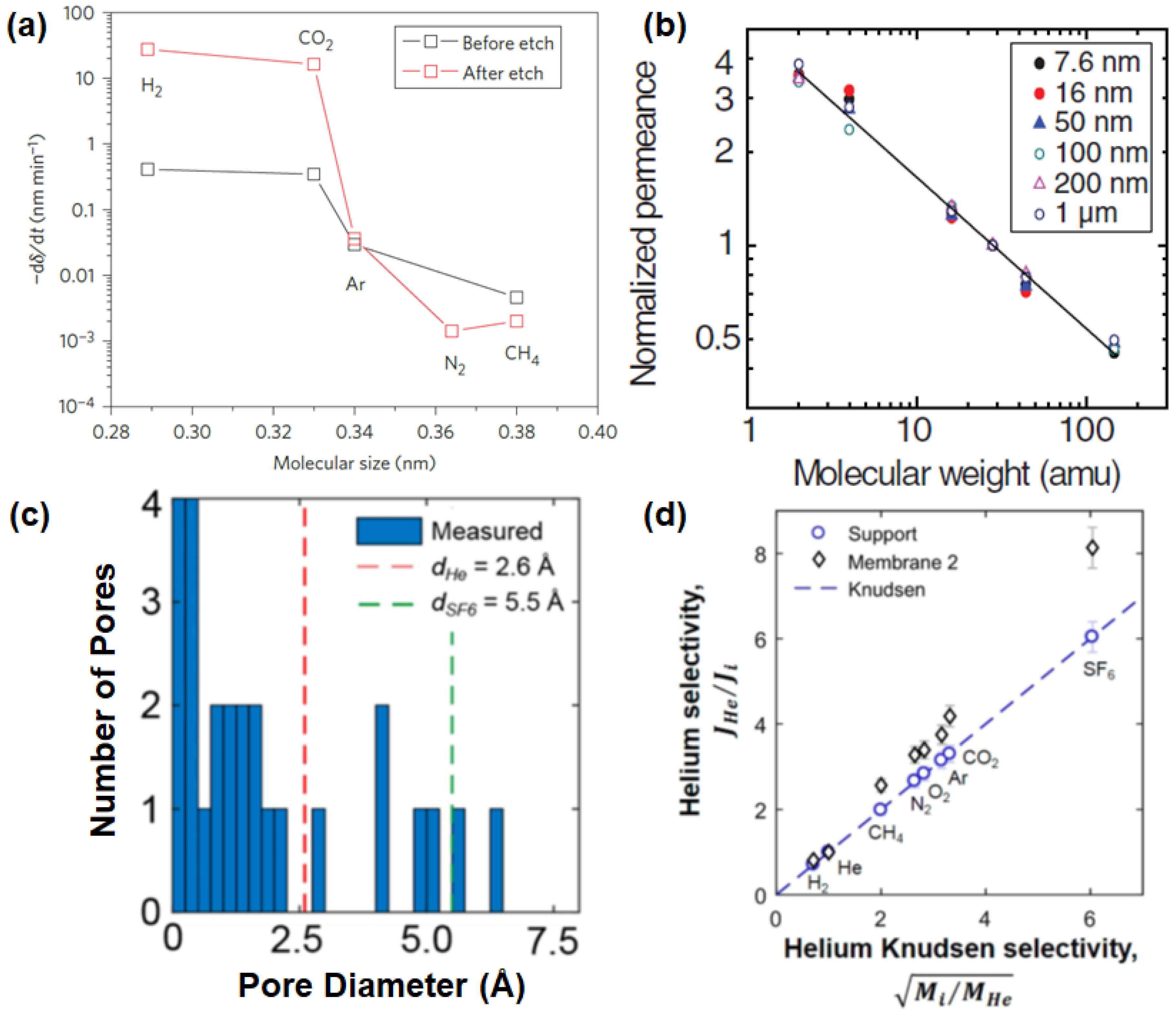
2.1. Single-Layer Graphene
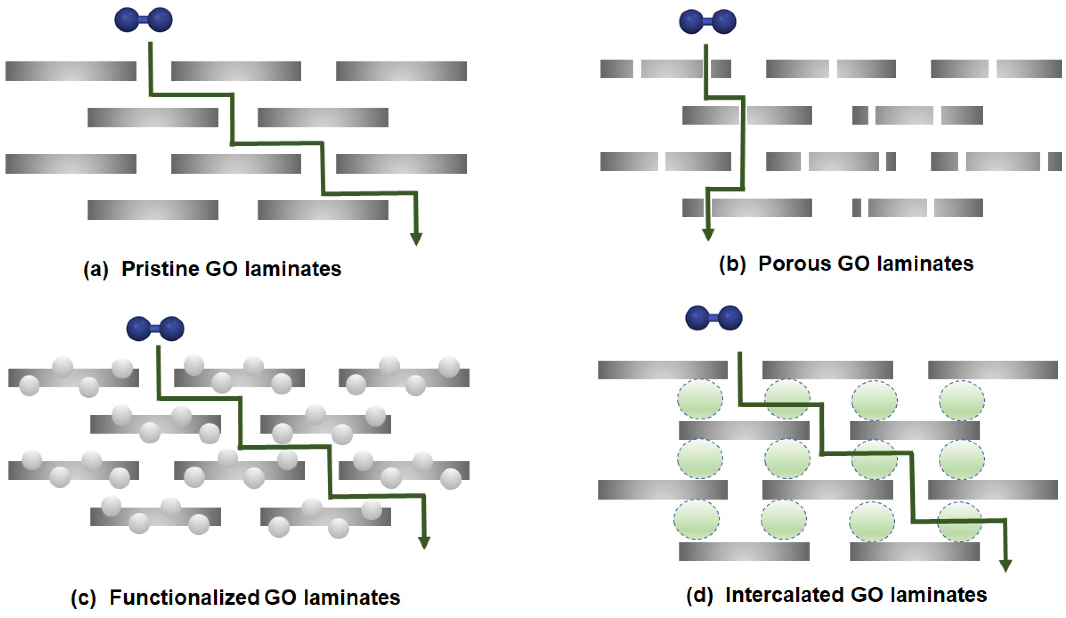
2.2. Multi-Layer Graphene
2.3. Graphene-Based Composites
3. Performance of a Graphene-Based Membrane
3.1. Investigation of the Membrane’s Performance in H2 Separation
3.1.1. Single-Layer Graphene
3.1.2. Multi-Layer Graphene
3.1.3. Graphene-Based Composites
3.2. Molecular Simulation and Modeling
3.2.1. Single-Layer Graphene
3.2.2. Multi-Layer Graphene
3.2.3. Graphene-Based Composites
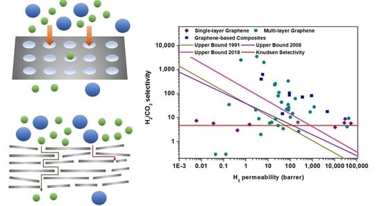
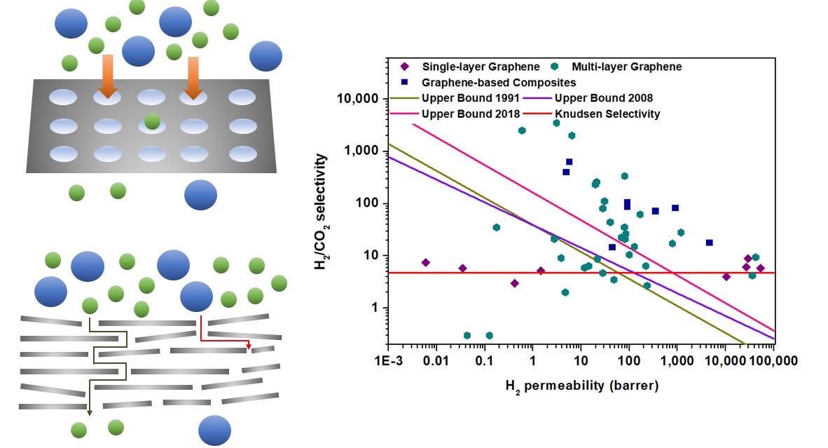
3.3. Comparison with Upper-Bound Limits
4. Conclusions and Future Perspective
Author Contributions
Funding
Conflicts of Interest
Nomenclature
| Symbol | Full Name |
| Al2O3 | Alumina (aluminum oxide) |
| BET | Brunauer-Emmett-Teller |
| COF | Covalent organic framework |
| Cu | Copper |
| CVD | Chemical vapor deposition |
| DFT | Density functional theory |
| EDA | Ethylenediamine |
| EFDA | External force driven assembly |
| FIB | Focused ion beam |
| FTIR | Fourier transform infrared spectroscopy |
| GO | Graphene oxide |
| GPU | Gas permeation unit |
| ISA | Integrally skin asymmetric |
| LDA | Local density approximation |
| MCE | Mixed cellulose ester |
| MD | Molecular dynamics |
| MMM | Mixed-matrix membrane |
| MOF | Metal-organic framework |
| MOP | Microporous organic polymer |
| NPC | Nanoporous carbon |
| NS | Nanosheet |
| ODPA | 4,4′-oxydiphthalic anhydride |
| PBE | Perdew, Burke and Erzenhoff |
| PES5 | Polyethersulfone |
| PETE | Polyester track etch |
| PI | Polyimide (Matrimid® 5218) |
| PMMA | Poly(methyl methacrylate) |
| PSA | Pressure swing adsorption |
| PSF | Polysulfone |
| rGO | Reduced graphene oxide |
| RT | Room temperature |
| SDBS | Sodium dodecylbenzenesulfonate |
| Sil-1-Al2O3 | Silicalite-1 modified alumina |
| SOD | Hydroxy sodalite |
| STEM | Scanning transmission electron microscopy |
| TMPDA | 2,4,6-trimethyl-m-phenylenediamine |
| vdW-DF | van der Waals density functional |
| YSZ | Yttrium-stabilized zirconia (ceramic) |
References
- Ahmadpour, J.; Ahmadi, M.; Javdani, A. Hydrodesulfurization unit for natural gas condensate. J. Therm. Anal. Calorim. 2019, 135, 1943–1949. [Google Scholar] [CrossRef]
- Kadijani, J.A.; Narimani, E. Simulation of hydrodesulfurization unit for natural gas condensate with high sulfur content. Appl. Petrochem. Res. 2016, 6, 25–34. [Google Scholar] [CrossRef] [Green Version]
- Frauzem, R.; Kongpanna, P.; Roh, K.; Lee, J.H.; Pavarajarn, V.; Assabumrungrat, S.; Gani, R. Chapter 7—Sustainable Process Design: Sustainable Process Networks for Carbon Dioxide Conversion. In Computer Aided Chemical Engineering; You, F., Ed.; Elsevier: Amsterdam, The Netherlands, 2015; Volume 36, pp. 175–195. [Google Scholar]
- Germeshuizen, L.M.; Blom, P. A techno-economic evaluation of the use of hydrogen in a steel production process, utilizing nuclear process heat. Int. J. Hydrog. Energy 2013, 38, 10671–10682. [Google Scholar] [CrossRef]
- Grundt, T.; Christiansen, K. Hydrogen by water electrolysis as basis for small scale ammonia production. A comparison with hydrocarbon based technologies. Int. J. Hydrog. Energy 1982, 7, 247–257. [Google Scholar] [CrossRef]
- Yang, E.; Alayande, A.B.; Goh, K.; Kim, C.-M.; Chu, K.-H.; Hwang, M.-H.; Ahn, J.-H.; Chae, K.-J. 2D materials-based membranes for hydrogen purification: Current status and future prospects. Int. J. Hydrog. Energy 2020. [Google Scholar] [CrossRef]
- Chuah, C.Y.; Goh, K.; Yang, Y.; Gong, H.; Li, W.; Karahan, H.E.; Guiver, M.D.; Wang, R.; Bae, T.-H. Harnessing filler materials for enhancing biogas separation membranes. Chem. Rev. 2018, 118, 8655–8769. [Google Scholar] [CrossRef]
- Chuah, C.Y.; Kim, K.; Lee, J.; Koh, D.-Y.; Bae, T.-H. CO2 absorption using membrane contactors: Recent progress and future perspective. Ind. Eng. Chem. Res. 2019, 59, 6773–6794. [Google Scholar] [CrossRef]
- IEA. The Future of Hydrogen. Available online: https://www.iea.org/reports/the-future-of-hydrogen (accessed on 6 June 2020).
- OFFICE of ENERGY EFFICIENCY and RENEWABLE ENERGY. Hydrogen Production: Natural Gas Reforming. Available online: https://www.energy.gov/eere/fuelcells/hydrogen-production-natural-gas-reforming (accessed on 6 June 2020).
- Vozniuk, O.; Tanchoux, N.; Millet, J.-M.; Albonetti, S.; Di Renzo, F.; Cavani, F. Chapter 14—Spinel Mixed Oxides for Chemical-Loop Reforming: From Solid State to Potential Application. In Studies in Surface Science and Catalysis; Albonetti, S., Perathoner, S., Quadrelli, E.A., Eds.; Elsevier: Amsterdam, The Netherlands, 2019; Volume 178, pp. 281–302. [Google Scholar]
- Navarro Yerga, R.M.; Alvarez-Galván, M.C.; Vaquero, F.; Arenales, J.; Fierro, J.L.G. Chapter 3—Hydrogen Production from Water Splitting Using Photo-Semiconductor Catalysts. In Renewable Hydrogen Technologies; Gandía, L.M., Arzamendi, G., Diéguez, P.M., Eds.; Elsevier: Amsterdam, The Netherlands, 2013; pp. 43–61. [Google Scholar]
- Chuah, C.Y.; Goh, K.; Bae, T.-H. Hierarchically structured HKUST-1 nanocrystals for enhanced SF6 capture and recovery. J. Phys. Chem. C 2017, 121, 6748–6755. [Google Scholar] [CrossRef]
- Chuah, C.Y.; Yu, S.; Na, K.; Bae, T.-H. Enhanced SF6 recovery by hierarchically structured MFI zeolite. J. Ind. Eng. Chem. 2018, 62, 64–71. [Google Scholar] [CrossRef]
- Chuah, C.Y.; Yang, Y.; Bae, T.-H. Hierarchically porous polymers containing triphenylamine for enhanced SF6 separation. Micropor. Mesopor. Mater. 2018, 272, 232–240. [Google Scholar] [CrossRef]
- Yang, Y.; Goh, K.; Chuah, C.Y.; Karahan, H.E.; Birer, Ö.; Bae, T.-H. Sub-Ångström-level engineering of ultramicroporous carbons for enhanced sulfur hexafluoride capture. Carbon 2019, 155, 56–64. [Google Scholar] [CrossRef]
- Tao, W.; Ma, S.; Xiao, J.; Bénard, P.; Chahine, R. Simulation and optimization for hydrogen purification performance of vacuum pressure swing adsorption. Energy Procedia 2019, 158, 1917–1923. [Google Scholar] [CrossRef]
- Xu, G.; Liang, F.; Yang, Y.; Hu, Y.; Zhang, K.; Liu, W. An Improved CO2 Separation and Purification System Based on Cryogenic Separation and Distillation Theory. Energies 2014, 7, 3484–3502. [Google Scholar] [CrossRef] [Green Version]
- Wongchitphimon, S.; Lee, S.S.; Chuah, C.Y.; Wang, R.; Bae, T.H. Composite Materials for Carbon Capture; John Wiley & Sons: Hoboken, NJ, USA, 2020; pp. 237–266. [Google Scholar]
- Zhang, X.; Chuah, C.Y.; Dong, P.; Cha, Y.-H.; Bae, T.-H.; Song, M.-K. Hierarchically porous Co-MOF-74 hollow nanorods for enhanced dynamic CO2 separation. ACS Appl. Mater. Interfaces 2018, 10, 43316–43322. [Google Scholar] [CrossRef] [PubMed]
- Lee, J.; Chuah, C.Y.; Kim, J.; Kim, Y.; Ko, N.; Seo, Y.; Kim, K.; Bae, T.H.; Lee, E. Separation of Acetylene from Carbon Dioxide and Ethylene by a Water-Stable Microporous Metal–Organic Framework with Aligned Imidazolium Groups inside the Channels. Angew. Chem. Int. Ed. 2018, 130, 7995–7999. [Google Scholar] [CrossRef]
- Samarasinghe, S.A.S.C.; Chuah, C.Y.; Li, W.; Sethunga, G.S.M.D.P.; Wang, R.; Bae, T.-H. Incorporation of CoIII acetylacetonate and SNW-1 nanoparticles to tailor O2/N2 separation performance of mixed-matrix membrane. Sep. Purif. Technol. 2019, 223, 133–141. [Google Scholar] [CrossRef]
- Chuah, C.Y.; Samarasinghe, S.A.S.C.; Li, W.; Goh, K.; Bae, T.-H. Leveraging Nanocrystal HKUST-1 in Mixed-Matrix Membranes for Ethylene/Ethane Separation. Membranes 2020, 10, 74. [Google Scholar] [CrossRef]
- Samarasinghe, S.A.S.C.; Chuah, C.Y.; Karahan, H.E.; Sethunga, G.S.M.D.P.; Bae, T.H. Enhanced O2/N2 Separation of Mixed-Matrix Membrane Filled with Pluronic-Compatibilized Cobalt Phthalocyanine Particles. Membranes 2020, 10, 75. [Google Scholar] [CrossRef] [Green Version]
- Hinchliffe, A.B.; Porter, K.E. A Comparison of Membrane Separation and Distillation. Chem. Eng. Res. Des. 2000, 78, 255–268. [Google Scholar] [CrossRef]
- Gong, H.; Chuah, C.Y.; Yang, Y.; Bae, T.-H. High performance composite membranes comprising Zn(pyrz)2(SiF6) nanocrystals for CO2/CH4 separation. J. Ind. Eng. Chem. 2018, 60, 279–285. [Google Scholar] [CrossRef]
- Wongchitphimon, S.; Rongwong, W.; Chuah, C.Y.; Wang, R.; Bae, T.-H. Polymer-fluorinated silica composite hollow fiber membranes for the recovery of biogas dissolved in anaerobic effluent. J. Membr. Sci. 2017, 540, 146–154. [Google Scholar] [CrossRef]
- Robeson, L.M. Correlation of separation factor versus permeability for polymeric membranes. J. Membr. Sci. 1991, 62, 165–185. [Google Scholar] [CrossRef]
- Robeson, L.M. The upper bound revisited. J. Membr. Sci. 2008, 320, 390–400. [Google Scholar] [CrossRef]
- Chuah, C.Y.; Bae, T.-H. Incorporation of Cu3BTC2 nanocrystals to increase the permeability of polymeric membranes in O2/N2 separation. BMC Chem. Eng. 2019, 1, 2. [Google Scholar] [CrossRef]
- Pandey, P.; Chauhan, R.S. Membranes for gas separation. Prog. Polym. Sci. 2001, 26, 853–893. [Google Scholar] [CrossRef]
- Chuah, C.Y.; Lee, J.; Song, J.; Bae, T.-H. CO2/N2 Separation Properties of Polyimide-Based Mixed-Matrix Membranes Comprising UiO-66 with Various Functionalities. Membranes 2020, 10, 154. [Google Scholar] [CrossRef]
- Pera-Titus, M. Porous Inorganic Membranes for CO2 Capture: Present and Prospects. Chem. Rev. 2014, 114, 1413–1492. [Google Scholar] [CrossRef]
- Li, W.; Goh, K.; Chuah, C.Y.; Bae, T.-H. Mixed-matrix carbon molecular sieve membranes using hierarchical zeolite: A simple approach towards high CO2 permeability enhancements. J. Membr. Sci. 2019, 588, 117220. [Google Scholar] [CrossRef]
- Ding, L.; Wei, Y.; Li, L.; Zhang, T.; Wang, H.; Xue, J.; Ding, L.-X.; Wang, S.; Caro, J.; Gogotsi, Y. MXene molecular sieving membranes for highly efficient gas separation. Nat. Commun. 2018, 9, 155. [Google Scholar] [CrossRef]
- Karahan, H.E.; Goh, K.; Zhang, C.; Yang, E.; Yıldırım, C.; Chuah, C.Y.; Ahunbay, M.G.; Lee, J.; Tantekin-Ersolmaz, Ş.B.; Chen, Y. MXene Materials for Designing Advanced Separation Membranes. Adv. Mater. 2020, 1906697. [Google Scholar] [CrossRef]
- Wang, D.; Wang, Z.; Wang, L.; Hu, L.; Jin, J. Ultrathin membranes of single-layered MoS2 nanosheets for high-permeance hydrogen separation. Nanoscale 2015, 7, 17649–17652. [Google Scholar] [CrossRef]
- Liu, Y.; Wang, N.; Caro, J. In situ formation of LDH membranes of different microstructures with molecular sieve gas selectivity. J. Mater. Chem. A 2014, 2, 5716–5723. [Google Scholar] [CrossRef] [Green Version]
- Peng, Y.; Li, Y.; Ban, Y.; Jin, H.; Jiao, W.; Liu, X.; Yang, W. Metal-organic framework nanosheets as building blocks for molecular sieving membranes. Science 2014, 346, 1356. [Google Scholar] [CrossRef] [PubMed]
- Fan, H.; Mundstock, A.; Feldhoff, A.; Knebel, A.; Gu, J.; Meng, H.; Caro, J. Covalent Organic Framework–Covalent Organic Framework Bilayer Membranes for Highly Selective Gas Separation. J. Am. Chem. Soc. 2018, 140, 10094–10098. [Google Scholar] [CrossRef] [PubMed]
- Chuah, C.Y.; Nie, L.; Lee, J.-M.; Bae, T.-H. The influence of cations intercalated in graphene-oxide membranes in tuning H2/CO2 separation performance. Sep. Purif. Technol. 2020, 116933. [Google Scholar] [CrossRef]
- Zhang, Y.; Shi, Q.; Liu, Y.; Wang, Y.; Meng, Z.; Xiao, C.; Deng, K.; Rao, D.; Lu, R. Hexagonal Boron Nitride with Designed Nanopores as a High-Efficiency Membrane for Separating Gaseous Hydrogen from Methane. J. Phys. Chem. C 2015, 119, 19826–19831. [Google Scholar] [CrossRef]
- Huang, K.; Liu, G.; Lou, Y.; Dong, Z.; Shen, J.; Jin, W. A Graphene Oxide Membrane with Highly Selective Molecular Separation of Aqueous Organic Solution. Angew. Chem. Int. Ed. 2014, 53, 6929–6932. [Google Scholar] [CrossRef] [PubMed]
- Hu, Y.; Dong, X.; Nan, J.; Jin, W.; Ren, X.; Xu, N.; Lee, Y.M. Metal–organic framework membranes fabricated via reactive seeding. Chem. Commun. 2011, 47, 737–739. [Google Scholar] [CrossRef]
- Li, W.; Su, P.; Li, Z.; Xu, Z.; Wang, F.; Ou, H.; Zhang, J.; Zhang, G.; Zeng, E. Ultrathin metal–organic framework membrane production by gel–vapour deposition. Nat. Commun. 2017, 8, 406. [Google Scholar] [CrossRef]
- Nie, L.; Chuah, C.Y.; Bae, T.H.; Lee, J.M. Graphene-Based Advanced Membrane Applications in Organic Solvent Nanofiltration. Adv. Func. Mater. 2020, 2006949. [Google Scholar] [CrossRef]
- Li, W.; Chuah, C.Y.; Nie, L.; Bae, T.-H. Enhanced CO2/CH4 selectivity and mechanical strength of mixed-matrix membrane incorporated with NiDOBDC/GO composite. J. Ind. Eng. Chem. 2019, 74, 118–125. [Google Scholar] [CrossRef]
- Norahim, N.; Faungnawakij, K.; Quitain, A.T.; Klaysom, C. Composite membranes of graphene oxide for CO2/CH4 separation. J. Chem. Tech. Biotechnol. 2019, 94, 2783–2791. [Google Scholar] [CrossRef]
- Ali, A.; Pothu, R.; Siyal, S.H.; Phulpoto, S.; Sajjad, M.; Thebo, K.H. Graphene-based membranes for CO2 separation. Mater. Sci. Energy Technol. 2019, 2, 83–88. [Google Scholar] [CrossRef]
- Alen, S.K.; Nam, S.; Dastgheib, S.A. Recent advances in graphene oxide membranes for gas separation applications. Int. J. Mol. Sci. 2019, 20, 5609. [Google Scholar] [CrossRef] [PubMed] [Green Version]
- Li, J.-R.; Kuppler, R.J.; Zhou, H.-C. Selective gas adsorption and separation in metal–organic frameworks. Chem. Soc. Rev. 2009, 38, 1477–1504. [Google Scholar] [CrossRef]
- Chuah, C.Y. Microporous Materials with Tailored Structural Properties for Enhanced Gas Separation; Nanyang Technological University: Singapore, 2019. [Google Scholar]
- Liu, G.; Jin, W.; Xu, N. Graphene-based membranes. Chem. Soc. Rev. 2015, 44, 5016–5030. [Google Scholar] [CrossRef]
- Goh, K.; Karahan, H.E.; Yang, E.; Bae, T.-H. Graphene-Based membranes for CO2/CH4 separation: Key challenges and perspectives. Appl. Sci. 2019, 9, 2784. [Google Scholar] [CrossRef] [Green Version]
- Goh, K.; Karahan, H.E.; Wei, L.; Bae, T.-H.; Fane, A.G.; Wang, R.; Chen, Y. Carbon nanomaterials for advancing separation membranes: A strategic perspective. Carbon 2016, 109, 694–710. [Google Scholar] [CrossRef]
- Bunch, J.S.; Verbridge, S.S.; Alden, J.S.; Van Der Zande, A.M.; Parpia, J.M.; Craighead, H.G.; McEuen, P.L. Impermeable atomic membranes from graphene sheets. Nano Lett. 2008, 8, 2458–2462. [Google Scholar] [CrossRef] [Green Version]
- Yoo, B.M.; Shin, H.J.; Yoon, H.W.; Park, H.B. Graphene and graphene oxide and their uses in barrier polymers. J. Appl. Polym. Sci. 2014, 131. [Google Scholar] [CrossRef]
- Berry, V. Impermeability of graphene and its applications. Carbon 2013, 62, 1–10. [Google Scholar] [CrossRef]
- Leenaerts, O.; Partoens, B.; Peeters, F. Graphene: A perfect nanoballoon. Appl. Phys. Lett. 2008, 93, 193107. [Google Scholar] [CrossRef] [Green Version]
- Wilkes, J.O.; Birmingham, S.G. Fluid Mechanics for Chemical Engineers with Microfluidics and CFD, 2nd ed.; Pearson Education: Upper Saddle River, NJ, USA, 2006. [Google Scholar]
- Nielsen, L.E. Models for the permeability of filled polymer systems. J. Macromol. Sci. Chem. 1967, 1, 929–942. [Google Scholar] [CrossRef]
- Yang, E.; Goh, K.; Chuah, C.Y.; Wang, R.; Bae, T.-H. Asymmetric mixed-matrix membranes incorporated with nitrogen-doped graphene nanosheets for highly selective gas separation. J. Membr. Sci. 2020, 118293. [Google Scholar] [CrossRef]
- Yang, E.; Karahan, H.E.; Goh, K.; Chuah, C.Y.; Wang, R.; Bae, T.-H. Scalable fabrication of graphene-based laminate membranes for liquid and gas separations by crosslinking-induced gelation and doctor-blade casting. Carbon 2019, 155, 129–137. [Google Scholar] [CrossRef]
- Li, W.; Chuah, C.Y.; Yang, Y.; Bae, T.-H. Nanocomposites formed by in situ growth of NiDOBDC nanoparticles on graphene oxide sheets for enhanced CO2 and H2 storage. Micropor. Mesopor. Mater. 2018, 265, 35–42. [Google Scholar] [CrossRef]
- Li, W.; Samarasinghe, S.A.S.C.; Bae, T.-H. Enhancing CO2/CH4 separation performance and mechanical strength of mixed-matrix membrane via combined use of graphene oxide and ZIF-8. J. Ind. Eng. Chem. 2018, 67, 156–163. [Google Scholar] [CrossRef]
- Brunauer, S.; Emmett, P.H.; Teller, E. Adsorption of Gases in Multimolecular Layers. J. Am. Chem. Soc. 1938, 60, 309–319. [Google Scholar] [CrossRef]
- Kumar, R.; Jayaramulu, K.; Maji, T.K.; Rao, C. Hybrid nanocomposites of ZIF-8 with graphene oxide exhibiting tunable morphology, significant CO2 uptake and other novel properties. Chem. Commun. 2013, 49, 4947–4949. [Google Scholar] [CrossRef]
- Liu, S.; Sun, L.; Xu, F.; Zhang, J.; Jiao, C.; Li, F.; Li, Z.; Wang, S.; Wang, Z.; Jiang, X. Nanosized Cu-MOFs induced by graphene oxide and enhanced gas storage capacity. Energy Environ. Sci. 2013, 6, 818–823. [Google Scholar] [CrossRef]
- Petit, C.; Bandosz, T.J. MOF–graphite oxide composites: Combining the uniqueness of graphene layers and metal–organic frameworks. Adv. Mater. 2009, 21, 4753–4757. [Google Scholar] [CrossRef]
- Huang, W.; Zhou, X.; Xia, Q.; Peng, J.; Wang, H.; Li, Z. Preparation and adsorption performance of GrO@ Cu-BTC for separation of CO2/CH4. Ind. Eng. Chem. Res. 2014, 53, 11176–11184. [Google Scholar] [CrossRef]
- Petit, C.; Burress, J.; Bandosz, T.J. The synthesis and characterization of copper-based metal–organic framework/graphite oxide composites. Carbon 2011, 49, 563–572. [Google Scholar] [CrossRef]
- Li, Y.; Miao, J.; Sun, X.; Xiao, J.; Li, Y.; Wang, H.; Xia, Q.; Li, Z. Mechanochemical synthesis of Cu-BTC@ GO with enhanced water stability and toluene adsorption capacity. Chem. Eng. J. 2016, 298, 191–197. [Google Scholar] [CrossRef]
- Petit, C.; Bandosz, T.J. Synthesis, characterization, and ammonia adsorption properties of mesoporous metal–organic framework (MIL (Fe))–graphite oxide composites: Exploring the limits of materials fabrication. Adv. Func. Mater. 2011, 21, 2108–2117. [Google Scholar] [CrossRef]
- Jahan, M.; Bao, Q.; Yang, J.-X.; Loh, K.P. Structure-directing role of graphene in the synthesis of metal− organic framework nanowire. J. Am. Chem. Soc. 2010, 132, 14487–14495. [Google Scholar] [CrossRef]
- Chen, Y.; Lv, D.; Wu, J.; Xiao, J.; Xi, H.; Xia, Q.; Li, Z. A new MOF-505@ GO composite with high selectivity for CO2/CH4 and CO2/N2 separation. Chem. Eng. J. 2017, 308, 1065–1072. [Google Scholar] [CrossRef]
- Andrea, D.; Szilvia, K.; János, M.; György, S.; Ying, W.; Krisztina, L. Graphene Oxide Protected Copper Benzene-1,3,5-Tricarboxylate for Clean Energy Gas Adsorption. Nanomaterials 2020, 10, 1182. [Google Scholar]
- Kim, H.W.; Yoon, H.W.; Yoon, S.-M.; Yoo, B.M.; Ahn, B.K.; Cho, Y.H.; Shin, H.J.; Yang, H.; Paik, U.; Kwon, S. Selective gas transport through few-layered graphene and graphene oxide membranes. Science 2013, 342, 91–95. [Google Scholar] [CrossRef] [Green Version]
- Li, H.; Song, Z.; Zhang, X.; Huang, Y.; Li, S.; Mao, Y.; Ploehn, H.J.; Bao, Y.; Yu, M. Ultrathin, molecular-sieving graphene oxide membranes for selective hydrogen separation. Science 2013, 342, 95–98. [Google Scholar] [CrossRef]
- Celebi, K.; Buchheim, J.; Wyss, R.M.; Droudian, A.; Gasser, P.; Shorubalko, I.; Kye, J.-I.; Lee, C.; Park, H.G. Ultimate Permeation Across Atomically Thin Porous Graphene. Science 2014, 344, 289. [Google Scholar] [CrossRef]
- Huang, A.; Liu, Q.; Wang, N.; Zhu, Y.; Caro, J.r. Bicontinuous zeolitic imidazolate framework ZIF-8@ GO membrane with enhanced hydrogen selectivity. J. Am. Chem. Soc. 2014, 136, 14686–14689. [Google Scholar] [CrossRef] [PubMed]
- Romanos, G.; Pastrana-Martínez, L.; Tsoufis, T.; Athanasekou, C.; Galata, E.; Katsaros, F.; Favvas, E.; Beltsios, K.; Siranidi, E.; Falaras, P. A facile approach for the development of fine-tuned self-standing graphene oxide membranes and their gas and vapor separation performance. J. Membr. Sci. 2015, 493, 734–747. [Google Scholar] [CrossRef]
- Wang, X.; Chi, C.; Tao, J.; Peng, Y.; Ying, S.; Qian, Y.; Dong, J.; Hu, Z.; Gu, Y.; Zhao, D. Improving the hydrogen selectivity of graphene oxide membranes by reducing non-selective pores with intergrown ZIF-8 crystals. Chem. Commun. 2016, 52, 8087–8090. [Google Scholar] [CrossRef] [PubMed]
- Chi, C.; Wang, X.; Peng, Y.; Qian, Y.; Hu, Z.; Dong, J.; Zhao, D. Facile preparation of graphene oxide membranes for gas separation. Chem. Mater. 2016, 28, 2921–2927. [Google Scholar] [CrossRef]
- Shen, J.; Liu, G.; Huang, K.; Chu, Z.; Jin, W.; Xu, N. Subnanometer two-dimensional graphene oxide channels for ultrafast gas sieving. ACS Nano 2016, 10, 3398–3409. [Google Scholar] [CrossRef]
- Guan, K.; Shen, J.; Liu, G.; Zhao, J.; Zhou, H.; Jin, W. Spray-evaporation assembled graphene oxide membranes for selective hydrogen transport. Sep. Purif. Technol. 2017, 174, 126–135. [Google Scholar] [CrossRef]
- Zhu, J.; Meng, X.; Zhao, J.; Jin, Y.; Yang, N.; Zhang, S.; Sunarso, J.; Liu, S. Facile hydrogen/nitrogen separation through graphene oxide membranes supported on YSZ ceramic hollow fibers. J. Membr. Sci. 2017, 535, 143–150. [Google Scholar] [CrossRef]
- Jia, M.; Feng, Y.; Liu, S.; Qiu, J.; Yao, J. Graphene oxide gas separation membranes intercalated by UiO-66-NH2 with enhanced hydrogen separation performance. J. Membr. Sci. 2017, 539, 172–177. [Google Scholar] [CrossRef]
- Huang, K.; Yuan, J.; Shen, G.; Liu, G.; Jin, W. Graphene oxide membranes supported on the ceramic hollow fibre for efficient H2 recovery. Chin. J. Chem. Eng. 2017, 25, 752–759. [Google Scholar] [CrossRef]
- Boutilier, M.S.H.; Jang, D.; Idrobo, J.-C.; Kidambi, P.R.; Hadjiconstantinou, N.G.; Karnik, R. Molecular Sieving Across Centimeter-Scale Single-Layer Nanoporous Graphene Membranes. ACS Nano 2017, 11, 5726–5736. [Google Scholar] [CrossRef] [PubMed]
- Lin, H.; Liu, R.; Dangwal, S.; Kim, S.-J.; Mehra, N.; Li, Y.; Zhu, J. Permselective H2/CO2 separation and desalination of hybrid GO/rGO membranes with controlled pre-cross-linking. ACS Appl. Mater. Interfaces 2018, 10, 28166–28175. [Google Scholar] [CrossRef] [PubMed]
- Zeynali, R.; Ghasemzadeh, K.; Sarand, A.B.; Kheiri, F.; Basile, A. Performance evaluation of graphene oxide (GO) nanocomposite membrane for hydrogen separation: Effect of dip coating sol concentration. Sep. Purif. Technol. 2018, 200, 169–176. [Google Scholar] [CrossRef]
- Kang, Z.; Wang, S.; Fan, L.; Zhang, M.; Kang, W.; Pang, J.; Du, X.; Guo, H.; Wang, R.; Sun, D. In situ generation of intercalated membranes for efficient gas separation. Commun. Chem. 2018, 1, 3. [Google Scholar] [CrossRef] [Green Version]
- Li, Y.; Liu, H.; Wang, H.; Qiu, J.; Zhang, X. GO-guided direct growth of highly oriented metal–organic framework nanosheet membranes for H2/CO2 separation. Chem. Sci. 2018, 9, 4132–4141. [Google Scholar] [CrossRef] [Green Version]
- Ibrahim, A.F.; Lin, Y. Synthesis of graphene oxide membranes on polyester substrate by spray coating for gas separation. Chem. Eng. Sci. 2018, 190, 312–319. [Google Scholar] [CrossRef]
- Ibrahim, A.; Lin, Y. Gas permeation and separation properties of large-sheet stacked graphene oxide membranes. J. Membr. Sci. 2018, 550, 238–245. [Google Scholar] [CrossRef]
- Huang, S.; Dakhchoune, M.; Luo, W.; Oveisi, E.; He, G.; Rezaei, M.; Zhao, J.; Alexander, D.T.L.; Züttel, A.; Strano, M.S.; et al. Single-layer graphene membranes by crack-free transfer for gas mixture separation. Nat. Commun. 2018, 9, 2632. [Google Scholar] [CrossRef]
- Ma, S.; Tang, Z.; Fan, Y.; Zhao, J.; Meng, X.; Yang, N.; Zhuo, S.; Liu, S. Surfactant-modified graphene oxide membranes with tunable structure for gas separation. Carbon 2019, 152, 144–150. [Google Scholar] [CrossRef]
- Ibrahim, A.F.; Banihashemi, F.; Lin, Y. Graphene oxide membranes with narrow inter-sheet galleries for enhanced hydrogen separation. Chem. Commun. 2019, 55, 3077–3080. [Google Scholar] [CrossRef]
- Meng, X.; Fan, Y.; Zhu, J.; Jin, Y.; Li, C.; Yang, N.; Zhao, J.; Sunarso, J.; Liu, S. Improving hydrogen permeation and interface property of ceramic-supported graphene oxide membrane via embedding of silicalite-1 zeolite into Al2O3 hollow fiber. Sep. Purif. Technol. 2019, 227, 115712. [Google Scholar] [CrossRef]
- Zhao, J.; He, G.; Huang, S.; Villalobos, L.F.; Dakhchoune, M.; Bassas, H.; Agrawal, K.V. Etching gas-sieving nanopores in single-layer graphene with an angstrom precision for high-performance gas mixture separation. Sci. Adv. 2019, 5, eaav1851. [Google Scholar] [CrossRef] [PubMed] [Green Version]
- Shimizu, K.; Ohba, T. Extremely permeable porous graphene with high H2/CO2 separation ability achieved by graphene surface rejection. Phys. Chem. Chem. Phys. 2017, 19, 18201–18207. [Google Scholar] [CrossRef] [PubMed]
- Lee, S.E.; Jang, J.; Kim, J.; Woo, J.Y.; Seo, S.; Jo, S.; Kim, J.-W.; Jeon, E.-S.; Jung, Y.; Han, C.-S. Tunable sieving of small gas molecules using horizontal graphene oxide membrane. J. Membr. Sci. 2020, 118178. [Google Scholar] [CrossRef]
- Cheng, L.; Guan, K.; Liu, G.; Jin, W. Cysteamine-crosslinked graphene oxide membrane with enhanced hydrogen separation property. J. Membr. Sci. 2020, 595, 117568. [Google Scholar] [CrossRef]
- Guo, H.; Kong, G.; Yang, G.; Pang, J.; Kang, Z.; Feng, S.; Zhao, L.; Fan, L.; Zhu, L.; Vicente, A. Cross-Linking between Sodalite Nanoparticles and Graphene Oxide in Composite Membranes to Trigger High Gas Permeance, Selectivity, and Stability in Hydrogen Separation. Angew. Chem. Int. Ed. 2020, 59, 6284–6288. [Google Scholar] [CrossRef]
- Castarlenas, S.; Téllez, C.; Coronas, J. Gas separation with mixed matrix membranes obtained from MOF UiO-66-graphite oxide hybrids. J. Membr. Sci. 2017, 526, 205–211. [Google Scholar] [CrossRef] [Green Version]
- Khan, M.H.; Moradi, M.; Dakhchoune, M.; Rezaei, M.; Huang, S.; Zhao, J.; Agrawal, K.V. Hydrogen sieving from intrinsic defects of benzene-derived single-layer graphene. Carbon 2019, 153, 458–466. [Google Scholar] [CrossRef]
- Rezaei, M.; Li, S.; Huang, S.; Agrawal, K.V. Hydrogen-sieving single-layer graphene membranes obtained by crystallographic and morphological optimization of catalytic copper foil. J. Membr. Sci. 2020, 612, 118406. [Google Scholar] [CrossRef]
- Koenig, S.P.; Wang, L.; Pellegrino, J.; Bunch, J.S. Selective molecular sieving through porous graphene. Nat. Nanotechnol. 2012, 7, 728–732. [Google Scholar] [CrossRef] [Green Version]
- Stankovich, S.; Piner, R.D.; Chen, X.; Wu, N.; Nguyen, S.T.; Ruoff, R.S. Stable aqueous dispersions of graphitic nanoplatelets via the reduction of exfoliated graphite oxide in the presence of poly (sodium 4-styrenesulfonate). J. Mater. Chem. 2006, 16, 155–158. [Google Scholar] [CrossRef]
- Dikin, D.A.; Stankovich, S.; Zimney, E.J.; Piner, R.D.; Dommett, G.H.; Evmenenko, G.; Nguyen, S.T.; Ruoff, R.S. Preparation and characterization of graphene oxide paper. Nature 2007, 448, 457–460. [Google Scholar] [CrossRef] [PubMed]
- Tsou, C.-H.; An, Q.-F.; Lo, S.-C.; De Guzman, M.; Hung, W.-S.; Hu, C.-C.; Lee, K.-R.; Lai, J.-Y. Effect of microstructure of graphene oxide fabricated through different self-assembly techniques on 1-butanol dehydration. J. Membr. Sci. 2015, 477, 93–100. [Google Scholar] [CrossRef]
- Chen, L.; Shi, G.; Shen, J.; Peng, B.; Zhang, B.; Wang, Y.; Bian, F.; Wang, J.; Li, D.; Qian, Z. Ion sieving in graphene oxide membranes via cationic control of interlayer spacing. Nature 2017, 550, 380–383. [Google Scholar] [CrossRef] [PubMed]
- Stankovich, S.; Dikin, D.A.; Compton, O.C.; Dommett, G.H.; Ruoff, R.S.; Nguyen, S.T. Systematic post-assembly modification of graphene oxide paper with primary alkylamines. Chem. Mater. 2010, 22, 4153–4157. [Google Scholar] [CrossRef]
- Gao, Y.; Liu, L.-Q.; Zu, S.-Z.; Peng, K.; Zhou, D.; Han, B.-H.; Zhang, Z. The effect of interlayer adhesion on the mechanical behaviors of macroscopic graphene oxide papers. ACS Nano 2011, 5, 2134–2141. [Google Scholar] [CrossRef]
- Hummers Jr, W.S.; Offeman, R.E. Preparation of graphitic oxide. J. Am. Chem. Soc. 1958, 80, 1339. [Google Scholar] [CrossRef]
- Brodie, B.C. XIII. On the atomic weight of graphite. Philosophical Transactions of the Royal Society of London 1859, 149, 249–259. [Google Scholar]
- Samarasinghe, S.; Chuah, C.Y.; Yang, Y.; Bae, T.-H. Tailoring CO2/CH4 separation properties of mixed-matrix membranes via combined use of two-and three-dimensional metal-organic frameworks. J. Membr. Sci. 2018, 557, 30–37. [Google Scholar] [CrossRef]
- Chuah, C.Y.; Li, W.; Samarasinghe, S.; Sethunga, G.; Bae, T.-H. Enhancing the CO2 separation performance of polymer membranes via the incorporation of amine-functionalized HKUST-1 nanocrystals. Micropor. Mesopor. Mater. 2019, 290, 109680. [Google Scholar] [CrossRef]
- Schrier, J. Helium separation using porous graphene membranes. J. Phys. Chem. Lett. 2010, 1, 2284–2287. [Google Scholar] [CrossRef]
- Jiang, D.-e.; Cooper, V.R.; Dai, S. Porous graphene as the ultimate membrane for gas separation. Nano Lett. 2009, 9, 4019–4024. [Google Scholar] [CrossRef] [PubMed]
- Du, H.; Li, J.; Zhang, J.; Su, G.; Li, X.; Zhao, Y. Separation of hydrogen and nitrogen gases with porous graphene membrane. J. Phys. Chem. C 2011, 115, 23261–23266. [Google Scholar] [CrossRef]
- Drahushuk, L.W.; Strano, M.S. Mechanisms of gas permeation through single layer graphene membranes. Langmuir 2012, 28, 16671–16678. [Google Scholar] [CrossRef] [PubMed]
- Tao, Y.; Xue, Q.; Liu, Z.; Shan, M.; Ling, C.; Wu, T.; Li, X. Tunable hydrogen separation in porous graphene membrane: First-principle and molecular dynamic simulation. ACS Appl. Mater. Interfaces 2014, 6, 8048–8058. [Google Scholar] [CrossRef] [PubMed]
- Zheng, H.; Zhu, L.; He, D.; Guo, T.; Li, X.; Chang, X.; Xue, Q. Two-dimensional graphene oxide membrane for H2/CH4 separation: Insights from molecular dynamics simulations. Int. J. Hydrog. Energy 2017, 42, 30653–30660. [Google Scholar] [CrossRef]
- Vinh-Thang, H.; Kaliaguine, S. Predictive models for mixed-matrix membrane performance: A review. Chem. Rev. 2013, 113, 4980–5028. [Google Scholar] [CrossRef] [PubMed]
- Cussler, E.L. Membranes containing selective flakes. J. Membr. Sci. 1990, 52, 275–288. [Google Scholar] [CrossRef]
- Lin, H.; Van Wagner, E.; Freeman, B.D.; Toy, L.G.; Gupta, R.P. Plasticization-enhanced hydrogen purification using polymeric membranes. Science 2006, 311, 639–642. [Google Scholar] [CrossRef]
- Lin, W.-H.; Chung, T.-S. Gas permeability, diffusivity, solubility, and aging characteristics of 6FDA-durene polyimide membranes. J. Membr. Sci. 2001, 186, 183–193. [Google Scholar] [CrossRef]
- Swaidan, R.; Ghanem, B.; Pinnau, I. Fine-Tuned Intrinsically Ultramicroporous Polymers Redefine the Permeability/Selectivity Upper Bounds of Membrane-Based Air and Hydrogen Separations. ACS Macro Lett. 2015, 4, 947–951. [Google Scholar] [CrossRef] [Green Version]
- Chuah, C.Y.; Li, W.; Yang, Y.; Bae, T.-H. Evaluation of porous adsorbents for CO2 capture under humid conditions: The importance of recyclability. Chem. Eng. J. Adv. 2020, 3, 100021. [Google Scholar] [CrossRef]


| Gas | Kinetic Diameter (Å) | Polarizability × 1025 (cm3) | Dipole Moment × 1018 (esu cm) (a) | Quadrupole Moment × 1026 (esu cm2) (b) | |
|---|---|---|---|---|---|
| Helium | He (c) | 2.55 | 2.05 | 0 | 0 |
| Water vapor | H2O (c) | 2.64 | 14.5 | 1.85 | - |
| Hydrogen | H2 | 2.83 | 8.04 | 0 | 0.662 |
| Carbon dioxide | CO2 | 3.30 | 29.1 | 0 | 4.30 |
| Nitrogen | N2 | 3.64 | 17.4 | 0 | 1.52 |
| Methane | CH4 | 3.80 | 25.9 | 0 | 0 |
| Composites (a) | Particle Size of MOF (nm) | SBET (m2/g) | % Increment in SBET (b) | Ref. |
|---|---|---|---|---|
| HKUST-1/1% rGO | - | 1677 | 21.3 | [70] |
| HKUST-1/16% GO | micron-sized | 1550 | 3.3 | [64] |
| HKUST-1/9% GO | 10–40 | 1532 | 17.4 | [68] |
| HKUST-1/9% GO | 50 | 1002 | 10.2 | [71] |
| HKUST-1/5% GO | - | 1362 | 14.7 | [72] |
| MIL-100/4% GO | - | 1464 | 3.6 | [73] |
| MOF-5/10% GO | 50 | 806 | 1.6 | [69] |
| MOF-5/5% B-GO | 220–260 | 810 | 1.1 | [74] |
| MOF-505/5% GO | micron-sized | 1279 | 16.2 | [75] |
| NiDOBDC/10% GO | 20–35 | 1190 | 26.6 | [76] |
| ZIF-8/1% GO | 100–150 | 819 | −26.9 | [67] |
| Membrane (a) | Measurement Conditions | H2 Permeance (GPU) | H2/CO2 Selectivity | Year (Ref.) | ||
|---|---|---|---|---|---|---|
| Selective Layer | Thickness (nm) | Support | ||||
| GO (spin-casting) | 5 | PES5 | - (pure gas, dry feed) | 25 | 0.2 | 13′ [77] |
| GO (spin-casting) | 5 | PES5 | - (pure gas, humidified feed) | 12 | 0.1 | 13′ [77] |
| GO (spin-coating) | 5 | PES5 | - (pure gas, dry feed) | 35 | 35 | 13′ [77] |
| GO (spin-coating) | 5 | PES5 | - (pure gas, humidified feed) | 8.5 | 0.3 | 13′ [77] |
| GO | 1.8 | Al2O3 | 20 °C, H2/CO2 (1:1) | 328 | 2500 | 13′ [78] |
| GO | 9 | Al2O3 | 20 °C, H2/CO2 (1:1) | 343 | 3500 | 13′ [78] |
| GO | 18 | Al2O3 | 20 °C, H2/CO2 (1:1) | 358 | 2000 | 13′ [78] |
| Graphene (1 layer) | 0.345 | PMMA | - (pure gas) | 2.99 × 10⁷ | 4 | 14′ [79] |
| GO (b) | - | Al2O3 | H2/CO2 (1:1) | 7 | 5.7 | 14′ [80] |
| ZIF-8@GO (b) | - | Al2O3 | H2/CO2 (1:1) | 44 | 5.2 | 14′ [80] |
| ZIF-8@GO | 100 | Al2O3 | 250 °C, 1 bar, H2/CO2 (1:1) | 433 | 14.9 | 14′ [80] |
| GO_M1_20 | 20,000 | MCE | - (pure gas) | 1.4 | 4.7 | 15′ [81] |
| GO_M3_20 | 20,000 | MCE | - (pure gas) | 2.4 | 3.5 | 15′ [81] |
| GO/ZIF-8 | 20 | α-Al2O3 | RT (pure gas) | 280 | 633 | 16′ [82] |
| GO/ZIF-8 | 20 | α-Al2O3 | RT, H2/CO2 (1:1) | 240 | 406 | 16′ [82] |
| GO (vacuum filtration) | - | Al2O3 | RT, H2/CO2 (1:1) | 1513 | 48 | 16′ [83] |
| GO (vacuum filtration) | - | Al2O3 | RT (pure gas) | 1746 | 58 | 16′ [83] |
| GO (spin-coating) | 20 | Al2O3 | RT, H2/CO2 (1:1) | 985 | 232 | 16′ [83] |
| GO (spin-coating) | 20 | Al2O3 | RT (pure gas) | 1045 | 259 | 16′ [83] |
| GO | 890 | Al2O3 | 2 bar, 25 °C (pure gas) | - | 5 | 16′ [84] |
| EFDA-GO | 890 | Al2O3 | 2 bar, 25 °C (pure gas) | 1326 | 28 | 16′ [84] |
| EFDA-GO | 890 | Al2O3 | -, H2/CO2 (1:1) | 876 | 17.2 | 16′ [84] |
| GO-0.5 | 1000 | Al2O3 | 1 bar, 25 °C (pure gas) | 81 | 20.9 | 17′ [85] |
| GO | 230 | YSZ | 20 °C (pure gas) | 133 | 111 | 17′ [86] |
| GO | 2340 | MCE | 25 °C (pure gas) | 2 | 2.0 | 17′ [87] |
| GOU (U: UiO-66-NH2) | 1900 | MCE | 25 °C (pure gas) | 116 | 6.4 | 17′ [87] |
| GO/U (U: UiO-66-NH2) | 4100 | MCE | 25 °C (pure gas) | 57 | 2.7 | 17′ [87] |
| GO (T-30) (c) | 320 | α-Al2O3 | RT (pure gas, dry feed) | 400 | 15.0 | 17′ [88] |
| GO (T-30) (c) | 320 | α-Al2O3 | RT (pure gas, humidified feed) | 313 | 10.5 | 17′ [88] |
| Graphene (1 layer) | 0.345 | AAO | - (pure gas) | 4179 | 5.16 | 17′ [89] |
| GO | - | α-Al2O3 | RT, H2/CO2 (1:1) | 127 | 17.3 | 18′ [90] |
| GO (b) | - | γ-Al2O3 | 3 bar, 20 °C (pure gas) | 1761 | 38.5 | 18′ [91] |
| GO | - | Nylon | - (pure gas) | 18,507 | 15 | 18′ [92] |
| CuO NS@GO-4 | 200 | Nylon | - (pure gas) | 22,687 | 18 | 18′ [92] |
| HKUST-1@GO-4 | 200 | Nylon | - (pure gas) | 4478 | 84 | 18′ [92] |
| HKUST-1@GO-4 | 200 | Nylon | -, H2/CO2 (1:1) | 1722 | 73.2 | 18′ [92] |
| GO-EDA-0 | - | α-Al2O3 | RT, H2/CO2 (1:1) | 339 | 11.6 | 18′ [90] |
| GO-EDA-1 | - | α-Al2O3 | RT, H2/CO2 (1:1) | 67 | 20.0 | 18′ [90] |
| GO-EDA-2 | - | α-Al2O3 | RT, H2/CO2 (1:1) | 73 | 22.9 | 18′ [90] |
| GO-Zn2(bim)4-ZnO | 200 | α-Al2O3 | 1 bar (pure gas) | 448 | 106 | 18′ [93] |
| GO-Zn2(bim)4-ZnO | 200 | α-Al2O3 | 1 bar. H2/CO2 (1:1) | 448 | 89 | 18′ [93] |
| MEM-F200 | 500 | PETE | RT (pure gas) | 159 | 35.3 | 18′ [94] |
| MEM-L1 | 200 | PETE | RT (pure gas) | 397 | 35.3 | 18′ [95] |
| MEM-L1 | 200 | PETE | RT, H2/CO2 (1:1) | 340 | 22.5 | 18′ [95] |
| MEM-S1 | - | PETE | RT (pure gas) | 546 | 24.7 | 18′ [95] |
| MEM-S1 | - | PETE | RT, H2/CO2 (1:1) | 475 | 16.6 | 18′ [95] |
| MEM-S250 | 500 | PETE | RT (pure gas) | 169 | 26.4 | 18′ [94] |
| Graphene (1 layer) (M8) | 0.345 | Macroporous support | 25 °C (pure gas) | 17 | 7.4 | 18′ [96] |
| Graphene (1 layer) (M2) | 0.345 | Macroporous support | 25 °C, H2/CO2 (1:1) | 100 | 5.8 | 18′ [96] |
| GO (b) | 300 | Al2O3 | RT (pure gas) | 134 | 44 | 19′ [97] |
| GO-SDBS (b) | 334 | Al2O3 | RT (pure gas) | 239 | 337 | 19′ [97] |
| GO-B (B: Brodie) | 200 | Polyester | RT (pure gas) | 141 | 80.7 | 19′ [98] |
| GO-H (H: Hummer) | 200 | Polyester | RT (pure gas) | 399 | 35.3 | 19′ [98] |
| GO (b) | 470 | Sil-1-Al2O3 | 1 bar, 25 °C (pure gas) | 358 | 62 | 19′ [99] |
| Graphene (1 layer) (M9) | 0.345 | Macroporous W support | 30 °C (pure gas) | 1200 | 3 | 19′ [100] |
| Graphene (1 layer) (M9) | 0.345 | Macroporous W support | 30 °C, H2/CO2 (1:1) | 1200 | 3 | 19′ [100] |
| Graphene (1 layer) | 0.345 | Stainless steel mesh | - (pure gas) | 1.55 × 10⁸ | 5.8 | 19′ [101] |
| Graphene (2 layer) | 0.69 | Stainless steel mesh | - (pure gas) | 3.88 × 10⁷ | 6.1 | 19′ [101] |
| Graphene (4 layer) | 1.38 | Stainless steel mesh | - (pure gas) | 2.09 × 10⁷ | 8.9 | 19′ [101] |
| GO | 20,000 | MCE | - (pure gas) | 1800 | 4.2 | 20′ [102] |
| rGO190 | 20,000 | MCE | - (pure gas) | 2100 | 9.4 | 20′ [102] |
| GO | 240 | Nylon | 1 bar, 25 °C (pure gas) | 49 | 5.9 | 20′ [41] |
| GO-Co2+ | 240 | Nylon | 1 bar, 25 °C (pure gas) | 60 | 6.4 | 20′ [41] |
| GO-La3+ | 240 | Nylon | 1 bar, 25 °C (pure gas) | 90 | 8.7 | 20′ [41] |
| GO-500 | 41 | Al2O3 | 1.5 bar, 25 °C (pure gas) | 94 | 9.1 | 20′ [103] |
| CGO-76 (C: Cysteamine) | 53 | Al2O3 | 1.5 bar, 25 °C (pure gas) | 52 | 21 | 20′ [103] |
| LCGO-40 (LC: L-cysteine) | - | Al2O3 | 1.5 bar, 25 °C (pure gas) | 42 | 12 | 20′ [103] |
| GO | - | Nylon | 1.2 bar, 25 °C, H2/CO2 (1:1) | 11,600 | 9 | 20′ [104] |
| SOD/GO-M1 | 900 | Nylon | 1.2 bar, 25 °C, H2/CO2 (1:1) | 1050 | 105 | 20′ [104] |
| Membrane (a) | Measurement Conditions | H2 Permeance (GPU) | H2/N2 Selectivity | Year (Ref.) | ||
|---|---|---|---|---|---|---|
| Skin Layer | Thickness (nm) | Support | ||||
| GO | 1.8 | Al2O3 | 20 °C, H2/N2 (1:1) | 328 | 220 | 13′ [78] |
| GO | 9 | Al2O3 | 20 °C, H2/N2 (1:1) | 343 | 300 | 13′ [78] |
| GO | 18 | Al2O3 | 20 °C, H2/N2 (1:1) | 358 | 1000 | 13′ [78] |
| GO (b) | - | Al2O3 | H2/CO2 (1:1) | 8 | 18.9 | 14′ [80] |
| ZIF-8@GO (b) | - | Al2O3 | H2/CO2 (1:1) | 46 | 10.7 | 14′ [80] |
| ZIF-8@GO | 100 | Al2O3 | 250 °C, 1 bar, H2/CO2 (1:1) | 433 | 90.5 | 14′ [80] |
| GO_M1_20 | 20,000 | MCE | - (pure gas) | 1.4 | 3.5 | 15′ [81] |
| GO_M3_20 | 20,000 | MCE | - (pure gas) | 2.4 | 6.9 | 15′ [81] |
| GO/ZIF-8 | 20 | α-Al2O3 | RT (pure gas) | 280 | 88 | 16′ [82] |
| GO/ZIF-8 | 20 | α-Al2O3 | RT, H2/CO2 (1:1) | 218 | 155 | 16′ [82] |
| GO (vacuum filtration) | - | Al2O3 | RT (pure gas) | 1746 | 65 | 16′ [83] |
| GO (spin coating) | 20 | Al2O3 | RT (pure gas) | 1045 | 292 | 16′ [83] |
| GO | 890 | Al2O3 | 0.2 MPa, 25 °C (pure gas) | - | 3.0 | 16′ [84] |
| EFDA-GO | 890 | Al2O3 | 0.2 MPa, 25 °C (pure gas) | 1123 | 7.5 | 16′ [84] |
| GO[c] | 230 | YSZ | 20 °C (pure gas) | 133 | 64 | 17′ [86] |
| GO | 2340 | MCE | 25 °C (pure gas) | 2 | 4.0 | 17′ [87] |
| GOU (U: UiO-66-NH2) | 1900 | MCE | 25 °C (pure gas) | 116 | 9.8 | 17′ [87] |
| GO/U (U: UiO-66-NH2) | 4100 | MCE | 25 °C (pure gas) | 57 | 7.0 | 17′ [87] |
| GO (T-30) (c) | 320 | α-Al2O3 | RT (pure gas, dry feed) | 400 | 7.2 | 17′ [88] |
| GO (T-30) (c) | 320 | α-Al2O3 | RT (pure gas, humidified feed) | 313 | 7.3 | 17′ [88] |
| GO | - | Nylon | - (pure gas) | 18,507 | 18 | 18′ [92] |
| CuO NS@GO-4 | 200 | Nylon | - (pure gas) | 22,687 | 21 | 18′ [92] |
| HKUST-1@GO-4 | 200 | Nylon | - (pure gas) | 4478 | 54 | 18′ [92] |
| GO (b) | - | γ-Al2O3 | 3 bar, 20 °C (pure gas) | 1761 | 16.5 | 18′ [91] |
| GO-Zn2(bim)4-ZnO | 200 | α-Al2O3 | 1 bar (pure gas) | 448 | 126 | 18′ [93] |
| GO-Zn2(bim)4-ZnO | 200 | α-Al2O3 | 1 bar. H2/N2 (1:1) | 448 | 103 | 18′ [93] |
| MEM-F200 | 500 | PETE | RT (pure gas) | 159 | 31.5 | 18′ [94] |
| MEM-L1 | 200 | PETE | RT (pure gas) | 397 | 29.6 | 18′ [95] |
| MEM-S1 | - | PETE | RT (pure gas) | 546 | 18.3 | 18′ [95] |
| MEM-S250 | 500 | PETE | RT (pure gas) | 169 | 23.7 | 18′ [94] |
| GO (b) | 300 | Al2O3 | RT (pure gas) | 134 | 36 | 19′ [97] |
| GO (b) | 470 | Sil-1-Al2O3 | 1 bar, 25 °C (pure gas) | 358 | 50 | 19′ [99] |
| GO (b) | 470 | Sil-1-Al2O3 | 1 bar, 20 °C, H2/N2 (1:1) | 328 | 40.7 | 19′ [99] |
| GO-SDBS (b) | 334 | Al2O3 | RT (pure gas) | 239 | 44 | 19′ [97] |
| GO-B | 200 | Polyester | RT (pure gas) | 141 | 60.1 | 19′ [98] |
| GO-H | 200 | Polyester | RT (pure gas) | 399 | 31.5 | 19′ [98] |
| Membrane (a) | Measurement Conditions | H2 Permeance (GPU) | H2/CH4 Selectivity | Year (Ref.) | ||
|---|---|---|---|---|---|---|
| Skin Layer | Thickness (nm) | Support | ||||
| GO (b) | - | Al2O3 | H2/CH4 (1:1) | 8 | 38.4 | 14′ [80] |
| ZIF-8@GO (b) | - | Al2O3 | H2/CH4 (1:1) | 44 | 12.8 | 14′ [80] |
| ZIF-8@GO | 100 | Al2O3 | 250 °C, 1 bar, H2/CH4 (1:1) | 433 | 139.1 | 14′ [80] |
| GO_M3_20 | 20,000 | MCE | - (pure gas) | 2.4 | 5.6 | 15′ [81] |
| GO/ZIF-8 | 20 | α-Al2O3 | RT (pure gas) | 280 | 162 | 16′ [82] |
| GO/ZIF-8 | 20 | α-Al2O3 | RT, H2/CH4 (1:1) | 218 | 355 | 16′ [82] |
| GO (vacuum filtration) | - | Al2O3 | RT (pure gas) | 1746 | 29.3 | 16′ [83] |
| GO (spin coating) | 20 | Al2O3 | RT (pure gas) | 1045 | 194 | 16′ [83] |
| GO (8 wt%)/PSF (c) | 50,000 | - | 35 °C (pure gas) | 0.1 | 28 | 17′ [105] |
| GO(30)_UiO-66_48h (8 wt%)/PSF (c) | 50,000 | - | 35 °C (pure gas) | 0.32 | 68 | 17′ [105] |
| GO (8 wt%)/PI (c) | 50,000 | - | 35 °C (pure gas) | 0.26 | 81 | 17′ [105] |
| GO(30)_UiO-66_48h (8 wt%)/PI (c) | 50,000 | - | 35 °C (pure gas) | 0.94 | 140 | 17′ [105] |
| GO | 230 | YSZ | 20 °C (pure gas) | 133 | 53 | 17′ [86] |
| GO (T-30) (d) | 320 | α-Al2O3 | RT (pure gas, dry feed) | 400 | 6.4 | 17′ [88] |
| GO (T-30) (d) | 320 | α-Al2O3 | RT (pure gas, humidified feed) | 313 | 6.5 | 17′ [88] |
| Graphene (1 layer) | 0.345 | AAO | - (pure gas) | 4179 | 3.17 | 17′ [89] |
| GO | - | Nylon | - (pure gas) | 18,507 | 3 | 18′ [92] |
| CuO NS@GO-4 | 200 | Nylon | - (pure gas) | 22,687 | 4 | 18′ [92] |
| HKUST-1@GO-4 | 200 | Nylon | - (pure gas) | 4478 | 35 | 18′ [92] |
| GO-Zn2(bim)4-ZnO | 200 | α-Al2O3 | 1 bar (pure gas) | 448 | 256 | 18′ [93] |
| GO-Zn2(bim)4-ZnO | 200 | α-Al2O3 | 1 bar. H2/CH4 (1:1) | 448 | 221 | 18′ [93] |
| MEM-L1 | 200 | PETE | RT (pure gas) | 397 | 16.6 | 18′ [95] |
| MEM-S1 | - | PETE | RT (pure gas) | 546 | 11.4 | 18′ [95] |
| MEM-F200 | 500 | PETE | RT (pure gas) | 159 | 15.7 | 18′ [94] |
| MEM-S250 | 500 | PETE | RT (pure gas) | 169 | 12.5 | 18′ [94] |
| Graphene (1 layer) (M5) | 0.345 | Macroporous support | 25 °C (pure gas) | 210 | 12.8 | 18′ [96] |
| Graphene (1 layer) (M2) | 0.345 | Macroporous support | 25 °C, H2/CH4 (1:1) | 100 | 11 | 18′ [96] |
| GO (c) | 300 | Al2O3 | RT (pure gas) | 134 | 14.5 | 19′ [97] |
| GO-SDBS | 334 | Al2O3 | RT (pure gas) | 239 | 20.5 | 19′ [97] |
| GO (c) | 470 | Sil-1-Al2O3 | 1 bar, 25 °C (pure gas) | 358 | 28 | 19′ [99] |
| GO-B | 200 | Polyester | RT (pure gas) | 141 | 27.7 | 19′ [98] |
| GO-H | 200 | Polyester | RT (pure gas) | 399 | 15.7 | 19′ [98] |
| Graphene (1 layer) (M4) | 0.345 | Macroporous W support | 30 °C (pure gas) | 1000 | 5.1 | 19′ [106] |
| Graphene (1 layer) (M9) | 0.345 | Macroporous W support | 30 °C (pure gas) | 1200 | 16 | 19′ [100] |
| Graphene (1 layer) (M9) | 0.345 | Macroporous W support | 30 °C, H2/CH4 (1:1) | 1200 | 16 | 19′ [100] |
| Graphene (1 layer) | 0.345 | Stainless steel mesh | - (pure gas) | 1.55 × 10⁸ | 2.5 | 19′ [101] |
| Graphene (2 layers) | 0.69 | Stainless steel mesh | - (pure gas) | 3.88 × 10⁷ | 2.3 | 19′ [101] |
| Graphene (4 layers) | 1.38 | Stainless steel mesh | - (pure gas) | 2.09 × 10⁷ | 3.0 | 19′ [101] |
| Graphene (1 layer) | 0.345 | Nanoporous carbon (NPC) | - (pure gas) | 1090 | 9.5 | 20′ [107] |
| Upper Bound Curve | Knudsen Selectivity | 1991 | 2008 | 2015 (2018) (b) | |||
|---|---|---|---|---|---|---|---|
| k (barrer) | n | k (barrer) | n | k (barrer) | n | ||
| H2/CO2 | 4.69 | 1200 | −1.94 | 4515 | −2.30 | 15,248 (c) | −1.89 (c) |
| H2/N2 | 3.74 | 52,918 | −1.53 | 97,650 | −1.48 | 1,100,000 | −1.46 |
| H2/CH4 | 2.83 | 18,500 | −1.21 | 27,200 | −1.11 | 195,000 | −1.10 |
Publisher’s Note: MDPI stays neutral with regard to jurisdictional claims in published maps and institutional affiliations. |
© 2020 by the authors. Licensee MDPI, Basel, Switzerland. This article is an open access article distributed under the terms and conditions of the Creative Commons Attribution (CC BY) license (http://creativecommons.org/licenses/by/4.0/).
Share and Cite
Chuah, C.Y.; Lee, J.; Bae, T.-H. Graphene-based Membranes for H2 Separation: Recent Progress and Future Perspective. Membranes 2020, 10, 336. https://doi.org/10.3390/membranes10110336
Chuah CY, Lee J, Bae T-H. Graphene-based Membranes for H2 Separation: Recent Progress and Future Perspective. Membranes. 2020; 10(11):336. https://doi.org/10.3390/membranes10110336
Chicago/Turabian StyleChuah, Chong Yang, Jaewon Lee, and Tae-Hyun Bae. 2020. "Graphene-based Membranes for H2 Separation: Recent Progress and Future Perspective" Membranes 10, no. 11: 336. https://doi.org/10.3390/membranes10110336