Fabrication of Defect-Free P84® Polyimide Hollow Fiber for Gas Separation: Pathway to Formation of Optimized Structure

 , ,
, ,
Abstract
:
1. Introduction
2. Materials and Methods
2.1. Materials
2.2. Solubility Parameter Calculation
2.3. Ternary Phase Diagram Determination
2.4. Preparation of P84® Hollow Fiber Membranes
2.5. Hollow Fiber Membrane Characterization
3. Results and Discussion
3.1. Polymer Dope Optimization
3.1.1. Solubility Parameter
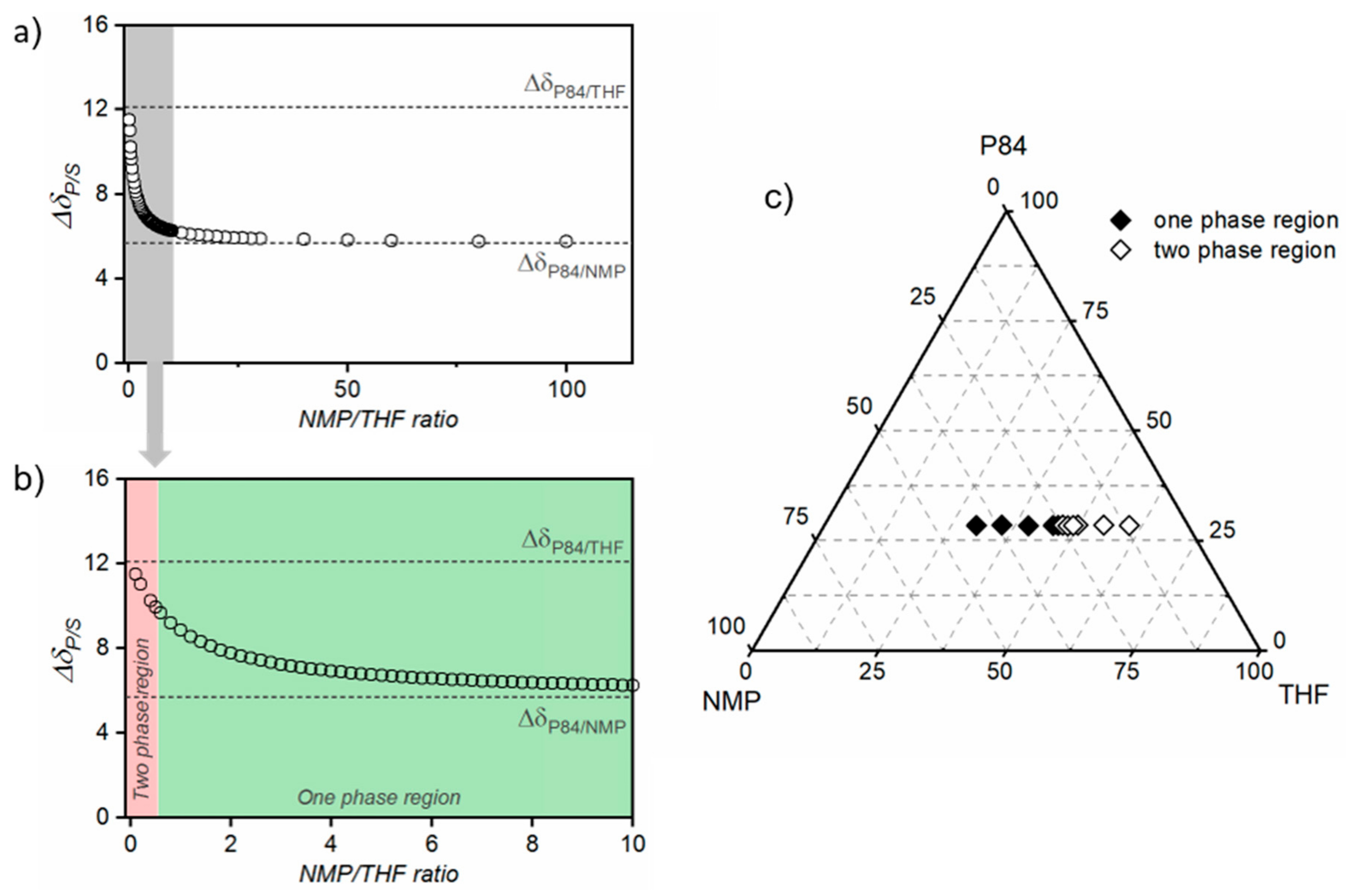
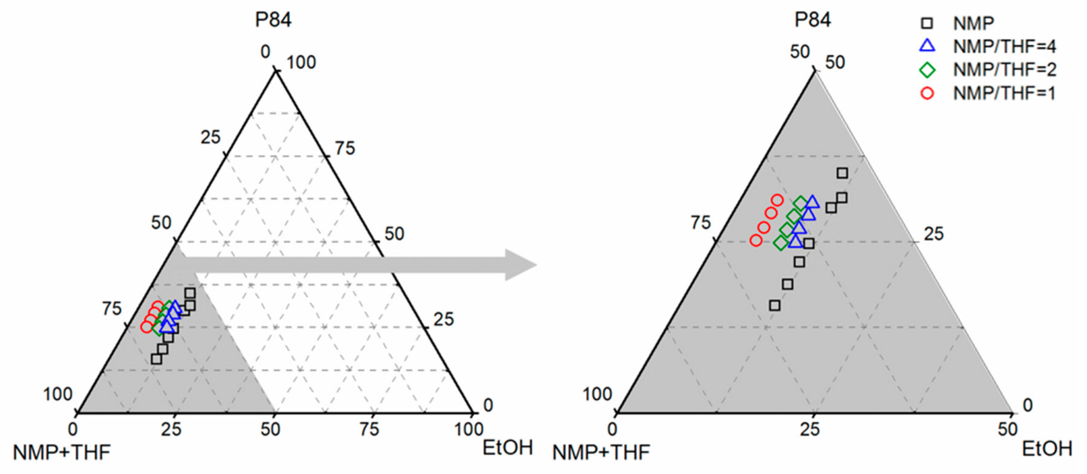
3.1.2. Ternary Phase Diagrams
3.2. P84® Hollow Fiber Spinning Process Optimization
3.2.1. P84®/NMP/EtOH Systems
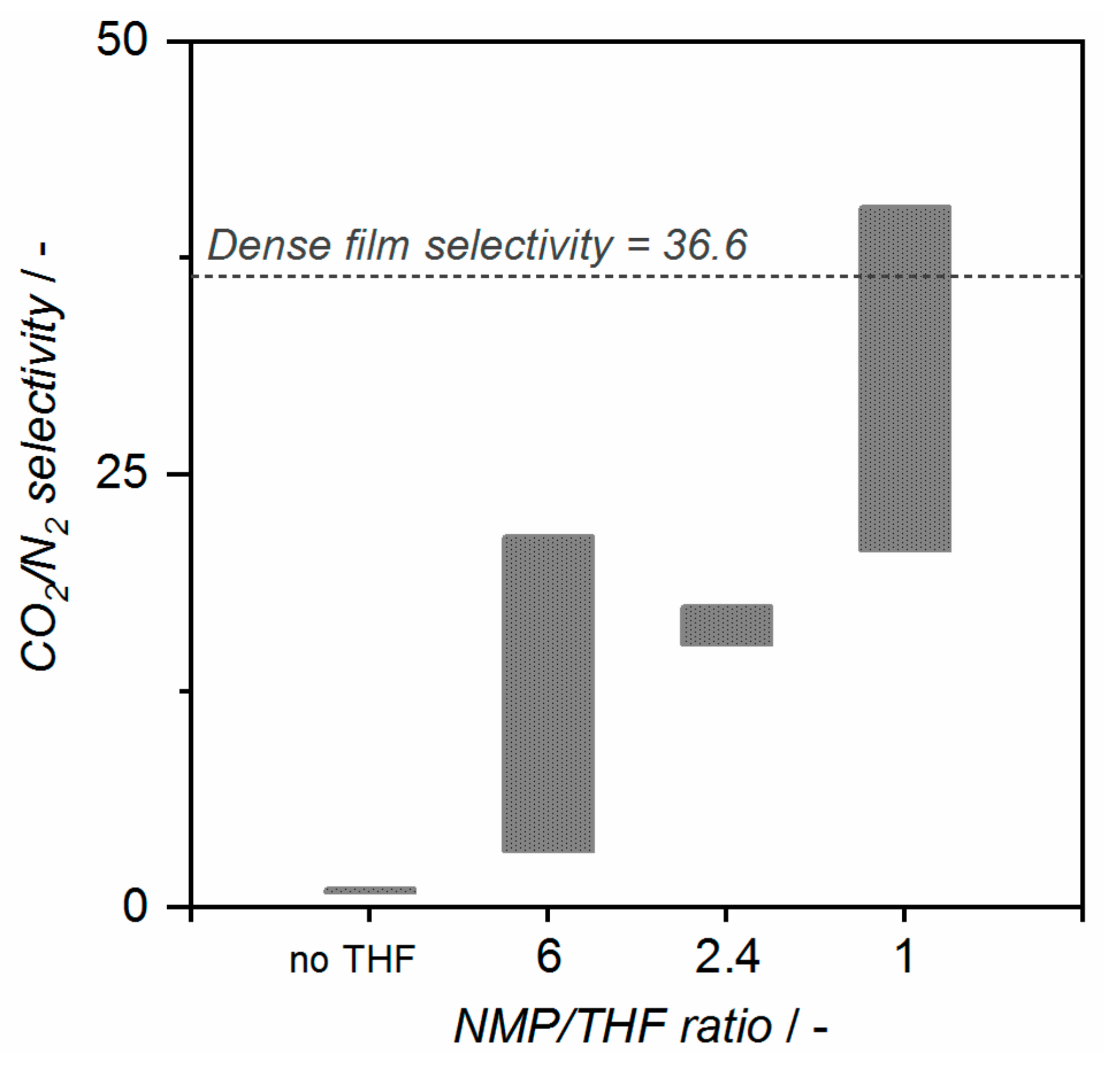
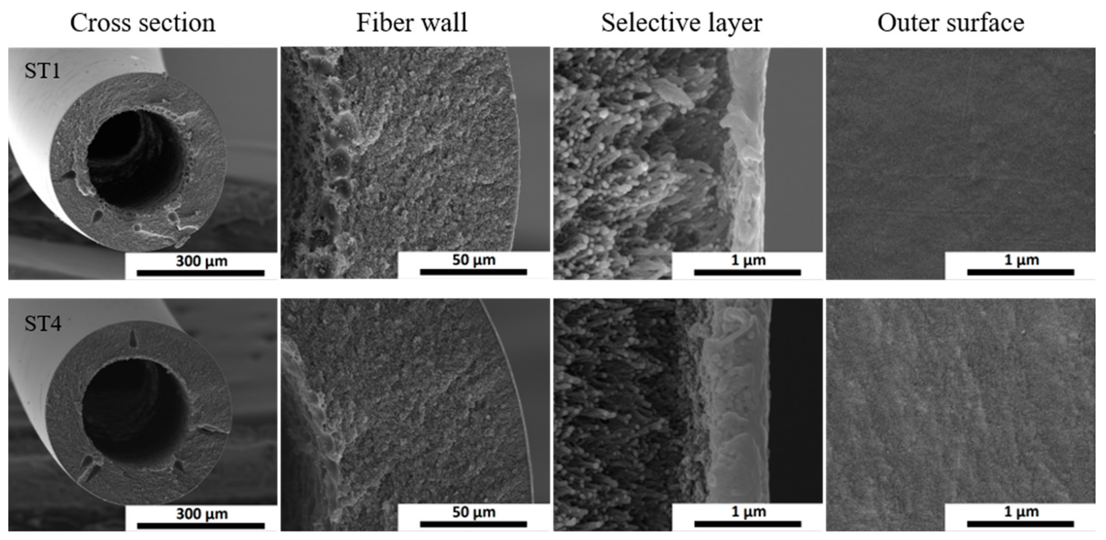
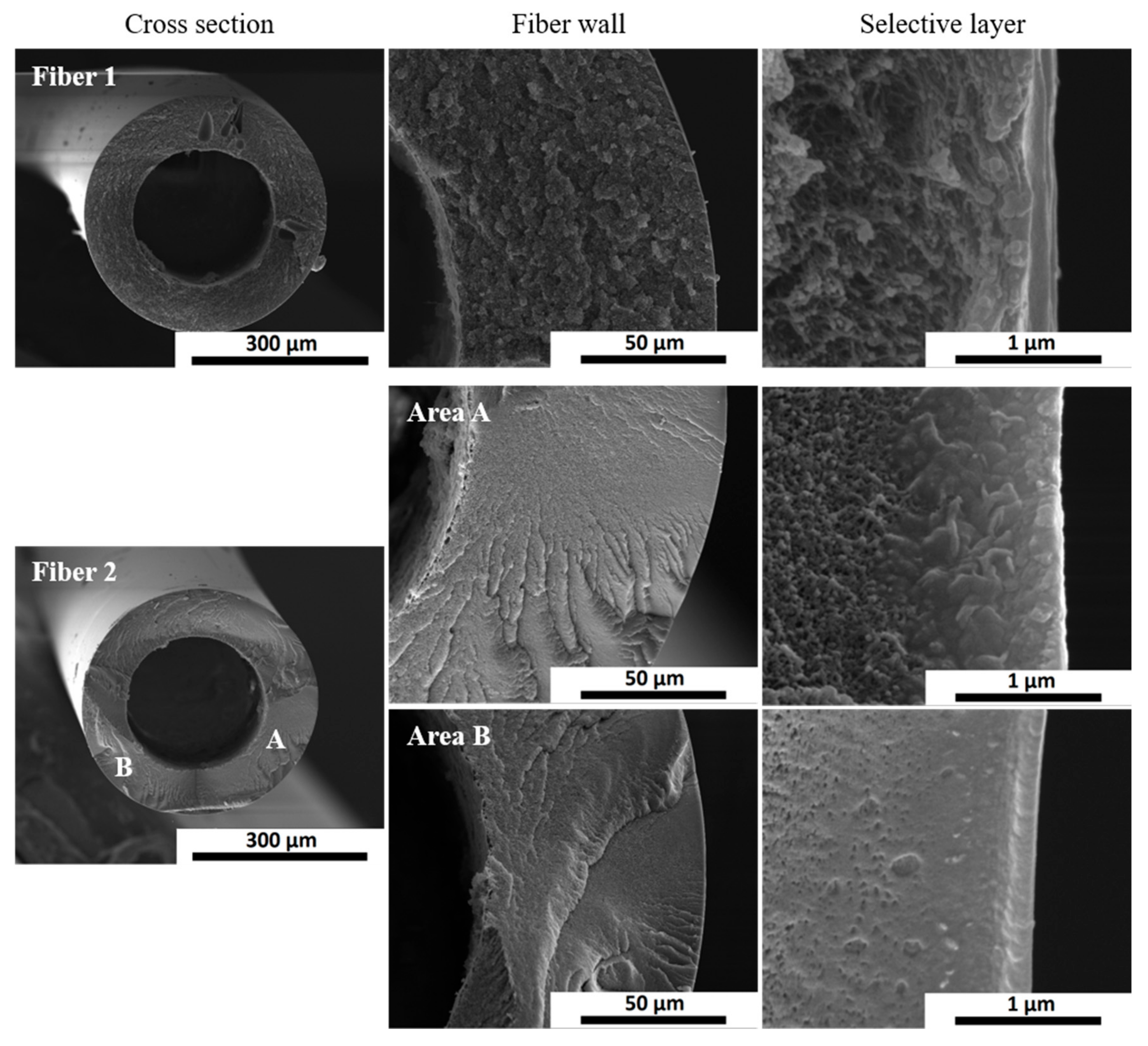
3.2.2. P84®/NMP/THF/EtOH Systems
4. Conclusions
Author Contributions
Funding
Conflicts of Interest
References
- Wahab, M.F.A.; Ismail, A.F.; Shilton, S.J. Studies on gas permeation performance of asymmetric polysulfone hollow fiber mixed matrix membranes using nanosized fumed silica as fillers. Sep. Purif. Technol. 2012, 86, 41–48. [Google Scholar] [CrossRef]
- Husain, S.; Koros, W.J. Mixed matrix hollow fiber membranes made with modified HSSZ-13 zeolite in polyetherimide polymer matrix for gas separation. J. Membr. Sci. 2007, 288, 195–207. [Google Scholar] [CrossRef]
- Peng, N.; Widjojo, N.; Sukitpaneenit, P.; Teoh, M.M.; Lipscomb, G.G.; Chung, T.-S.; Lai, J.-Y. Evolution of polymeric hollow fibers as sustainable technologies: Past, present, and future. Prog. Polym. Sci. 2012, 37, 1401–1424. [Google Scholar] [CrossRef]
- Li, Y.; Chung, T.; Huang, Z.; Kulprathipanja, S. Dual-layer polyethersulfone (PES)/BTDA-TDI/MDI co-polyimide (P84) hollow fiber membranes with a submicron PES–zeolite beta mixed matrix dense-selective layer for gas separation. J. Membr. Sci. 2006, 277, 28–37. [Google Scholar] [CrossRef]
- Widjojo, N.; Chung, T.-S.; Kulprathipanja, S. The fabrication of hollow fiber membranes with double-layer mixed-matrix materials for gas separation. J. Membr. Sci. 2008, 325, 326–335. [Google Scholar] [CrossRef]
- David, O.; Gendel, Y.; Wessling, M. Tubular macro-porous titanium membranes. J. Membr. Sci. 2014, 461, 139–145. [Google Scholar] [CrossRef]
- David, O.C.; Gorri, D.; Nijmeijer, K.; Ortiz, I.; Urtiaga, A. Hydrogen separation from multicomponent gas mixtures containing CO, N2 and CO2 using Matrimid® asymmetric hollow fiber membranes. J. Membr. Sci. 2012, 419–420, 49–56. [Google Scholar] [CrossRef]
- Babu, V.P.; Kraftschik, B.E.; Koros, W.J. Crosslinkable TEGMC asymmetric hollow fiber membranes for aggressive sour gas separations. J. Membr. Sci. 2018, 558, 94–105. [Google Scholar] [CrossRef]
- Yampolskii, Y. Polymeric Gas Separation Membranes. Macromolecules 2012, 45, 3298–3311. [Google Scholar] [CrossRef]
- Peng, N.; Chung, T.-S.; Lai, J.-Y. The rheology of Torlon® solutions and its role in the formation of ultra-thin defect-free Torlon® hollow fiber membranes for gas separation. J. Membr. Sci. 2009, 326, 608–617. [Google Scholar] [CrossRef]
- Pinnau, I.; Koros, W.J. Gas-permeation properties of asymmetric polycarbonate, polyestercarbonate, and fluorinated polyimide membranes prepared by the generalized dry–wet phase inversion process. J. Appl. Polym. Sci. 1992, 46, 1195–1204. [Google Scholar] [CrossRef]
- Henis, J.M.S.; Tripodi, M.K. Composite hollow fiber membranes for gas separation: The resistance model approach. J. Membr. Sci. 1981, 8, 233–246. [Google Scholar] [CrossRef]
- Clausi, D.T.; Koros, W.J. Formation of defect-free polyimide hollow fiber membranes for gas separations. J. Membr. Sci. 2000, 167, 79–89. [Google Scholar] [CrossRef]
- Krol, J.J.; Boerrigter, M.; Koops, G.H. Polyimide hollow fiber gas separation membranes: Preparation and the suppression of plasticization in propane/propylene environments. J. Membr. Sci. 2001, 184, 275–286. [Google Scholar] [CrossRef]
- Visser, T. Mixed Gas Plasticization Phenomena in Asymmetric Membranes; University of Twente: Enschede, The Netherlands, 2006. [Google Scholar]
- Kosuri, M.R.; Koros, W.J. Defect-free asymmetric hollow fiber membranes from Torlon®, a polyamide–imide polymer, for high-pressure CO2 separations. J. Membr. Sci. 2008, 320, 65–72. [Google Scholar] [CrossRef]
- Peng, N.; Chung, T.S. The effects of spinneret dimension and hollow fiber dimension on gas separation performance of ultra-thin defect-free Torlon ® hollow fiber membranes. J. Membr. Sci. 2008, 310, 455–465. [Google Scholar] [CrossRef]
- Kase, Y. Gas Separation by Polyimide Membranes. Adv. Membr. Technol. Appl. 2008, 581–598. [Google Scholar] [CrossRef]
- Ba, C.; Langer, J.; Economy, J. Chemical modification of P84 copolyimide membranes by polyethylenimine for nanofiltration. J. Membr. Sci. 2009, 327, 49–58. [Google Scholar] [CrossRef]
- See-Toh, Y.H.; Silva, M.; Livingston, A. Controlling molecular weight cut-off curves for highly solvent stable organic solvent nanofiltration (OSN) membranes. J. Membr. Sci. 2008, 324, 220–232. [Google Scholar] [CrossRef]
- See Toh, Y.H.; Lim, F.W.; Livingston, A.G. Polymeric membranes for nanofiltration in polar aprotic solvents. J. Membr. Sci. 2007, 301, 3–10. [Google Scholar] [CrossRef]
- Vandezande, P.; Gevers, L.E.M.; Vankelecom, I.F.J. Solvent resistant nanofiltration: Separating on a molecular level. Chem. Soc. Rev. 2008, 37, 365–405. [Google Scholar] [CrossRef] [PubMed]
- Han, R.; Xie, Y.; Ma, X. Crosslinked P84 copolyimide/MXene mixed matrix membrane with excellent solvent resistance and permselectivity. Chin. J. Chem. Eng. 2019, 27, 877–883. [Google Scholar] [CrossRef]
- Han, R.; Xie, Y.; Ma, X.; Teng, D.; Zhang, S.; Jian, X. Preparation of poly(2,4,6-triaminopyrimidine-TMC)/P84 composite nanofiltration membrane with enhanced chlorine resistance and solvent resistance. J. Chem. Technol. Biotechnol. 2019, 94, 2838–2843. [Google Scholar] [CrossRef]
- Davood Abadi Farahani, M.H.; Chung, T.-S. Solvent resistant hollow fiber membranes comprising P84 polyimide and amine-functionalized carbon nanotubes with potential applications in pharmaceutical, food, and petrochemical industries. Chem. Eng. J. 2018, 345, 174–185. [Google Scholar] [CrossRef]
- Dutczak, S.M.; Tanardi, C.R.; Kopeć, K.K.; Wessling, M.; Stamatialis, D. “Chemistry in a spinneret” to fabricate hollow fibers for organic solvent filtration. Sep. Purif. Technol. 2012, 86, 183–189. [Google Scholar] [CrossRef]
- Polotskaya, G.; Putintseva, M.; Pulyalina, A.; Gofman, I.; Toikka, A. Impact of endometallofullerene on P84 copolyimide transport and thermomechanical properties. Polymers 2018, 10, 1108. [Google Scholar] [CrossRef] [Green Version]
- Shi, G.M.; Wang, Y.; Chung, T.-S. Dual-layer PBI/P84 hollow fibers for pervaporation dehydration of acetone. AIChE J. 2012, 58, 1133–1145. [Google Scholar] [CrossRef]
- Liu, R.; Qiao, X.; Chung, T.-S. The development of high performance P84 co-polyimide hollow fibers for pervaporation dehydration of isopropanol. Chem. Eng. Sci. 2005, 60, 6674–6686. [Google Scholar] [CrossRef]
- Qiao, X.; Chung, T.-S.; Pramoda, K.P. Fabrication and characterization of BTDA-TDI/MDI (P84) co-polyimide membranes for the pervaporation dehydration of isopropanol. J. Membr. Sci. 2005, 264, 176–189. [Google Scholar] [CrossRef]
- Qiao, X.; Chung, T.-S. Fundamental Characteristics of Sorption, Swelling, and Permeation of P84 Co-polyimide Membranes for Pervaporation Dehydration of Alcohols. Ind. Eng. Chem. Res. 2005, 44, 8938–8943. [Google Scholar] [CrossRef]
- Barsema, J.N.; Kapantaidakis, G.C.; van der Vegt, N.F.A.; Koops, G.H.; Wessling, M. Preparation and characterization of highly selective dense and hollow fiber asymmetric membranes based on BTDA-TDI/MDI co-polyimide. J. Membr. Sci. 2003, 216, 195–205. [Google Scholar] [CrossRef]
- Visser, T.; Masetto, N.; Wessling, M. Materials dependence of mixed gas plasticization behavior in asymmetric membranes. J. Membr. Sci. 2007, 306, 16–28. [Google Scholar] [CrossRef]
- Omidvar, M.; Stafford, C.M.; Lin, H. Thermally stable cross-linked P84 with superior membrane H2/CO2 separation properties at 100 °C. J. Membr. Sci. 2019, 575, 118–125. [Google Scholar] [CrossRef] [PubMed]
- Guo, A.; Ban, Y.; Yang, K.; Yang, W. Metal-organic framework-based mixed matrix membranes: Synergetic effect of adsorption and diffusion for CO2/CH4 separation. J. Membr. Sci. 2018, 562, 76–84. [Google Scholar] [CrossRef]
- Choi, S.-H.; Jansen, J.C.; Tasselli, F.; Barbieri, G.; Drioli, E. In-line formation of chemically cross-linked P84® co-polyimide hollow fibre membranes for H2/CO2 separation. Sep. Purif. Technol. 2010, 76, 132–139. [Google Scholar] [CrossRef]
- Favvas, E.P.; Papageorgiou, S.K.; Nolan, J.W.; Stefanopoulos, K.L.; Mitropoulos, A.C. Effect of air gap on gas permeance/selectivity performance of BTDA-TDI/MDI copolyimide hollow fiber membranes. J. Appl. Polym. Sci. 2013, 130, 4490–4499. [Google Scholar] [CrossRef]
- Sheng, L.; Ren, J.; Hua, K.; Li, H.; Feng, Y.; Deng, M. The enhancement of mechanical properties of P84 hollow fiber membranes by thermally annealing below and above Tg. J. Membr. Sci. 2019, 595, 117580. [Google Scholar] [CrossRef]
- Hansen, C.M. Hansen Solubility Parameters: A User’s Handbook, 2nd ed.; Press, C., Ed.; CRC Press: Boca Raton, FL, USA, 2007; ISBN 9780849372483. [Google Scholar]
- Van Krevelen, D.W.; te Nijenhuis, K. Properties of Polymers: Their Correlation with Chemical Structure; Their Numerical Estimation and Prediction from Additive Group Contributions, 4th ed.; Science, E., Ed.; Elsevier Science: Amsterdam, The Netherlands, 2009; ISBN 9780080915104. [Google Scholar]
- Etxeberria-Benavides, M.; Johnson, T.; Cao, S.; Zornoza, B.; Coronas, J.; Sanchez-Lainez, J.; Sabetghadam, A.; Liu, X.; Andres-Garcia, E.; Kapteijn, F.; et al. PBI mixed matrix hollow fiber membrane: Influence of ZIF-8 filler over H2/CO2 separation performance at high temperature and pressure. Sep. Purif. Technol. 2019, 116347. [Google Scholar] [CrossRef]
- Peng, N.; Chung, T.S.; Wang, K.Y. Macrovoid evolution and critical factors to form macrovoid-free hollow fiber membranes. J. Membr. Sci. 2008, 318, 363–372. [Google Scholar] [CrossRef]
- Xu, L.; Zhang, C.; Rungta, M.; Qiu, W.; Liu, J.; Koros, W.J. Formation of defect-free 6FDA-DAM asymmetric hollow fiber membranes for gas separations. J. Membr. Sci. 2014, 459, 223–232. [Google Scholar] [CrossRef]
- Soroko, I.; Lopes, M.P.; Livingston, A. The effect of membrane formation parameters on performance of polyimide membranes for organic solvent nanofiltration (OSN): Part A. Effect of polymer/solvent/non-solvent system choice. J. Membr. Sci. 2011, 381, 152–162. [Google Scholar] [CrossRef]
- Pesek, S.C.; Koros, W.J. Aqueous quenched asymmetric polysulfone membranes prepared by dry/wet phase separation. J. Membr. Sci. 1993, 81, 71–88. [Google Scholar] [CrossRef]
- Chung, T.-S.; Lin, W.-H.; Vora, R.H. The effect of shear rates on gas separation performance of 6FDA-durene polyimide hollow fibers. J. Membr. Sci. 2000, 167, 55–66. [Google Scholar] [CrossRef]
- Lively, R.P.; Dose, M.E.; Xu, L.; Vaughn, J.T.; Johnson, J.R.; Thompson, J.A.; Zhang, K.; Lydon, M.E.; Lee, J.-S.; Liu, L.; et al. A high-flux polyimide hollow fiber membrane to minimize footprint and energy penalty for CO2 recovery from flue gas. J. Membr. Sci. 2012, 423–424, 302–313. [Google Scholar] [CrossRef]


| Functional Group | Numbers | Fdi (J1/2 m3/2 mol−1) | Fpi (J1/2 m3/2 mol−1) | Ehi (J mol−1) | Vi (cm3 mol−1) |
|---|---|---|---|---|---|
| –CH3 | 0.8 | 420 | 0 | 0 | 21.9 |
| –CH2 | 0.2 | 270 | 0 | 0 | 16.4 |
| =CH– | 10 | 200 | 0 | 0 | 13.5 |
| =C– | 9.2 | 70 | 0 | 0 | 0.0 |
| –CO– | 5 | 290 | 770 | 2000 | 13.6 |
| –N= | 2 | 20 | 800 | 5000 | 6.9 |
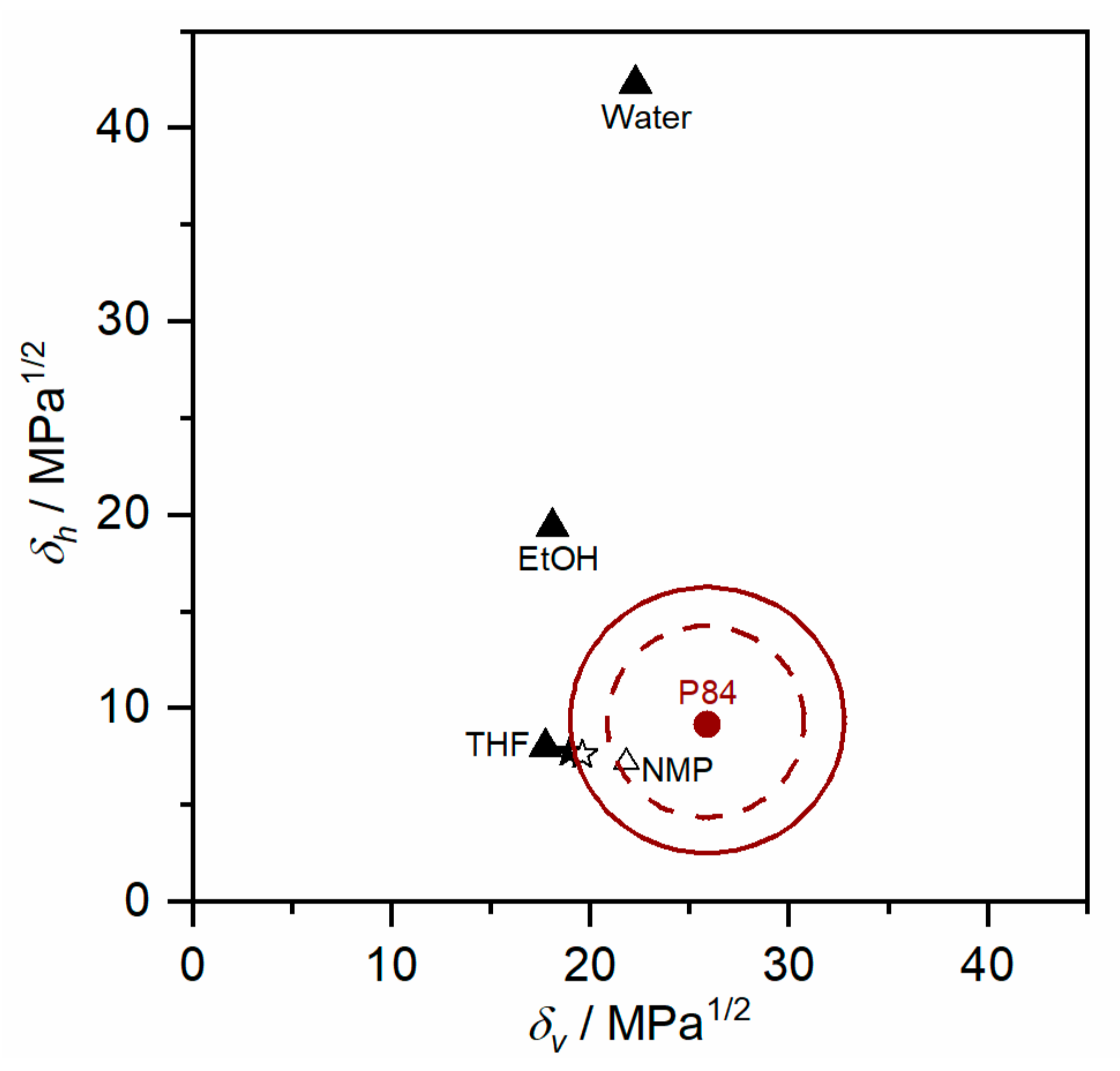
| Component | δd (MPa1/2) | δp (MPa1/2) | δh (MPa1/2) | δ (MPa1/2) | ∆δP/S (MPa1/2) |
|---|---|---|---|---|---|
| P84® | 19.0 | 17.5 | 9.17 | 27.5 | - |
| NMP | 18.0 | 12.3 | 7.20 | 23.0 | 5.69 |
| THF | 16.8 | 5.7 | 8.00 | 19.5 | 12.1 |
| EtOH | 15.8 | 8.80 | 19.4 | 26.5 | 13.8 |
| Water | 15.5 | 16 | 42.3 | 47.8 | 33.4 |
| Spinning Parameters | Unit | D1 | D2 | D3 | D4 | D5 |
|---|---|---|---|---|---|---|
| Dope composition | wt% P84® wt% NMP wt% THF wt% EtOH | 28.5 64.5 - 7 | 28.5 62.5 - 9 | 28.5 58.7 9.8 3 | 28 46.9 19.1 6 | 28.5 35.2 35.3 1 * |
| NMP/THF ratio | - | - | - | 6 | 2.4 | 1 |
| Dope/bore fluid flow rate | mL/h | 180/60 | 180/60 | 180/60 | 180/60 | 210/80, 240/90 |
| Bore fluid composition | NMP/H2O | 87.5/12.5 | 93/7, 85/15 | 84.5/15.5 | 84.8/15.2 | 87/13 |
| Spinneret temperature | °C | 25 | 30–40 | 25–30 | 25–30 | 25–40 |
| Air gap height | cm | 5–15 | 5–15 | 5–15 | 5–10 | 2–10 |
| Quench bath temperature | °C | 25 | 25 | 25 | 25 | 25 |
| Take up rate | m/min | 20–30 | 20–25 | 20–30 | 20–30 | 20 |
| Membrane Performance | Unit | D1 | D2 | D3 | D4 | D5 |
| CO2 permeance | GPU | 2269–1692 | 784–5692 | 79.9–193 | 28.2–34.9 | 3.53–23.0 |
| Ideal CO2/N2 selectivity | - | 0.98–1.08 | 0.87–1.09 | 3.28–21.4 | 15.2–17.4 | 20.6–40.4 |
| - | D5 | Unit | ST-1 | ST-2 | ST-3 | ST-4 |
| Spinning Parameters | Spinneret temperature | °C | 25 | 25 | 40 | 40 |
| Air gap height | cm | 2 | 10 | 2 | 10 | |
| Separation Performance | CO2 permeance | GPU | 23.0 ± 1.8 | 4.9 ± 0.1 | 12.0 ± 1.5 | 3.5 ± 0.1 |
| Ideal CO2/N2 selectivity | - | 40.4 ± 1.4 | 25.1 ± 0.4 | 34.8 ± 2.8 | 20.6 ± 0.25 | |
| Selective layer thickness (calculated from permeance) | nm | 56 | 262 | 107 | 363 |
| Separation Performance | Unit | D5_ST-1 | Up-Scale D5_ST-1 |
|---|---|---|---|
| CO2 permeance | GPU | 23.0 ± 1.8 | 8.4 ± 1.7 |
| Ideal CO2/N2 selectivity | - | 40.4 ± 1.4 | 39.1 ± 1.0 |
| Selective layer thickness (calculated from permeance) | nm | 56 | 152 |
© 2019 by the authors. Licensee MDPI, Basel, Switzerland. This article is an open access article distributed under the terms and conditions of the Creative Commons Attribution (CC BY) license (http://creativecommons.org/licenses/by/4.0/).
Share and Cite
Etxeberria-Benavides, M.; Karvan, O.; Kapteijn, F.; Gascon, J.; David, O. Fabrication of Defect-Free P84® Polyimide Hollow Fiber for Gas Separation: Pathway to Formation of Optimized Structure. Membranes 2020, 10, 4. https://doi.org/10.3390/membranes10010004
Etxeberria-Benavides M, Karvan O, Kapteijn F, Gascon J, David O. Fabrication of Defect-Free P84® Polyimide Hollow Fiber for Gas Separation: Pathway to Formation of Optimized Structure. Membranes. 2020; 10(1):4. https://doi.org/10.3390/membranes10010004
Chicago/Turabian StyleEtxeberria-Benavides, Miren, Oguz Karvan, Freek Kapteijn, Jorge Gascon, and Oana David. 2020. "Fabrication of Defect-Free P84® Polyimide Hollow Fiber for Gas Separation: Pathway to Formation of Optimized Structure" Membranes 10, no. 1: 4. https://doi.org/10.3390/membranes10010004