1. Introduction
To reduce greenhouse gas emissions, conventional power plants are increasingly replaced with decentralized renewable energy resources such as photovoltaic and wind power. This brings up new challenges. One major challenge is the requirement to keep a steady balance of demand and supply in order to keep the global grid frequency stable. Another major challenge is the requirement to avoid bottlenecks in distribution grids, and to keep their local voltage in the desired voltage band despite the increasing feed-in by renewable energy resources, and the also increasing share of electric mobility.
1.1. Demand Side Management
Demand Side Management (DSM) is repeatedly recognized to bear a high potential for efficiently matching demand and supply, and for dealing with bottlenecks in the distribution grid by adjusting the demand side [
1,
2].
Smart Metering Systems are a major component to realize DSM. They lay the foundation for the provision of load shifting incentives to the demand side, as well as for the verification of the response to these incentives. The reaction to load-shifting incentives such as price signals can be realized by manual human intervention. However, more advanced concepts involve Energy Management Systems (EMS) that automatically respond to DSM incentives by utilizing available flexibility with only marginal human interaction [
3]. Building Energy Management Systems (BEMS) are one example [
4,
5]. They may, e.g., optimize the charging and discharging of a photovoltaic-coupled battery storage system to increase the self-consumption of a building. In combination with
Smart Metering Systems, BEMS may also respond to external incentives from the grid-side, hence contributing to the grid stability and generating additional revenues for the building owner.
1.2. Smart Metering in Germany
Putting a high emphasis on standardization and security, the German smart metering approach is based on two major components:
Smart Meters, and
Smart Meter Gateways (SMGWs), whereby the combination of both is referred to as
Smart Metering System (“Intelligentes Messsystem”) [
6,
7]. The
Smart Meter itself is a digital power meter capable of providing temporal fine-grained power measurements, and has a display for visualizing energy values for different time frames. The SMGW is a communication device with two major functionalities. It can automatically communicate measurements from connected
Smart Meters to
External Market Participants (“Externe Marktteilnehmer”, EMP), and it allows EMPs to send incentives or commands for load adjustments to local control boxes such as EMSs. EMPs can be separated into passive EMPs that are receiving meter measurements or derived data only, and active EMPs that are also capable of sending commands to local control boxes [
8].
In the future,
Smart Meters will be compulsory for new installations, and according to the
German Metering Point Operation Law (“Messstellenbetriebsgesetz”, MsbG) [
6] the installation of SMGWs follows a step-wise roll-out plan, ultimately making it compulsory for consumers above 6000 kWh/year, or for consumers with renewable feed-in above 7 kW
peak. For consumers falling below these thresholds, the SMGW is optional and, hence, also the option to automatically communicate
Smart Meter measurements to entities outside the building or to receive load-shifting incentives from external parties. In the following, unless explicitly stated otherwise, we refer to
Smart Meters simply as
meters.
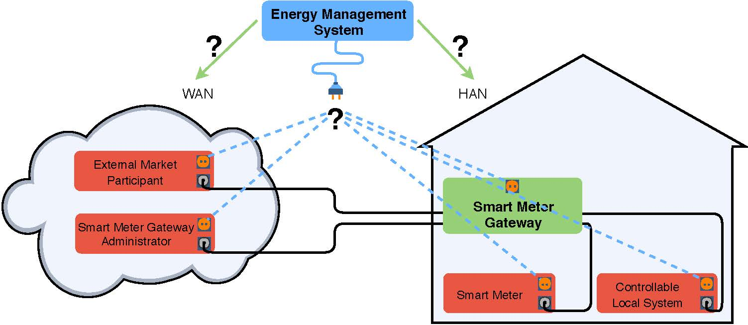
1.3. Smart Meter Gateways
SMGWs act as intermediary between the following three network areas through which they are connected to other devices and stakeholders [
7]:
Home Area Network (HAN): This network area is for the communication between the SMGW and Controllable Local Systems (CLSs) such as controllable devices or EMSs.
Local Metrological Network (LMN): This network area is for the communication between the SMGW and and Smart Meters.
Wide Area Network (WAN): This network area is for the communication between the SMGW, the associated EMPs and the SMGW Administrator.
SMGW Administrators are defined as trustworthy entities that are able to manage the encrypted and authenticated transport channels the SMGW uses to communicate with endpoints in the above network areas. Relying on a public key infrastructure (PKI) operated by the
German Federal Office for Information Security (“Bundesamt für Sicherheit in der Informationstechnik”, BSI) [
9], this is realized via
Communication Profiles described in
Section 3.
1.4. Contributions
The roll-out of Smart Metering Systems with standardized communication interfaces and access to meter measurements brings new opportunities for the efficient installation and operation of EMSs. However, EMSs relying on the SMGW architecture are subject to challenges and limitations introduced by mandatory specifications, e.g., regarding information flows and time granularities. In this paper, we present different options for the integration of EMSs into the German SMGW architecture. Therefore, we identify respective specifications, put them into relation, and point towards concrete requirements. We evaluate the proposed integration options regarding their pros and cons, and provide a discussion of trade-offs. This is in particular interesting for EMS designers that will be confronted with differing degrees of freedom and limitations depending on the integration option.
The paper is structured as follows.
Section 2 gives an overview of related work, in particular covering regulatory specifications.
Section 3 outlines the basic architectural requirements. Some additional billing-relevant requirements are presented in
Section 4. The different options for integrating one or more EMSs in a BSI-compliant fashion are illustrated in
Section 5 and then assessed in
Section 6. Finally, conclusions are drawn in
Section 7.
2. Related Work
This section provides an overview of regulations and specifications in the context of German Smart Metering Systems, references to related scientific work, and outlines the differences that distinguish the German approach from the approaches in other countries.
2.1. Legal Foundation: Act on the Digitization of the Energy Transition
In 2009, the European Parliament passed the
EU directive 2009/72 EC according to which the European Union’s member states have to roll-out smart metering infrastructures as basis for the realization of DSM measures [
10]. However, the rollout is only specified as compulsory for member states where benefits can be recognized. In Germany, Ernst & Young was charged to calculate potential benefits for different rollout scenarios in 2010 [
11]. As a result, in 2016, the German government passed the
German Act on the Digitization of the Energy Transition (“Gesetz zur Digitalisierung der Energiewende”), which consists of various adaptations of existing laws and regulations, and the introduction of the new
German Metering Point Operation Law (“Messstellenbetriebsgesetz”, MsbG). The MsbG regulates a compulsory rollout for a share of consumers in multiple phases until 2032 [
6]. By then, all households with an annual consumption above 6000 kWh or with renewable feed-in above 7 kW
peak have to have a
Smart Metering System as defined above, i.e., composed of a
Smart Meter coupled with an SMGW.
2.2. Technical Architecture: BSI Technical Guideline and Common Criteria Protection Profile
In Germany, technical requirements for
Smart Metering Systems are defined by the
German Federal Office for Information Security (“Bundesamt für Sicherheit in der Informationstechnik”, BSI), which published the first version of the technical guideline
BSI TR-03109 [
12] in 2014. Currently composed of five closely related sub-guidelines (TR-03109-x), it describes in detail the SMGW architecture with the three network areas (HAN, LMN, and WAN) introduced in
Section 1.3. Part 1 describes the functionality of the SMGW, interoperability aspects, and tariff use cases [
7]; Part 2 describes a dedicated security module for SMGWs, targeting at the secure handling of cryptographic functionalities [
13]; Part 3 describes cryptographic requirements for the SMGW [
14]; Part 4 describes the public-key-infrastructure for entities in the SMGW ecosystem [
9]; and Part 6 describes the SMGW administration via the new role of the
SMGW Administrator [
15]. Part 5 is supposed to address a communication adapter that allows the integration of meters that are not LMN-compatible natively. However, it is announced as being in the planning stage and not yet published. Regarding security aspects, the BSI further defines a
Common Criteria (CC) protection profile for the SMGW, referenced as
BSI-CC-PP-0073-2014 [
16]. It defines security objectives and security related requirements for the SMGW. Specified as CC Evaluation Assurance Level (EAL) 4, the CC protection profile follows the goal of certifying that an SMGW was methodically designed, tested and reviewed. According to § 22 and § 24 MsbG, SMGWs have to be certified by the BSI according to the BSI CC-PP-0073-2014 (ensuring the compliance with security related requirements), and according to the BSI TR-03109 (ensuring the compliance with technical and interoperability related requirements). According to § 30 MsbG [
6], the basic condition for the rollout of
Smart Metering Systems is the successful certification of SMGWs from at least three different manufacturers.
2.3. Handling of Metrological Data: PTB Specification
As the SMGW deals with metrological data which, among others, are used for billing purposes, legal requirements with respect to the
German Measurement and Calibration Law (“Mess- und Eichgesetz”, MessEG) have to be met [
17]. To reflect new technological developments in the context of
Smart Metering Systems, an amendment of the MessEG has been passed in 2013, with validity from 2015 onwards. Based on this, the
German National Metrology Institute (“Physikalisch-Technische Bundesanstalt”, PTB) defined technical requirements regarding the acquisition and processing of metrological data by the SMGW. These have been published in the requirements document
PTB-A50.8 in 2014 [
18]. Among others, the document defines the need for a display (for the verification of utility bills by comparison with local meter measurements), and a trustworthy time server architecture (for guaranteeing the assignment of valid timestamps to meter measurements). SMGWs as nationally regulated devices within the meaning of the MessEG have to comply with these requirements and have to obtain a type-examination certificate (“Baumusterprüfbescheinigung”) according to the
PTB-A50.8, in order to grant the permission to be deployed in practice.
2.4. Interoperable Implementations: FNN Requirements Specifications
Regarding the practical implementation of SMGWs, the
Forum Grid Technology/Grid Operation (“Forum Netztechnik/Netzbetrieb”, FNN) within the
German Association for Electrical, Electronic & Information Technologies (“Verband der Elektrotechnik, Elektronik und Informationstechnik”, VDE) works on specifications to ensure the efficient and interoperable grid operation in the context of various stakeholders. Members of the FNN are from different sectors (including, e.g., grid operators, device manufacturers, installers, plant operators, or authorities) and want to align their interests and interfaces. Results of the FNN are published in the form of application rules (“VDE-Anwendungsregeln”) or suggestions (“FNN-Hinweis”), neither of which, however, is legally binding. While the
BSI TR-03109 defines the technical SMGW architecture on a conceptual level, the FNN specifies minimum requirements for the inter-operable and manufacturer-independent operation of
Smart Metering Systems on the implementation level [
19]. This covers specifications for SMGW firmware processes [
20], and other SMGW related processes such as the ordering and configuration of SMGWs with cryptographically signed keys [
21], or the constructive hardware design. By implementing SMGWs on basis of the respective FNN specifications, manufacturers benefit from decisions that are aligned with a broad set of relevant stakeholders.
2.5. Application of the SMGW for the Implementation of Value-Added Services
One major purpose of
Smart Metering Systems is the enablement of Demand Side Management. In addition, the German SMGW approach with a dedicated communication gateway that ensures a trustworthy communication between external parties in the WAN (EMP) and internal devices in the HAN (CLS), sets the foundation for further use cases that are not necessarily energy-related, e.g., in the area of building automation. However, scientific work addressing value-added services in the context of the German SMGW architecture is rare, and related work in the context of Demand Side Management is mostly not considering a specific smart metering infrastructure. Possibilities for the integration of building automation applications (“smart home”) into the SMGW architecture based on the open-source project openHAB are discussed in [
22]. The paper proposes to define devices that are controllable via openHAB as CLS in the SMGW’s HAN. In [
23], different use cases built upon the SMGW architecture are discussed for regulated services, such as energy usage visualization, and for non-regulated services, such as virtual power plants. In the research project “CLS App” [
24], use cases for the application of CLS control boxes for energy management purposes, such as battery storage control, electric vehicle charging, or feed-in-management, are discussed with an emphasis on implementation aspects. In [
25], a Java-based open-source SMGW experimentation framework (jOSEF) is presented as tool for validating smart metering communication use cases involving SMGWs.
2.6. Comparison of the German Smart Metering Approach with Implementations in Other Countries
Implementations of smart metering approaches differ largely between countries. For member states of the European Union, a comparison can be found in [
26]. Among other things, implementations differ regarding functionality and interfaces, expected deployment strategies (partial rollout vs. full rollout), the market model (market-driven vs. regulated), the targeted diffusion rates, rollout time frames, or expected costs. The German approach with a dedicated and highly regulated communication gateway (SMGW) in addition to the meters can be seen as rather unique, compared to other countries. In [
27], background information on the privacy debate between 2010 and 2016 is given, pointing out critical aspects resulting in Germany’s current smart metering architecture with SMGWs. Due to requirements that are defined and verified by the BSI as German authority and due to national regulations, it is adapted to the German market. However, the overall concept, mechanisms and implementation of the SMGW as a gateway securing the communication between LMN, HAN and WAN could be applied to different countries, when countries adapt their national regulations accordingly. For instance, in [
28], the Swiss Federal Office of Energy evaluated the appropriateness of different smart metering approaches by defining minimum national requirements and comparing them with implementations in other countries, resulting in a large overlap between the Swiss requirements and the German approach. A broader comparison of national smart metering implementations can be found in the smart metering landscape report by the Austrian Energy Agency in [
29]. Among other things, the report categorizes national smart metering implementations regarding their overall strategy and regulatory basics.
3. Key Aspects of the BSI Technical Guideline with Relevance for Energy Management
Regarding energy management, the SMGW has two key functions. First, the gateway collects meter readings and provides the readings and other derived information to the consumers and EMPs. Second, it is able to create a transparent data tunnel allowing EMPs to communicate with CLSs. This section outlines these two key functions based on the BSI technical guideline
TR-03109-1 [
7] in order to draw conclusions about the integration of EMSs into the German smart metering architecture.
3.1. Configuration of the SMGW via Processing Profiles
The SMGW is configured by the
SMGW Administrator [
15] using so-called
Processing Profiles [
16]. The following types of profiles determine how the SMGW collects and processes measurements from meters:
Meter Profile: The Meter Profiles specify how an SMGW interacts with a Smart Meter. Among others, it configures the unique meter identifier, which protocol to use, which measurement registers to collect, information regarding encryption, and whether the communication is unidirectional or bidirectional. It also configures the time interval in which an SMGW must receive or request the measurements and update the internally saved latest meter reading.
Examination Profile: The
Examination Profiles specify which data need to be derived from the meter measurements. This is done by configuring a tariff use case (see
Section 3.3) and the respective parameters. Each examination profile contains a list of
Communication Profiles determining the recipient of the generated data.
Communication Profiles: There are different Communication Profiles for the HAN and the WAN. In both cases, the profiles define connection details that specify how to reach a communication partner based on uniform resource identifiers (URIs).
For each of the three profile types, multiple instances may be configured, e.g., multiple Meter Profiles to collect measurements from multiple meters.
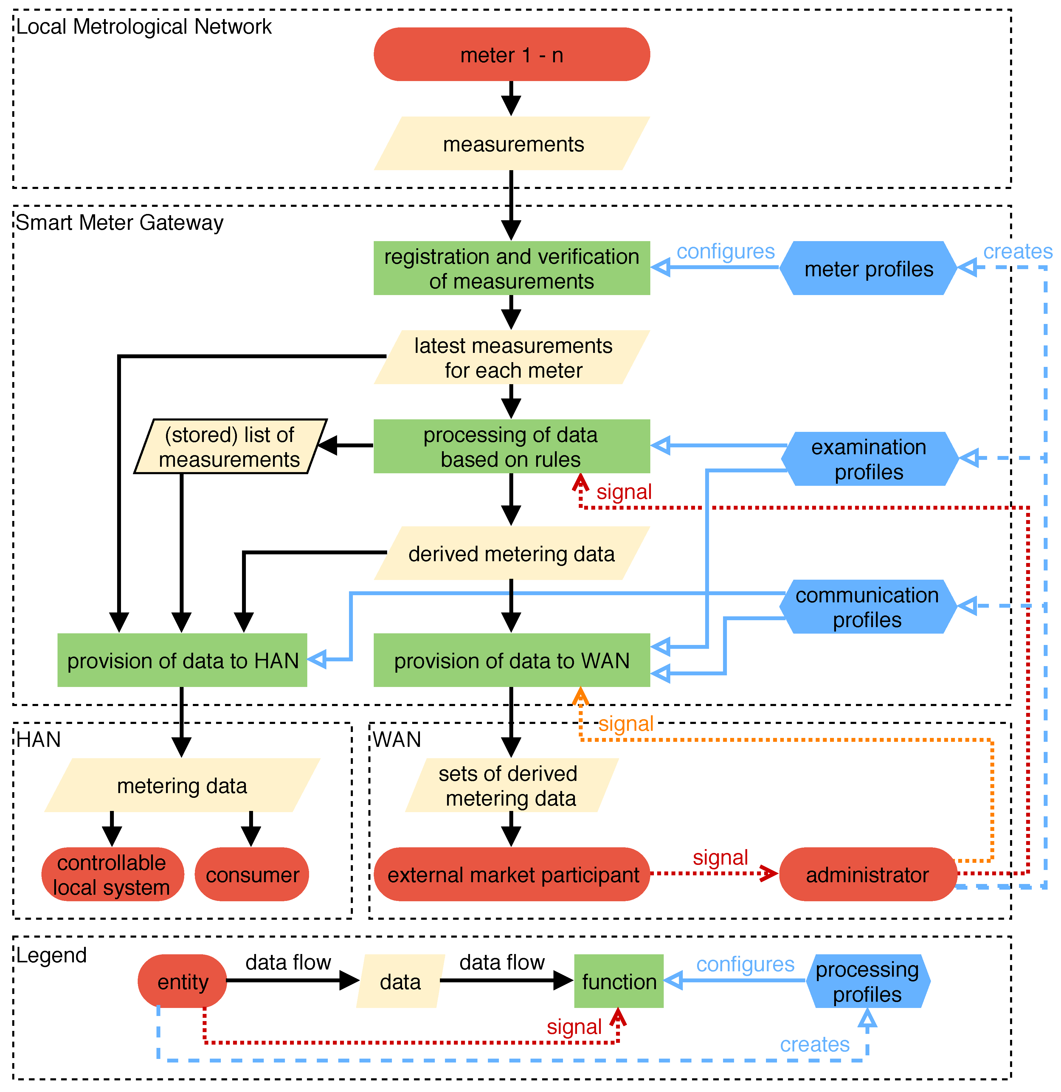
3.2. Processing of Measurements
Meter measurements are either received or requested based on the
Meter Profile. Even though we focus on electricity and mention deviating requirements for gas, an SMGW can also support other types of meters, such as meters for water and heat. After collecting the measurements, the SMGW must assess their correctness, check the status information sent by the meter and check its own status. If an issue is detected, the SMGW pushes a message to the
SMGW Administrator and additionally, depending on the type of issue, to the respective EMP. The values most recently collected from the meters according to the configured
Meter Profiles are stored internally and treated as latest meter readings. These data are then processed according to the
Examination Profiles and the configured tariff use cases. An overview of the tariff use cases and the temporal resolution of the available data is given in
Table 1. To create transparency for the consumer, the measurements are collected in a list and stored for later access. The tariff specific data that are derived by the SMGW are then collected and eventually sent to the EMP configured in the respective
WAN Communication Profile.
Table 1 lists the triggers for transmitting derived metering data to an EMP. All registered measurements, processed input data and derived metering data can be accessed by the consumer via the
Consumer Interface (“Letztverbraucher-Schnittstelle”, see
Section 3.4). Although the technical guideline mentions an interface for CLSs to access metering data, it does not contain a definition of such an interface. Only interfaces for the consumer and the service technician are specified in document version 1.0 [
7]. Therefore, local systems can only access metering data handled by the SMGW using the
Consumer Interface. Since the SMGW is able to handle meters and tariffs for multiple consumers simultaneously, e.g., in the case of apartment buildings with different households, consumers are only able to access the data concerning themselves (see [
16] for more details). All processing profiles are created and managed by the
SMGW Administrator.
Figure 1 depicts the process from registering the measurements to providing the data to local and remote entities.
Concerning the availability of current meter readings provided by the SMGW, it is necessary to distinguish between entities within the WAN and entities within the HAN. An external party must act as an EMP in order to receive metering data. Inside the HAN only consumers can access the data relevant to them. A local EMS may use the Consumer Interface of the SMGW in order to fetch the latest registered measurements.
3.3. Tariff Use Cases
The technical guideline defines 13 tariff use cases (“Tarifanwendungsfall”, TAF) that specify requirements for the provision of data to an EMP and the consumer.
Table 1 provides an overview of the TAFs and outlines the theoretically achievable currentness of meter measurements based on the tariff use case descriptions in [
7]. Since the technical guideline provides only a name and an outline instead of an actual specification, the table omits TAF 13, which is intended for visualizing measurements for a consumer via the WAN interface. Depending on how this TAF will be defined in the future, it may be very relevant for providing data to a remote EMS.
Both billing period and registration period are TAF-specific parameters. The billing period is relevant to TAFs 1, 2, 3, 4, 5, 7, and 8, and determines the length of the individual time frames for which measurements and derived data need to be collected. Additionally, for TAFs 3, 4, 7, and 8, the registration period determines the temporal granularity of the (derived) metering data that are collected during a billing period. This means that, if applicable, the EMP receives data for each registration period once the billing period has passed. Except for TAFs 6, 9, and 10, the collected data are sent at the configured time of transmission. On the one hand, the specification does not provide clear restrictions for the time of transmission and the length of the billing period. On the other hand, it states that the SMGW must support measurement periods of 5 min and that the measurement period is to be understood as the smallest billing-relevant time frame [
7] (Footnote 4). This implies that billing periods or registration periods of 5 min must be supported. For the registration period, the SMGW must support a length of at least 15 min.
An SMGW does not necessarily support all TAFs presented in
Table 1. Instead, only the availability of TAFs 1, 2, 6, and 7 is guaranteed [
30]. Some tariff use cases do only provide very specific information to the EMP, since they are meant for distinct situations. An example is given by TAF 9, which transmits solely the latest feed-in power. For TAF 9, the technical guideline states the requirement of providing current data, but does not further specify the exact meaning in regards of architectural and technical limitations. It is also important to note that for some tariff use cases the EMP receives only information derived from the measurements in lieu of the actual meter readings. One example is TAF 3, which registers the energy consumption based on the magnitude of power currently consumed. Then, after the billing period, the EMP receives information about the consumption for each load level.
3.4. Consumer Interface
The
Consumer Interface is accessible inside the HAN. Its purpose is to give consumers insights into their personal consumption. To access the interface and the data the respective consumer’s credentials are required. Aside from the data specific to the tariff use case, the
Consumer Interface must allow access to additional information. A complete list can be found in [
7], whereby the most relevant items for energy management are:
In this context, it is not exactly clear to which extent “current” readings need to be up-to-date or whether it is sufficient to provide the last readings that have been registered according to the SMGW’s configuration. Theoretically, in the case of a bidirectional communication, the SMGW could request the latest meter readings from the respective meters whenever they are requested via the Consumer Interface.
It is important to note that there is no standardized protocol for the communication via the
Consumer Interface. Hence, for every SMGW a device-specific interface needs to be implemented. A possible solution to this issue is provided by the project “TRuDI—transparency and display software” (“Transparenz- und Display-Software”) [
31]. It aims to provide a manufacturer-independent and standardized displaying solution. The source code is available at [
31] and includes proprietary modules for communicating with the SMGWs of different manufacturers.
3.5. Availability of Metering Data
In summary, given the SMGW has been configured in a suitable way, i.e., meter measurements are collected sufficiently frequently, the Consumer Interface, which is located within HAN, allows detailed access to meter measurements as described above. Generally speaking, information available inside the WAN is more sparse, but depending on the tariff use case and how long billing and registration periods need to be, the EMP is also able to receive detailed meter readings every 15 min or less for electricity, and 60 min or less for gas.
3.6. Transparent Data Tunnel
The second key function relevant for energy management—besides access to meter readings—is the transparent data tunnel for communication between EMPs and CLSs. It is configured using
Proxy Communication Profiles. These profiles specify combinations of CLS and EMP that may use the data tunnel in order to communicate, and also hold the certificates necessary for authentication. There are three possible ways (identified as HKS3, HKS4 and HKS5, where HKS stands for HAN communication scenario (“HAN-Kommunikationsszenario”)) to initiate the establishment of a transparent data tunnel. First, the CLS may use a SOCKSv5 [
32] command to tell the SMGW to establish a connection (HKS3). Second, an EMP can trigger the establishment with the help of the
SMGW Administrator (HKS4). In this case, the EMP signals the
SMGW Administrator that a transparent data tunnel is needed. If there is no open
management connection between the
SMGW Administrator and the SMGW, a connection is initiated using the
wake-up service of the SMGW. Once the management connection is available, the
SMGW Administrator is able to trigger the tunnel establishment by the SMGW. Third, the SMGW itself may initiate the transparent data tunnel whenever a predefined event occurs, for instance time based or periodically (HKS5).
4. Additional Regulations by the German National Metrology Institute
In addition to the technical guideline published by the BSI, the PTB declared its own requirements that need to be met by an SMGW in order to use the recorded data for billing purposes. The requirements are detailed in the document
PTB-A 50.8 [
18]. It explicitly states that the SMGW is allowed to process and provide data that are not relevant to the
German Measurement and Calibration Law such as operating values (voltage and harmonics) or fine-grained meter measurements beyond PTB requirements [
18] (p. 11).
4.1. Requirements for Processing Meter Measurements
As opposed to the BSI technical guideline, which is partially open to interpretation with respect to measurement resolutions, the
PTB-A 50.8 clearly states at which temporal resolution meter measurements have to be collected for billing-relevant purposes. The relevant requirements are as follows [
18]:
- DA1.3:
In the case of a unidirectional communication of the meter measurements in the LMN, the SMGW must promptly receive and immediately process the data.
- DA1.4:
For communicating measurements in a bidirectional fashion, the SMGW must collect the data exactly every quarter hour for electricity and every hour for gas.
- DA6.1:
To allow a comparison of the meter readings registered by the gateway and the readings display on the actual meter, the SMGW must be able to receive (unidirectional case) or request (bidirectional case) the latest measurements rapidly and repeatedly, as often as the meter and the transport channel allow. The information is accessible via the Consumer Interface.
Even though DA6.1 states that the measurements need to be collected rapidly and as often as possible when requested via the Consumer Interface, the PTB-A50.8 adds a displaying interval to the Meter Profile which configures the interval for updating the stored measurements while accessed by the consumer.
4.2. Registration Period
Another important deviation from the BSI technical guideline is the use of the term
Registration Period. While the BSI technical guideline separates between an interval for collecting measurements in the
Meter Profile, and a
Registration Periods for TAFs in the
Examination Profile, the
PTB-A50.8 [
18] calls both parameters
Registration Period. Furthermore,
Registration Periods (in the sense of [
18]) are required to start at the quarter hour and hour mark, respectively, thus the measurements are registered at these points in time [
18] (ZT1.5 + ZT2.3).
In requirement
ZT1.1, the document states that the technical guideline sets a lower bound of 15 min for the registration period, i.e., the registration period must be 15 min or longer. The technical guideline, on the other hand, only states that registration periods of at least 15 min must be supported and there are no constraints for the interval in the
Metering Profile given. This also contradicts the statement that the smallest measurement period, which is allowed to be set to 5 min, is equivalent to the smallest billing-relevant time frame [
7] (Footnote 4). Nevertheless, for billing-relevant purposes, the
PTB-A50.8 and its requirements are paramount.
The
PTB-A 50.8 provides formulas to compute the shortest allowable registration periods based on the mode of communication, i.e., unidirectional or bidirectional, the measurement period of the meter, and the admissible tolerances. It is also clarified that only measurements received within a certain time frame around the end of a registration period are allowed to be considered for billing purposes. The definitions of all constraints can be found in [
18] (Appendix A3). However, measurements that do not satisfy the constraints are available via the
Consumer Interface.
5. Options for a BSI-Compliant Integration of EMS into Smart Metering Systems
As outlined before, it can be distinguished between the three network areas LMN, HAN, and WAN. The LMN is only used for the communication between the SMGW and meters. Hence, an EMS could be placed either locally in the HAN or remotely in the WAN. Inside the WAN, access to measurements is restricted to the data provided by the TAFs described above. Inside the HAN, access to fine-grained measurements is possible via the Consumer Interface which provides access to all measurement readings.
In this section, the options for integrating an EMS into the SMGW architecture are illustrated. We categorize the EMS integration options into two major classes:
a full integration which uses the SMGW for both the collection of meter measurements and the transparent data tunnel; and
a partial integration, which only uses the SMGW for the transparent data tunnel and relies on an additional measurement collector for the collection of meter measurements.
For the consumer using an EMS, the major benefit of a full integration is the fact that SMGW-established data tunnels between EMPs and local entities are always cryptographically secured based on the public-key infrastructure with X.509 certificates managed by the BSI [
9]. Additionally, when relying on the SMGW architecture, passive EMPs (that are receiving meter-based data only) are required to provide a security concept, and active EMPs (that are interacting with CLSs) additionally require a certification according to the information security standard ISO/IEC 27001 [
8]. Consequently, the use of SMGW-established data tunnels is beneficial for consumers who want to secure their data. However, the complexity is increased whenever an EMP is required, since either a contract with an existing EMP is needed or a certification in order to become an EMP has to be undergone. This is especially relevant to EMS providers who want to offer EMSs using the data tunnel to connect to the respective provider’s remote services. After the following introduction of different options for the two introduced classes, the upcoming
Section 6 provides an in-depth discussion of their specific pros and cons.
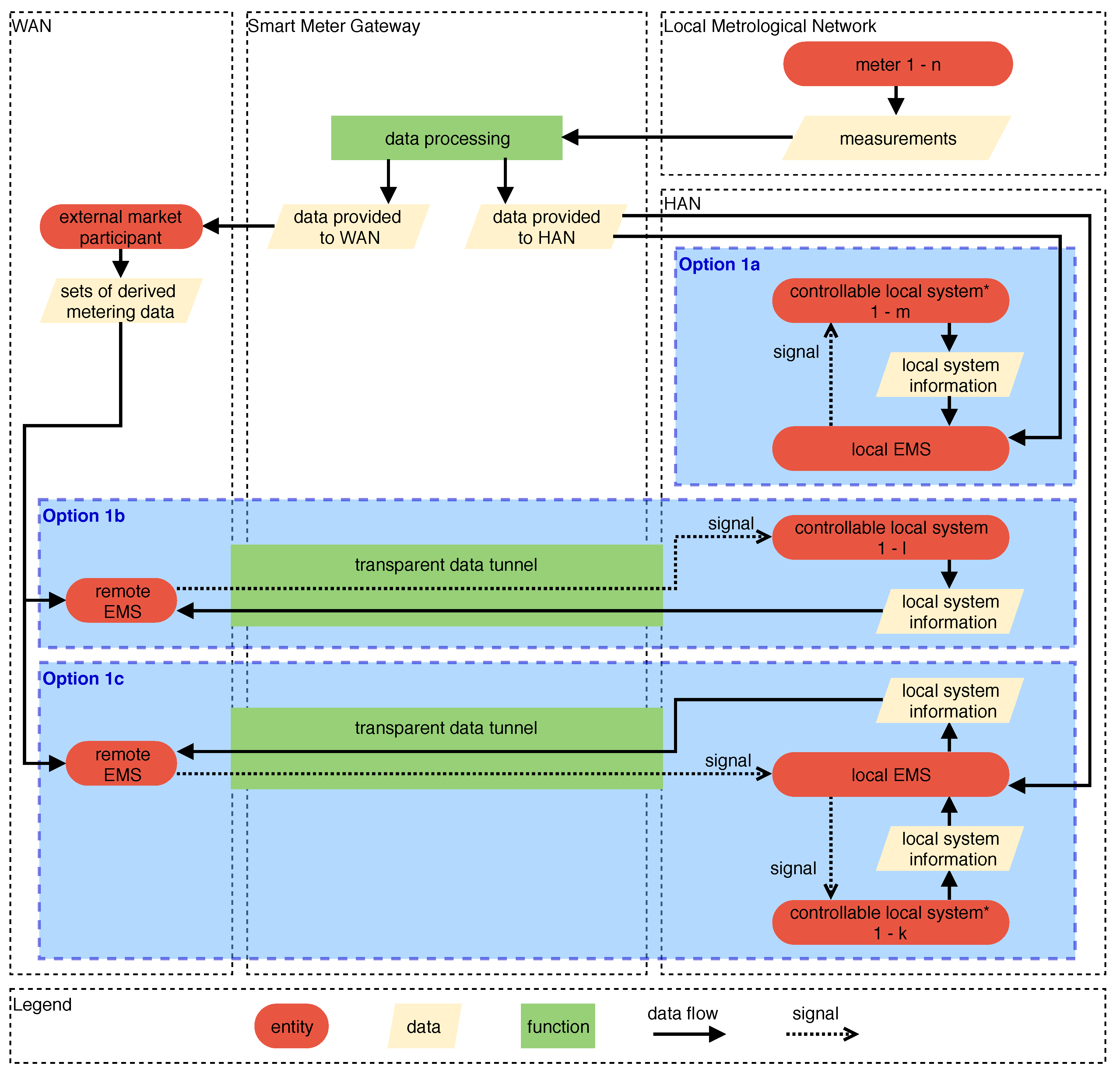
5.1. Full Integration Using the SMGW for the Collection of Meter Measurements and the Transparent Data Tunnel
First, we present options for a full integration that utilizes the SMGW for both the collection of meter measurements and the data tunnel between the HAN and the WAN. The regions outlined by the dashed blue boxes in
Figure 2 show the three basic options for a full EMS integration:
- Option 1a
is a local EMS inside the HAN (with no access to the WAN). It has the exclusive control over one or more CLSs. Meter measurements are collected from the HAN interface, i.e., the Consumer Interface, and additional information may be provided by the CLSs. Both information sources can be used for an optimization that results in signals to the CLSs, hence influencing their behavior.
- Option 1b
depicts the control of one or more CLSs by a remote EMS, i.e., an EMS located in the WAN. Using the mechanisms for accessing metering data provided by the technical guideline, a remote EMS can only retrieve metering data from the EMP. Hence, the EMS needs to either be part of the EMP’s systems, or an interface between the EMP and the remote EMS is required. The meter measurements (or derived data) that are sent to the EMP, as well as the point in time when they are sent, is defined by the configured TAF (see
Table 1). Based on remotely received data, the remote EMS uses the transparent data tunnel provided by the SMGW to send signals to control the CLSs inside the HAN. The data tunnel can be held open once it is established, however, a re-establishing may be required given certain events such as a loss of connection.
- Option 1c
is a combination of both Option 1a and Option 1b. A local EMS controls one or more CLSs but also shares information with a remote EMS (e.g., a regional EMS). The remote EMS in turn can use this information to send control signals to the local EMS. This way, a local EMS may utilize locally available information for controlling CLSs within boundaries provided by a remote EMS. The remote EMS may set the boundaries according its own optimization targets. This option also captures the possibility of the local EMS receiving measurements via the remote EMS instead of using the Consumer Interface.
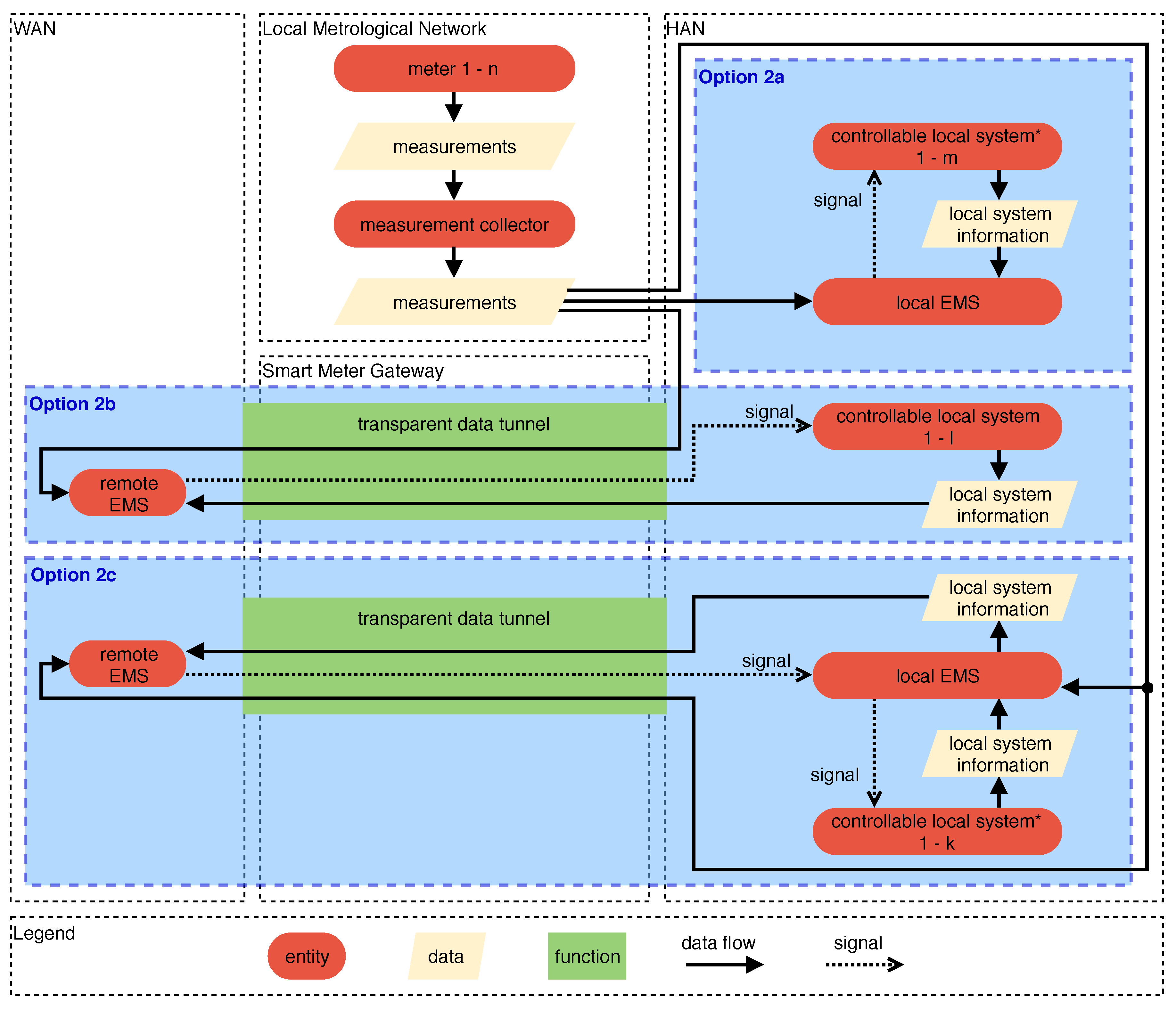
5.2. Partial Integration Using the SMGW Solely for the Transparent Data Tunnel
To not be bound to SMGW-related restrictions regarding meter measurements, the measurements can be collected locally directly from the Smart Meters by using a measurement collector. Such a measurement collector can be connected to the Smart Meter directly and independently from the SMGW. The measurement collector may be a standalone component, or it may be integrated into the local EMS. Hence, in these integration options, the SMGW—if used at all—is not involved in the collection of meter measurements for energy management. Instead, it acts solely as a gateway providing a transparent data tunnel. This data tunnel can be used bidirectionally to transmit measurements and local information to the remote EMS in the WAN and control signals to the CLSs and the local EMS in the HAN. The motivation for these integration options is to be free from the SMGW-related restrictions regarding meter measurements. However, while this potentially increases the range of possibilities, it potentially also decrease the quality and reliability of the collected data.
Analogously to
Figure 2,
Figure 3 shows three options for integrating an EMS by solely using the SMGW’s transparent data tunnel:
- Option 2a
describes the direct access to the meter measurements via a measurement collector that utilizes a Smart Meter interface. These measurements can be used by an EMS to control one or more CLSs. In this option, the local EMS is completely unaffected by the presence of an SMGW.
- Option 2b
is similar to Option 1b with the major difference that the meter measurements are collected by the local measurement collector. Via the transparent data tunnel, the measurements are provided to a remote EMS in the WAN which in turn sends control signals directly to one or more CLSs. Please note that this option still requires an EMP for setting up the transparent tunnel.
- Option 2c
is a combination of both, Options 2a and Option 2b. Similar to Option 2b, it uses the measurement collector to transmit the meter measurements to the remote EMS in the WAN. In this option, however, the remote EMS interacts with the local EMS, hence allowing a hierarchical control, as in the already presented Option 1c.
5.3. Partial Integration Using the SMGW Solely for the Collection of Measurements
Options that make use of SMGWs for collecting meter measurements but bypass the transparent data tunnel to communicate with a remote EMS are omitted in this paper, since they are similar to
Options 1a–c. All of the EMS integration options with a remote EMS introduced above, require the involvement of an
active EMP, i.e., an EMP with a valid BSI-issued X.509 certificate. An active EMP, according to Bundesamt für Sicherheit in der Informationstechnik [
9], needs a security concept, and additionally an ISO/IEC 27001 certification. When bypassing the data tunnel, non of this is needed. However, while this may reduce efforts, for example for the EMS provider, it reduces the security of the transport channel, hence resulting in potential drawbacks in particular for the consumer.
6. Assessment of EMS Integration Options
The exact requirements for executing energy management are case specific, although many energy management use cases require rather frequent access to measurements. Take for example a local battery storage system that has been installed to buffer surplus photovoltaic energy. In this case, a period of one or a few minutes may be acceptable, although more frequent measurements are desirable to improve the matching of the battery’s charging/discharging power with the photovoltaic generation and the local electricity consumption. On the other hand, an EMS controlling heating, ventilation and air conditioning may operate on timely more coarse-grained meter measurements as the respective decisions are more static due to a lower reaction speed and minimum runtimes requirements of related devices. Additionally, a local EMS may or may not interact with a remote EMS (such as a regional EMS providing DSM incentives that are, e.g., reflecting grid conditions).
6.1. Overview of the Different EMS Integration Options
In
Section 4, we point out that the requirements of the
PTB-A 50.8 are only mandatory for billing-relevant data processed by the SMGW. The
PTB-A 50.8 does not address the processing and provision of measurements that are not billing-relevant. Hence, for an automated energy management based on local meter measurements, only the weaker constraints of the
TR-03109-1 [
7] remain. Billing is still possible via setting up an interval for collecting measurements that still register the measurements at the quarter hour marks (hour marks respectively for gas), e.g., by using an interval of 1 min. Then, a (additional) TAF that complies with the
PTB-A 50.8 can be configured for billing purposes.
A summary of all presented options can be found in
Table 2. In regards to DSM, the options providing direct or indirect access to CLSs are relevant. For these, an active EMP and a transport channel for the communication between the SMGW and the EMP is required. Subsequently, we provide a more detailed assessment of the options. It has to be noted that the best EMS integration option is specific to the concrete energy management use case.
6.2. Discussion of EMS Integration Option 1a
In
Option 1a, the EMS makes use of the HAN interface of the SMGW, more precisely the
Consumer Interface, since it is the only defined local SMGW interface that provides measurement data in version 1.0 of the technical guideline [
7]. To access the interface, the credentials of the consumer are required. In future versions, SMGWs may be equipped with dedicated CLS interfaces providing local access to meter measurements. The frequency in which these measurements are received or requested is determined by the respective
Meter Profile using an interval in seconds. Considering solely the BSI technical guideline in version 1.0, the SMGW only needs to update the stored meter measurement according to the interval configured in the
Meter Profile. As the
PTB-A 50.8 is not mandatory for non-billing-relevant purposes, an SMGW is theoretically able to provide full access to the measurements provided by the meters via the
Consumer Interface.
There is one major disadvantage regarding data privacy in cases where the local EMS uses the Consumer Interface and also communicates with external third parties (such as a remote prediction service for photovoltaic generation) via the Internet. In such cases, the Smart Metering System’s architecture cannot guarantee that the EMS does not forward the fine-grained meter measurements available via the Consumer Interface to these third parties. Although possible, the usage of the Consumer Interface for such purposes is not intended by the BSI technical guideline as it poses a serious threat for data privacy.
6.3. Discussion of EMS Integration Option 1b
Option 1b does not utilize the HAN interface. Therefore, the only way to access measurements is via an EMP and the usage of an adequate TAF. TAF 13 for measurement visualization in the WAN could be very relevant, but has not been specified in the current version 1.0 of the BSI technical guideline [
7], aside from a short description. Given the TAFs in
Table 1, TAF 7 could be a suitable choice, especially since it is supported by the SMGWs of the first generation [
30]. Depending on the energy management use case, other TAFs may be applicable as well. Regardless of the TAF choice, fitting parameter values need to be configured. For TAF 7, the relevant parameters are the billing period, registration period, and the time of transmission. In addition, the
Meter Profile needs to configure an appropriate interval for collecting meter measurements. There is no clear statement in the technical guideline for the acceptable values for each of these parameters. It only briefly states that 5 min must be supported as a billing-relevant time frame [
7] (Footnote 4).
PTB-A 50.8, on the other hand, requires registration periods of 15 min or more. To realize use cases that need more frequent measurements, the TAF needs to be configured in a way such that the data must not be used for billing purposes. Due to the degrees of freedom provided by the BSI technical guideline, it is worth noting that there may be SMGW-specific differences regarding supported parameter values. For example, the
Meter Profiles of some SMGW implementations may allow specifying measurement intervals of under 900 s (15 min) while others do not.
In practice, the
SMGW Administrator’s systems also need to support the setup of the desired configuration. Given proper hardware and software platform choices, billing periods of less than 1 min are technically possible, although they are not allowed to be used for billing purposes according to the
PTB-A 50.8 requirements [
18]. Another factor to consider for a remote EMS is the communication standard used for the communication between EMP and SMGW. There are multiple options including Ethernet, Power Line Communication (PLC) and broadband cellular network technologies such as Long Term Evolution (LTE). Which of these are supported is device specific. While in general all of them may be an adequate choice, case specific solutions may be necessary. It is likely that in the future many SMGWs will use broadband cellular network technologies for WAN communication, although coverage and reliability may not be given everywhere. In this integration option, reliability of communication is especially important. The transparent data tunnel generally needs to be held open, as the reestablishment may take up to 50 s, depending on the implementation of the involved systems [
33]. Furthermore, it is necessary to assess the costs for hardware, EMP infrastructure and communication. Given these costs, using a remote EMS solely for the purpose of energy management may not be cost covering.
6.4. Discussion of EMS Integration Option 1c
Finally, as Option 1c is a combination of Option 1a and Option 1b, the sum of the above discussed characteristics have to be considered when integrating an EMS into the SMGW architecture. Additionally, it has to be considered that some SMGWs provide the HAN and CLS functionalities on different Ethernet ports. Then, the EMS has to be connected to the HAN port (which allows access to the Consumer Interface) and the CLS port (which allows the communication with the remote EMS) simultaneously.
6.5. Discussion of EMS Integration Options 2a, 2b and 2c
Options 2a, 2b and 2c bypass the meter data collection and processing of the SMGW. In cases where the SMGW is bypassed and both the SMGW and the EMS require access to meter measurements, optocouplers (using a meter’s optional infrared interface) are one possible solution for providing meter measurements to the EMS. The data acquisition process in Option 2b and Option 2c is essentially that of a utility sub-metering system. In these cases, the SMGW solely acts as a gateway between the HAN and the WAN in order to benefit from the secure communication channel.
It is important to note that the mechanisms defined in the BSI technical guideline are intended to provide a secure communication channel and to protect the data of consumers. Therefore, bypassing them is not the originally intended way to communicate measurements from the LMN to the WAN. However, based on the introduced regulations, we do not see any rules preventing an EMS designer from choosing these options that do not require to stick with the meter-specific requirements introduced by the BSI TR-03109 or the PTB-A 50.8. Since Option 2a also completely bypasses the SMGW, it is entirely independent from the presence of an SMGW.
7. Conclusions
As more and more SMGWs will be installed in Germany in the upcoming years, the topic of EMS and SMGW interaction will become increasingly relevant. Although the solution is currently exclusive to the German market, other countries may follow and implement similar approaches in the future. In this paper, we provide a structured overview of the requirements for German SMGWs that are important for energy management. We also illustrate relevant options to integrate an EMS into Smart Metering Systems in a BSI-compliant way, showing that a local EMS in the HAN, a remote EMS in the WAN, and even combinations of both are possible. Furthermore, we outline key factors that need to be considered when implementing the given options. A major challenge is the access to the latest meter measurements due to the respective requirements, as well as the lack of standardized interfaces. These issues will probably be addressed in the future. TRuDI, for example, is a first step in this direction, allowing to access the Consumer Interface of SMGWs from different manufacturers.
It is important to understand that the German Smart Metering System only sets the basis for a secure and reliable communication between local and remote entities. Information flows and details regarding CLS control are not defined. Future work may in particular address the balance between a centralized optimization performed by remote EMSs (e.g., operated by distribution grid operators), and a decentralized optimization performed locally (e.g., in buildings). The advancement of regulations regarding DSM incentives and flexibility markets, the optimizations performed by EMSs and their distribution, as well as interfaces of Smart Metering Systems go hand in hand. Consequently, new possibilities for the integration of EMSs into the SMGW architecture may come up in the future. In the presented German regulatory environment, this may be based on either new versions of the BSI technical guideline, or demand-driven SMGW advancements that provide further optional functionality considering the degrees of freedom provided by the relevant specifications.
Author Contributions
K.F. and M.L. conceived and designed the research; M.R. and R.N. developed the basic concept from which the options presented in this paper were derived; K.F. and M.L. derived the presented options, assessed them and wrote as well as polished the paper; R.N. helped in the assessment; and H.S. provided feedback, supervision, organization of funding and resources for this collaboration. All authors have read and approved the final manuscript.
Funding
We gratefully acknowledge the financial support from the Federal Ministry for Economic Affairs and Energy (BMWi) for the project C/sells (funding No. 03SIN121).
Conflicts of Interest
The authors would like to point out that two of the co-authors are employed by Power Plus Communications AG, a manufacturer of Smart Meter Gateways. However, this had no impact on the design of the study; the collection, analyses, or interpretation of data; the writing of the manuscript, or the decision to publish the results.
References
- Siano, P. Demand Response and Smart Grids—A Survey. Renew. Sustain. Energy Rev. 2014, 30, 461–478. [Google Scholar] [CrossRef]
- Strbac, G. Demand Side Management: Benefits and Challenges. Energy Policy 2008, 36, 4419–4426. [Google Scholar] [CrossRef]
- Palensky, P.; Dietrich, D. Demand Side Management: Demand Response, Intelligent Energy Systems, and Smart Loads. IEEE Trans. Ind. Inform. 2011, 7, 381–388. [Google Scholar] [CrossRef] [Green Version]
- Kosek, A.M.; Costanzo, G.T.; Bindner, H.W.; Gehrke, O. An Overview of Demand Side Management Control Schemes for Buildings in Smart Grids. In Proceedings of the IEEE International Conference on Smart Energy Grid Engineering, Oshawa, ON, Canada, 28–30 August 2013. [Google Scholar] [CrossRef]
- Zhou, B.; Li, W.; Chan, K.W.; Cao, Y.; Kuang, Y.; Liu, X.; Wang, X. Smart home energy management systems: Concept, configurations, and scheduling strategies. Renew. Sustain. Energy Rev. 2016, 61, 30–40. [Google Scholar] [CrossRef]
- Gesetz über den Messstellenbetrieb und die Datenkommunikation in Intelligenten Energienetzen. Messstellenbetriebsgesetz; MsbG. 2016. Available online: https://www.gesetze-im-internet.de/messbg/MsbG.pdf (accessed on 1 February 2019).
- Bundesamt für Sicherheit in der Informationstechnik. Technische Richtlinie BSI TR-03109-1: Anforderungen an die Interoperabilität der Kommunikationseinheit eines Intelligenten Messsystems. 2019. Available online: https://www.bsi.bund.de/SharedDocs/Downloads/DE/BSI/Publikationen/TechnischeRichtlinien/TR03109/TR03109-1.pdf (accessed on 1 February 2019).
- Bundesamt für Sicherheit in der Informationstechnik. Certificate Policy der Smart Metering PKI. 2017. Available online: https://www.bsi.bund.de/SharedDocs/Downloads/DE/BSI/Publikationen/TechnischeRichtlinien/TR03109/PKI_Certificate_Policy.pdf (accessed on 1 February 2019).
- Bundesamt für Sicherheit in der Informationstechnik. Technische Richtlinie BSI TR-03109-4: Smart Metering PKI—Public Key Infrastruktur für Smart Meter Gateways. 2017. Available online: https://www.bsi.bund.de/SharedDocs/Downloads/DE/BSI/Publikationen/TechnischeRichtlinien/TR03109/TR-03109-4_PKI.pdf (accessed on 1 February 2019).
- The European Parliament and European Council. Directive 2009/72/EC of the European Parliament and of the Council: Common Rules for the Internal Market in Electricity and Repealing Directive 2003/54/EC. 2009. Available online: https://eur-lex.europa.eu/legal-content/en/ALL/?uri=celex%3A32009L0072 (accessed on 1 February 2019).
- Ernst & Young. Kosten-Nutzen-Analyse Für einen flächendeckenden Einsatz Intelligenter Zähler. Studie im Auftrag des Bundesministeriums für Wirtschaft und Energie. 2013. Available online: https://www.bmwi.de/Redaktion/DE/Publikationen/Studien/kosten-nutzen-analyse-fuer-flaechendeckenden-einsatz-intelligenterzaehler.pdf (accessed on 16 January 2019).
- Bundesamt für Sicherheit in der Informationstechnik. Technische Richtlinie BSI TR-03109. 2015. Available online: https://www.bsi.bund.de/SharedDocs/Downloads/DE/BSI/Publikationen/TechnischeRichtlinien/TR03109/TR03109.pdf (accessed on 16 January 2019).
- Bundesamt für Sicherheit in der Informationstechnik. Technische Richtlinie BSI TR-03109-2: Smart Meter Gateway—Anforderungen an die Funktionalität und Interoperabilität des Sicherheitsmoduls. 2014. Available online: https://www.bsi.bund.de/SharedDocs/Downloads/DE/BSI/Publikationen/TechnischeRichtlinien/TR03109/TR-03109-2-Anforderungen_an_die_Funktionalitaet.pdf (accessed on 1 February 2019).
- Bundesamt für Sicherheit in der Informationstechnik. Technische Richtlinie TR-03109-3 Kryptographische Vorgaben für die Infrastruktur von Intelligenten Messsystemen. 2014. Available online: https://www.bsi.bund.de/SharedDocs/Downloads/DE/BSI/Publikationen/TechnischeRichtlinien/TR03109/TR-03109-3_Kryptographische_Vorgaben.pdf (accessed on 1 February 2019).
- Bundesamt für Sicherheit in der Informationstechnik. Technische Richtlinie BSI TR-03109-6: Smart Meter Gateway Administration. 2015. Available online: https://www.bsi.bund.de/SharedDocs/Downloads/DE/BSI/Publikationen/TechnischeRichtlinien/TR03109/TR-03109-6-Smart_Meter_Gateway_Administration.pdf (accessed on 1 February 2019).
- Bundesamt für Sicherheit in der Informationstechnik. BSI-CC-PP-0073-2014: Protection Profile for the Gateway of a Smart Metering System/Schutzprofil für die Kommunikationseinheit eines Intelligenten Messsystems für Stoff- und Energiemengen. 2014. Available online: https://www.bsi.bund.de/SharedDocs/Downloads/DE/BSI/Zertifizierung/Reporte/ReportePP/pp0073b_pdf.pdf (accessed on 15 January 2019).
- Gesetz über das Inverkehrbringen und die Bereitstellung von Messgeräten auf dem Markt, ihre Verwendung und Eichung sowie über Fertigpackungen. Mess- und Eichgesetz, MessEG. 2013. Available online: https://www.gesetze-im-internet.de/messeg/BJNR272300013.html (accessed on 1 February 2019).
- Physikalisch-Technische Bundesanstalt. PTB-Anforderungen PTB-A 50.8: Smart Meter Gateway. 2014. Available online: https://oar.ptb.de/files/download/56d6a9e2ab9f3f76468b4618 (accessed on 7 January 2019).
- Forum Netztechnik/Netzbetrieb im VDE. FNN-Hinweis: Lastenheft Smart-Meter-Gateway Funktionale Merkmale. 2016. Available online: https://shop.vde.com/de/copy-of-fnn-hinweis-lastenheft-smart-meter-gateway-funktionale-merkmale (accessed on 15 January 2019).
- Forum Netztechnik/Netzbetrieb im VDE. FNN-Hinweis Lastenheft Mikroprozesse für das Smart Meter Gateway, Typ G1. 2016. Available online: https://shop.vde.com/de/fnn-hinweis-lastenheft-mikroprozesse-f%C3%BCr-das-smart-meter-gateway-typ-g1-2 (accessed on 15 January 2019).
- Forum Netztechnik/Netzbetrieb im VDE. FNN-Hinweis: Elektronischer Lieferschein für die Bestellung und Lieferung von Messeinrichtungen und Komponenten für Messsysteme. 2017. Available online: https://shop.vde.com/de/elektronischer-lieferschein-f%C3%BCr-messeinrichtungen-und-komponenten-f%C3%BCr-messsysteme (accessed on 15 January 2019).
- Freudenmann, C.; Henneke, D.; Kudera, C.; Kammerstetter, M.; Wisniewski, L.; Raquet, C.; Kastner, W.; Jasperneite, J. Open and Secure: Amending the Security of the BSI Smart Metering Infrastructure to Smart Home Applications via the Smart Meter Gateway. In Smart Energy Research. At the Crossroads of Engineering, Economics, and Computer Science; Derksen, C., Weber, C., Eds.; Springer International Publishing: Cham, Switzerland, 2017; pp. 136–146. [Google Scholar] [CrossRef]
- Meister, J.; Ihle, N.; Lehnhoff, S.; Uslar, M. 10—Smart grid digitalization in Germany by standardized advanced metering infrastructure and green button. In Application of Smart Grid Technologies; Lamont, L.A., Sayigh, A., Eds.; Academic Press: London, UK, 2018; pp. 347–371. [Google Scholar] [CrossRef]
- Heß, S.; Kaufmann, T.; Riedinger, T.; Wening, J.; Schindlmeier, A.; Stern, K.; Heilscher, G.; Lorenz, H.; Chen, S.; Binder, J.; et al. Forschungsbericht CLS-App BW, CLS-Applikation—Digitalisierung Energiewende Made in BW. 2018. Available online: http://fachdokumente.lubw.baden-wuerttemberg.de/servlet/is/123624/?COMMAND=DisplayBericht&FIS=203&OBJECT=123624&MODE=METADATA (accessed on 1 February 2019).
- Hoefling, M.; Heimgaertner, F.; Fuchs, D.; Menth, M. jOSEF: A Java-Based Open-Source Smart Meter Gateway Experimentation Framework. In Energy Informatics; Gottwalt, S., König, L., Schmeck, H., Eds.; Springer International Publishing: Cham, Switzerland, 2015; pp. 165–176. [Google Scholar] [CrossRef]
- European Commission, Joint Research Centre. Smart Electricity Systems and Interoperability. Smart Metering Deployment in the European Union. Available online: https://ses.jrc.ec.europa.eu/smart-metering-deployment-european-union (accessed on 19 March 2019).
- Greveler, U. Die Smart-Metering-Debatte 2010–2016 und ihre Ergebnisse zum Schutz der Privatsphäre. Datenbank-Spektrum 2016, 16, 137–145. [Google Scholar] [CrossRef]
- Eidgenössisches Departement für Umwelt, Verkehr, Energie und Kommunikation UVEK, Bundesamt für Energie BFE. Grundlagen der Ausgestaltung einer Einführung Intelligenter Messsysteme beim Endverbraucher in der Schweiz Technische Mindestanforderungen und Einführungsmodalitäten. 2014. Available online: http://www.news.admin.ch/NSBSubscriber/message/attachments/37458.pdf (accessed on 19 March 2019).
- Hierzinger, R.; Albu, M.; van Elburg, H.; Scott, A.J.; Łazicki, A.; Penttinen, L.; Puente, F.; Sæle, H. European Smart Metering Landscape Report 2012. 2012. Available online: https://ec.europa.eu/energy/intelligent/projects/sites/iee-projects/files/projects/documents/smartregions_landscape_report_2012_update_may_2013.pdf (accessed on 19 March 2019).
- Bundesamt für Sicherheit in der Informationstechnik. Technische Richtlinie BSI TR-03109-1, Anlage VII: Interoperabilitätsmodell und Geräteprofile für Smart-Meter-Gateways. 2019. Available online: https://www.bsi.bund.de/SharedDocs/Downloads/DE/BSI/Publikationen/TechnischeRichtlinien/TR03109/TR-03109-1_Anlage_Interop-Modell-Geraeteprofile.pdf (accessed on 1 February 2019).
- Müller, T. TRuDI – Transparenz- und Display-Software. Available online: https://bitbucket.org/dzgtrudi/trudi-public (accessed on 18 March 2019).
- Leech, M.; Ganis, M.; Lee, Y.; Kuris, R.; Koblas, D.; Jones, L. SOCKS Protocol Version 5. RFC 1928. 1996. Available online: https://tools.ietf.org/html/rfc1928 (accessed on 11 January 2019).
- Estermann, T.; Müller, M.; Weiß, A.; Würtenberg, I. Steuerbox im Feldversuch—Umsetzung von Schalthandlungen mit der Zukünftigen Smart-Grid-Infrastruktur Bestehend aus Intelligentem Messsystem und Steuerbox. In Proceedings of the Conference on “Zukünftige Stromnetze für Erneuerbare Energien”, Berlin, Germany, 30–31 January 2018; Available online: https://www.ffe.de/attachments/article/765/Paper_Steuerbox%20im%20Feldversuch.pdf (accessed on 19 December 2018).
© 2019 by the authors. Licensee MDPI, Basel, Switzerland. This article is an open access article distributed under the terms and conditions of the Creative Commons Attribution (CC BY) license (http://creativecommons.org/licenses/by/4.0/).

 ,
, 


