Article

Bio-Inspired Structure and Behavior of Self-Recovery Quadruped Robot with a Limited Number of Functional Legs

by
Sarun Chattunyakit
1,*,
Yukinori Kobayashi
2,
Takanori Emaru
2 and
Ankit A. Ravankar
2
1
Division of Human Mechanical Systems and Design, Graduate School of Engineering, Hokkaido University N13W8, Kita-ku, Sapporo, Hokkaido 060-8628, Japan
2
Division of Human Mechanical Systems and Design, Faculty of Engineering, Hokkaido University N13W8, Kita-ku, Sapporo, Hokkaido 060-8628, Japan
*
Author to whom correspondence should be addressed.
Appl. Sci. 2019, 9(4), 799; https://doi.org/10.3390/app9040799
Submission received: 14 December 2018 / Revised: 20 February 2019 / Accepted: 20 February 2019 / Published: 25 February 2019
(This article belongs to the Special Issue Advanced Mobile Robotics)

Abstract

:
In this study, the authors focus on the structural design of and recovery methods for a damaged quadruped robot with a limited number of functional legs. Because the pre-designed controller cannot be executed when the robot is damaged, a control strategy to avoid task failures in such a scenario should be developed. Not only the control method but also the shape and structure of the robot itself are significant for the robot to be able to move again after damage. We present a caterpillar-inspired quadruped robot (CIQR) and a self-learning mudskipper inspired crawling (SLMIC) algorithm in this research. The CIQR is realized by imitating the prolegs of caterpillars and by using a numerical optimization technique. A reinforcement learning method called Q-learning is employed to improve the adaptability of locomotion based on the crawling behavior of mudskipper. The results show that the proposed robotic platform and recovery method can improve the moving ability of the damaged quadruped robot with a few active legs in both simulations and experiments. Moreover, we obtained satisfactory results showing that a damaged multi-legged robot with at least one leg could travel properly along the required direction. Furthermore, the presented algorithm can successfully be employed in a damaged quadruped robot with fewer than four legs.

1. Introduction

In recent years, legged robots have been widely utilized in several applications due to the fact that legged robots are more flexible than wheel-based robots in terms of mobility and energy efficiency [1]. Despite the agility and complex maneuverability of legged robots over wheeled robots, one major drawback is their inability to operate when they are damaged. In general, legged robots can function properly with predesigned controllers. However, there are some failures that occur when some parts of robots are not working, such as encoder drifting, broken legs, and joint failure [2,3]. Prior control strategies cannot be employed efficiently with the transferred models of damaged robots. Researchers have discovered and developed solutions to overcome this problem. The ability of system that can continue functioning in the presence of faults is known as fault tolerance [4]. In fault tolerant system, there are four processes to be considered which are fault detection, fault location, fault containment, and fault recovery. Fault detection is a process to determine that a fault has occurred. Fault location is a process to determine where a fault has occurred. Fault containment is a process to isolate a fault from the system. Fault recovery is a process to make the system recover from a fault. Fault-tolerant gait planning is the recovery method used with multi-legged robots after a failure has occurred and hampers its ability to walk or maintain stability [5]. According to the study in the literature, we can categorize recovery methods for damaged multi-legged robots into four main groups, namely, evolutionary-assist method, gait transition method, task-based method, and learning method [6]. Josh Bongard et al. proposed an algorithm that help damaged robot walk again [7]. In their work, the robot could start the process of identifying its current model and employing an evolutionary algorithm to determine the behavior (self-learning method) that provided the best movement. They showed that a robot with the broken legs can travel forward. However, this method was not successful in all scenarios. Other similar methods have been reported by Qiu G. al. and Liang et al. [8,9]. They employed the evolutionary methods, such as a Genetic Algorithm (GA), to create sequential actions that can guide the robot to move forward. However, these methods are time-consuming tasks. The robots are required to execute actions repeatedly until they receive the maximum outcome. The problems include not just the time spent but also the gap between the results of simulation and real experiments. Typically, the evolutionary methods require a level of numerical processing that is tough enough to perform with the hardware available on the robot body. Therefore, the researchers used a simulation model on a computer to discover the maximum-distance-traveled actions, which is the cause of the aforementioned mismatch between the simulation and the experimental results. Koos et al. presented a method that works in simulation as well as in reality [10]. Using this method, the robot can identify suitable actions in a simulation and then execute such actions on real robots. This method provided very good results in terms of moving ability and time efficiency. However, given that the method required some processing time, the same research group came up with a new idea called “the robot that can adapt like an animal” that was published by Cully et al. [11]. They used the trial-and-error technique combined with a large search space. The robot performed many possible actions in the simulation beforehand (which lasted approximately one week) and these actions were stored in the search space to be picked up when the robot needed to adapt. By using this algorithm, the robot spent less than two minutes for recovery. Even though this method was applied successfully with a hexapod robot and manipulator systems, implementation with a quadruped robot was not reported. In another work, gait transition using a central pattern generator or CPG was presented [12]. Changes in frequency are applied to CPG to help a robot overcome the limitation on movement due to damage to its body. This method uses multiple chaotic CPGs in conjunction with online learning to let a robot execute fault tolerant movement. The result shows that the robot can move along the desired path and reach its destination. However, the method uses multiple infrared and force sensors for feedback sensing. As a result, it can be applied only in specific scenarios, as reported by Ren et al. in [12]. Most existing methods do not consider legged robots with fewer than four legs. Only the algorithms proposed by Qiu et al.and Liang et al. were tested in scenarios in which the robot had only three legs [8,9]. These methods suffer from a number of pitfalls as mentioned earlier. Moreover, not only the recovery algorithm but also the robot hardware can ensure that the robot remains movable even after sustaining damage, as reported by Zhang, in which it was suggested that, with hardware improvement, the robot would become more resilient [13]. Because a self-reconfigurable robot can change its structure when it is damaged, structural design is important from the view point of ensuring that the robot can move even after it is damaged.
In this study, we focus on two key problems associated with self-recovery robots, namely, robot structure (inspired by caterpillar) and recovery method (inspired by mudskipper). We propose a novel structure of quadruped robots legs based on the behavior of a caterpillar. Caterpillar-like robots have been developed because they can perform not only crawling but also climbing. Caterpillars employ multiple prolegs, to perform crawling, as shown in Figure 1. Because a caterpillar can move forward by using its prolegs to propel its body, this concept is applied to a quadruped robot by using only one leg for motion in the case of damage. However, the structure of the leg must be designed considering the fact that the proleg can limit the reachable space of the robot legs when operating in the normal quadruped gait. In this study, a new shape of robotic legs is designed with the inspiration from caterpillar legs. The Particle Swarm Optimization (PSO) algorithm is employed to optimize the design because the optimized parameter is floating numbers. The fitness function of the PSO is set as the distance that the robot can travel with both crawling and trotting gait. The proposed robotic platform is called Caterpillar-inspired Quadruped Robot or CIQR. The process of design and performance testing are conducted in a simulation environment. The parts of the CIQR are printed using a three-dimensional (3D) printer. Afterward, the performance of the proposed quadruped platform is tested in both simulation and real experiment.
Moreover, a new recovery algorithm is also developed in this study. We attempted to use an evolutionary method to find the best action for the damaged robot. A similar approach published by Qiu et al. [8] was adopted, but, instead of GA, we applied the PSO algorithm. The reason for using PSO algorithm is that, unlike GA, encoding and decoding processes are not necessary for PSO algorithms. Hence, a new control method based on predefined tasks with a learning method is developed herein. We have designed our algorithm based on mudskippers’ behavior. Mudskippers are fish that can crawl on mud with only two fins. We define the mudskipper model to have two degrees of freedom (2-DOFs) and create an action loop with sine and cosine functions. Additionally, the Q-learning method is integrated with mudskipper-inspired behavior to enable the robot to move faster in a more efficient manner. Both numerical simulation and practical experiment with a CIQR are conducted to test the performance of proposed recovery algorithm.
The rest of the paper is organized as follows. Section 2 describes the development of a new structural design of a quadruped robot. The system description and robot model, including forward kinematics, inverse kinematics, and robot component, is explained in this section. Afterward, optimization of robot structure inspired by caterpillar is presented. In Section 3, we present the self-recovery methods for a damaged quadruped robot. The conventional self-recovery method is presented along with the proposed method based on mudskipper-inspired behavior. Section 4 presents the results and discussion of both robotic structure design and self-recovery algorithm. The results of the optimization of the robotic structure followed by the simulation and experiments of CIQR are discussed. The evaluation of the proposed method (SLMIC) is presented with simulation and experimental results. Finally, Section 5 provides the conclusion of this study.

2. Development of Quadruped Robots

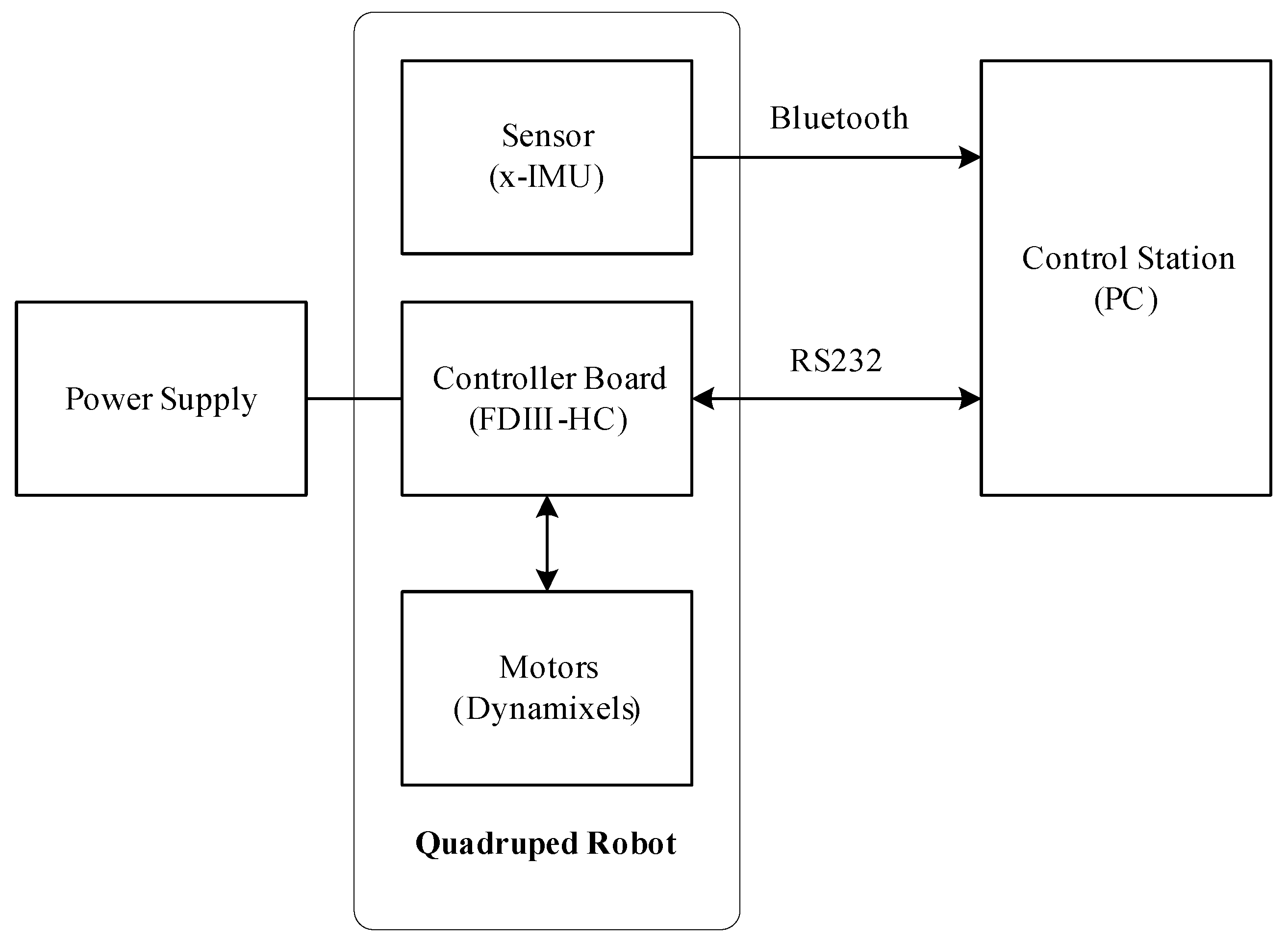
2.1. System Description and Robot Model

In this study, a new quadruped robot is developed to increase the maneuverability of ordinary-legged robots after sustaining damage. Recently, several self-recovery algorithms have been investigated successfully and implemented in robots with at least six legs. However, in most of the test cases, a maximum of two legs lost was considered, meaning that the robots still had four legs to perform any movement. By contrast, in this study, we focus on robots that have a fewer legs to begin with. Figure 2 shows the quadruped robot model considered in this study. The quadruped robot developed herein has four legs and each leg contains three links, which means that the robot has 12-DOFs.

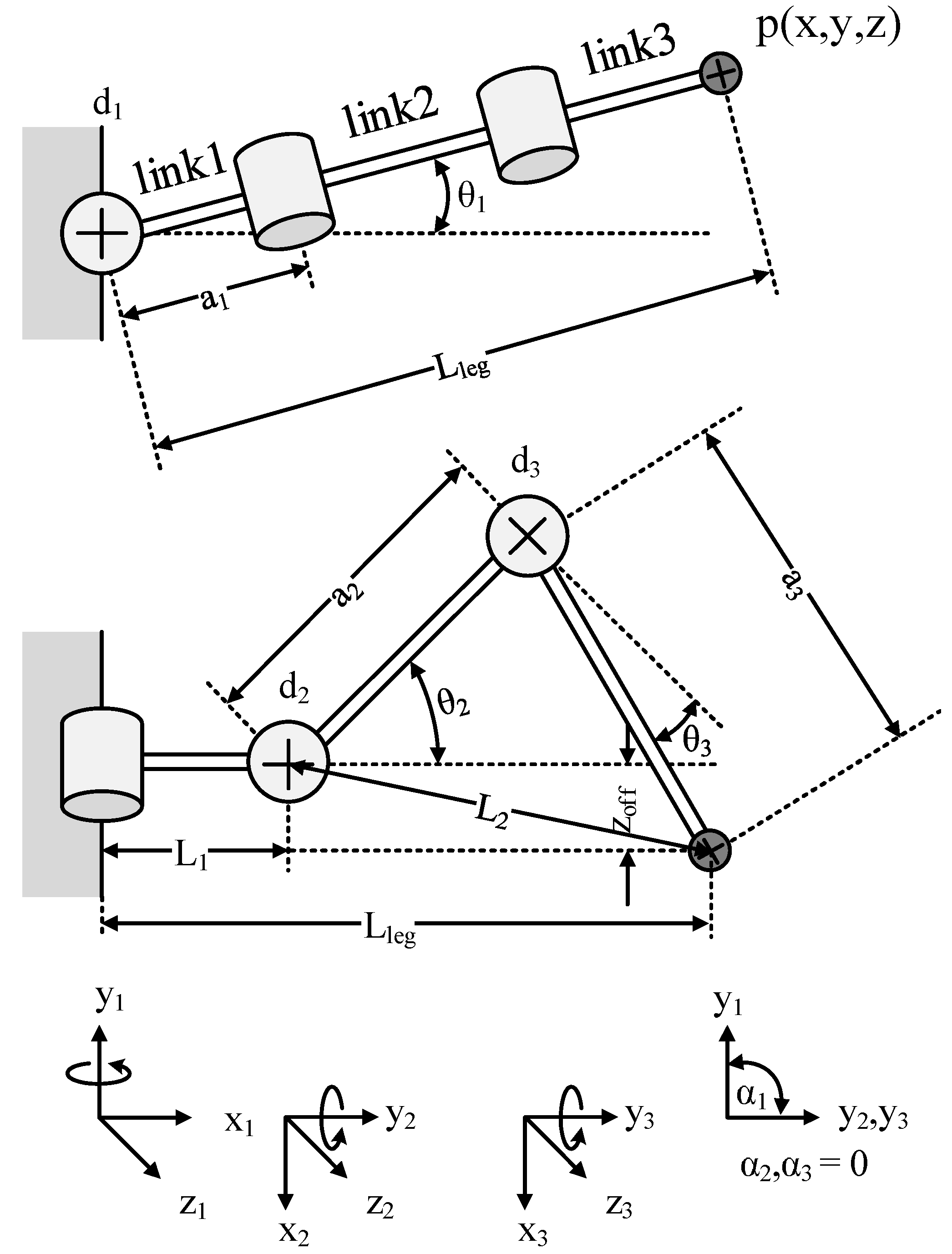
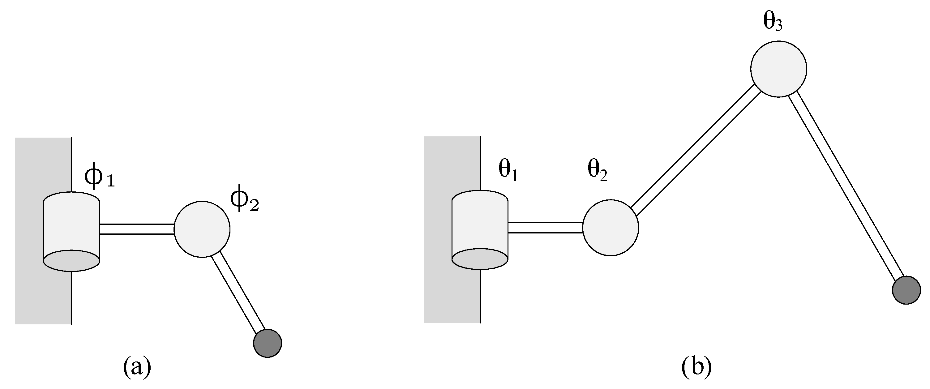
2.1.1. Forward Kinematics of Robot Legs

The forward kinematics of robot legs was analyzed using Denavit–Hartenberg parameters (also called DH parameters) [14], which are used widely for describing robotic systems and other mechanical problems [15]. In the set of DH parameters, four parameters are defined as transformation parameters, namely, d i , θ i , a i , and α i . The notation of each of the parameter can be described as follows [16]:
  • d i (joint displacement):length between the two joints.
  • θ i (joint angle): angle measured between the orthogonal of the common normals. This parameter is variable for revolute joint while the other parameters remain constant.
  • a i (link length): mathematical link length (distance between common normals).
  • α i (link twist): angle measured between the orthogonal of the joint axes. For a prismatic joint, the other parameters are fixed, but this parameter is variable.
The top and side views of the geometrical model of the robot’s leg are shown in Figure 3. Moreover, the link coordinate frame is illustrated herein. As aforementioned, each leg comprises three links, namely, link1, link2, and link3. Joint 1 rotates in the horizontal direction, and joints 2 and 3 move the leg upward and downward along the vertical direction. The joint angles θ 1 , θ 2 , and θ 3 are the angles of link1, link2, and link3, respectively. According to the parameters shown in Figure 3, we can define the DH parameters of the systems as summarized in Table 1.
Position of the robot leg end-effector can be written as follows:
x = a 3 · cos ( θ 1 ) cos ( θ 2 + θ 3 ) + a 2 · cos ( θ 1 ) cos ( θ 2 ) + a 1 · cos ( θ 1 ) ,
y = a 3 · sin ( θ 1 ) cos ( θ 2 + θ 3 ) + a 2 · sin ( θ 1 ) cos ( θ 2 ) + a 1 · sin ( θ 1 ) ,
z = a 3 · sin ( θ 2 + θ 3 ) + a 2 · sin ( θ 3 ) .

2.1.2. Inverse Kinematics of Robot Legs

Forward kinematics, which is used to transform joint information into end-effector position, is explained in the previous subsection. Here, we explain how to control the joint angles of a robot leg to achieve the desired goal. In robotics and animation, this method is generally called “inverse kinematic”. Several methods to obtain the inverse kinematics of a system are available, such as numerical calculation, Jacobian transpose method, and geometric approach. In this study, the geometric approach is used to solve the inverse kinematic because the robot leg has only 3-DOFs. As shown in Figure 3, we have L l e g , L 1 , and L 2 as follows:
L l e g = x 2 + y 2 ,
L 1 = a 1 · cos ( θ 1 ) ,
L 2 = ( L l e g L 1 ) 2 + Z o f f 2 ,
and the angles of the joints can be described as
θ 1 = tan 1 y x ,
θ 2 = tan 1 L l e g L 1 Z o f f + tan 1 1 A 2 A 90 ,
θ 3 = 90 tan 1 1 B 2 B ,
where A and B are a 2 2 + L 2 2 a 3 2 2 · a 2 · L 2 and a 2 2 L 2 2 + a 3 2 2 · a 2 · a 3 , respectively.

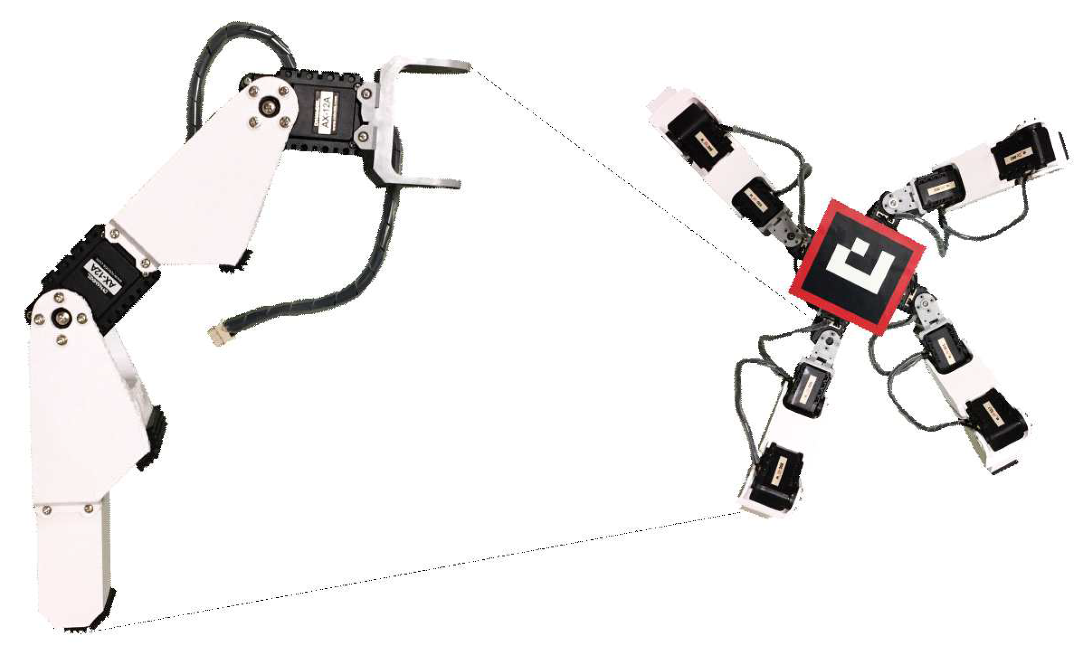
2.1.3. Robot Components

The design of the quadruped robot is geared towards the concept of modularity so that the robot can be assembled easily. The proposed robotic platform comprises of five main components, namely, actuator, controller board, power supply, sensor, and control station. Figure 4 shows the block diagram of the overall system and the details of the connections among the components. Three components are mounted on the robot body, namely, the motors, inertial measurement unit (IMU), and controller board.
In this study, we used 3D printed parts for fabrication and making the robot allowing for faster prototyping and design changes. The final design was later fabricated using higher grade materials. The ABS filament was employed as the material supply in the 3D printer owning to its favorable characteristics. It is beneficial for the components that will be assembled together. Moreover, the original parts provided by Robotis™ company are integrated on the robot body.

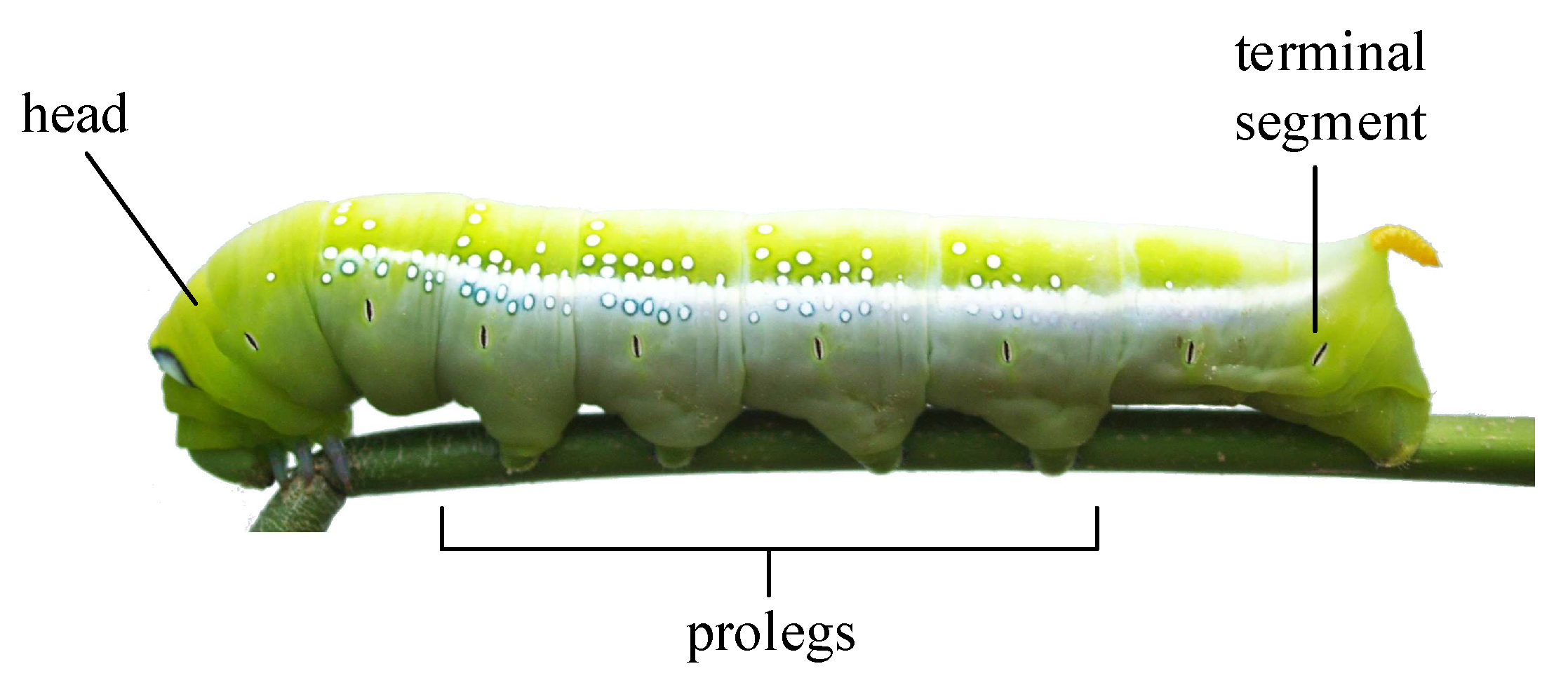
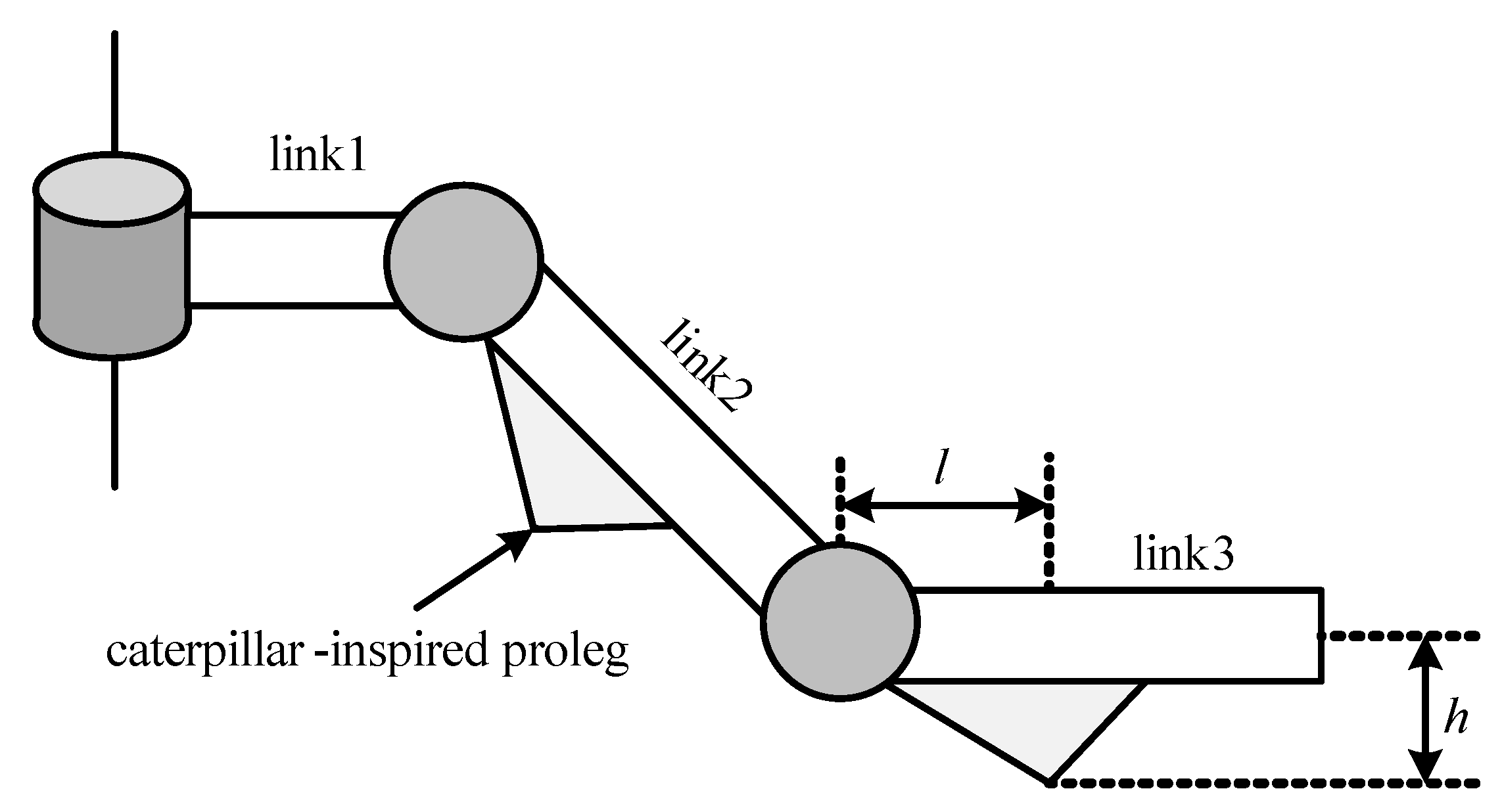
2.2. Caterpillar-Inspired Structure

In nature, an animal can adapt itself extraordinarily for survival. Flexibility is the main key to survival and reproduction. We believe that a bio-inspired robot mechanism would be more robust. According to Trimmer et al. [17], caterpillars are excellent at climbing with their body and prolegs, and they can achieve fault-tolerant maneuverability. As a result, caterpillar-inspired robots have been researched and developed for use in many applications, for instance, wall-climbing [18]. Because the prolegs and body movements can be used to achieve forward propulsion, this concept is applied to help a quadruped robot move by using only one leg in the case of damage. In this study, the design of the CIQR is based mainly on the structure of a caterpillar’s prolegs. Each robot limb is designed to have triangular shape to imitate the caterpillar’s prolegs. The proleg mounted on the robot leg will increase the number of contact points between the robot and environment. Hence, the movement of robot becomes more flexible such that the robot can use prolegs or end-effector for locomotion. The parameter l is the distance from the beginning of the limb to the foot of the altitude, and h is the altitude (height) of the triangle. The quadruped robot used in this study has 3-DOFs per leg. Additionally, the prolegs are added only on the upper and lower limbs, as shown in Figure 5. The reason for using triangular prolegs is to ensure smooth robot motion.

2.3. Optimization of Robot Structure

To ensure that the CIQR can perform well with both normal quadruped gait and caterpillar-inspired crawling gait, the robot structure was optimized by operating with two types of locomotion. The first type of locomotion is trotting gait to control the robot because it is the fastest gait as reported by Darici et. al. in [19]. Two pairs of diagonal legs are moved back and forth between two states, as shown in Figure 6. For the second type of locomotion, a sinusoidal generator is used to produce the rhythmic motion of caterpillar-like locomotion (crawling gait). This method can ensure smooth motion and easy control over the motion [20]. The joint rotating angle can be calculated as follows:
y i = A m p i sin ( 2 π T t + ϕ i ) + O i ,
where y i is the rotation angle of joint i, A m p i the amplitude, T the control period, t the time, ϕ i the phase, and O i the initial offset. Because the limb of robot is designed to be united, two parameters must be optimized, as expressed by Equation (11),
P = l , h ,
where l and h are the parameters of the prolegs of link2 and link3, as illustrated in Figure 5. The quadruped robot is programmed to execute the crawling and the trotting gaits to ensure that the designed model can move properly when crawling using one leg and when performing the normal quadruped gait. Therefore, the fitness function is set as the traveling distance, as follows:
D = μ 1 · d c + μ 2 · d t ,
where μ 1 and μ 2 are weight parameters and d c and d t are the distance traveled by robot with caterpillar-crawling and trotting gait, respectively.

3. Self-Recovery Method

3.1. Conventional Self-Recovery Method

We adopted a modified version of the work described in [8,9]. PSO was employed over GA due to its simplistic modeling and optimization convergence. The method can be described into three main parts, namely, movement sequence coding, objective function, and evolutionary process.

3.1.1. Movement Sequence Coding

As aforementioned, we employed smart electric actuators, Dynamixel™(ROBOTIS, Seoul, Korea), to control the joints to the programmed angles. The PSO particles were designed based on the idea of sequence actions. Each motor is required to perform five sequential actions. The robot performs each action for t seconds ( t = 0.2 ). Every joint is driven by a self-desired action at the same time. Hence, we can define the actions of each motor as follows:
S i = A n g i 1 , A n g i 2 , , A n g i 5 ,
where S is the sequence of actions, i the number id of joint motor, and A n g the control motor angle. Then, the PSO particles (P) can be described using Equation (14):
P = S 1 , S 2 , , S N ,
where N is the number of joints of the legged robot. The proposed robot has 12-DOFs so N is equal to 12. The overall parameters of one particle are 5 × 12 = 60 values. An example of robot movement is shown in Figure 7. The robot performs five actions iteratively until it completes the desired task.

3.1.2. Objective Function

The criteria to achieve the recovery movement of a damaged robot can be set in a form of an objective function. This function is used to judge which solutions can provide the best result. To overcome damage, movability is the main objective of the recovery process. If the robot cannot move properly, it will be impossible to fix the robot. By contrast, if the robot can move to the desired position, we can repair the broken parts of the robot and can send it back to complete its mission. Accordingly, we set movability as the travel distance in a given direction. The damaged robot that can move faster to the required position is said to have the maximum of movability. The distance traveled by the robot can be calculated after the robot moves for T seconds. Figure 8 shows the performance of the broken robot traveling from the original position to the final position. The distance traveled D can be determined using a basic geometrical approach as follows:
D = ( x f x o ) 2 + ( y f y o ) 2 ,
where x o and x f are the position of the robot along the x-axis of the original and the final position, respectively. In addition, y o and y f are the robot position along the y-axis of the original and the final positions, respectively. To follow the required direction, the parameter θ f is put mathematically in the objective function F to decrease its value in case if the robot travels the wrong distance. In addition, we focus on straight line motion in this study. If θ f becomes 0, it means that the robot has traveled straight and F is maximized:
F = e θ f 2 · D ,
where θ f denotes the different angles between the original and the final positions. Moreover, the calculated value of F is used to process the evolutionary method.

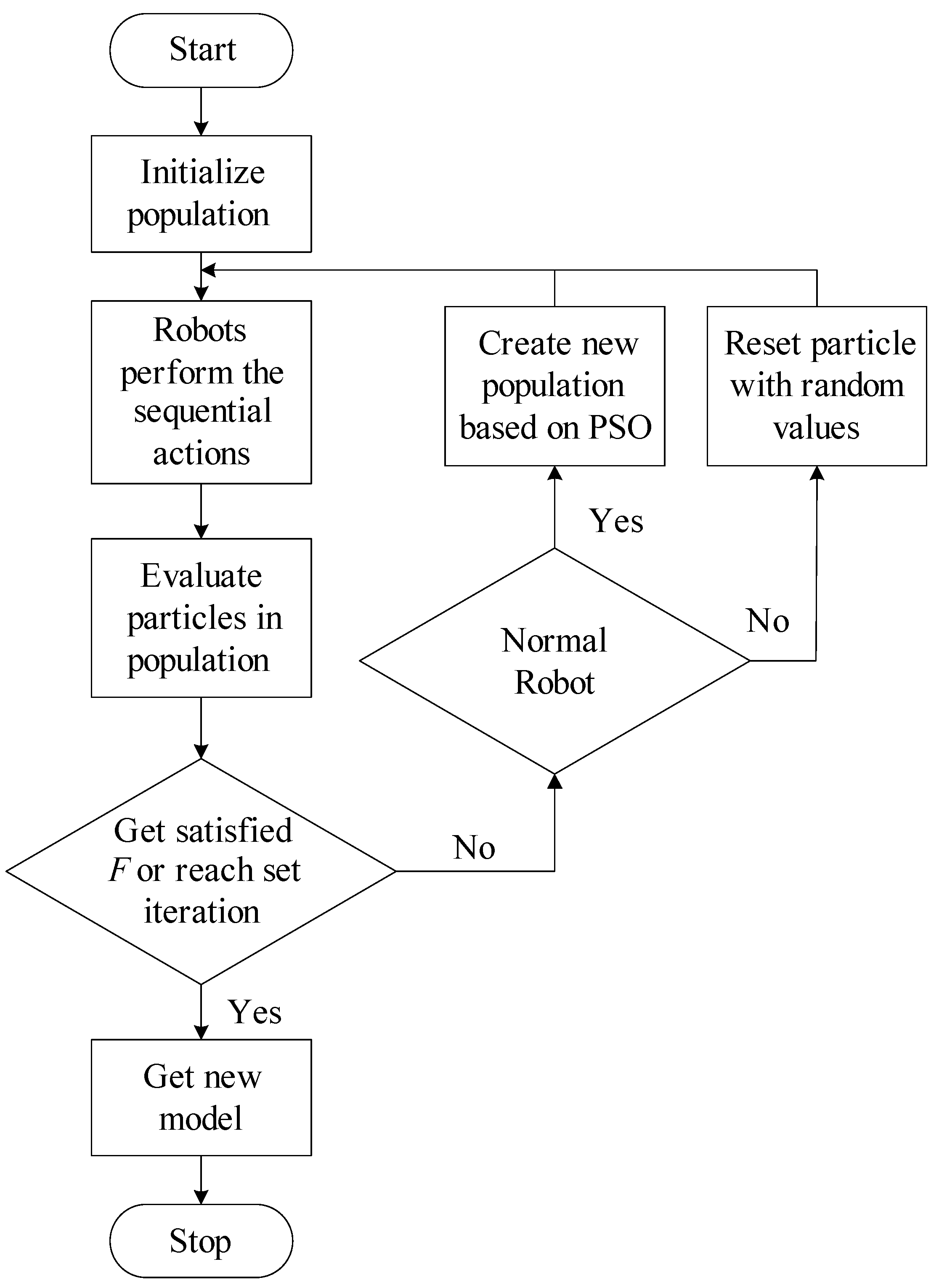
3.1.3. Evolutionary Process

The evolutionary process is similar to the PSO process, as discussed in the previous sections. A flowchart of the overall process is shown in Figure 9. The process starts with the generation of random populations of n particles (P). Thereafter, all particles execute the actions for time T. Next, the performance of each particle is judged based on the value of the objective function F. The evolutionary method is executed under the following conditions:
  • Normal: If a particle is allocated to this state, the action parameter will be updated according to the PSO rule.
  • Capsizing: In practice, the robot attitude should be considered because sensors and loads, e.g., camera, are generally integrated on top of the robot. If the robot flips over during recovery, the sensor or loads may break. Therefore, the particles that cause the robot to flip over should reset all of their parameters randomly.
  • Moving Backward: If the particles cause the robot to move backwards, their parameters should be set as random values, likewise.
  • Mutant: Given the probability p r o b < 0.2 , a few particles should be mutated to avoid the local maximum.
The process will be terminated if the objective function reaches the desired value or if the generation reaches the set value.

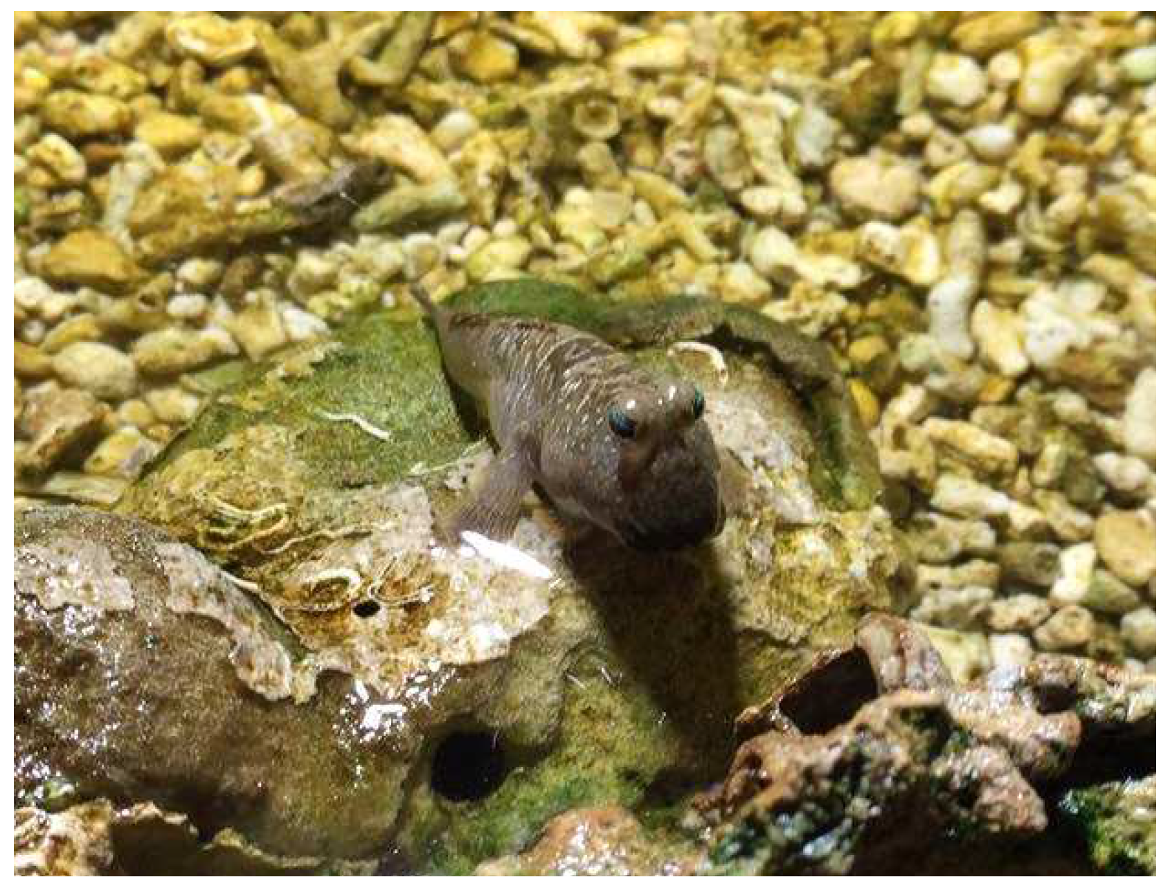
3.2. Mudskipper-Inspired Behavior

Because a quadruped robot needs at least three legs to balance its body [19], it is not feasible for the robot to execute movements after it is damaged. In the existing recovery methods, robots cannot walk properly even if one leg has minor damage. As a result, we investigated an alternative method to control the robot based on specific actions. Because such actions can be designed manually based on careful observation, it can be guaranteed that the robot will maintain a good posture at all times. To decide what actions to perform, we consider the motion of a fish called “mudskipper”, as shown in Figure 10. Mudskippers are amphibious fish, which means that they can use pectroral fins to “walk” on land. We mimicked crawling behavior of mudskippers because it activates only two fins and the tail to achieve the excellent locomotion over the different types of terrains [21]. Recently, mudskipper-inspired robots have been developed and analyzed. According to McInroe et al. [22], MuddyBot uses its tail and fins to improve its ability to move. This behavior can possibly be used to help a broken quadruped robot move.

Mudskipper Behavior

In this study, we focus only on the operation of the two fins of a mudskipper. The simplified model of mudskippers fins is defined as a 2-DOF system, containing two revolute joints with respect to the vertical and the horizontal directions. Figure 11a shows the design model of the mudskipper fins. According to the robot model discussed herein, a quadruped robot consists of 3-DOF per each leg as shown in Figure 11b. Then, the angular rotations of θ 2 and θ 3 are set along a reverse direction. Hence, we can describe the setting of each angle as follows: θ 1 = ϕ 1 , θ 2 = ϕ 2 and θ 3 = ϕ 2 . To imitate fin movement, we performed numerical calculation using the sine and cosine functions of time t and one-time-moving period T, as shown below:
ϕ 1 = w m · cos ( 2 π t T ) ,
ϕ 2 = h m · sin ( 2 π t T ) ,
where w m and h m are the width and the height of the moving trajectory, respectively. The moving phase of the leg consists of two different phases, namely, swing and touch. At time t = 0 s, the leg will start from the beginning and cover a circular trajectory, and, at t = T s, the leg will end at the starting point. Note that the swing phase is the action in which the leg lifts off the ground, and the touch phase is the action in which the leg touches the ground.
To control the robot direction, the robot orientation θ r is used as the control parameter to tune the direction of motion. A simple feedback control scheme is used in this case. The corresponding closed-loop control diagram is shown in Figure 12. In this study, the parameter h m is set as a constant because a large change in h m can destabilize the robot’s posture, whereas w m is varied. For example, in case of the loss of two legs, we can adjust the parameter w m of two legs to increase the size of the trajectory loop along the horizontal direction. If the parameters w m are set diversely, the robot can be maneuvered to turn left or right. However, it is difficult to tune the parameters. In the next section, we integrate the mudskipper-inspired movement with reinforcement learning to improve the robot with the flexibility to perform in various scenarios.

3.3. Self-Learning Mudskipper-Inspired Crawling Algorithm (SLMIC)

To enhance the performance of the robot’s mudskipper-inspired movement, the learning approach is integrated to help the robot move in the straight direction. For decades, researchers have made attempts to combine the learning algorithm with robots to improve the flexibility and efficiency of robots. Reinforcement learning have been used in many applications in the field of robotics. In [23], a wheeled robot was programmed to be able to learn online. In addition to high-DOF robots, humanoid robots can learn to walk and crawl successfully by using the methods described in the papers of Lin and Yamaguchi [24,25]. Moreover, the walking speed of quadruped robots can be increased by using the method proposed by Kohl and Stone [26]. Although these reinforcement learning based studies were successful in their own right, a key problem with many of approaches in the literature is the size of the state and action space. Generally, for a multi-joint robot, the state is set as the current position of the joint angles, which means that based on the number of DOFs of the quadruped robot developed, the state would be 12-dimensional. Thus, a new concept of state and action design is proposed in this study.

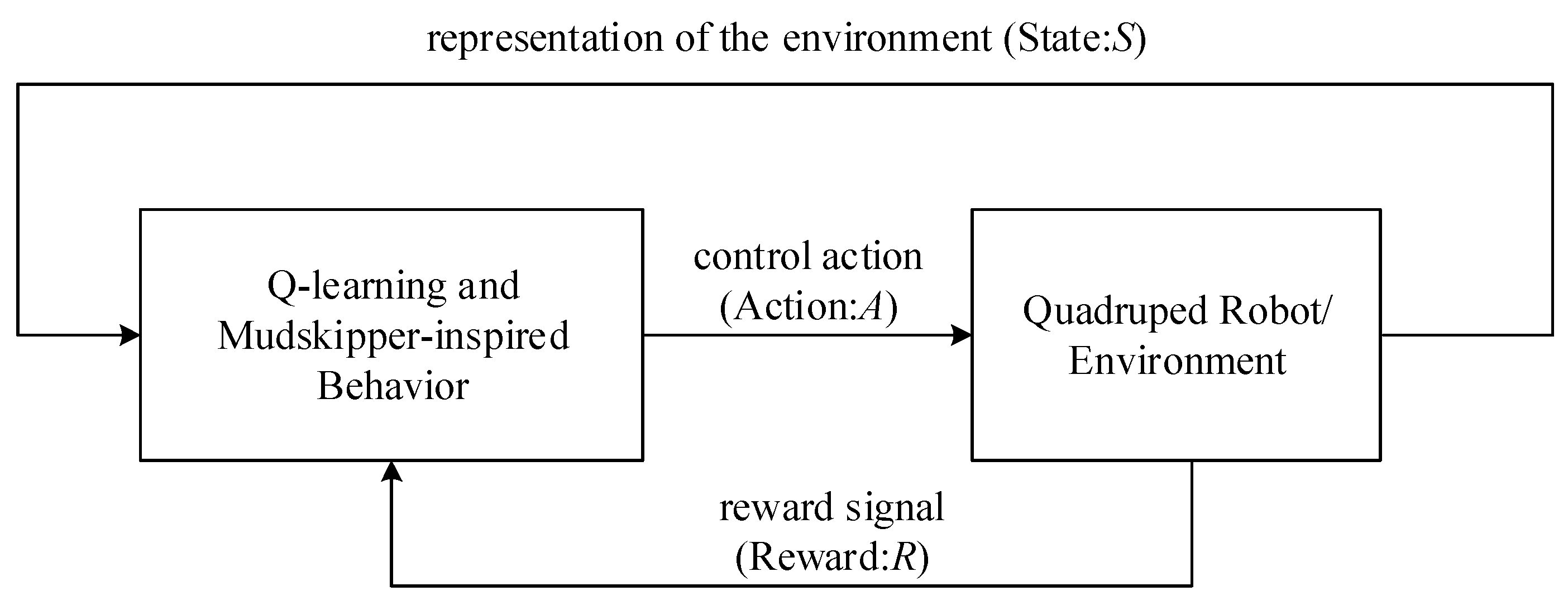
3.3.1. Q-Learning Algorithm

Reinforcement learning can be simply explained as the process of training pets, such as dogs and cats, to perform certain actions. However, this process can be described as a trial-and-error problem as well. In the beginning of a dog’s training process, it seems impossible for a dog to perform a requested task without error. The dog will try to perform some action randomly, such as walking, sitting, or jumping, to get a snack. After it gets the snack, the dog will remember the action that can possibly get it a snack again. By contrast, the dog will not do any action that would lead to an adverse outcome such as a scolding or a beating. Accordingly, the process of reinforcement learning can be thought to be based on reward and punishment. In this study, the quadruped robot is controlled using Q-learning and mudskipper-inspired behavior. The control policy will be adapted with the current state, provided by the surrounding environment, following the Q-learning approach. For example, if the robot is in a state in which it is heading north, but we command it to go to the east, the control policy will be changed to make the robot go to the east. The three main parameters of reinforcement learning are as follows:
  • State (S): It is defined as the current scenario of a system, for instance, the position of the robot.
  • Action (A): In one system, several actions would be required to be conducted in each state. In wheel-based robots, the actions can be moving forward, turning left, and turning right.
  • Reward (R): It depends on the current state and action. It can be positive, negative, or zero for the win, lose, and draw scenarios, respectively. For example, when a robot encounters an obstacle, it needs to avoid the obstacle. If the robot decides to move forward and hit an obstacle, it will get a negative outcome in the form of a punishment. On the contrary, if the robot avoids an obstacle properly, it will receive a positive reward.
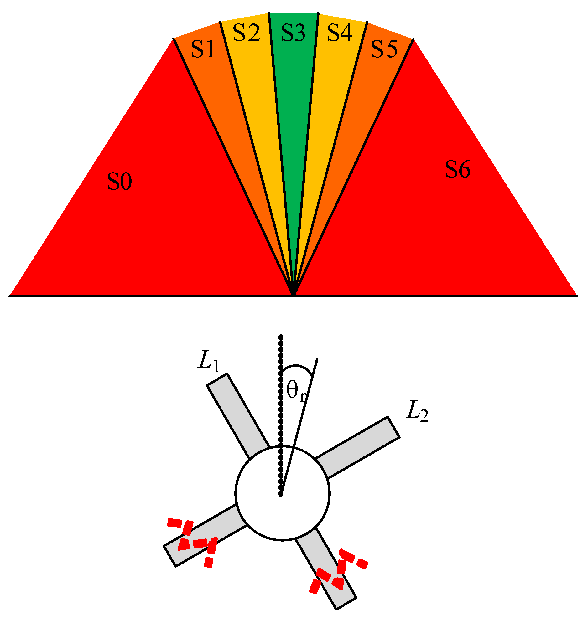
Finally, the objective of learning, which is known as policy ( π ), will be achieved. The best policy is the selection of actions that provide the highest reward, the so-called “Maximum Sum of Expected Rewards”.
Q-learning is a reinforcement learning approach with non-model requirements. It employs the concept of Markov decision process (MDP) with finite state arrays to arrive at the optimal policy [27]. The expected reward will be stored in a d-dimensional state-action array. The number of d can be set manually by the user. Q-learning is one algorithm among the various algorithms associated with the temporal-difference method. The Q-values are acquired as follows:
V * ( s ) = max a Q ( s , a ) .
Because the Q-function does not need a model for learning and selecting actions, no model is required for state transitions. Q is updated by using the new information obtained after performing an action to correct the old policy. The Q-values are updated numerically based on the temporal-difference concept using Equation (20) [28]:
Q ( s , a ) = Q ( s , a ) + α ( R ( s ) + γ max a Q ( s , a ) Q ( s , a ) ) ,
where α and γ are the learning rate and the discount factor, respectively. The procedure of the Q-algorithm is summarized in Table 2. The proposed method employs both Q-learning and mudskipper-inspired behavior to control the damaged robot. The controller structure is illustrated in Figure 13.

3.3.2. State

In spite of using joint angles, we employ robot orientation as the state in the Q-learning. The yaw angle of the robot is divided into seven regions, as shown in Figure 14. The regions that separate the state are listed in Table 3. We select the robot orientations as the state to be able to control robot direction properly, and another advantage of doing so is that a robot can learn other actions simultaneously if provided with another Q-value table.

3.3.3. Action

Because the mudskipper-inspired movement requires only two legs to realize crawling, the number of robot actions is set to 7 for both legs by tuning the parameter w m in Equation (17). The parameters w m 1 and w m 2 are used to control the legs L 1 and L 2 as shown in Figure 14, and w m 1 and w m 2 are calculated using the following equations:
w m 1 = 5 + a 1 ,
w m 2 = 5 + a 2 ,
where a 1 and a 2 are the adjusting parameters, and their values are set as given in Table 4. The numbers used for each action are set unequally to ensure the robot perform different actions, such as turn left and turn right. Therefore, the total number of Q-value is 7 × 7 = 49 , which is smaller than that in the conventional setting.

3.3.4. Reward

Because the aim of the present study is to design a recovery method to ensure that a robot can move after sustaining damage, we set the reward as the summation of two rewards, namely, state reward ( R s ) and action reward ( R a ):
R = R a + R s .
As a result, we can control not only the robot orientation but also the movability, that is, distance traveled. To facilitate robot motion in straight line, the state reward was designed to be the values listed in Table 3. The robot gets the negative reward (punishment) if it turns left or right. This ensures that, after leaning, the robot moves in the desired direction. Furthermore, the action reward is used to propel the robot to move forward faster, as expressed by Equation (24). If the robot moves backward, it will be punished with −10 reward. By contrast, if the robot can move the longest distance, it will receive +10 reward.
R a = 10 if   max   distance , d 10 if   moving   backward ,
where d is the distance traveled by the robot.

4. Results and Discussion

In this study, two major experiments were conducted in a simulation environment and with a real robot to evaluate the performance and improvement of the proposed robot structural design and the recovery method. In addition, several sub-experiments were conducted to test the proposed robot and recovery method in different scenarios. It starts with the first part of the experiments that pertains to testing the design of the novel quadruped robot structure with caterpillar-inspired prolegs. The performances of the self-learning mudskipper-inspired crawling algorithm (SLMIC) is judged thereafter.

4.1. Results of Caterpillar-Inspired Quadruped Robot (CIQR)

To achieve the designed upright structure, the shape of the legs of CIQR was optimized by numerical simulation as mentioned in the first part of this experiment. Thereafter, the advantages of a new designed structure were analyzed by conducting two sub-experiments, namely, recovering a robot by using conventional recovery methods in a simulation and operating the proposed robot with caterpillar behavior in a real application. Note that, in both sub-experiments, the common structure and the proposed CIQR structure were compared.

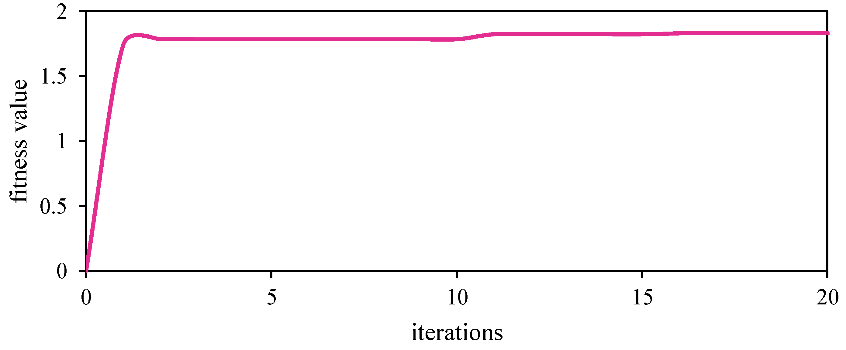
4.1.1. Optimization of Robotic Structure

The simulation was run for 20 iterations with μ 1 and μ 2 as 0.5. The weight parameters were set to equal values because the CIQR is required to assign equal weights to both actions. Figure 15 shows the fitness values of optimization with time, and it illustrates that the robot can discover a new structure that can help it walk longer. The evolution of the robot leg can be seen in Table 5. At the beginning, the high prolegs cause the robot to walk slowly in accordance with the fitness values shown in Figure 4. After five iterations, the robot evolves to being suitable for crawling and trotting, such that the robot structure changes, and the fitness value is increased. In iteration = 20, the robot structure changes slightly. A comparison between the proposed model and the conventional model was made in this study. The results show that the optimized model can travel 39.19 cm and 13.34 cm in the trotting and crawling gaits, respectively. By contract, the normal structure can move 36.78 cm and 13.83 cm in the trotting and crawling gaits, respectively. Figure 16 shows the actual CIQR model fabricated using a 3D printer.

4.1.2. Simulation Experiments of CIQR with Conventional Recovery Methods

In the experiment, the damage recovery algorithm was employed to compare the performance of the normal design (quadruped robot without prolegs) and the proposed design. The evolutionary adaptive gait, which involves creating sequential actions, was employed in this test; the concept underlying this process was inspired by existing works presented in [8,29]. Three experimental scenarios were tested in this study, namely, one leg loss, two leg loss, and three leg loss, as shown in Figure 17. A simple algorithm was employed to control the damaged robot. For each joint, five rotational angles are controlled in sequences. The robot performed motions step-by-step in round-robin fashion, from the first angle to the last one. Because CIQR has 12 joints, 60 parameters in total are used to control the robot. To determine 60 parameters, PSO was used to execute the discovery process once again [30]. At the beginning, all parameters were set randomly. Next, the robot performed the first action with the first rotational angle of each joint. At t = T , the robot performed the second action. This step was iterated until t reached the setting time. The fitness function of this algorithm was set as the distance that the damaged robot could travel. The test results obtained with the damaged robot are given in Table 6. As can be seen, with only one leg lost, CIQR performed better than the normal robot in terms of the total distance traveled. By contrast, the normal robot produced a good result in the second case as it walk about 10 cm more than the proposed robot. The CIQR moved slower in this case possibly because of the additional weight of the prolegs. In case of only one leg, CIQR could travel longer than the normal robot. However, the control method used in this benchmark could not efficiently control the robot because the robot motion was not smooth, and the possibility of the robot flipping over during the evolutionary process prevailed. These problems were tested once again using the proposed recovery algorithm (i.e., SLMIC) described in Section 3.3.

4.1.3. Experimental Results with Caterpillar-Inspired Crawling Behavior

To ensure that the proposed robot could function in real scenarios, an experiment with the actual robot was conducted. In this case, the performance of CIQR was compared with that of the normal robot. The evaluation was conducted with a damaged robot having one functional leg. As in the simulation, both robots were programed to move forward according to Equation (21) with the same set of parameters, that is, A 2 = A 3 = 40 , ϕ 2 = 0 and ϕ 3 = 30 , which are the amplitudes for controlling link2 and link3, and the initial offsets of link2 and link3, respectively. Link1 was set to the fixed direction of 0 to ensure the robot traveled straight. The results show that both robots could travel straight but shifted slightly towards the right. However, the novel structure of CIQR traveled longer than the normal robot in the simulation, as shown in Figure 18. The normal robot moved forward and stopped after 20 s, traveling 34.17 cm in the course. In the same period, the CIQR traveled 52.08 cm. Additionally, the positions of both robots in the experiment were measured using an overhead camera and image processing technique.

4.2. Evaluation of Self-Learning Mudskipper-Inspired Crawling Method (SLMIC)

In the benchmark, the proposed recovery algorithm was tested in four different scenarios and compared to the conventional evolutionary method without direction (EA), evolutionary method with direction (EAD) and mudskipper-inspired movement (MUD), in the simulation. The test scenarios were as follows:
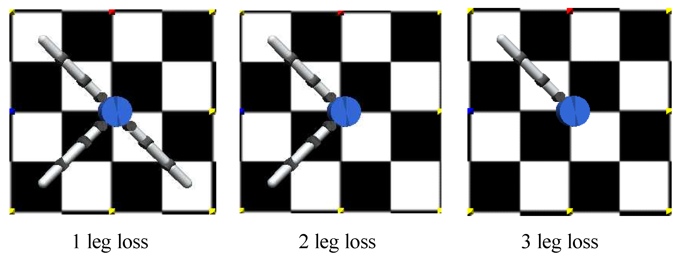
  • case A: one leg lost,
  • case B: two adjacent legs lost,
  • case C: two diagonal legs lost,
  • case D: two adjacent legs and one limb lost.
All the simulation scenarios were run for 20 s with the four methods. After the simulations were executed, only the proposed method, that is, SLMIC, was employed to operate the actual robot because the evolutionary processes were time consuming and SLMIC provided the best performance in terms of recovery distance. The performance of SLMIC was compared with the control method used to control the robot before it was damaged. To achieve the robot position, Inertial Measurement Unit (IMU) was incorporated into the robot and was used to measure the short distance that was required in the recovery process. Image processing was additionally used to obtain the distance traveled by the robot for reporting purposes.

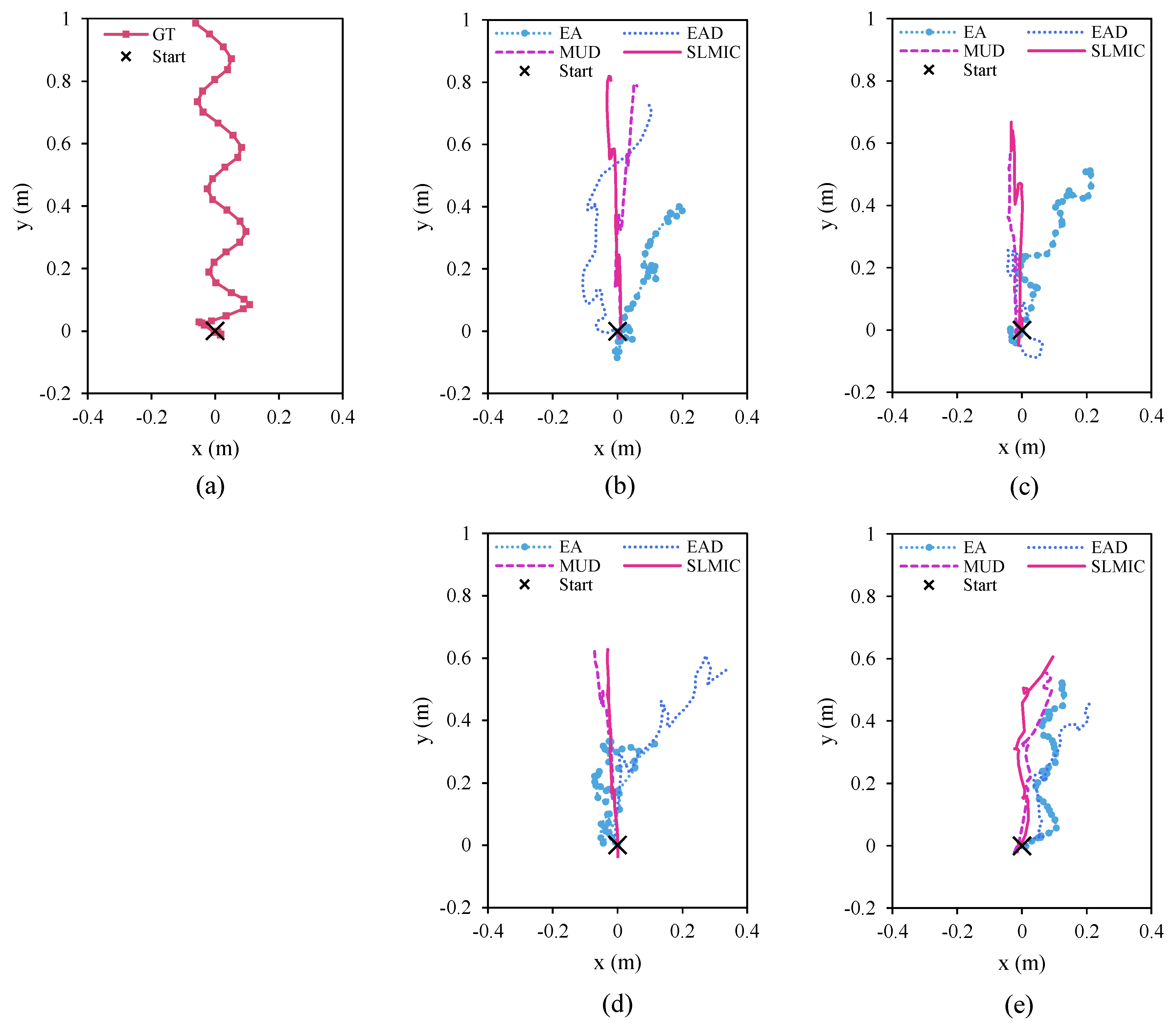
4.2.1. Simulation Results of SLMIC Vis-à-Vis Other Methods

The numerical simulation was conducted separately for each case in the experiments. As shown in Figure 19, the results of four different damage scenarios are as follows:
  • case A: The results show that all methods used in the simulation allowed the robot to be able to move again. With one leg lost, it was easy for the robot to travel with three functional legs. However, not all methods provided the acceptable results. EA helps the robot move the shortest distance compared with other methods, as shown in Figure 19b. EAD helps the robot move longer than EA but it lost out to the MUD and SLMIC methods. By employing the specific actions of mudskippers, both MUD and SLMIC help the robot travel longer distances. However, SLMIC provided the best result in this test because it helped the robot learn to move forward faster.
  • case B: The robot programmed using EA traveled faster than the robot programmed using EAD, as shown in Figure 19c. However, EAD provided the better result in terms of direction. It seemed that, with EAD, the robot optimized multiple objectives, namely, distance traveled and direction of travel. As a result, the robot assigned more importance to direction in optimization, which reduced the distance traveled. MUD and SLMIC provided decent results in terms of distance traveled and direction of travel. Once again, SLMIC provided the best performance.
  • case C: Similar to the two cases in the experiments, with MUD and SLMIC, the robot covered longer distances. However, SLMIC performed better in terms of direction of travel. Opposite to case B, EAD could deal with only the distance traveled. At this time, EAD attempted to optimize the distance traveled by the robot, but it failed to optimize the direction of travel, and thus the robot failed to move straight ahead. With EA, the robot could not perform well because the two diagonal legs affected its balance. The robot flipped over during the recovery process which limited its ability to move. As a result, the robot programmed using EA could travel properly, as shown in Figure 19d.
  • case D: This experiment was the most challenging because of the limited number of functional legs and actuators, as shown in the results in Figure 19e. Given the extremities, the robot programmed using SLMIC could learn to recovery itself with SLMIC and provided the best results in terms of direction and distance. MUD with its specific control method was the second best performer in this experiment. EAD exhibited the worst performance owning to the same reason as in case B, and EA achieved a fair level of performance.
From the results, it can be concluded that the proposed method (SLMIC) can provide the best results compared to the other methods in terms of direction of travel and the distance traveled. However, a certain learning time is required to achieve the goal. The performance of MUD was inferior to that of SLMIC, but, in most cases, it performed satisfactorily. However, the crucial aspect of MUD is that it employs specific mudskipper-inspired actions with no time required for evolutionary process or learning. The results indicate that it would be difficult to guarantee satisfactory performance in terms of direction and distance traveled with both EA and EAD because differences in robot model can cause task failures, and the methods can get stuck in local minima when performing multi-objectives optimization, which can lead to failure.

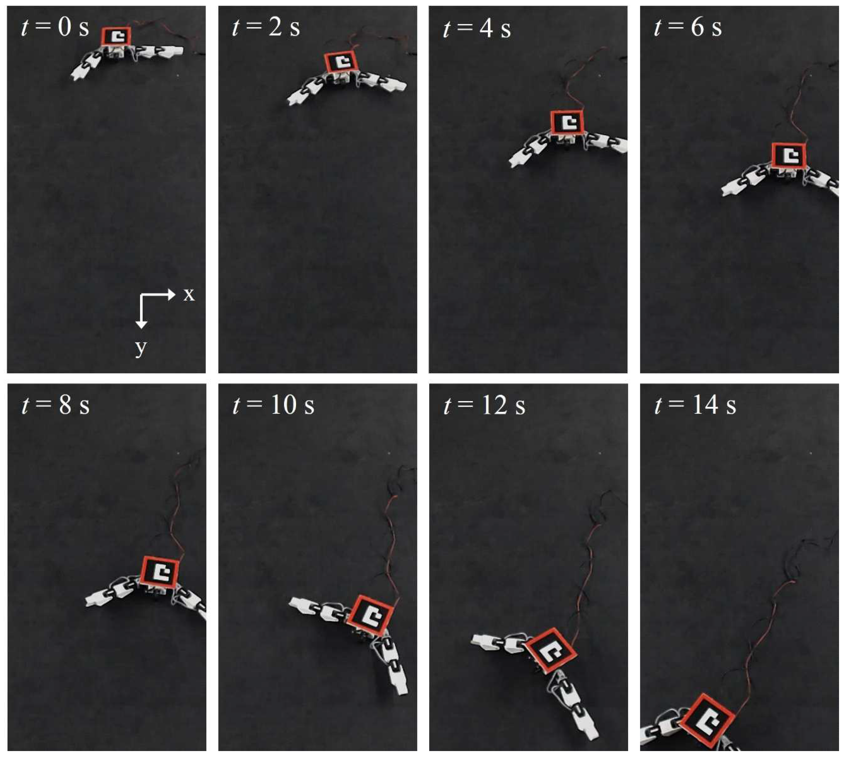
4.2.2. Comparison of Experimental Results Obtained Using Previous Control Method and SLMIC

Because SLMIC exhibited the best performance in the simulation, we decided to conduct the experiment involving the actual robot using only with SLMIC. We compared the performance of SLMIC with the previous controller, that is, trotting gait (TG). The test cases were the same as those in the experiments conducted in Section 4.2.1.
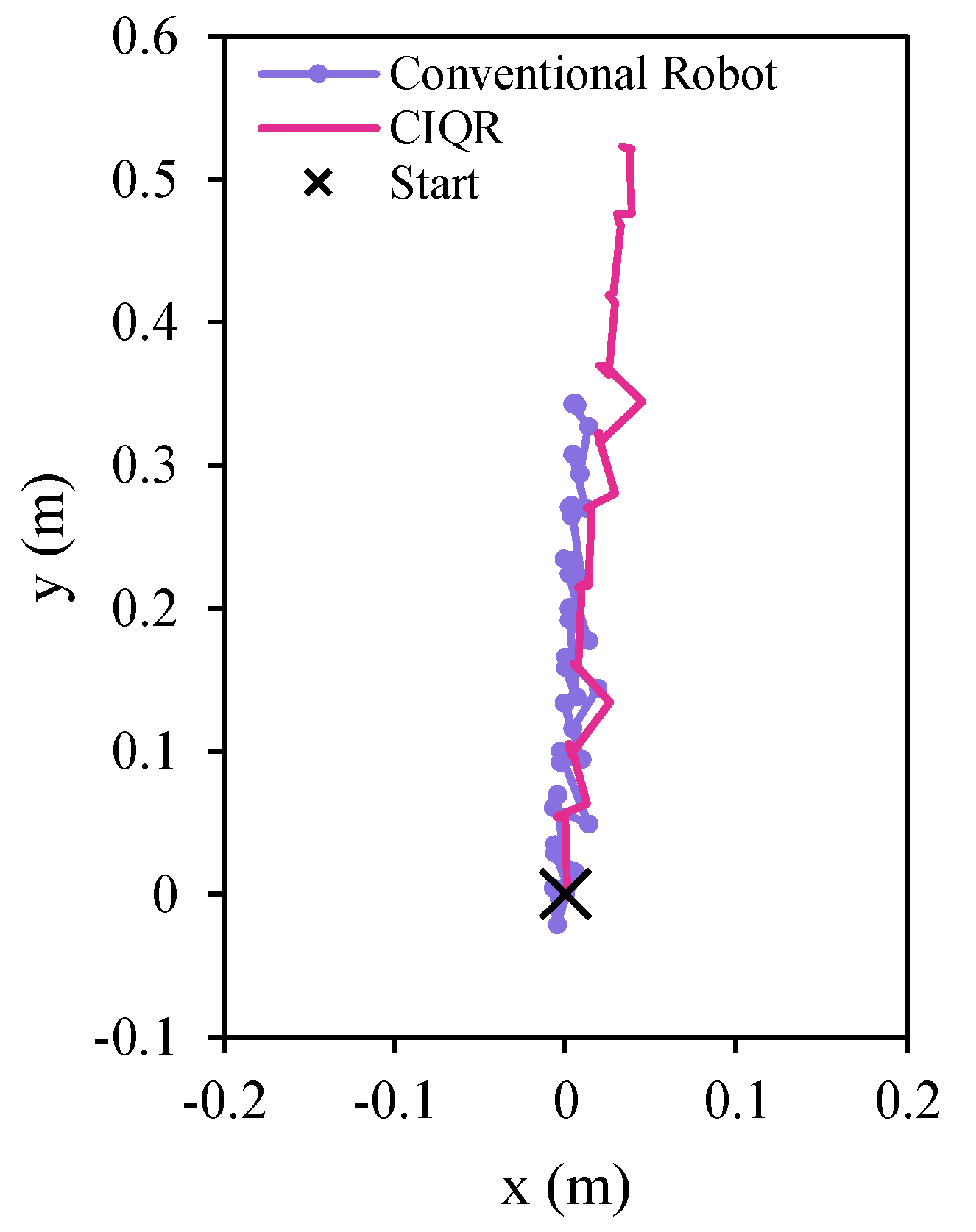
  • case A: The results of this test case clearly show that with SLMIC the robot could recover itself to reach the goal, as shown in Figure 20b. Compared to the ground truth (in Figure 20a), the robot programmed with SLMIC almost traveled the same distance as the healthy robot. By contrast, the robot could not move well when the previous control method (trotting gait controller) was employed. It caused the robot to move back and fourth around a single point in a certain working area.
  • case B: In this case, SLMIC with the damaged robot achieved the same result as the healthy robot. However, the robot moved slightly towards the right part of the working space. By contrast, the robot with two adjacent legs-lost and programmed by the previous method could not perform well, traveling only around the starting point, as shown in Figure 20c.
  • case C: As shown in Figure 20d, with the trotting gait, the broken robot could not function properly and moved backwards during the experiment. This can be one of the reasons why the recovery method is significant for multiple-legged robots. By contrast, the proposed method provided good performance with the learning process. According to the trajectory traveled by the robot programmed with the proposed method, it moved towards the right at the beginning, but it returned to the predetermined direction with the passage of time.
  • case D: Similar to results of the simulation in the previous section, the robot with two adjacent legs and one limb lost found it difficult to achieve the same performance as the healthy robot. However, SLMIC made a big difference compared to the previous controller. Even so, it could not help the robot recover fully, but it did help the damaged robot cover more than half the distance covered by the healthy robot.
After the experiments with actual robots were conducted properly, it was found that the damaged robot could practically not move when the previous controller (trotting gait in this case) was used. As a result, the recovery method that can provide an alternative solution for damaged robots is needed. With SLMIC, the proposed recovery method based on specific actions that guarantee adaptable movement owning to learning could solve most of the problems successfully, and, in one special difficult case, it recovered by approximately 50 percent. The example of robot actions with SLMIC in Figure 21 (case C) shows that the robot turned slightly to the wrong direction at the beginning, but it recovered and moved along the correct direction at the end. Finally, the experiments confirmed that the proposed method (SLMIC) is suitable for quadruped robots with a limited number of functional legs.

5. Conclusions

In this paper, a novel structure model of the quadruped robot and self-recovery method were proposed. The CIQR was developed to imitate the crawling locomotion of the caterpillar for the case in which the robot has a small number of active legs. Prolegs similar to those on a caterpillar were added onto the robot limb to improve its ability to move after some parts of the robot were damaged. The proposed bio-inspired quadruped robot structure was optimized to ensure that it can operate in both normal and abnormal scenario, and PSO was used as the optimization method. Moreover, a new bio-inspired locomotion method based on the movement of mudskipper in nature, called SLMIC, was proposed in this paper. The reinforcement learning method, Q-learning, was integrated to improve locomotion adaptability. The specific actions inspired by mudskippers were set as an action for Q-learning processes. The orientation of the robot body was sent to the learning process as a state (current scenario of the robot). The positive and negative rewards were given to the robot when it performed the task. The robot received a positive reward when it moved forward in a straight direction. On the other hand, it received a negative reward when it moved backward.
The results confirm that the proposed structure with prolegs provided better results compared to a normal structure when the robot legs were damaged, especially when the robot had only one leg. With one functional leg, the robot with the proposed structure could travel almost eight times longer than the robot without prolegs. According to the numerical simulation and experiments, the recovery methods are feasible for implementation in a damaged robot that has at least one leg. From the simulation, the robot programmed with SLMIC provided a straighter and longer path than the robot performed with other methods. During the experiment, it was found that the damaged robot controlled with SLMIC could travel in a straight path longer than the robot without recovery methods. The most interesting finding is that, with carefully designed actions, which are based on the simple behaviors of mudskipper, a robot can learn new habits to achieve the same goal as a healthy robot. In the future, it is planned to apply and to develop the proposed structure and self-recovery method with other legged robots to improve the performance.

Author Contributions

S.C. and Y.K. designed the study and conceived of the presented idea; S.C. carried out the simulation and experiments; S.C. took the lead in writing the manuscript. Y.K., T.E., and A.A.R. helped to supervise the study and reviewed the paper.

Acknowledgments

This work is supported by MEXT (the Ministry of Education, Culture, Sports, Science and Technology), Japan.

Conflicts of Interest

The authors declare no conflict of interest.

Abbreviations

The following abbreviations are used in this manuscript:
DOFsDegrees of Freedom
GAGenetic Algorithm
PSOParticle Swarm Optimization
DHDenavit–Hartenberg
CIQRCaterpillar-Inspired Quadruped Robot
EAEvolutionary Algorithm
EADEvolutionary Algorithm with Direction
MUDMudskipper-Inspired Movement
SLMICSelf-Learning Mudskipper-Inspired Crawling
TGCTrotting Gait Controller

References

  1. González-de Santos, P.; Garcia, E.; Estremera, J. Quadrupedal Locomotion: An Introduction to the Control of Four-Legged Robots; Springer: Berlin/Heidelberg, Germany, 2006. [Google Scholar]
  2. Liu, M.; Li, M.; Pang, J. Fault-tolerant gait implementation of hexapod robot based on finite state automata. In Proceedings of the 2017 29th Chinese Control And Decision Conference (CCDC), Chongqing, China, 28–30 May 2017; pp. 6800–6805. [Google Scholar]
  3. Gao, Z.; Ma, L.; Wang, J. Fault tolerant control method for displacement sensor fault of wheel-legged robot based on deep learning. In Proceedings of the 2018 WRC Symposium on Advanced Robotics and Automation (WRC SARA), Beijing, China, 16 August 2018; pp. 147–152. [Google Scholar]
  4. Dubrova, E. Fault-Tolerant Design; Springer Publishing Company: Berlin/Heidelberg, Germany, 2013. [Google Scholar]
  5. Yang, J.M.; Park, Y.K.; Kim, J.G. Fault-Tolerant Gait Planning of Multi-Legged Robots. In Mobile Robotics, Moving Intelligence; Buchli, J., Ed.; IntechOpen: Rijeka, Croatia, 2006; Chapter 28. [Google Scholar] [Green Version]
  6. Murakami, M. Task-based Dynamic Fault Tolerance for Humanoid Robots. In Proceedings of the 2006 IEEE International Conference on Systems, Man and Cybernetics, Taipei, Taiwan, 8–11 October 2006; Volume 3, pp. 2197–2202. [Google Scholar]
  7. Bongard, J.; Zykov, V.; Lipson, H. Resilient Machines Through Continuous Self-Modeling. Science 2006, 314, 1118–1121. [Google Scholar] [CrossRef] [PubMed]
  8. Qiu, G.Y.; Wu, S.H. The Evolutionary Locomotion of Tripedal and Quadrupedal Biomorphic Robots. In Proceedings of the 2011 International Conference on Technologies and Applications of Artificial Intelligence, Las Vegas, NV, USA, 18–21 July 2011; pp. 45–50. [Google Scholar]
  9. Liang, J.; Xue, C. Self identification and control of four-leg robot based on biological evolutionary mechanisms. In Proceedings of the 2010 5th IEEE Conference on Industrial Electronics and Applications, Taichung, Taiwan, 15–17 June 2010; pp. 958–961. [Google Scholar]
  10. Koos, S.; Cully, A.; Mouret, J.B. Fast damage recovery in robotics with the T-resilience algorithm. Int. J. Robot. Res. 2013, 32, 1700–1723. [Google Scholar] [CrossRef] [Green Version]
  11. Cully, A.; Clune, J.; Tarapore, D.; Mouret, J.B. Robots that can adapt like animals. Nature 2015, 512, 503–507. [Google Scholar] [CrossRef] [PubMed]
  12. Ren, G.; Chen, W.; Dasgupta, S.; Kolodziejski, C.; Wörgötter, F.; Manoonpong, P. Multiple chaotic central pattern generators with learning for legged locomotion and malfunction compensation. Inf. Sci. 2015, 294, 666–682. [Google Scholar] [CrossRef] [Green Version]
  13. Zhang, T.; Zhang, W.; Gupta, M.M. Resilient Robots: Concept, Review, and Future Directions. Robotics 2017, 6. [Google Scholar] [CrossRef]
  14. Geva, Y.; Shapiro, A. A Novel Design of a Quadruped Robot for Research Purposes. Int. J. Adv. Robot. Syst. 2014, 11, 95. [Google Scholar] [CrossRef] [Green Version]
  15. Atique, M.M.U.; Ahad, M.A.R. Inverse Kinematics solution for a 3DOF robotic structure using Denavit–Hartenberg Convention. In Proceedings of the 2014 International Conference on Informatics, Electronics Vision (ICIEV), Dhaka, Bangladesh, 23–24 May 2014; pp. 1–5. [Google Scholar]
  16. Spong, M.; Hutchinson, S.; Vidyasagar, M. Robot Modeling and Control; Wiley: New York, NY, USA, 2005. [Google Scholar]
  17. Trimmer, B.A.; Takesian, A.E.; Sweet, B.M.; Rogers, C.B.; Hake, D.C.; Rogers, D.J. Caterpillar locomotion: A new model for soft- bodied climbing and burrowing robots. In Proceedings of the 7th International Symposium on Technology and the Mine Problem, Monterey, CA, USA, 2–5 May 2006. [Google Scholar]
  18. Wei, W.; Dawei, X. A new design and analysis of compliant spine mechanism for caterpillar climbing robot. In Proceedings of the 2012 IEEE International Conference on Robotics and Biomimetics (ROBIO), Guangzhou, China, 11–14 December 2012; pp. 790–795. [Google Scholar]
  19. Darici, O.; Yalcin, M.K.; Temeltas, H. Comparison of gait generation methods in Quadruped walking. In Proceedings of the 2008 IEEE/ASME International Conference on Advanced Intelligent Mechatronics, Xi’an, China, 2–5 July 2008; pp. 1–6. [Google Scholar]
  20. Zhang, H.; Gonzalez-Gomez, J.; Zhang, J. A new application of modular robots on analysis of caterpillar-like locomotion. In Proceedings of the 2009 IEEE International Conference on Mechatronics, Malaga, Spain, 14–17 April 2009; pp. 1–6. [Google Scholar]
  21. Wang, L.; Xu, M.; Liu, B.; Jiang, T.; Zhang, S.; Yang, J. Experimental study on morphology and kinematics of mudskipper in amphibious environments. In Proceedings of the 2013 IEEE International Conference on Robotics and Biomimetics (ROBIO), Shenzhen, China, 12–14 December 2013; pp. 1095–1100. [Google Scholar]
  22. McInroe, B.; Astley, H.C.; Gong, C.; Kawano, S.M.; Schiebel, P.E.; Rieser, J.M.; Choset, H.; Blob, R.W.; Goldman, D.I. Tail use improves performance on soft substrates in models of early vertebrate land locomotors. Science 2016, 353, 154–158. [Google Scholar] [CrossRef] [PubMed]
  23. Xu, K.; Wu, F.; Zhao, J. Simplified online Q-learning for LEGO EV3 robot. In Proceedings of the 2015 IEEE International Conference on Control System, Computing and Engineering (ICCSCE), Penang, Malaysia, 28–30 November 2015; pp. 77–80. [Google Scholar]
  24. Lin, J.L.; Hwang, K.S.; Jiang, W.C.; Chen, Y.J. Gait Balance and Acceleration of a Biped Robot Based on Q-Learning. IEEE Access 2016, 4, 2439–2449. [Google Scholar] [CrossRef]
  25. Yamaguchi, A.; Takamatsu, J.; Ogasawara, T. DCOB: Action space for reinforcement learning of high DOF robots. Autono. Robot. 2013, 34, 327–346. [Google Scholar] [CrossRef]
  26. Kohl, N.; Stone, P. Policy gradient reinforcement learning for fast quadrupedal locomotion. In Proceedings of the 2004 IEEE International Conference on Robotics and Automation (ICRA ’04), Barcelona, Spain, 26 April–1 May 2004; Volume 3, pp. 2619–2624. [Google Scholar]
  27. Bellman, R. A Markovian Decision Process. Indiana Univ. Math. J. 1957, 6, 679–684. [Google Scholar] [CrossRef] [Green Version]
  28. Russell, S.; Norvig, P. Artificial Intelligence: A Modern Approach; Prentice Hall Series in Artifi; Prentice Hall: Englewood Cliffs, NJ, USA, 2010. [Google Scholar]
  29. Gao, H.; Wang, T.; Liang, J.; Zhou, Y. Model adaptive gait scheme based on evolutionary algorithm. In Proceedings of the 2013 IEEE 8th Conference on Industrial Electronics and Applications (ICIEA), Melbourne, Australia, 19–21 June 2013; pp. 316–321. [Google Scholar]
  30. Guangyou, Y. A Modified Particle Swarm Optimizer Algorithm. In Proceedings of the 2007 8th International Conference on Electronic Measurement and Instruments, Xi’an, China, 16–18 August 2007; pp. 675–679. [Google Scholar]
Figure 1. Caterpillar anatomy.
Applsci 09 00799 g001
Figure 2. Quadruped robot model used in this study.
Applsci 09 00799 g002
Figure 3. Geometrical model of robot legs.
Applsci 09 00799 g003
Figure 4. Block diagram of robotic system.
Applsci 09 00799 g004
Figure 5. Leg structure of quadruped robot.
Applsci 09 00799 g005
Figure 6. Trotting gait.
Applsci 09 00799 g006
Figure 7. Example of robot movement with sequential actions. Robot will start executing from action 1 to action 5 continuously in round-robin fashion.
Applsci 09 00799 g007
Figure 8. Trajectory of damaged robot traveling from original position to final position.
Applsci 09 00799 g008
Figure 9. The procedure of an evolutionary based self-recovery method.
Applsci 09 00799 g009
Figure 10. Mudskipper laying on a rock.
Applsci 09 00799 g010
Figure 11. The model of mudskipper’s fin and quadruped robot: (a) 2-DOFs mudskipper fin; (b) robot used in present study.
Applsci 09 00799 g011
Figure 12. Feedback control diagram for mudskipper-inspired movement.
Applsci 09 00799 g012
Figure 13. Controller structure for the proposed method (SLMIC).
Applsci 09 00799 g013
Figure 14. State space of Q-algorithm for robot orientation θ r .
Applsci 09 00799 g014
Figure 15. Fitness function of optimization processes with PSO algorithms.
Applsci 09 00799 g015
Figure 16. Proposed robot (CIQR).
Applsci 09 00799 g016
Figure 17. Test cases of damaged robots.
Applsci 09 00799 g017
Figure 18. Comparison of trajectories traveled by a conventional robot and CIQR-based robots with three legs lost.
Applsci 09 00799 g018
Figure 19. Comparison of simulation results obtained using EA, EAD, MUD and SLMIC: (a) ground truth of healthy robot walking with trotting gait; (b) one leg lost (case A); (c) two adjacent legs lost (case B); (d) two diagonal legs lost (case C); (e) two adjacent legs and one limb lost (case D).
Applsci 09 00799 g019
Figure 20. Experimental results of SLMIC compared to previous controller (trotting gait): (a) ground truth of healthy robot walking with trotting gait; (b) one leg lost (case A); (c) two adjacent legs lost (case B); (d) two diagonal legs lost (case C); (e) two adjacent legs and one limb lost.
Applsci 09 00799 g020
Figure 21. CIQR with two diagonal legs performing recovery action after learning with the SLMIC method.
Applsci 09 00799 g021
Table 1. DH parameter for robot legs.
Link d i θ i a i α i
10 θ 1 a 1 90
20 θ 2 a 2 0
30 θ 3 a 3 0
Table 2. Q-learning procedure for n t h episode.
Algorithm: Q-learining Algorithm
1:
2:
3:
4:
5:
observes its current state s n .
selects and perform an action a n .
observes the subsequent state s n .
receives an immediate reward r n .
adjust it Q n 1 value using Equation (20)
Table 3. The design space region and state rewards.
StateRegionReward R s
S0
S1
S2
S3
S4
S5
S6
θ r < 25
25 θ r < 15
15 θ r < 5
5 θ r < 5
5 θ r < 15
15 θ r < 25
25 θ r
−10
−5
−1
0
−1
−5
−10
Table 4. Design action set.
Action a 1
(Leg L 1 )
a 1
(Leg L 2 )
A0
A1
A2
A3
A4
A5
A6
4
3
2
1
1
1
1
1
1
1
1
2
3
4
Table 5. Result of leg structure optimization with different numbers of iterations.
Iterationl (cm)h (cm)
04.503.50
53.673.38
103.673.38
155.413.46
205.473.33
Table 6. Distance traveled by damaged robots
Number of Legs LostNormal Robot (cm)CIQR (cm)
148.6851.67
292.4285.41
317.08131.73

